JP4858544B2 - Composite molded article and manufacturing method thereof - Google Patents
Composite molded article and manufacturing method thereof Download PDFInfo
- Publication number
- JP4858544B2 JP4858544B2 JP2008544681A JP2008544681A JP4858544B2 JP 4858544 B2 JP4858544 B2 JP 4858544B2 JP 2008544681 A JP2008544681 A JP 2008544681A JP 2008544681 A JP2008544681 A JP 2008544681A JP 4858544 B2 JP4858544 B2 JP 4858544B2
- Authority
- JP
- Japan
- Prior art keywords
- resin
- composite molded
- plate
- molded article
- layer base
- Prior art date
- Legal status (The legal status is an assumption and is not a legal conclusion. Google has not performed a legal analysis and makes no representation as to the accuracy of the status listed.)
- Active
Links
- 239000002131 composite material Substances 0.000 title claims description 117
- 238000004519 manufacturing process Methods 0.000 title claims description 10
- 229920005989 resin Polymers 0.000 claims description 169
- 239000011347 resin Substances 0.000 claims description 169
- 239000000463 material Substances 0.000 claims description 121
- 239000002344 surface layer Substances 0.000 claims description 69
- 239000000835 fiber Substances 0.000 claims description 48
- 239000012792 core layer Substances 0.000 claims description 46
- 239000012783 reinforcing fiber Substances 0.000 claims description 41
- 238000005304 joining Methods 0.000 claims description 38
- 238000001746 injection moulding Methods 0.000 claims description 20
- 239000000758 substrate Substances 0.000 claims description 20
- 239000007779 soft material Substances 0.000 claims description 15
- 229920000049 Carbon (fiber) Polymers 0.000 claims description 14
- 239000004917 carbon fiber Substances 0.000 claims description 14
- VNWKTOKETHGBQD-UHFFFAOYSA-N methane Chemical compound C VNWKTOKETHGBQD-UHFFFAOYSA-N 0.000 claims description 11
- 239000006261 foam material Substances 0.000 claims description 9
- 229920001187 thermosetting polymer Polymers 0.000 claims description 9
- 239000003365 glass fiber Substances 0.000 claims description 6
- 239000011159 matrix material Substances 0.000 claims description 6
- 238000003780 insertion Methods 0.000 claims description 5
- 230000037431 insertion Effects 0.000 claims description 5
- 238000000034 method Methods 0.000 description 25
- -1 polyethylene Polymers 0.000 description 16
- 239000010410 layer Substances 0.000 description 13
- 238000000465 moulding Methods 0.000 description 12
- 238000012545 processing Methods 0.000 description 12
- 238000012360 testing method Methods 0.000 description 11
- 229920005992 thermoplastic resin Polymers 0.000 description 10
- 239000000853 adhesive Substances 0.000 description 9
- 230000001070 adhesive effect Effects 0.000 description 9
- 239000004743 Polypropylene Substances 0.000 description 8
- 229920001155 polypropylene Polymers 0.000 description 8
- 239000003063 flame retardant Substances 0.000 description 7
- 239000003795 chemical substances by application Substances 0.000 description 6
- 230000000052 comparative effect Effects 0.000 description 6
- 229920002647 polyamide Polymers 0.000 description 6
- RNFJDJUURJAICM-UHFFFAOYSA-N 2,2,4,4,6,6-hexaphenoxy-1,3,5-triaza-2$l^{5},4$l^{5},6$l^{5}-triphosphacyclohexa-1,3,5-triene Chemical compound N=1P(OC=2C=CC=CC=2)(OC=2C=CC=CC=2)=NP(OC=2C=CC=CC=2)(OC=2C=CC=CC=2)=NP=1(OC=1C=CC=CC=1)OC1=CC=CC=C1 RNFJDJUURJAICM-UHFFFAOYSA-N 0.000 description 5
- OAICVXFJPJFONN-UHFFFAOYSA-N Phosphorus Chemical compound [P] OAICVXFJPJFONN-UHFFFAOYSA-N 0.000 description 5
- 239000004952 Polyamide Substances 0.000 description 5
- 239000004698 Polyethylene Substances 0.000 description 5
- 239000004734 Polyphenylene sulfide Substances 0.000 description 5
- 239000000470 constituent Substances 0.000 description 5
- 229920001577 copolymer Polymers 0.000 description 5
- 239000004745 nonwoven fabric Substances 0.000 description 5
- 229920000573 polyethylene Polymers 0.000 description 5
- 229920000098 polyolefin Polymers 0.000 description 5
- 229920001955 polyphenylene ether Polymers 0.000 description 5
- 229920000069 polyphenylene sulfide Polymers 0.000 description 5
- 230000002787 reinforcement Effects 0.000 description 5
- PPBRXRYQALVLMV-UHFFFAOYSA-N Styrene Chemical compound C=CC1=CC=CC=C1 PPBRXRYQALVLMV-UHFFFAOYSA-N 0.000 description 4
- 230000008901 benefit Effects 0.000 description 4
- 229910052698 phosphorus Inorganic materials 0.000 description 4
- 229920000647 polyepoxide Polymers 0.000 description 4
- 239000004642 Polyimide Substances 0.000 description 3
- 239000000956 alloy Substances 0.000 description 3
- 229910045601 alloy Inorganic materials 0.000 description 3
- 150000001875 compounds Chemical class 0.000 description 3
- 239000003822 epoxy resin Substances 0.000 description 3
- 238000002347 injection Methods 0.000 description 3
- 239000007924 injection Substances 0.000 description 3
- 238000002844 melting Methods 0.000 description 3
- 230000008018 melting Effects 0.000 description 3
- 239000011574 phosphorus Substances 0.000 description 3
- 229920002492 poly(sulfone) Polymers 0.000 description 3
- 229920000728 polyester Polymers 0.000 description 3
- 229920001721 polyimide Polymers 0.000 description 3
- 229920000642 polymer Polymers 0.000 description 3
- 230000008569 process Effects 0.000 description 3
- YCKRFDGAMUMZLT-UHFFFAOYSA-N Fluorine atom Chemical compound [F] YCKRFDGAMUMZLT-UHFFFAOYSA-N 0.000 description 2
- 229930040373 Paraformaldehyde Natural products 0.000 description 2
- 239000004696 Poly ether ether ketone Substances 0.000 description 2
- 239000004697 Polyetherimide Substances 0.000 description 2
- 239000004793 Polystyrene Substances 0.000 description 2
- XECAHXYUAAWDEL-UHFFFAOYSA-N acrylonitrile butadiene styrene Chemical compound C=CC=C.C=CC#N.C=CC1=CC=CC=C1 XECAHXYUAAWDEL-UHFFFAOYSA-N 0.000 description 2
- 239000004676 acrylonitrile butadiene styrene Substances 0.000 description 2
- 229920000122 acrylonitrile butadiene styrene Polymers 0.000 description 2
- 239000000654 additive Substances 0.000 description 2
- 239000003086 colorant Substances 0.000 description 2
- 230000000694 effects Effects 0.000 description 2
- 229920001971 elastomer Polymers 0.000 description 2
- 239000004744 fabric Substances 0.000 description 2
- 239000000945 filler Substances 0.000 description 2
- 229910052731 fluorine Inorganic materials 0.000 description 2
- 239000011737 fluorine Substances 0.000 description 2
- 230000006872 improvement Effects 0.000 description 2
- 238000005259 measurement Methods 0.000 description 2
- 229920001778 nylon Polymers 0.000 description 2
- 150000002989 phenols Chemical class 0.000 description 2
- 150000003014 phosphoric acid esters Chemical class 0.000 description 2
- 229920001652 poly(etherketoneketone) Polymers 0.000 description 2
- 229920003229 poly(methyl methacrylate) Polymers 0.000 description 2
- 229920002239 polyacrylonitrile Polymers 0.000 description 2
- 229920001230 polyarylate Polymers 0.000 description 2
- 229920001707 polybutylene terephthalate Polymers 0.000 description 2
- 239000004417 polycarbonate Substances 0.000 description 2
- 229920000515 polycarbonate Polymers 0.000 description 2
- 229920002530 polyetherether ketone Polymers 0.000 description 2
- 229920001601 polyetherimide Polymers 0.000 description 2
- 239000011112 polyethylene naphthalate Substances 0.000 description 2
- 229920000139 polyethylene terephthalate Polymers 0.000 description 2
- 239000005020 polyethylene terephthalate Substances 0.000 description 2
- 229920001470 polyketone Polymers 0.000 description 2
- 239000004926 polymethyl methacrylate Substances 0.000 description 2
- 229920006324 polyoxymethylene Polymers 0.000 description 2
- 229920001343 polytetrafluoroethylene Polymers 0.000 description 2
- 239000004810 polytetrafluoroethylene Substances 0.000 description 2
- 229920002215 polytrimethylene terephthalate Polymers 0.000 description 2
- 239000010935 stainless steel Substances 0.000 description 2
- 229910001220 stainless steel Inorganic materials 0.000 description 2
- 229920001169 thermoplastic Polymers 0.000 description 2
- 239000004416 thermosoftening plastic Substances 0.000 description 2
- 238000001721 transfer moulding Methods 0.000 description 2
- 239000013585 weight reducing agent Substances 0.000 description 2
- JZLWSRCQCPAUDP-UHFFFAOYSA-N 1,3,5-triazine-2,4,6-triamine;urea Chemical class NC(N)=O.NC1=NC(N)=NC(N)=N1 JZLWSRCQCPAUDP-UHFFFAOYSA-N 0.000 description 1
- 229920002972 Acrylic fiber Polymers 0.000 description 1
- 229910001369 Brass Inorganic materials 0.000 description 1
- OKTJSMMVPCPJKN-UHFFFAOYSA-N Carbon Chemical compound [C] OKTJSMMVPCPJKN-UHFFFAOYSA-N 0.000 description 1
- 239000004593 Epoxy Substances 0.000 description 1
- 239000004677 Nylon Substances 0.000 description 1
- 229920008285 Poly(ether ketone) PEK Polymers 0.000 description 1
- 229920012266 Poly(ether sulfone) PES Polymers 0.000 description 1
- 239000005062 Polybutadiene Substances 0.000 description 1
- 239000004721 Polyphenylene oxide Substances 0.000 description 1
- 239000004372 Polyvinyl alcohol Substances 0.000 description 1
- 229920000297 Rayon Polymers 0.000 description 1
- 239000006096 absorbing agent Substances 0.000 description 1
- 229920001893 acrylonitrile styrene Polymers 0.000 description 1
- 229910052782 aluminium Inorganic materials 0.000 description 1
- XAGFODPZIPBFFR-UHFFFAOYSA-N aluminium Chemical compound [Al] XAGFODPZIPBFFR-UHFFFAOYSA-N 0.000 description 1
- 239000003242 anti bacterial agent Substances 0.000 description 1
- 229940058905 antimony compound for treatment of leishmaniasis and trypanosomiasis Drugs 0.000 description 1
- 150000001463 antimony compounds Chemical class 0.000 description 1
- 239000003963 antioxidant agent Substances 0.000 description 1
- 239000002216 antistatic agent Substances 0.000 description 1
- 239000004760 aramid Substances 0.000 description 1
- 229920006231 aramid fiber Polymers 0.000 description 1
- LJUXFZKADKLISH-UHFFFAOYSA-N benzo[f]phosphinoline Chemical class C1=CC=C2C3=CC=CC=C3C=CC2=P1 LJUXFZKADKLISH-UHFFFAOYSA-N 0.000 description 1
- 239000010951 brass Substances 0.000 description 1
- 239000004918 carbon fiber reinforced polymer Substances 0.000 description 1
- 230000001413 cellular effect Effects 0.000 description 1
- 238000002485 combustion reaction Methods 0.000 description 1
- 239000007822 coupling agent Substances 0.000 description 1
- 238000005336 cracking Methods 0.000 description 1
- 239000003484 crystal nucleating agent Substances 0.000 description 1
- 238000013016 damping Methods 0.000 description 1
- 239000002781 deodorant agent Substances 0.000 description 1
- 239000000975 dye Substances 0.000 description 1
- 239000000806 elastomer Substances 0.000 description 1
- 230000007613 environmental effect Effects 0.000 description 1
- 125000003700 epoxy group Chemical group 0.000 description 1
- 238000011156 evaluation Methods 0.000 description 1
- 150000002222 fluorine compounds Chemical class 0.000 description 1
- 239000006260 foam Substances 0.000 description 1
- 239000004088 foaming agent Substances 0.000 description 1
- PCHJSUWPFVWCPO-UHFFFAOYSA-N gold Chemical compound [Au] PCHJSUWPFVWCPO-UHFFFAOYSA-N 0.000 description 1
- 239000010931 gold Substances 0.000 description 1
- 229910052737 gold Inorganic materials 0.000 description 1
- 239000010439 graphite Substances 0.000 description 1
- 229910002804 graphite Inorganic materials 0.000 description 1
- 150000002366 halogen compounds Chemical class 0.000 description 1
- 238000009787 hand lay-up Methods 0.000 description 1
- 239000012784 inorganic fiber Substances 0.000 description 1
- 239000011256 inorganic filler Substances 0.000 description 1
- 229910003475 inorganic filler Inorganic materials 0.000 description 1
- 239000000077 insect repellent Substances 0.000 description 1
- 238000010030 laminating Methods 0.000 description 1
- 229920005610 lignin Polymers 0.000 description 1
- 239000004973 liquid crystal related substance Substances 0.000 description 1
- 239000000314 lubricant Substances 0.000 description 1
- 229910052751 metal Inorganic materials 0.000 description 1
- 239000002184 metal Substances 0.000 description 1
- 229910000000 metal hydroxide Inorganic materials 0.000 description 1
- 150000004692 metal hydroxides Chemical class 0.000 description 1
- 238000003801 milling Methods 0.000 description 1
- 239000000203 mixture Substances 0.000 description 1
- 150000002825 nitriles Chemical class 0.000 description 1
- 229910017464 nitrogen compound Inorganic materials 0.000 description 1
- 150000002830 nitrogen compounds Chemical class 0.000 description 1
- 230000003287 optical effect Effects 0.000 description 1
- 230000035699 permeability Effects 0.000 description 1
- 239000005011 phenolic resin Substances 0.000 description 1
- 229920006287 phenoxy resin Polymers 0.000 description 1
- 239000013034 phenoxy resin Substances 0.000 description 1
- 125000004437 phosphorous atom Chemical group 0.000 description 1
- 150000003018 phosphorus compounds Chemical class 0.000 description 1
- 239000000049 pigment Substances 0.000 description 1
- 229920003023 plastic Polymers 0.000 description 1
- 239000004033 plastic Substances 0.000 description 1
- 239000004014 plasticizer Substances 0.000 description 1
- 229920003207 poly(ethylene-2,6-naphthalate) Polymers 0.000 description 1
- 229920006122 polyamide resin Polymers 0.000 description 1
- 229920002312 polyamide-imide Polymers 0.000 description 1
- 229920002857 polybutadiene Polymers 0.000 description 1
- 229920001748 polybutylene Polymers 0.000 description 1
- 229920001690 polydopamine Polymers 0.000 description 1
- 229920001225 polyester resin Polymers 0.000 description 1
- 239000004645 polyester resin Substances 0.000 description 1
- 229920000570 polyether Polymers 0.000 description 1
- 229920001195 polyisoprene Polymers 0.000 description 1
- 229920005672 polyolefin resin Polymers 0.000 description 1
- 229920001296 polysiloxane Chemical class 0.000 description 1
- 229920002223 polystyrene Polymers 0.000 description 1
- 229920002635 polyurethane Polymers 0.000 description 1
- 239000004814 polyurethane Substances 0.000 description 1
- 229920002451 polyvinyl alcohol Polymers 0.000 description 1
- 239000004800 polyvinyl chloride Substances 0.000 description 1
- 239000011148 porous material Substances 0.000 description 1
- 238000002360 preparation method Methods 0.000 description 1
- 230000002250 progressing effect Effects 0.000 description 1
- SCUZVMOVTVSBLE-UHFFFAOYSA-N prop-2-enenitrile;styrene Chemical compound C=CC#N.C=CC1=CC=CC=C1 SCUZVMOVTVSBLE-UHFFFAOYSA-N 0.000 description 1
- 239000002964 rayon Substances 0.000 description 1
- 230000009467 reduction Effects 0.000 description 1
- 239000011342 resin composition Substances 0.000 description 1
- 229920003987 resole Polymers 0.000 description 1
- 239000005060 rubber Substances 0.000 description 1
- HBMJWWWQQXIZIP-UHFFFAOYSA-N silicon carbide Chemical compound [Si+]#[C-] HBMJWWWQQXIZIP-UHFFFAOYSA-N 0.000 description 1
- 229910010271 silicon carbide Inorganic materials 0.000 description 1
- 239000000126 substance Substances 0.000 description 1
- 238000010998 test method Methods 0.000 description 1
- 229920002725 thermoplastic elastomer Polymers 0.000 description 1
- 229920006305 unsaturated polyester Polymers 0.000 description 1
- 229920001567 vinyl ester resin Polymers 0.000 description 1
- 125000000391 vinyl group Chemical group [H]C([*])=C([H])[H] 0.000 description 1
- 239000011800 void material Substances 0.000 description 1
Images


Classifications
-
- B—PERFORMING OPERATIONS; TRANSPORTING
- B32—LAYERED PRODUCTS
- B32B—LAYERED PRODUCTS, i.e. PRODUCTS BUILT-UP OF STRATA OF FLAT OR NON-FLAT, e.g. CELLULAR OR HONEYCOMB, FORM
- B32B3/00—Layered products comprising a layer with external or internal discontinuities or unevennesses, or a layer of non-planar shape; Layered products comprising a layer having particular features of form
- B32B3/02—Layered products comprising a layer with external or internal discontinuities or unevennesses, or a layer of non-planar shape; Layered products comprising a layer having particular features of form characterised by features of form at particular places, e.g. in edge regions
-
- B—PERFORMING OPERATIONS; TRANSPORTING
- B29—WORKING OF PLASTICS; WORKING OF SUBSTANCES IN A PLASTIC STATE IN GENERAL
- B29C—SHAPING OR JOINING OF PLASTICS; SHAPING OF MATERIAL IN A PLASTIC STATE, NOT OTHERWISE PROVIDED FOR; AFTER-TREATMENT OF THE SHAPED PRODUCTS, e.g. REPAIRING
- B29C45/00—Injection moulding, i.e. forcing the required volume of moulding material through a nozzle into a closed mould; Apparatus therefor
- B29C45/14—Injection moulding, i.e. forcing the required volume of moulding material through a nozzle into a closed mould; Apparatus therefor incorporating preformed parts or layers, e.g. injection moulding around inserts or for coating articles
- B29C45/14311—Injection moulding, i.e. forcing the required volume of moulding material through a nozzle into a closed mould; Apparatus therefor incorporating preformed parts or layers, e.g. injection moulding around inserts or for coating articles using means for bonding the coating to the articles
-
- B—PERFORMING OPERATIONS; TRANSPORTING
- B29—WORKING OF PLASTICS; WORKING OF SUBSTANCES IN A PLASTIC STATE IN GENERAL
- B29C—SHAPING OR JOINING OF PLASTICS; SHAPING OF MATERIAL IN A PLASTIC STATE, NOT OTHERWISE PROVIDED FOR; AFTER-TREATMENT OF THE SHAPED PRODUCTS, e.g. REPAIRING
- B29C45/00—Injection moulding, i.e. forcing the required volume of moulding material through a nozzle into a closed mould; Apparatus therefor
- B29C45/14—Injection moulding, i.e. forcing the required volume of moulding material through a nozzle into a closed mould; Apparatus therefor incorporating preformed parts or layers, e.g. injection moulding around inserts or for coating articles
- B29C45/14778—Injection moulding, i.e. forcing the required volume of moulding material through a nozzle into a closed mould; Apparatus therefor incorporating preformed parts or layers, e.g. injection moulding around inserts or for coating articles the article consisting of a material with particular properties, e.g. porous, brittle
- B29C45/14811—Multilayered articles
-
- B—PERFORMING OPERATIONS; TRANSPORTING
- B32—LAYERED PRODUCTS
- B32B—LAYERED PRODUCTS, i.e. PRODUCTS BUILT-UP OF STRATA OF FLAT OR NON-FLAT, e.g. CELLULAR OR HONEYCOMB, FORM
- B32B27/00—Layered products comprising a layer of synthetic resin
- B32B27/06—Layered products comprising a layer of synthetic resin as the main or only constituent of a layer, which is next to another layer of the same or of a different material
- B32B27/065—Layered products comprising a layer of synthetic resin as the main or only constituent of a layer, which is next to another layer of the same or of a different material of foam
-
- B—PERFORMING OPERATIONS; TRANSPORTING
- B32—LAYERED PRODUCTS
- B32B—LAYERED PRODUCTS, i.e. PRODUCTS BUILT-UP OF STRATA OF FLAT OR NON-FLAT, e.g. CELLULAR OR HONEYCOMB, FORM
- B32B27/00—Layered products comprising a layer of synthetic resin
- B32B27/06—Layered products comprising a layer of synthetic resin as the main or only constituent of a layer, which is next to another layer of the same or of a different material
- B32B27/08—Layered products comprising a layer of synthetic resin as the main or only constituent of a layer, which is next to another layer of the same or of a different material of synthetic resin
-
- B—PERFORMING OPERATIONS; TRANSPORTING
- B32—LAYERED PRODUCTS
- B32B—LAYERED PRODUCTS, i.e. PRODUCTS BUILT-UP OF STRATA OF FLAT OR NON-FLAT, e.g. CELLULAR OR HONEYCOMB, FORM
- B32B27/00—Layered products comprising a layer of synthetic resin
- B32B27/12—Layered products comprising a layer of synthetic resin next to a fibrous or filamentary layer
-
- B—PERFORMING OPERATIONS; TRANSPORTING
- B32—LAYERED PRODUCTS
- B32B—LAYERED PRODUCTS, i.e. PRODUCTS BUILT-UP OF STRATA OF FLAT OR NON-FLAT, e.g. CELLULAR OR HONEYCOMB, FORM
- B32B27/00—Layered products comprising a layer of synthetic resin
- B32B27/18—Layered products comprising a layer of synthetic resin characterised by the use of special additives
- B32B27/20—Layered products comprising a layer of synthetic resin characterised by the use of special additives using fillers, pigments, thixotroping agents
-
- B—PERFORMING OPERATIONS; TRANSPORTING
- B32—LAYERED PRODUCTS
- B32B—LAYERED PRODUCTS, i.e. PRODUCTS BUILT-UP OF STRATA OF FLAT OR NON-FLAT, e.g. CELLULAR OR HONEYCOMB, FORM
- B32B27/00—Layered products comprising a layer of synthetic resin
- B32B27/18—Layered products comprising a layer of synthetic resin characterised by the use of special additives
- B32B27/22—Layered products comprising a layer of synthetic resin characterised by the use of special additives using plasticisers
-
- B—PERFORMING OPERATIONS; TRANSPORTING
- B32—LAYERED PRODUCTS
- B32B—LAYERED PRODUCTS, i.e. PRODUCTS BUILT-UP OF STRATA OF FLAT OR NON-FLAT, e.g. CELLULAR OR HONEYCOMB, FORM
- B32B27/00—Layered products comprising a layer of synthetic resin
- B32B27/28—Layered products comprising a layer of synthetic resin comprising synthetic resins not wholly covered by any one of the sub-groups B32B27/30 - B32B27/42
- B32B27/281—Layered products comprising a layer of synthetic resin comprising synthetic resins not wholly covered by any one of the sub-groups B32B27/30 - B32B27/42 comprising polyimides
-
- B—PERFORMING OPERATIONS; TRANSPORTING
- B32—LAYERED PRODUCTS
- B32B—LAYERED PRODUCTS, i.e. PRODUCTS BUILT-UP OF STRATA OF FLAT OR NON-FLAT, e.g. CELLULAR OR HONEYCOMB, FORM
- B32B27/00—Layered products comprising a layer of synthetic resin
- B32B27/28—Layered products comprising a layer of synthetic resin comprising synthetic resins not wholly covered by any one of the sub-groups B32B27/30 - B32B27/42
- B32B27/285—Layered products comprising a layer of synthetic resin comprising synthetic resins not wholly covered by any one of the sub-groups B32B27/30 - B32B27/42 comprising polyethers
-
- B—PERFORMING OPERATIONS; TRANSPORTING
- B32—LAYERED PRODUCTS
- B32B—LAYERED PRODUCTS, i.e. PRODUCTS BUILT-UP OF STRATA OF FLAT OR NON-FLAT, e.g. CELLULAR OR HONEYCOMB, FORM
- B32B27/00—Layered products comprising a layer of synthetic resin
- B32B27/28—Layered products comprising a layer of synthetic resin comprising synthetic resins not wholly covered by any one of the sub-groups B32B27/30 - B32B27/42
- B32B27/286—Layered products comprising a layer of synthetic resin comprising synthetic resins not wholly covered by any one of the sub-groups B32B27/30 - B32B27/42 comprising polysulphones; polysulfides
-
- B—PERFORMING OPERATIONS; TRANSPORTING
- B32—LAYERED PRODUCTS
- B32B—LAYERED PRODUCTS, i.e. PRODUCTS BUILT-UP OF STRATA OF FLAT OR NON-FLAT, e.g. CELLULAR OR HONEYCOMB, FORM
- B32B27/00—Layered products comprising a layer of synthetic resin
- B32B27/30—Layered products comprising a layer of synthetic resin comprising vinyl (co)polymers; comprising acrylic (co)polymers
-
- B—PERFORMING OPERATIONS; TRANSPORTING
- B32—LAYERED PRODUCTS
- B32B—LAYERED PRODUCTS, i.e. PRODUCTS BUILT-UP OF STRATA OF FLAT OR NON-FLAT, e.g. CELLULAR OR HONEYCOMB, FORM
- B32B27/00—Layered products comprising a layer of synthetic resin
- B32B27/32—Layered products comprising a layer of synthetic resin comprising polyolefins
- B32B27/322—Layered products comprising a layer of synthetic resin comprising polyolefins comprising halogenated polyolefins, e.g. PTFE
-
- B—PERFORMING OPERATIONS; TRANSPORTING
- B32—LAYERED PRODUCTS
- B32B—LAYERED PRODUCTS, i.e. PRODUCTS BUILT-UP OF STRATA OF FLAT OR NON-FLAT, e.g. CELLULAR OR HONEYCOMB, FORM
- B32B27/00—Layered products comprising a layer of synthetic resin
- B32B27/34—Layered products comprising a layer of synthetic resin comprising polyamides
-
- B—PERFORMING OPERATIONS; TRANSPORTING
- B32—LAYERED PRODUCTS
- B32B—LAYERED PRODUCTS, i.e. PRODUCTS BUILT-UP OF STRATA OF FLAT OR NON-FLAT, e.g. CELLULAR OR HONEYCOMB, FORM
- B32B27/00—Layered products comprising a layer of synthetic resin
- B32B27/36—Layered products comprising a layer of synthetic resin comprising polyesters
- B32B27/365—Layered products comprising a layer of synthetic resin comprising polyesters comprising polycarbonates
-
- B—PERFORMING OPERATIONS; TRANSPORTING
- B32—LAYERED PRODUCTS
- B32B—LAYERED PRODUCTS, i.e. PRODUCTS BUILT-UP OF STRATA OF FLAT OR NON-FLAT, e.g. CELLULAR OR HONEYCOMB, FORM
- B32B27/00—Layered products comprising a layer of synthetic resin
- B32B27/38—Layered products comprising a layer of synthetic resin comprising epoxy resins
-
- B—PERFORMING OPERATIONS; TRANSPORTING
- B32—LAYERED PRODUCTS
- B32B—LAYERED PRODUCTS, i.e. PRODUCTS BUILT-UP OF STRATA OF FLAT OR NON-FLAT, e.g. CELLULAR OR HONEYCOMB, FORM
- B32B3/00—Layered products comprising a layer with external or internal discontinuities or unevennesses, or a layer of non-planar shape; Layered products comprising a layer having particular features of form
- B32B3/02—Layered products comprising a layer with external or internal discontinuities or unevennesses, or a layer of non-planar shape; Layered products comprising a layer having particular features of form characterised by features of form at particular places, e.g. in edge regions
- B32B3/06—Layered products comprising a layer with external or internal discontinuities or unevennesses, or a layer of non-planar shape; Layered products comprising a layer having particular features of form characterised by features of form at particular places, e.g. in edge regions for securing layers together; for attaching the product to another member, e.g. to a support, or to another product, e.g. groove/tongue, interlocking
-
- B—PERFORMING OPERATIONS; TRANSPORTING
- B32—LAYERED PRODUCTS
- B32B—LAYERED PRODUCTS, i.e. PRODUCTS BUILT-UP OF STRATA OF FLAT OR NON-FLAT, e.g. CELLULAR OR HONEYCOMB, FORM
- B32B3/00—Layered products comprising a layer with external or internal discontinuities or unevennesses, or a layer of non-planar shape; Layered products comprising a layer having particular features of form
- B32B3/10—Layered products comprising a layer with external or internal discontinuities or unevennesses, or a layer of non-planar shape; Layered products comprising a layer having particular features of form characterised by a discontinuous layer, i.e. formed of separate pieces of material
- B32B3/12—Layered products comprising a layer with external or internal discontinuities or unevennesses, or a layer of non-planar shape; Layered products comprising a layer having particular features of form characterised by a discontinuous layer, i.e. formed of separate pieces of material characterised by a layer of regularly- arranged cells, e.g. a honeycomb structure
-
- B—PERFORMING OPERATIONS; TRANSPORTING
- B32—LAYERED PRODUCTS
- B32B—LAYERED PRODUCTS, i.e. PRODUCTS BUILT-UP OF STRATA OF FLAT OR NON-FLAT, e.g. CELLULAR OR HONEYCOMB, FORM
- B32B5/00—Layered products characterised by the non- homogeneity or physical structure, i.e. comprising a fibrous, filamentary, particulate or foam layer; Layered products characterised by having a layer differing constitutionally or physically in different parts
- B32B5/18—Layered products characterised by the non- homogeneity or physical structure, i.e. comprising a fibrous, filamentary, particulate or foam layer; Layered products characterised by having a layer differing constitutionally or physically in different parts characterised by features of a layer of foamed material
-
- B—PERFORMING OPERATIONS; TRANSPORTING
- B32—LAYERED PRODUCTS
- B32B—LAYERED PRODUCTS, i.e. PRODUCTS BUILT-UP OF STRATA OF FLAT OR NON-FLAT, e.g. CELLULAR OR HONEYCOMB, FORM
- B32B7/00—Layered products characterised by the relation between layers; Layered products characterised by the relative orientation of features between layers, or by the relative values of a measurable parameter between layers, i.e. products comprising layers having different physical, chemical or physicochemical properties; Layered products characterised by the interconnection of layers
- B32B7/02—Physical, chemical or physicochemical properties
- B32B7/022—Mechanical properties
-
- B—PERFORMING OPERATIONS; TRANSPORTING
- B29—WORKING OF PLASTICS; WORKING OF SUBSTANCES IN A PLASTIC STATE IN GENERAL
- B29K—INDEXING SCHEME ASSOCIATED WITH SUBCLASSES B29B, B29C OR B29D, RELATING TO MOULDING MATERIALS OR TO MATERIALS FOR MOULDS, REINFORCEMENTS, FILLERS OR PREFORMED PARTS, e.g. INSERTS
- B29K2021/00—Use of unspecified rubbers as moulding material
- B29K2021/003—Thermoplastic elastomers
-
- B—PERFORMING OPERATIONS; TRANSPORTING
- B29—WORKING OF PLASTICS; WORKING OF SUBSTANCES IN A PLASTIC STATE IN GENERAL
- B29K—INDEXING SCHEME ASSOCIATED WITH SUBCLASSES B29B, B29C OR B29D, RELATING TO MOULDING MATERIALS OR TO MATERIALS FOR MOULDS, REINFORCEMENTS, FILLERS OR PREFORMED PARTS, e.g. INSERTS
- B29K2023/00—Use of polyalkenes or derivatives thereof as moulding material
- B29K2023/04—Polymers of ethylene
- B29K2023/06—PE, i.e. polyethylene
-
- B—PERFORMING OPERATIONS; TRANSPORTING
- B29—WORKING OF PLASTICS; WORKING OF SUBSTANCES IN A PLASTIC STATE IN GENERAL
- B29K—INDEXING SCHEME ASSOCIATED WITH SUBCLASSES B29B, B29C OR B29D, RELATING TO MOULDING MATERIALS OR TO MATERIALS FOR MOULDS, REINFORCEMENTS, FILLERS OR PREFORMED PARTS, e.g. INSERTS
- B29K2023/00—Use of polyalkenes or derivatives thereof as moulding material
- B29K2023/10—Polymers of propylene
- B29K2023/12—PP, i.e. polypropylene
-
- B—PERFORMING OPERATIONS; TRANSPORTING
- B29—WORKING OF PLASTICS; WORKING OF SUBSTANCES IN A PLASTIC STATE IN GENERAL
- B29K—INDEXING SCHEME ASSOCIATED WITH SUBCLASSES B29B, B29C OR B29D, RELATING TO MOULDING MATERIALS OR TO MATERIALS FOR MOULDS, REINFORCEMENTS, FILLERS OR PREFORMED PARTS, e.g. INSERTS
- B29K2025/00—Use of polymers of vinyl-aromatic compounds or derivatives thereof as moulding material
-
- B—PERFORMING OPERATIONS; TRANSPORTING
- B29—WORKING OF PLASTICS; WORKING OF SUBSTANCES IN A PLASTIC STATE IN GENERAL
- B29K—INDEXING SCHEME ASSOCIATED WITH SUBCLASSES B29B, B29C OR B29D, RELATING TO MOULDING MATERIALS OR TO MATERIALS FOR MOULDS, REINFORCEMENTS, FILLERS OR PREFORMED PARTS, e.g. INSERTS
- B29K2027/00—Use of polyvinylhalogenides or derivatives thereof as moulding material
- B29K2027/06—PVC, i.e. polyvinylchloride
-
- B—PERFORMING OPERATIONS; TRANSPORTING
- B29—WORKING OF PLASTICS; WORKING OF SUBSTANCES IN A PLASTIC STATE IN GENERAL
- B29K—INDEXING SCHEME ASSOCIATED WITH SUBCLASSES B29B, B29C OR B29D, RELATING TO MOULDING MATERIALS OR TO MATERIALS FOR MOULDS, REINFORCEMENTS, FILLERS OR PREFORMED PARTS, e.g. INSERTS
- B29K2027/00—Use of polyvinylhalogenides or derivatives thereof as moulding material
- B29K2027/12—Use of polyvinylhalogenides or derivatives thereof as moulding material containing fluorine
- B29K2027/18—PTFE, i.e. polytetrafluorethene, e.g. ePTFE, i.e. expanded polytetrafluorethene
-
- B—PERFORMING OPERATIONS; TRANSPORTING
- B29—WORKING OF PLASTICS; WORKING OF SUBSTANCES IN A PLASTIC STATE IN GENERAL
- B29K—INDEXING SCHEME ASSOCIATED WITH SUBCLASSES B29B, B29C OR B29D, RELATING TO MOULDING MATERIALS OR TO MATERIALS FOR MOULDS, REINFORCEMENTS, FILLERS OR PREFORMED PARTS, e.g. INSERTS
- B29K2033/00—Use of polymers of unsaturated acids or derivatives thereof as moulding material
- B29K2033/04—Polymers of esters
- B29K2033/12—Polymers of methacrylic acid esters, e.g. PMMA, i.e. polymethylmethacrylate
-
- B—PERFORMING OPERATIONS; TRANSPORTING
- B29—WORKING OF PLASTICS; WORKING OF SUBSTANCES IN A PLASTIC STATE IN GENERAL
- B29K—INDEXING SCHEME ASSOCIATED WITH SUBCLASSES B29B, B29C OR B29D, RELATING TO MOULDING MATERIALS OR TO MATERIALS FOR MOULDS, REINFORCEMENTS, FILLERS OR PREFORMED PARTS, e.g. INSERTS
- B29K2055/00—Use of specific polymers obtained by polymerisation reactions only involving carbon-to-carbon unsaturated bonds, not provided for in a single one of main groups B29K2023/00 - B29K2049/00, e.g. having a vinyl group, as moulding material
- B29K2055/02—ABS polymers, i.e. acrylonitrile-butadiene-styrene polymers
-
- B—PERFORMING OPERATIONS; TRANSPORTING
- B29—WORKING OF PLASTICS; WORKING OF SUBSTANCES IN A PLASTIC STATE IN GENERAL
- B29K—INDEXING SCHEME ASSOCIATED WITH SUBCLASSES B29B, B29C OR B29D, RELATING TO MOULDING MATERIALS OR TO MATERIALS FOR MOULDS, REINFORCEMENTS, FILLERS OR PREFORMED PARTS, e.g. INSERTS
- B29K2059/00—Use of polyacetals, e.g. POM, i.e. polyoxymethylene or derivatives thereof, as moulding material
-
- B—PERFORMING OPERATIONS; TRANSPORTING
- B29—WORKING OF PLASTICS; WORKING OF SUBSTANCES IN A PLASTIC STATE IN GENERAL
- B29K—INDEXING SCHEME ASSOCIATED WITH SUBCLASSES B29B, B29C OR B29D, RELATING TO MOULDING MATERIALS OR TO MATERIALS FOR MOULDS, REINFORCEMENTS, FILLERS OR PREFORMED PARTS, e.g. INSERTS
- B29K2063/00—Use of EP, i.e. epoxy resins or derivatives thereof, as moulding material
-
- B—PERFORMING OPERATIONS; TRANSPORTING
- B29—WORKING OF PLASTICS; WORKING OF SUBSTANCES IN A PLASTIC STATE IN GENERAL
- B29K—INDEXING SCHEME ASSOCIATED WITH SUBCLASSES B29B, B29C OR B29D, RELATING TO MOULDING MATERIALS OR TO MATERIALS FOR MOULDS, REINFORCEMENTS, FILLERS OR PREFORMED PARTS, e.g. INSERTS
- B29K2067/00—Use of polyesters or derivatives thereof, as moulding material
- B29K2067/006—PBT, i.e. polybutylene terephthalate
-
- B—PERFORMING OPERATIONS; TRANSPORTING
- B29—WORKING OF PLASTICS; WORKING OF SUBSTANCES IN A PLASTIC STATE IN GENERAL
- B29K—INDEXING SCHEME ASSOCIATED WITH SUBCLASSES B29B, B29C OR B29D, RELATING TO MOULDING MATERIALS OR TO MATERIALS FOR MOULDS, REINFORCEMENTS, FILLERS OR PREFORMED PARTS, e.g. INSERTS
- B29K2069/00—Use of PC, i.e. polycarbonates or derivatives thereof, as moulding material
-
- B—PERFORMING OPERATIONS; TRANSPORTING
- B29—WORKING OF PLASTICS; WORKING OF SUBSTANCES IN A PLASTIC STATE IN GENERAL
- B29K—INDEXING SCHEME ASSOCIATED WITH SUBCLASSES B29B, B29C OR B29D, RELATING TO MOULDING MATERIALS OR TO MATERIALS FOR MOULDS, REINFORCEMENTS, FILLERS OR PREFORMED PARTS, e.g. INSERTS
- B29K2071/00—Use of polyethers, e.g. PEEK, i.e. polyether-etherketone or PEK, i.e. polyetherketone or derivatives thereof, as moulding material
-
- B—PERFORMING OPERATIONS; TRANSPORTING
- B29—WORKING OF PLASTICS; WORKING OF SUBSTANCES IN A PLASTIC STATE IN GENERAL
- B29K—INDEXING SCHEME ASSOCIATED WITH SUBCLASSES B29B, B29C OR B29D, RELATING TO MOULDING MATERIALS OR TO MATERIALS FOR MOULDS, REINFORCEMENTS, FILLERS OR PREFORMED PARTS, e.g. INSERTS
- B29K2079/00—Use of polymers having nitrogen, with or without oxygen or carbon only, in the main chain, not provided for in groups B29K2061/00 - B29K2077/00, as moulding material
- B29K2079/08—PI, i.e. polyimides or derivatives thereof
- B29K2079/085—Thermoplastic polyimides, e.g. polyesterimides, PEI, i.e. polyetherimides, or polyamideimides; Derivatives thereof
-
- B—PERFORMING OPERATIONS; TRANSPORTING
- B29—WORKING OF PLASTICS; WORKING OF SUBSTANCES IN A PLASTIC STATE IN GENERAL
- B29K—INDEXING SCHEME ASSOCIATED WITH SUBCLASSES B29B, B29C OR B29D, RELATING TO MOULDING MATERIALS OR TO MATERIALS FOR MOULDS, REINFORCEMENTS, FILLERS OR PREFORMED PARTS, e.g. INSERTS
- B29K2081/00—Use of polymers having sulfur, with or without nitrogen, oxygen or carbon only, in the main chain, as moulding material
- B29K2081/04—Polysulfides, e.g. PPS, i.e. polyphenylene sulfide or derivatives thereof
-
- B—PERFORMING OPERATIONS; TRANSPORTING
- B29—WORKING OF PLASTICS; WORKING OF SUBSTANCES IN A PLASTIC STATE IN GENERAL
- B29K—INDEXING SCHEME ASSOCIATED WITH SUBCLASSES B29B, B29C OR B29D, RELATING TO MOULDING MATERIALS OR TO MATERIALS FOR MOULDS, REINFORCEMENTS, FILLERS OR PREFORMED PARTS, e.g. INSERTS
- B29K2081/00—Use of polymers having sulfur, with or without nitrogen, oxygen or carbon only, in the main chain, as moulding material
- B29K2081/06—PSU, i.e. polysulfones; PES, i.e. polyethersulfones or derivatives thereof
-
- B—PERFORMING OPERATIONS; TRANSPORTING
- B29—WORKING OF PLASTICS; WORKING OF SUBSTANCES IN A PLASTIC STATE IN GENERAL
- B29K—INDEXING SCHEME ASSOCIATED WITH SUBCLASSES B29B, B29C OR B29D, RELATING TO MOULDING MATERIALS OR TO MATERIALS FOR MOULDS, REINFORCEMENTS, FILLERS OR PREFORMED PARTS, e.g. INSERTS
- B29K2101/00—Use of unspecified macromolecular compounds as moulding material
- B29K2101/10—Thermosetting resins
-
- B—PERFORMING OPERATIONS; TRANSPORTING
- B29—WORKING OF PLASTICS; WORKING OF SUBSTANCES IN A PLASTIC STATE IN GENERAL
- B29K—INDEXING SCHEME ASSOCIATED WITH SUBCLASSES B29B, B29C OR B29D, RELATING TO MOULDING MATERIALS OR TO MATERIALS FOR MOULDS, REINFORCEMENTS, FILLERS OR PREFORMED PARTS, e.g. INSERTS
- B29K2101/00—Use of unspecified macromolecular compounds as moulding material
- B29K2101/12—Thermoplastic materials
-
- B—PERFORMING OPERATIONS; TRANSPORTING
- B29—WORKING OF PLASTICS; WORKING OF SUBSTANCES IN A PLASTIC STATE IN GENERAL
- B29K—INDEXING SCHEME ASSOCIATED WITH SUBCLASSES B29B, B29C OR B29D, RELATING TO MOULDING MATERIALS OR TO MATERIALS FOR MOULDS, REINFORCEMENTS, FILLERS OR PREFORMED PARTS, e.g. INSERTS
- B29K2105/00—Condition, form or state of moulded material or of the material to be shaped
- B29K2105/04—Condition, form or state of moulded material or of the material to be shaped cellular or porous
-
- B—PERFORMING OPERATIONS; TRANSPORTING
- B29—WORKING OF PLASTICS; WORKING OF SUBSTANCES IN A PLASTIC STATE IN GENERAL
- B29K—INDEXING SCHEME ASSOCIATED WITH SUBCLASSES B29B, B29C OR B29D, RELATING TO MOULDING MATERIALS OR TO MATERIALS FOR MOULDS, REINFORCEMENTS, FILLERS OR PREFORMED PARTS, e.g. INSERTS
- B29K2105/00—Condition, form or state of moulded material or of the material to be shaped
- B29K2105/06—Condition, form or state of moulded material or of the material to be shaped containing reinforcements, fillers or inserts
- B29K2105/08—Condition, form or state of moulded material or of the material to be shaped containing reinforcements, fillers or inserts of continuous length, e.g. cords, rovings, mats, fabrics, strands or yarns
-
- B—PERFORMING OPERATIONS; TRANSPORTING
- B29—WORKING OF PLASTICS; WORKING OF SUBSTANCES IN A PLASTIC STATE IN GENERAL
- B29K—INDEXING SCHEME ASSOCIATED WITH SUBCLASSES B29B, B29C OR B29D, RELATING TO MOULDING MATERIALS OR TO MATERIALS FOR MOULDS, REINFORCEMENTS, FILLERS OR PREFORMED PARTS, e.g. INSERTS
- B29K2223/00—Use of polyalkenes or derivatives thereof as reinforcement
-
- B—PERFORMING OPERATIONS; TRANSPORTING
- B29—WORKING OF PLASTICS; WORKING OF SUBSTANCES IN A PLASTIC STATE IN GENERAL
- B29K—INDEXING SCHEME ASSOCIATED WITH SUBCLASSES B29B, B29C OR B29D, RELATING TO MOULDING MATERIALS OR TO MATERIALS FOR MOULDS, REINFORCEMENTS, FILLERS OR PREFORMED PARTS, e.g. INSERTS
- B29K2307/00—Use of elements other than metals as reinforcement
-
- B—PERFORMING OPERATIONS; TRANSPORTING
- B29—WORKING OF PLASTICS; WORKING OF SUBSTANCES IN A PLASTIC STATE IN GENERAL
- B29K—INDEXING SCHEME ASSOCIATED WITH SUBCLASSES B29B, B29C OR B29D, RELATING TO MOULDING MATERIALS OR TO MATERIALS FOR MOULDS, REINFORCEMENTS, FILLERS OR PREFORMED PARTS, e.g. INSERTS
- B29K2309/00—Use of inorganic materials not provided for in groups B29K2303/00 - B29K2307/00, as reinforcement
- B29K2309/08—Glass
-
- B—PERFORMING OPERATIONS; TRANSPORTING
- B29—WORKING OF PLASTICS; WORKING OF SUBSTANCES IN A PLASTIC STATE IN GENERAL
- B29K—INDEXING SCHEME ASSOCIATED WITH SUBCLASSES B29B, B29C OR B29D, RELATING TO MOULDING MATERIALS OR TO MATERIALS FOR MOULDS, REINFORCEMENTS, FILLERS OR PREFORMED PARTS, e.g. INSERTS
- B29K2715/00—Condition, form or state of preformed parts, e.g. inserts
- B29K2715/003—Cellular or porous
-
- B—PERFORMING OPERATIONS; TRANSPORTING
- B29—WORKING OF PLASTICS; WORKING OF SUBSTANCES IN A PLASTIC STATE IN GENERAL
- B29L—INDEXING SCHEME ASSOCIATED WITH SUBCLASS B29C, RELATING TO PARTICULAR ARTICLES
- B29L2009/00—Layered products
-
- B—PERFORMING OPERATIONS; TRANSPORTING
- B29—WORKING OF PLASTICS; WORKING OF SUBSTANCES IN A PLASTIC STATE IN GENERAL
- B29L—INDEXING SCHEME ASSOCIATED WITH SUBCLASS B29C, RELATING TO PARTICULAR ARTICLES
- B29L2031/00—Other particular articles
- B29L2031/34—Electrical apparatus, e.g. sparking plugs or parts thereof
- B29L2031/3431—Telephones, Earphones
-
- B—PERFORMING OPERATIONS; TRANSPORTING
- B32—LAYERED PRODUCTS
- B32B—LAYERED PRODUCTS, i.e. PRODUCTS BUILT-UP OF STRATA OF FLAT OR NON-FLAT, e.g. CELLULAR OR HONEYCOMB, FORM
- B32B2262/00—Composition or structural features of fibres which form a fibrous or filamentary layer or are present as additives
- B32B2262/02—Synthetic macromolecular fibres
- B32B2262/0246—Acrylic resin fibres
-
- B—PERFORMING OPERATIONS; TRANSPORTING
- B32—LAYERED PRODUCTS
- B32B—LAYERED PRODUCTS, i.e. PRODUCTS BUILT-UP OF STRATA OF FLAT OR NON-FLAT, e.g. CELLULAR OR HONEYCOMB, FORM
- B32B2262/00—Composition or structural features of fibres which form a fibrous or filamentary layer or are present as additives
- B32B2262/02—Synthetic macromolecular fibres
- B32B2262/0253—Polyolefin fibres
-
- B—PERFORMING OPERATIONS; TRANSPORTING
- B32—LAYERED PRODUCTS
- B32B—LAYERED PRODUCTS, i.e. PRODUCTS BUILT-UP OF STRATA OF FLAT OR NON-FLAT, e.g. CELLULAR OR HONEYCOMB, FORM
- B32B2262/00—Composition or structural features of fibres which form a fibrous or filamentary layer or are present as additives
- B32B2262/02—Synthetic macromolecular fibres
- B32B2262/0261—Polyamide fibres
- B32B2262/0269—Aromatic polyamide fibres
-
- B—PERFORMING OPERATIONS; TRANSPORTING
- B32—LAYERED PRODUCTS
- B32B—LAYERED PRODUCTS, i.e. PRODUCTS BUILT-UP OF STRATA OF FLAT OR NON-FLAT, e.g. CELLULAR OR HONEYCOMB, FORM
- B32B2262/00—Composition or structural features of fibres which form a fibrous or filamentary layer or are present as additives
- B32B2262/02—Synthetic macromolecular fibres
- B32B2262/0276—Polyester fibres
-
- B—PERFORMING OPERATIONS; TRANSPORTING
- B32—LAYERED PRODUCTS
- B32B—LAYERED PRODUCTS, i.e. PRODUCTS BUILT-UP OF STRATA OF FLAT OR NON-FLAT, e.g. CELLULAR OR HONEYCOMB, FORM
- B32B2262/00—Composition or structural features of fibres which form a fibrous or filamentary layer or are present as additives
- B32B2262/06—Vegetal fibres
- B32B2262/062—Cellulose fibres, e.g. cotton
-
- B—PERFORMING OPERATIONS; TRANSPORTING
- B32—LAYERED PRODUCTS
- B32B—LAYERED PRODUCTS, i.e. PRODUCTS BUILT-UP OF STRATA OF FLAT OR NON-FLAT, e.g. CELLULAR OR HONEYCOMB, FORM
- B32B2262/00—Composition or structural features of fibres which form a fibrous or filamentary layer or are present as additives
- B32B2262/10—Inorganic fibres
- B32B2262/101—Glass fibres
-
- B—PERFORMING OPERATIONS; TRANSPORTING
- B32—LAYERED PRODUCTS
- B32B—LAYERED PRODUCTS, i.e. PRODUCTS BUILT-UP OF STRATA OF FLAT OR NON-FLAT, e.g. CELLULAR OR HONEYCOMB, FORM
- B32B2262/00—Composition or structural features of fibres which form a fibrous or filamentary layer or are present as additives
- B32B2262/10—Inorganic fibres
- B32B2262/103—Metal fibres
-
- B—PERFORMING OPERATIONS; TRANSPORTING
- B32—LAYERED PRODUCTS
- B32B—LAYERED PRODUCTS, i.e. PRODUCTS BUILT-UP OF STRATA OF FLAT OR NON-FLAT, e.g. CELLULAR OR HONEYCOMB, FORM
- B32B2262/00—Composition or structural features of fibres which form a fibrous or filamentary layer or are present as additives
- B32B2262/10—Inorganic fibres
- B32B2262/106—Carbon fibres, e.g. graphite fibres
-
- B—PERFORMING OPERATIONS; TRANSPORTING
- B32—LAYERED PRODUCTS
- B32B—LAYERED PRODUCTS, i.e. PRODUCTS BUILT-UP OF STRATA OF FLAT OR NON-FLAT, e.g. CELLULAR OR HONEYCOMB, FORM
- B32B2270/00—Resin or rubber layer containing a blend of at least two different polymers
-
- B—PERFORMING OPERATIONS; TRANSPORTING
- B32—LAYERED PRODUCTS
- B32B—LAYERED PRODUCTS, i.e. PRODUCTS BUILT-UP OF STRATA OF FLAT OR NON-FLAT, e.g. CELLULAR OR HONEYCOMB, FORM
- B32B2307/00—Properties of the layers or laminate
- B32B2307/20—Properties of the layers or laminate having particular electrical or magnetic properties, e.g. piezoelectric
- B32B2307/21—Anti-static
-
- B—PERFORMING OPERATIONS; TRANSPORTING
- B32—LAYERED PRODUCTS
- B32B—LAYERED PRODUCTS, i.e. PRODUCTS BUILT-UP OF STRATA OF FLAT OR NON-FLAT, e.g. CELLULAR OR HONEYCOMB, FORM
- B32B2307/00—Properties of the layers or laminate
- B32B2307/30—Properties of the layers or laminate having particular thermal properties
- B32B2307/306—Resistant to heat
- B32B2307/3065—Flame resistant or retardant, fire resistant or retardant
-
- B—PERFORMING OPERATIONS; TRANSPORTING
- B32—LAYERED PRODUCTS
- B32B—LAYERED PRODUCTS, i.e. PRODUCTS BUILT-UP OF STRATA OF FLAT OR NON-FLAT, e.g. CELLULAR OR HONEYCOMB, FORM
- B32B2307/00—Properties of the layers or laminate
- B32B2307/70—Other properties
- B32B2307/714—Inert, i.e. inert to chemical degradation, corrosion
- B32B2307/7145—Rot proof, resistant to bacteria, mildew, mould, fungi
-
- B—PERFORMING OPERATIONS; TRANSPORTING
- B32—LAYERED PRODUCTS
- B32B—LAYERED PRODUCTS, i.e. PRODUCTS BUILT-UP OF STRATA OF FLAT OR NON-FLAT, e.g. CELLULAR OR HONEYCOMB, FORM
- B32B2307/00—Properties of the layers or laminate
- B32B2307/70—Other properties
- B32B2307/732—Dimensional properties
- B32B2307/734—Dimensional stability
-
- B—PERFORMING OPERATIONS; TRANSPORTING
- B32—LAYERED PRODUCTS
- B32B—LAYERED PRODUCTS, i.e. PRODUCTS BUILT-UP OF STRATA OF FLAT OR NON-FLAT, e.g. CELLULAR OR HONEYCOMB, FORM
- B32B2439/00—Containers; Receptacles
-
- B—PERFORMING OPERATIONS; TRANSPORTING
- B32—LAYERED PRODUCTS
- B32B—LAYERED PRODUCTS, i.e. PRODUCTS BUILT-UP OF STRATA OF FLAT OR NON-FLAT, e.g. CELLULAR OR HONEYCOMB, FORM
- B32B2457/00—Electrical equipment
-
- Y—GENERAL TAGGING OF NEW TECHNOLOGICAL DEVELOPMENTS; GENERAL TAGGING OF CROSS-SECTIONAL TECHNOLOGIES SPANNING OVER SEVERAL SECTIONS OF THE IPC; TECHNICAL SUBJECTS COVERED BY FORMER USPC CROSS-REFERENCE ART COLLECTIONS [XRACs] AND DIGESTS
- Y10—TECHNICAL SUBJECTS COVERED BY FORMER USPC
- Y10T—TECHNICAL SUBJECTS COVERED BY FORMER US CLASSIFICATION
- Y10T428/00—Stock material or miscellaneous articles
- Y10T428/19—Sheets or webs edge spliced or joined
- Y10T428/192—Sheets or webs coplanar
- Y10T428/195—Beveled, stepped, or skived in thickness
Landscapes
- Engineering & Computer Science (AREA)
- Mechanical Engineering (AREA)
- Manufacturing & Machinery (AREA)
- Injection Moulding Of Plastics Or The Like (AREA)
- Laminated Bodies (AREA)
- Moulds For Moulding Plastics Or The Like (AREA)
- Lining Or Joining Of Plastics Or The Like (AREA)
Description
本発明は、複合成形品およびその製造方法に関する。本発明の複合成形品は、板状部材と樹脂部材からなり、該板状部材と該樹脂部材とが互いに向かい合う側端面において接合一体化されてなる。本発明の複合成形品は、軽量、高強度、高剛性で、かつ薄肉であることが要求される、携帯パーソナルコンピューター、携帯電話などのモバイル型の電気・電子機器の部品の形成材料として、好ましく用いられる。本発明の複合成形品は、これらの機器の筐体の形成材料として、特に好ましく用いられる。 The present invention relates to a composite molded article and a method for producing the same. The composite molded article of the present invention is composed of a plate-like member and a resin member, and the plate-like member and the resin member are joined and integrated on the side end surfaces facing each other. The composite molded article of the present invention is preferably used as a material for forming parts of mobile electrical / electronic devices such as portable personal computers and mobile phones, which are required to be lightweight, high strength, high rigidity and thin. Used. The composite molded article of the present invention is particularly preferably used as a material for forming the casing of these devices.
パーソナルコンピューター、電話などの電気・電子機器のモバイル化が進んでいる。これらの機器を構成する部品が、小型軽量、あるいは、薄肉であり、かつ高強度、高剛性などの機械的特性を有することが要求されている。特に、これらの機器の筐体については、外部から荷重がかかった場合に、筐体の少なくとも一部が撓んで、内部部品と接触し内部部品が破損したり、筐体自体が破壊したりすることがないようにする必要がある。 The mobility of electric and electronic devices such as personal computers and telephones is progressing. It is required that components constituting these devices are small, light, or thin, and have mechanical properties such as high strength and high rigidity. In particular, with respect to the housings of these devices, when a load is applied from the outside, at least a part of the housing is bent, and the internal components are damaged due to contact with the internal components, or the housing itself is destroyed. It is necessary to avoid that.
特開2006−044259号公報(特許文献1)に、筐体を形成する成形品が提案されている。この成形品は、一方向に配列された多数本の連続した強化繊維と熱硬化性樹脂とからなる積層部材(板状部材)が筐体の天板として用いられ、該天板が、熱可塑性樹脂組成物(接着剤)により、筐体の強化繊維を含む熱可塑性樹脂(樹脂部材)から形成された側枠の上面に接着一体化されてなる一体化成形品である。この一体化成形品では、天板と側枠との間の充分な接着が得られるという利点がある。しかし、天板と側枠との接合部が、側枠の上面に位置するため、すなわち、天板と側枠とが上下に重なりあって接合部が形成されているため、この接合部における天板の厚みが、筐体の薄肉化を妨げる要因となっていた。 Japanese Unexamined Patent Application Publication No. 2006-044259 (Patent Document 1) proposes a molded product that forms a casing. In this molded product, a laminated member (plate member) made of a plurality of continuous reinforcing fibers arranged in one direction and a thermosetting resin is used as a top plate of the housing, and the top plate is made of thermoplastic. It is an integrally molded product formed by being bonded and integrated with the upper surface of a side frame formed from a thermoplastic resin (resin member) containing reinforcing fibers of a housing by a resin composition (adhesive). This integrally molded product has an advantage that sufficient adhesion between the top plate and the side frame can be obtained. However, since the joint between the top plate and the side frame is located on the upper surface of the side frame, that is, the top plate and the side frame overlap each other to form a joint. The thickness of the plate was a factor that hindered the thinning of the housing.
特開2007−038519号公報(特許文献2)に、筐体を形成する複合成形品が提案されている。この複合成形品は、板状部材と樹脂部材からなり、該板状部材と該樹脂部材とが互いに向かい合う側端面において接合一体化されてなる。この板状部材は、上層、下層および該上層と下層の間に位置するコア層とからなる3層構造を有する。すなわち、この複合成形品は、コア層が上層と下層とに挟まれたサンドイッチ構造を有する。コア層は、軟質部材(例えば、発泡材)からなり、上層および下層は、硬質部材(例えば、強化繊維を含む樹脂)からなる。この複合成形品は、前記板状部材の側端面に対し、前記樹脂部材を形成する樹脂を射出成形することにより製造される。この射出成形により、射出された樹脂の一部が、前記コア層の側端面からコア層内に凸形状に侵入する。コア層へ凸形状に侵入した樹脂により、前記板状部材と前記樹脂部材との接合が形成されている。 Japanese Unexamined Patent Application Publication No. 2007-038519 (Patent Document 2) proposes a composite molded product that forms a casing. This composite molded article is composed of a plate-shaped member and a resin member, and the plate-shaped member and the resin member are joined and integrated on the side end surfaces facing each other. This plate-shaped member has a three-layer structure including an upper layer, a lower layer, and a core layer located between the upper layer and the lower layer. That is, this composite molded product has a sandwich structure in which a core layer is sandwiched between an upper layer and a lower layer. The core layer is made of a soft member (for example, a foam material), and the upper layer and the lower layer are made of a hard member (for example, a resin containing reinforcing fibers). This composite molded product is manufactured by injection molding a resin forming the resin member on the side end surface of the plate-like member. By this injection molding, a part of the injected resin enters into the core layer in a convex shape from the side end face of the core layer. A joint between the plate-like member and the resin member is formed by the resin that has entered the core layer in a convex shape.
この複合成形品においては、板状部材と樹脂部材とが上下に重なり合う接合部がなく、両者の接合部は、両者の側端面に位置するため、筐体の薄肉化ができる利点がある。しかし、射出成形時の樹脂の流動性が低い場合や、射出圧力を高くできない場合などには、樹脂部材のコア層への凸形状の侵入が充分ではなく、板状部材と樹脂部材との充分な接合強度が得られ難い。また、この公知の筐体においては、板状部材の側端面と樹脂部材の側端面との接合線が直線であるため、接合部に応力集中が発生し易く、そのため、充分な接合強度が得られ難い。 In this composite molded product, there is no joint portion where the plate-like member and the resin member overlap each other, and both joint portions are positioned on the side end surfaces of the both, so that there is an advantage that the casing can be thinned. However, when the resin fluidity at the time of injection molding is low, or when the injection pressure cannot be increased, the protrusion of the convex shape into the core layer of the resin member is not sufficient. It is difficult to obtain a good bonding strength. Further, in this known housing, since the joining line between the side end surface of the plate-like member and the side end surface of the resin member is a straight line, stress concentration is likely to occur at the joining portion, so that sufficient joining strength is obtained. It's hard to be done.
以上のとおり、筐体の薄肉化と筐体を形成する部材間の充分な接合強度とを両立させることができる技術の提供が依然として望まれている。
本発明の課題は、かかる従来技術の問題点に鑑み、軽量、高強度、高剛性で、かつ薄肉化を図ることができる複合成形品を提供することにある。更に、板状部材と樹脂部材の接合強度に優れた複合成形品を提供することにある。また、このような複合成形品の製造方法を提供することにある。 An object of the present invention is to provide a composite molded product that is lightweight, high-strength, high-rigidity, and thinned in view of the problems of the prior art. Furthermore, it is providing the composite molded product excellent in the joint strength of a plate-shaped member and a resin member. Moreover, it is providing the manufacturing method of such a composite molded product.
本発明の複合成形品は、次の通りである。 The composite molded article of the present invention is as follows.
板状部材と樹脂部材とからなり、前記板状部材と前記樹脂部材とが互いに向かい合う側端面において接合された接合面を有し、前記板状部材は、上面側と下面側とに位置する表層基材と該両表層基材の間に位置するコア層基材とからなり、前記各表層基材は、繊維強化樹脂から形成され、前記コア層基材は、前記各表層基材を形成する前記繊維強化樹脂よりも軟質の軟質材料から形成されている複合成形品において、前記接合面の少なくとも一部の接合面は、前記各表層基材の側端面と前記樹脂部材の側端面とが凹凸形状を有して接合された凹凸形状接合面であり、該凹凸形状における凹凸に沿って形成される実際の接合線の長さが、前記各表層基材が描く凹凸形状における隣り合う凸部の頂きを結ぶ直線線分の連続からなる凸部通過線の長さ1mm当たり、1.05mm以上であり、かつ、前記凹凸形状接合面において、前記樹脂部材の先端部が前記両表層基材の間に嵌入している樹脂部材嵌入先端部を有する複合成形品。 A surface layer comprising a plate-like member and a resin member, the plate-like member and the resin member having a joining surface joined at side end surfaces facing each other, the plate-like member being positioned on the upper surface side and the lower surface side A substrate and a core layer substrate positioned between the two surface layer substrates, each surface layer substrate being formed of a fiber reinforced resin, and the core layer substrate forming each of the surface layer substrates. In a composite molded article formed of a soft material softer than the fiber reinforced resin, at least a part of the joint surfaces is uneven in a side end surface of each surface layer base material and a side end surface of the resin member. It is a concavo-convex shape joined surface having a shape, and the length of the actual joining line formed along the concavo-convex shape in the concavo-convex shape is the adjacent convex portion in the concavo-convex shape drawn by each surface layer base material The length of the line passing through the convex line consisting of a series of straight line segments Per 1 mm, not less than 1.05 mm, and the uneven shape at the joint surface, the composite molded the tip of the resin member has a resin member fitting tip is fitted between the both surface layers substrate.
本発明の複合成形品において、少なくとも前記凹凸形状接合面における前記樹脂部材の側端面は、前記樹脂部材嵌入先端部を除いて、平面にて形成されていることが好ましい。 In the composite molded article of the present invention, it is preferable that at least the side end surface of the resin member on the uneven-shaped bonding surface is formed in a flat surface except for the resin member insertion tip.
本発明の複合成形品において、少なくとも前記凹凸形状接合面において、前記板状部材の厚さと前記樹脂部材の厚さが、実質的に同一であることが好ましい。 In the composite molded article of the present invention, it is preferable that the thickness of the plate-like member and the thickness of the resin member are substantially the same at least on the concave-convex shaped joint surface.
本発明の複合成形品において、前記板状部材の厚さが、0.7乃至1.5mmであることが好ましい。 In the composite molded article of the present invention, it is preferable that the thickness of the plate member is 0.7 to 1.5 mm.
本発明の複合成形品において、前記凹凸形状接合面において、前記各表層基材が描く凹凸形状における凸部の数が、前記凸部通過線の長さ100mm当たり、1乃至100であることが好ましい。 In the composite molded article of the present invention, it is preferable that the number of convex portions in the concave-convex shape drawn by each surface layer base material is 1 to 100 per 100 mm in length of the convex portion passing line on the concave-convex shape joint surface. .
本発明の複合成形品において、前記凹凸形状接合面において、前記各表層基材が描く凹凸形状における凹部Pnの前記凸部通過線から凹部谷底までの距離を凹部深さLnとし、該凹部Pnの形状において前記凸部通過線により形成される凹部開口辺の両端間の距離を凹部開口幅Fnとすると、前記凹部深さLnが、前記凹部開口幅Fnの0.1乃至10倍であることが好ましい。 In the composite molded article of the present invention, the distance from the convex part passage line to the concave valley bottom of the concave part Pn in the concave / convex shape drawn by each surface layer base material is defined as the concave part depth Ln on the concave / convex shaped joint surface. When the distance between both ends of the concave opening side formed by the convex passage line in the shape is the concave opening width Fn, the concave depth Ln is 0.1 to 10 times the concave opening width Fn. preferable.
本発明の複合成形品において、前記凹部Pnが、凹部形状の輪郭線の一部に、丸みを有する線分を含んでいても良い。 In the composite molded article of the present invention, the concave portion Pn may include a rounded line segment in a part of the concave contour line.
本発明の複合成形品において、前記凹部Pnが、前記凹部開口幅Fnよりも幅が広い部分を有していても良い。 In the composite molded article of the present invention, the recess Pn may have a portion wider than the recess opening width Fn.
本発明の複合成形品において、前記凹部Pnの形状が、実質的に多角形であっても良い。 In the composite molded article of the present invention, the shape of the recess Pn may be substantially polygonal.
本発明の複合成形品において、前記各表層基材を形成する前記繊維強化樹脂における強化繊維が、炭素繊維であることが好ましい。 In the composite molded article of the present invention, it is preferable that the reinforcing fiber in the fiber reinforced resin forming each surface layer base material is a carbon fiber.
本発明の複合成形品において、前記各表層基材を形成する前記繊維強化樹脂におけるマトリックス樹脂が、熱硬化性樹脂を含む樹脂であることが好ましい。 In the composite molded article of the present invention, it is preferable that the matrix resin in the fiber reinforced resin forming each surface layer base material is a resin containing a thermosetting resin.
本発明の複合成形品において、前記コア層基材を形成する前記軟質材料が、発泡材、ハニカム材、繊維シート、樹脂シートからなる群から選ばれた少なくとも一つの材料であることが好ましい。 In the composite molded article of the present invention, it is preferable that the soft material forming the core layer base material is at least one material selected from the group consisting of a foam material, a honeycomb material, a fiber sheet, and a resin sheet.
本発明の複合成形品において、前記樹脂部材が、繊維強化樹脂から形成されていることが好ましい。 In the composite molded article of the present invention, the resin member is preferably formed from a fiber reinforced resin.
本発明の複合成形品において、前記樹脂部材を形成する繊維強化樹脂における強化繊維が、ガラス繊維あるいは炭素繊維であることが好ましい。 In the composite molded article of the present invention, it is preferable that the reinforcing fiber in the fiber reinforced resin forming the resin member is a glass fiber or a carbon fiber.
本発明の複合成形品の製造方法は、次の通りである。 The manufacturing method of the composite molded product of the present invention is as follows.
(a)繊維強化樹脂で形成された上面側と下面側に位置する表層基材と、該両表層基材の間に位置する、前記繊維強化樹脂よりも軟質の材料から形成されたコア層基材とからなる板状体の一側端面において、該端面から内方に向かう複数列の溝が設けられていることにより、該端面に凹凸形状が形成されている板状部材を用意する工程、
(b)用意された板状部材を、射出成形機の金型に収容する工程、および、
(c)前記板状部材が前記金型に収容された前記射出成形機において、少なくとも前記板状部材の凹凸形状を有する前記端面に対し、樹脂を射出し、該樹脂を前記板状部材の凹凸形状を有する前記端面に接合させるとともに、該樹脂が、前記両表層基材の間に嵌入するように射出成形する工程、
とからなる本発明に係る複合成形品の製造方法。(A) A surface layer base material formed on the upper surface side and the lower surface side formed of a fiber reinforced resin, and a core layer base formed between a material softer than the fiber reinforced resin, located between the surface layer base materials. A step of preparing a plate-like member in which an uneven shape is formed on the end face by providing a plurality of rows of grooves extending inward from the end face at one end face of the plate-like body made of a material;
(B) a step of accommodating the prepared plate-like member in a mold of an injection molding machine, and
(C) In the injection molding machine in which the plate member is accommodated in the mold, at least the end surface having the uneven shape of the plate member is injected with resin, and the resin is uneven on the plate member. A step of performing injection molding so that the resin is fitted between the two surface layer base materials while being bonded to the end surface having a shape;
The manufacturing method of the composite molded product which concerns on this invention which consists of these.
本発明の複合成形品の製造方法において、前記射出成形する工程において、前記板状部材とこれに接合される樹脂との少なくとも前記凹凸形状を有する接合部において、成形後の前記板状部材と樹脂部材の厚みが実質的に同一となるように、前記樹脂が射出されることが好ましい。 In the method for producing a composite molded article of the present invention, in the injection molding step, the plate-like member and the resin after molding are formed at a joint portion having at least the uneven shape between the plate-like member and the resin to be joined thereto. The resin is preferably injected so that the thicknesses of the members are substantially the same.
本発明の複合成形品は、それを形成している板状部材と樹脂部材とが、これらの接合面の少なくとも一部の接合面において、凹凸形状をもって接合されているため、その薄肉化、軽量化、高剛性化、高強度化を図ることができる。この複合成形品は、携帯パーソナルコンピューター、携帯電話などのモバイル化された電気・電子機器の筐体の形成部材として好適に用いることができる。 In the composite molded product of the present invention, the plate-like member and the resin member forming the composite member are joined with an uneven shape on at least a part of the joint surfaces, so that the thickness and weight of the composite member are reduced. , High rigidity, and high strength can be achieved. This composite molded article can be suitably used as a member for forming a casing of a mobile electric / electronic device such as a portable personal computer or a cellular phone.
10:本発明の複合成形品
10E:左側端縁
10E2:右側端縁
10E3:上側端縁
11:板状部材
11SF:板状部材の側端面
11A:板状部材の原基材
11Aa、11Ab、11Ba、11Bb:連続強化繊維シート
12:樹脂部材
12SF:樹脂部材の側端面
13JF、13JF2、13JF3:接合端面
13JL、13JL2、13JL3:接合線
13PL:凸部通過線
15a、15b:表層基材
15aA:上面側の表層基材
15bA:下面側の表層基材
16:コア層基材
16A:コア層基材
18:樹脂部材の先端部
19:樹脂部材の立ち壁
31Aa、31Ab、31Ba、31Bb:連続強化繊維
40:従来の複合成形品
50:従来の複合成形品
101:板状部材
101SF:板状部材の側端面
101T:板状部材の厚さ
102:樹脂部材
102SF:樹脂部材の側端面
102T:樹脂部材の厚さ
103JF:接合面
103JL:接合線
104SE1:複合成形品の一側辺
105a、105b:表層基材
106:コア層基材
107:接合突起
108:樹脂部材の先端部
Fn:凹部開口幅
JL:接合線
Ln:凹部深さ
PAn:表層基材の凸部
PL:凸部通過線
Pn:表層基材の凹部10: Composite molded article of the present invention 10E: Left edge 10E2: Right edge 10E3: Upper edge 11: Plate member 11SF: Side surface of plate member 11A: Original base material 11Aa, 11Ab, 11Ba of plate member 11Bb: Continuous reinforcing fiber sheet 12: Resin member 12SF: Side end surface of resin member 13JF, 13JF2, 13JF3: Joining end surface 13JL, 13JL2, 13JL3: Joining line 13PL: Protrusion passage line 15a, 15b: Surface layer base material 15aA: Upper surface Side surface base material 15bA: Lower surface side surface base material 16: Core layer base material 16A: Core layer base material 18: End portion of resin member 19: Standing wall of resin member 31Aa, 31Ab, 31Ba, 31Bb: Continuous reinforcing fiber 40: Conventional composite molded product 50: Conventional composite molded product 101: Plate member 101SF: Side end surface of plate member 101T: Plate portion Thickness of material 102: Resin member 102SF: Side end surface of resin member 102T: Thickness of resin member 103JF: Joining surface 103JL: Joining wire 104SE1: One side of composite molded product 105a, 105b: Surface base material 106: Core layer Substrate 107: Joining protrusion 108: Tip of resin member Fn: Opening width of recess JL: Joining line Ln: Depth of recess PAn: Convex part of surface layer base material PL: Convex part passing line Pn: Concave part of surface layer base material
以下に、従来の複合成形品の態様と本発明の複合成形品の態様について、図面を参照しながら説明する。 Below, the aspect of the conventional composite molded article and the aspect of the composite molded article of this invention are demonstrated, referring drawings.
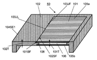
図4と図5は、それぞれ別の態様の従来の複合成形品の断面斜視図である。これらの態様は、良く似ているため、相違がない要素については、図4と図5において、同じ符号が用いられている。 4 and 5 are cross-sectional perspective views of a conventional composite molded article according to another embodiment. Since these aspects are very similar, the same reference numerals are used in FIGS. 4 and 5 for elements that are not different.
図4および5において、複合成形品40、50は、板状部材101と樹脂部材102とからなる。板状部材101と樹脂部材102とは、互いに向かい合う板状部材101の側端面101SFと樹脂部材102の側端面102SFにおいて、互いに接合され、接合面103JFが形成されている。この接合面103JFは、複合成形品40、50の表面において、接合線103JLとして示される。接合線103JLは、直線である。この直線の方向は、通常、複合成形品40、50の一側辺104SE1の方向と平行な方向とされている。これに起因して、接合線103JL上における長さを表現する場合、平行方向長さと云う用語が用いられる場合がある。
4 and 5, the composite molded
板状部材101は、上面側と下面側とに位置する表層基材105a、105bと、これらの表層基材105a、105bの間に位置するコア層基材106とからなる。各表層基材105a、105bは、繊維強化樹脂で形成されている。この繊維強化樹脂は、一方向に多数本配列された連続強化繊維とマトリックス樹脂とからなる。コア層基材106は、各表層基材105a、105bを形成する繊維強化樹脂よりも軟質の軟質材料から形成されている。この軟質材料として、発泡材が用いられている。コア層基材106が軟質材料からなることを利用して、樹脂部材102を形成する樹脂を板状部材101に対し射出成形する過程において、樹脂部材102を形成する樹脂を、コア層基材106を押し縮め、両表層基材105a、105bの間に嵌入させることが可能である。
The plate-
図4の複合成形品40においては、接合面103JFにおいて、樹脂部材102の側端面102SFは、両表層基材105a、105bの間に嵌入されていない。その結果、接合面103JFにおける板状部材101と樹脂部材102との接合強度を補強する目的で、板状部材101を下側から支持する接合突起107が、接合面103JFの部位において、樹脂部材102の側端面102SFに設けられている。このため、複合成形品40においては、樹脂部材102の厚さ102Tが、板状部材101の厚さ101Tより厚くなる。その結果、複合成形品40は、その軽量化において、不利と云える。
In the composite molded
図5の複合成形品50においては、接合面103JFにおいて、樹脂部材102の側端面102SFは、両表層基材105a、105bの間に嵌入されている。この樹脂部材102の嵌入により、嵌入方向にコア層基材106が後退した部位に、樹脂部材102の先端部108が位置している。すなわち、樹脂部材102の先端部108が、両表層基材105a、105bとの間に位置している。その結果、接合面103JFにおける板状部材101と樹脂部材102とのある程度の接合強度が確保される。しかし、複合成形品50において、接合線103JLは、直線をなしているため、樹脂部材101の板状部材102への嵌入は、コア層基材106に対するものに止まり、板状部材101と樹脂部材102との接合強度の更なる向上は、望めない。
In the composite molded
本発明の複合成形品は、図5に示す従来の複合成形品50の問題点を解消することを、一つの目的としている。本発明の複合成形品の一態様を、図1および図2を参照しながら説明する。
One object of the composite molded article of the present invention is to eliminate the problems of the conventional composite molded
図1は、本発明の複合成形品の一態様の断面斜視図である。図2は、図1の複合成形品に用いられている板状部材の断面斜視図である。 FIG. 1 is a cross-sectional perspective view of one embodiment of the composite molded article of the present invention. FIG. 2 is a cross-sectional perspective view of a plate-like member used in the composite molded article of FIG.
図1において、本発明の複合成形品10は、板状部材11と樹脂部材12とからなる。板状部材11と樹脂部材12とは、互いに向かい合う板状部材11の側端面11SFと樹脂部材12の側端面12SFにおいて、互いに凹凸形状を有して接合され、凹凸形状接合面である接合面13JFを形成している。接合面13JFは、複合成形品10の表面において、接合線13JLとして現れる。接合面13JFが凹凸形状であるため、接合線13JLは、凹凸形状を有する曲線である。
In FIG. 1, a composite molded
板状部材11は、上面側に位置する表層基材15aと下面側に位置する表層基材15bと、これらの表層基材15a、15bの間に位置するコア層基材16とからなる。各表層基材15a、15bは、繊維強化樹脂で形成されている。コア層基材16は、各表層基材15a、15bを形成する繊維強化樹脂よりも軟質の軟質材料から形成されている。コア層基材16が軟質材料からなることを利用して、樹脂部材12を形成する樹脂を板状部材11に対し射出成形する過程において、樹脂部材12を形成する樹脂を、コア層基材16を押し縮めて、両表層基材15a、15bの間に嵌入させる。すなわち、板状部材11の両表層基材15a、15bの間に、樹脂部材12の先端部18を位置させる。
The plate-
複合成形品10は、板状部材11と樹脂部材12との間に、前記接合面13JFに加え、接合面13JF2、13JF3および13JF4を有する。ただし、接合面13JF4は、図1が断面図であるため、図1には現れていない。各接合面は、複合成形品10の表面において、前記接合線13JLに加え、接合線13JL2、13JL3および13JL4として現れる。ただし、接合線13JL4は、図1が断面図であるため、図1には現れていない。複合成形品10は、図1において、左側端縁10E、右側端縁10E2、上側端縁10E3および下側端縁10E4を有する。ただし、下側端縁10E4は、図1が断面図であるため、図1には現れていない。
The composite molded
右側端縁10Eの方向と左側端縁10E2との方向は、互いに平行であり、また、上側端縁10E3の方向と下側端縁10E4との方向は、互いに平行である。接合線13JL2の方向は、右側端縁10E2の方向に平行であり、接合線13JL3の方向は、上側端縁10E3の方向に平行であり、接合線13JL4の方向は、下側端縁10E4の方向に平行である。凹凸形状を有する接合線13JLは、凹凸を描きつつ進展し、その進展方向は、左側端縁10Eの方向に平行である。これに起因して、それぞれの接合線上における長さを表現する場合、平行方向長さと云う用語が用いられる場合がある。
The direction of the
複合成形品10において、凹凸形状を有する接合面(凹凸形状接合面)13JFの凹凸形状における凹凸に沿って形成される実際の接合線の長さJL、すなわち、接合線13JLの長さが、各表層基材15a、15bが描く凹凸形状における隣り合う凸部の頂きを結ぶ直線線分の連続からなる凸部通過線13PLの長さ1mm当たり、1.05mm以上とされている。この値は、凹凸の度合いを示す。
In the composite molded
凸部通過線13PLは、通常、直線である。また、凸部通過線13PLが直線の場合、凸部通過線13PLの方向は、通常、左端縁10Eの方向と同じである。すなわち、凸部通過線13PLは、左端縁10Eに平行な直線である。図4に示す複合成形品40、あるいは、図5に示す複合成形品50における接合線103JLは、凹凸形状の曲線ではなく、直線であるため、実際の接合線の長さと接合線103JLの長さとは、一致している。
The convex passage line 13PL is usually a straight line. When the convex passage line 13PL is a straight line, the direction of the convex passage line 13PL is usually the same as the direction of the
複合成形品10は、その接合面13JFが、このような凹凸形状を有するため、接合面が平坦な面である図4あるいは図5に示す複合成形品40あるいは50の場合に比べ、接合面における接合強度が、格段に向上する。複合成形品10において、他の接合面13JF2、13JF3、13JF4についても、必要に応じて、接合面13JFの場合と同様に、接合面の形状を凹凸形状としても良い。
Since the joint surface 13JF has such a concavo-convex shape, the composite molded
軟質材料からなるコア層基材16の側端面の位置が、各表層基材15a、15bの側端面の位置よりも若干内側になるように、コア層基材16の大きさを調整しても良い。このようにすることにより、コア層基材16の軟質の程度、射出圧力の程度、あるいは、樹脂部材12を形成する樹脂の種類に応じて、樹脂部材12の先端部18の大きさを調整することができる。
Even if the size of the core
図3は、図1の複合成形品10における板状部材11を作成するための原基材の分解斜視図である。図3において、原基材11Aは、軟質材料である発泡材からなるコア層基材16A、コア層基材16Aの上面に配置される一方向に多数本引き揃えられた連続強化繊維シート11Aa、コア層基材16Aの下面に配置される一方向に多数本引き揃えられた連続強化繊維シート11Ab、更に、連続強化繊維シート11Aaの上面に配置される一方向に多数本引き揃えられた連続強化繊維シート11Ba、連続強化繊維シート11Abの下面に配置される一方向に多数本引き揃えられた連続強化繊維シート11Bbからなる。
FIG. 3 is an exploded perspective view of the base material for producing the plate-
連続強化繊維シート11Aaにおける連続強化繊維31Aaの配列方向と連続強化繊維シート11Baにおける連続強化繊維31Baの配列方向は、互いに直交する方向とされている。これらの連続強化繊維シートにより、上面側の表層基材15aAが形成される。また、連続強化繊維シート11Abにおける連続強化繊維31Abの配列方向と連続強化繊維シート11Bbにおける連続強化繊維31Bbの配列方向は、互いに直交する方向とされている。これらの連続強化繊維シートにより、下面側の表層基材15bAが形成される。 The arrangement direction of the continuous reinforcement fibers 31Aa in the continuous reinforcement fiber sheet 11Aa and the arrangement direction of the continuous reinforcement fibers 31Ba in the continuous reinforcement fiber sheet 11Ba are orthogonal to each other. The surface layer base material 15aA on the upper surface side is formed by these continuous reinforcing fiber sheets. In addition, the arrangement direction of the continuous reinforcing fibers 31Ab in the continuous reinforcing fiber sheet 11Ab and the arrangement direction of the continuous reinforcing fibers 31Bb in the continuous reinforcing fiber sheet 11Bb are orthogonal to each other. By these continuous reinforcing fiber sheets, the surface layer base material 15bA on the lower surface side is formed.
両表層基材15aA、15bAとコア層基材16Aとを接着する方法には、特に制限はないが、例えば、接着性の不織布やフィルムを、両表層基材15aA、15bAとコア層基材16Aとの間に挟み、プレス成形する方法が好適に用いられる。その他、例えば、両表層基材15aA、15bAとコア層基材16Aとの間に接着剤を塗布する方法がある。
There is no particular limitation on the method for bonding both the surface layer base materials 15aA and 15bA and the core
板状部材の原基材11Aを用いて板状部材11を製造方法には、特に制限はないが、例えば、熱硬化性樹脂を用いたプレス成形法、ハンドレイアップ成形法、スプレーアップ成形法、真空バック成形法、加圧成形法、オートクレーブ成形法、トランスファー成形法を用いることができる。また、例えば、熱可塑性樹脂を用いたプレス成形法、スタンピング成形法を用いることができる。とりわけ、プロセス性、力学特性の観点から、真空バック成形法、プレス成形法、トランスファー成形法が好適に用いられる。
Although there is no restriction | limiting in particular in the manufacturing method of the plate-shaped
板状部材11に樹脂部材12を接合する方法には、特に制限はないが、板状部材11を射出成形機の金型にセットし、型締めを行った後、樹脂部材12を形成する樹脂を射出成形する方法が好適に用いられる。その他、例えば、板状部材11と樹脂部材12と予め別々に作製しておき、これらを接着剤で接合する方法がある。
The method for joining the
複合成形品10において、接合線13JLの長さが、各表層基材15a、15bが描く凹凸形状における隣り合う凸部の頂きを結ぶ直線線分の連続からなる凸部通過線13PLの長さ1mm当たり、1.05mm以上とされている。接合面13JFにおいて、凸部通過線13PLの長さ1mm当たりの接合線13JLの長さが1.05mm以上あれば、接合線13JLの長さが1.05mm未満の場合と比較して、接合面13JFに荷重が掛かった場合に、荷重が分散されるため、格段に接合強度が向上する。
In the composite molded
凸部通過線13PLの長さ1mm当たりの接合線13JLの長さは、好ましくは、1.10mm以上であり、より好ましくは、1.15mm以上である。なお、接合線13JLの長さは、長い方が接合強度は向上する傾向を示すが、必要以上に長くしても、接合強度の向上が頭打ちになるとともに、板状部材あるいは各表層基材の加工が困難となる。これらの点を考慮すると、凸部通過線13PLの長さ1mm当たりの接合線13JLの長さは、5mm以下が好ましく、より好ましくは、4mm以下である。 The length of the joining line 13JL per 1 mm of the length of the protruding portion passing line 13PL is preferably 1.10 mm or more, and more preferably 1.15 mm or more. The length of the joining line 13JL tends to improve the joining strength as long as it is longer than necessary. However, even if the joining line 13JL is longer than necessary, the improvement of the joining strength will reach its peak, and the plate-like member or each surface layer base material Processing becomes difficult. Considering these points, the length of the joining line 13JL per 1 mm of the convex passage line 13PL is preferably 5 mm or less, and more preferably 4 mm or less.
板状部材あるいは各表層基材の側端面11SFが有する凹凸形状の作製法には、特に制限はないが、エンドミル、フライスカッター等を用いてNC加工することで、複雑な凹凸形状であっても作製することが可能である。 There is no particular limitation on the method for producing the concavo-convex shape of the plate-like member or the side end surface 11SF of each surface layer base material, but even if the concavo-convex shape is complicated by NC processing using an end mill, a milling cutter or the like. It is possible to produce.
接合面13JFにおいて各表層基材15a、15bが描く凹凸形状における凸部PAnの数は、凸部通過線13PLの長さ100mm当たり、1乃至100であることが好ましい。この場合、隣り合う凸部の間の凹部Pnの凸部通過線13PLから凹部谷底までの距離を凹部深さLnとすると、凹部深さLnが、0.5乃至100mmであることがより好ましい。
The number of projections PAn in the concavo-convex shape drawn by each surface
凸部PAnの数は、より好ましくは、凸部通過線13PLの長さ100mm当たり、3乃至80である。この場合、凹部深さLnが、1乃至80mmであることがより好ましい。 More preferably, the number of protrusions PAn is 3 to 80 per 100 mm in length of the protrusion passage line 13PL. In this case, the recess depth Ln is more preferably 1 to 80 mm.
凸部PAnの数は、更に好ましくは、凸部通過線13PLの長さ100mm当たり、5乃至60である。この場合、凹部深さLnが、2乃至60mmであることがより好ましい。 More preferably, the number of convex portions PAn is 5 to 60 per 100 mm in length of the convex portion passing line 13PL. In this case, the recess depth Ln is more preferably 2 to 60 mm.
凸部PAnの数が、凸部通過線13PLの長さ100mm当たり、1未満であり、かつ、凹部深さLnが、0.5mm未満であると、接合長さが短く、接合面13JFに荷重が掛かった場合、荷重が分散されないため、接合強度が不充分となることがある。また、凸部PAnの数が、凸部通過線13PLの長さ100mm当たり、100を超え、かつ、凹部深さLnが、100mmを超えると、板状部材11あるいは表層基材15a、15bの加工が困難となったり、加工時間、加工コストが増大したりする。
When the number of the convex portions PAn is less than 1 per 100 mm of the length of the convex portion passage line 13PL and the concave portion depth Ln is less than 0.5 mm, the joining length is short and the load is applied to the joining surface 13JF. When the load is applied, the load is not dispersed, so that the bonding strength may be insufficient. Further, if the number of the convex portions PAn exceeds 100 per 100 mm of the length of the convex portion passage line 13PL and the concave portion depth Ln exceeds 100 mm, the plate-
図6乃至図9は、表層基材の側端面に設けられたそれぞれ異なる凹凸形状を有する凹凸形状接合面の例の平面図である。図6乃至図9において、記号JLは、樹脂部材が接合するときの接合線を示す。記号PAnと記号PAn+1は、隣り合う凸部を示す。記号Pnは、隣り合う凸部PAn、PAn+1の間の凹部を示す。記号PLは、隣り合う凸部PAn、PAn+1の頂きを結ぶ直線線分の連続からなる凸部通過線を示す。記号Lnは、凹部Pnの凸部通過線PLから凹部谷底までの距離、すなわち、凹部深さを示す。記号Fnは、凹部Pnの形状において凸部通過線PLにより形成される凹部開口辺の両端間の距離、すなわち、凹部開口幅を示す。 6 to 9 are plan views of examples of the concavo-convex joint surfaces having different concavo-convex shapes provided on the side end surfaces of the surface layer base material. In FIG. 6 thru | or FIG. 9, the symbol JL shows the joining line when a resin member joins. Symbol PAn and symbol PAn + 1 indicate adjacent convex portions. The symbol Pn indicates a concave portion between adjacent convex portions PAn and PAn + 1. The symbol PL indicates a convex part passage line formed by a continuous line segment connecting adjacent projections PAn and PAn + 1. Symbol Ln indicates the distance from the convex part passage line PL of the concave part Pn to the concave valley bottom, that is, the concave part depth. Symbol Fn indicates the distance between both ends of the concave opening side formed by the convex passage line PL in the shape of the concave Pn, that is, the concave opening width.
凹部深さLnは、凹部開口幅Fnの0.1乃至10倍であることが好ましく、0.5乃至8倍であることがより好ましく、1乃至5倍であることが更に好ましい。凹部深さLnが、凹部開口幅Fnの0.1倍未満であると、特に、接合面に対して、接合面に平行な方向からの荷重が掛かった場合、荷重が分散されにくいため、接合強度が不充分となることがある。なお、凹部深さLnと凹部開口幅Fnとの上記倍率関係は、凸部の全数N(n=1,2,3,・・・N)について、少なくとも90%以上が、上記倍率関係を満足していることを前提とする。 The recess depth Ln is preferably 0.1 to 10 times the recess opening width Fn, more preferably 0.5 to 8 times, and even more preferably 1 to 5 times. If the recess depth Ln is less than 0.1 times the recess opening width Fn, particularly when a load is applied to the joint surface from a direction parallel to the joint surface, the load is difficult to disperse. The strength may be insufficient. It should be noted that the magnification relationship between the recess depth Ln and the recess opening width Fn is such that at least 90% or more of the total number N of projections (n = 1, 2, 3,... N) satisfies the magnification relationship. Assuming that
凹部Pnが、凹部形状の輪郭線の一部に、丸みを有する線分を含んでいることが好ましい。凹部Pnが丸みを有する線分を含んでいることで、実際の接合線JLの長さを長くすることができるほか、シャープな部分が存在する場合に生じやすい応力集中が防止できる。 It is preferable that the concave portion Pn includes a rounded line segment in a part of the concave contour line. Since the concave portion Pn includes a rounded line segment, the length of the actual joint line JL can be increased, and stress concentration that is likely to occur when a sharp portion exists can be prevented.
凹部Pnが、凹部開口幅Fnよりも幅が広い部分を有していても良い。図9の凹部Pnの場合、凹部Pnの右側の接合線JLと左側の接合線JLとは、凹部Pnの谷底方向に向かうに従い、それぞれの間隔が広がっている。すなわち、図9の凹部Pnは、凹部開口幅Fnよりも幅が広い部分を有している。凹部Pnが、凹部開口幅Fnよりも幅が広い部分を有することで、接合面JFに対して、その垂直方向に引張の力が働く場合、アンカー効果を大きくすることができる。 The recess Pn may have a portion wider than the recess opening width Fn. In the case of the recess Pn in FIG. 9, the gap between the bonding line JL on the right side and the bonding line JL on the left side of the depression Pn increases toward the bottom of the recess Pn. That is, the recess Pn in FIG. 9 has a portion wider than the recess opening width Fn. When the recess Pn has a portion wider than the recess opening width Fn, the anchor effect can be increased when a tensile force acts in the direction perpendicular to the joint surface JF.
凹部開口幅Fnよりも幅が広い部分を有している凹部Pnの他の7つの例の平面図が、図10の(a)乃至(g)に示される。図10(a)の凹部Pnの形状は、液滴形である。図10(b)の凹部Pnの形状は、音符形である。図10(c)の凹部Pnの形状は、振り子形である。図10(d)の凹部Pnの形状は、アリ溝形あるいはT字形である。図10(e)の凹部Pnの形状は、鍵形あるいはL字形である。図10(f)の凹部Pnの形状は、尻尾形あるいはJ字形ある。図10(g)の凹部Pnの形状は、菱形あるいは凧形に代表される多角形である。 Plan views of other seven examples of the recess Pn having a portion wider than the recess opening width Fn are shown in FIGS. The shape of the recess Pn in FIG. 10A is a droplet shape. The shape of the recess Pn in FIG. 10B is a note shape. The shape of the recess Pn in FIG. 10C is a pendulum shape. The shape of the recess Pn in FIG. 10D is a dovetail shape or a T-shape. The shape of the recess Pn in FIG. 10E is a key shape or an L shape. The shape of the recess Pn in FIG. 10F is a tail shape or a J shape. The shape of the recess Pn in FIG. 10G is a polygon represented by a rhombus or a bowl.
板状部材11の表層基材15a、15bは、繊維強化樹脂から形成されているが、そこに用いられる樹脂、すなわち、マトリックス樹脂としては、熱可塑性樹脂あるいは熱硬化性樹脂がある。
The
熱可塑性樹脂としては、例えば、ポリエチレン(PE)、ポリプロピレン(PP)、ポリブチレン等のポリオレフィンや、ポリスチレン(PS)、アクリロニトリル−ブタジエン−スチレン共重合体(ABS)、アクリロニトリル−スチレン共重合体(AS)等のスチレン系樹脂や、ポリエチレンテレフタレート(PET)、ポリブチレンテレフタレート(PBT)、ポリトリメチレンテレフタレート(PTT)、ポリエチレンナフタレート(PEN)、液晶ポリエステル等のポリエステルや、ポリオキシメチレン(POM)、ポリアミド(PA)、ポリカーボネート(PC)、ポリメチルメタクリレート(PMMA)、ポリ塩化ビニル(PVC)、ポリフェニレンスルフィド(PPS)、ポリフェニレンエーテル(PPE)、変性PPE、熱可塑性ポリイミド(PI)、ポリアミドイミド(PAI)、ポリエーテルイミド(PEI)、ポリスルホン(PSU)、変性PSU、ポリエーテルスルホン(PES)、ポリケトン(PK)、ポリエーテルケトン(PEK)、ポリエーテルエーテルケトン(PEEK)、ポリエーテルケトンケトン(PEKK)、ポリアリレート(PAR)、ポリエーテルニトリル(PEN)、熱可塑性フェノール系樹脂、フェノキシ樹脂、ポリテトラフルオロエチレン(PTFE)などのフッ素系樹脂、更にポリスチレン系、ポリオレフィン系、ポリウレタン系、ポリエステル系、ポリアミド系、ポリブタジエン系、ポリイソプレン系、フッ素系等の熱可塑エラストマー等や、これらの共重合体、変性体、および2種類以上のブレンド、ポリマーアロイなどがあげられる。 Examples of the thermoplastic resin include polyolefins such as polyethylene (PE), polypropylene (PP), and polybutylene, polystyrene (PS), acrylonitrile-butadiene-styrene copolymer (ABS), and acrylonitrile-styrene copolymer (AS). Styrene resins such as polyethylene terephthalate (PET), polybutylene terephthalate (PBT), polytrimethylene terephthalate (PTT), polyethylene naphthalate (PEN), liquid crystal polyester, and the like, polyoxymethylene (POM), polyamide (PA), polycarbonate (PC), polymethyl methacrylate (PMMA), polyvinyl chloride (PVC), polyphenylene sulfide (PPS), polyphenylene ether (PPE), modified PPE, Plastic polyimide (PI), polyamideimide (PAI), polyetherimide (PEI), polysulfone (PSU), modified PSU, polyethersulfone (PES), polyketone (PK), polyetherketone (PEK), polyetheretherketone (PEEK), polyether ketone ketone (PEKK), polyarylate (PAR), polyether nitrile (PEN), thermoplastic phenol resin, phenoxy resin, polytetrafluoroethylene (PTFE) and other fluorine resins, and polystyrene , Polyolefin-based, polyurethane-based, polyester-based, polyamide-based, polybutadiene-based, polyisoprene-based, fluorine-based thermoplastic elastomers, copolymers, modified products, blends of two or more types, polymer alloys, etc. And the like.
熱硬化性樹脂としては、例えば、不飽和ポリエステル、ビニルエステル、エポキシ、フェノール(レゾール型)、ユリア・メラミン、ポリイミド等や、これらの共重合体、変性体、およびこれらの少なくとも2種のポリマーアロイがあげられる。 Examples of the thermosetting resin include unsaturated polyesters, vinyl esters, epoxies, phenols (resol type), urea melamines, polyimides, copolymers thereof, modified products, and at least two polymer alloys thereof. Can be given.
マトリックス樹脂は、剛性、強度に優れる熱硬化性樹脂が好ましく、エポキシ樹脂を主成分とする熱硬化性樹脂が、成形品の力学特性の観点から、より好ましい。熱硬化性樹脂には、更なる耐衝撃性向上のために、熱可塑性樹脂および/またはその他のエラストマー、もしくは、ゴム成分が添加されていても良い。 The matrix resin is preferably a thermosetting resin excellent in rigidity and strength, and a thermosetting resin mainly composed of an epoxy resin is more preferable from the viewpoint of the mechanical properties of the molded product. A thermoplastic resin and / or other elastomer or rubber component may be added to the thermosetting resin to further improve impact resistance.
強化繊維としては、例えば、アルミニウム繊維、黄銅繊維、ステンレス繊維などの金属繊維、ポリアクリロニトリル系、レーヨン系、リグニン系、ピッチ系等の炭素繊維や黒鉛繊維、ガラス繊維、シリコンカーバイト繊維、シリコンナイトライド繊維などの無機繊維や、アラミド繊維、ポリパラフェニレンベンゾビスオキサゾール(PBO)繊維、ポリフェニレンスルフィド繊維、ポリエステル繊維、アクリル繊維、ナイロン繊維、ポリエチレン繊維などの有機繊維等が使用できる。これらの強化繊維は単独で用いても、また、2種以上併用しても良い。 Examples of reinforcing fibers include metal fibers such as aluminum fibers, brass fibers, and stainless fibers, carbon fibers such as polyacrylonitrile, rayon, lignin, and pitch, graphite fibers, glass fibers, silicon carbide fibers, and siliconite. Inorganic fibers such as ride fibers, organic fibers such as aramid fibers, polyparaphenylene benzobisoxazole (PBO) fibers, polyphenylene sulfide fibers, polyester fibers, acrylic fibers, nylon fibers, and polyethylene fibers can be used. These reinforcing fibers may be used alone or in combination of two or more.
強化繊維は、比強度、比剛性、軽量性のバランスの観点から、炭素繊維がより好ましく、比強度、比弾性率に優れる点で、少なくともポリアクリロニトリル系炭素繊維を含むことが好ましい。 The reinforcing fiber is more preferably a carbon fiber from the viewpoint of the balance of specific strength, specific rigidity, and lightness, and preferably contains at least polyacrylonitrile-based carbon fiber in view of excellent specific strength and specific elastic modulus.
各表層基材15a、15bの強化繊維は、強化繊維を含む複数の層から構成される強化繊維シートであっても良い。強化繊維は、連続強化繊維であることが、より高強度、高剛性が得られることから、好ましい。連続強化繊維を含む強化繊維シートにおける連続強化繊維の長さは、10mm以上であれば良い。しかし、必ずしも強化繊維シートの全体にわたって連続している必要はなく、途中で分断されていても良い。連続強化繊維の形態としては、クロス、一方向引き揃えシート、ブレイドが例示できる。プロセス面の観点から、クロス、一方向引き揃えシートが好適に使用される。これらの形態は、単独で使用しても、2種以上の形態を併用しても良い。中でも、マルチフィラメントが一方向に引き揃えられたシートが、より効率良く強度、剛性を得られることから、好ましい。
The reinforcing fiber of each surface
表層基材として、強化繊維を含んだシートを用いる場合、強化繊維の割合は、成形性、力学特性の観点から、20乃至90体積%が好ましく、30乃至80体積%がより好ましい。なお、体積%の測定は、マトリックスが樹脂の場合は、JIS K7075−1991(炭素繊維強化プラスチックの繊維含有率及び空洞率試験方法)に記載されている方法で測定する。 When a sheet containing reinforcing fibers is used as the surface layer base material, the proportion of reinforcing fibers is preferably 20 to 90% by volume and more preferably 30 to 80% by volume from the viewpoints of moldability and mechanical properties. The volume% is measured by the method described in JIS K7075-1991 (Fiber content rate and void ratio test method of carbon fiber reinforced plastic) when the matrix is a resin.
樹脂部材12に使用される樹脂としては、特に制限はないが、射出成形などを用いた接合形状作製の観点からは、熱可塑性樹脂が好ましく用いられる。
Although there is no restriction | limiting in particular as resin used for the
樹脂部材の形成に用いられる熱可塑性樹脂としては、板状部材の形成に用いられる上述の熱可塑性樹脂を用いることができる。それらの中で、とりわけ、耐熱性、耐薬品性の観点からは、ポリフェニレンスルフィド(PPS)が、成形品外観、寸法安定性の観点からは、ポリカーボネート(PC)、ポリフェニレンエーテル(PPE)、スチレン系樹脂が、成形品の強度、耐衝撃性の観点からは、ポリアミド(PA)がより好ましく用いられる。 As the thermoplastic resin used for forming the resin member, the above-described thermoplastic resin used for forming the plate-like member can be used. Among them, polyphenylene sulfide (PPS) is particularly preferable from the viewpoints of heat resistance and chemical resistance, and polycarbonate (PC), polyphenylene ether (PPE), and styrene are preferable from the viewpoint of appearance of the molded product and dimensional stability. From the viewpoint of the strength and impact resistance of the molded product, polyamide (PA) is more preferably used as the resin.
複合成形品の高強度、高剛性化を図るために、樹脂部材12の樹脂として、強化繊維が含有した樹脂を用いることも好ましい。強化繊維としては、上述の強化繊維が例示される。樹脂部材12が電波透過性を必要とする場合には、強化繊維として、非導電性のガラス繊維を用いることも好ましい。
In order to increase the strength and rigidity of the composite molded product, it is also preferable to use a resin containing reinforcing fibers as the resin of the
板状部材11におけるコア層基材16を形成する軟質材料としては、例えば、発泡材、ハニカム材等の有孔材、繊維シート、樹脂シートがある。発泡材および/またはハニカム材を使用すると、より軽量な板状部材11が得られる。
Examples of the soft material forming the core
軟質材料の材質としては、特に制限はないが、軟質材料が熱可塑性樹脂である場合は、板状部材の形成に用いられる上述の熱可塑性樹脂を用いることができる。それらの中で、とりわけ、軽量化の観点からは、ポリプロピレン(PP)、ポリエチレン(PE)などのポリオレフィン系樹脂が、各表層基材15a、15bおよび樹脂部材12との接着性の観点からは、ポリアミド系樹脂、ポリエステル系樹脂、ポリビニルアルコール系樹脂、変性ポリオレフィン、それらの共重合体、およびそれらのポリマーアロイなどが好ましく用いられる。
The material of the soft material is not particularly limited, but when the soft material is a thermoplastic resin, the above-described thermoplastic resin used for forming the plate-like member can be used. Among them, in particular, from the viewpoint of weight reduction, polyolefin resins such as polypropylene (PP) and polyethylene (PE) are used from the viewpoint of adhesiveness to the surface
コア層基材16にある程度の剛性を持たせたい場合には、軟質材料は、ガラス繊維や炭素繊維等の強化繊維を含んでいても良い。
When the core
各表層基材15a、15bとコア層基材16との接着方法としては、特に制限はなく、表層基材とコア層基材との間に、接着性の不織布、フィルム等を配置させて接着させても良く、あるいは、一方あるいは双方の基材に接着剤を塗布して接着させても良い。
The method for adhering the surface
本発明の複合成形品の用途としては、例えば、パーソナルコンピューター、ディスプレイ、OA機器、携帯電話、携帯情報端末、ファクシミリ、コンパクトディスクプレーヤー、ポータブルMDプレーヤー、携帯用ラジオカセット、PDA(電子手帳などの携帯情報端末)、デジタルビデオカメラ、デジタルスチルカメラ、光学機器、オーディオ、エアコン、照明機器、娯楽用品、玩具用品、その他家電製品などの電気・電子機器の筐体の構成材料がある。また、トレイ、シャーシ、あるいは、ケースの構成材料がある。更に、種々の機構部品の構成材料がある。また、更に、自動車や航空機の電装部材や内装部品の構成材料がある。 Applications of the composite molded article of the present invention include, for example, personal computers, displays, OA equipment, mobile phones, personal digital assistants, facsimile machines, compact disc players, portable MD players, portable radio cassettes, PDAs (portable electronic notebooks, etc.) Information terminals), digital video cameras, digital still cameras, optical equipment, audio equipment, air conditioners, lighting equipment, entertainment goods, toy goods, and other electrical and electronic equipment casing materials. There are also materials for the tray, chassis, or case. Furthermore, there are various constituent materials for mechanical parts. Furthermore, there are constituent materials for electrical components and interior parts of automobiles and aircraft.
とりわけ、本発明の複合成形品は、その優れた軽量性、高強度、高剛性、薄肉性を活かして、電気・電子機器用筐体の構成材料として好適に用いられる。更には、薄肉で広幅のディスプレイを必要とするノート型パーソナルコンピューターや携帯情報端末などの筐体の構成材料として好適に用いられる。 In particular, the composite molded article of the present invention is suitably used as a constituent material of a housing for electric / electronic devices, taking advantage of its excellent lightness, high strength, high rigidity and thinness. Furthermore, it is suitably used as a constituent material of a casing of a notebook personal computer or a portable information terminal that requires a thin and wide display.
本発明の複合成形品は、その用途によっては、難燃性を有していることが好ましい。板状部材11および樹脂部材12のUL−94規格に基づく垂直燃焼試験における難燃性が、0.1乃至3.0mmのいずれかの厚みの試験片で、V−1またはV−0であることが好ましい。0.1乃至1.0mmのいずれかの厚みの試験片で、V−1またはV−0であることがより好ましい。
The composite molded article of the present invention preferably has flame retardancy depending on the application. The flame retardancy in the vertical combustion test based on the UL-94 standard of the
板状部材11および樹脂部材12のいずれかもしくは双方が、難燃剤を含むことが好ましい。難燃剤としては、例えば、ハロゲン化合物、アンチモン化合物、リン化合物、窒素化合物、シリコーン化合物、フッ素化合物、フェノール化合物、あるいは、金属水酸化物がある。中でも、環境負荷を抑えるという観点から、リン系の難燃剤が好ましい。リン系の難燃剤としては、例えば、リン酸エステル、縮合リン酸エステル、ホスファフェナントレン系化合物などのリン含有化合物や赤リンがある。中でも、赤リンは、難燃剤を付与する働きをするリン原子含有率が大きいため、十分な難燃効果を得るために、加えるべき難燃剤の添加量が少量で済む。
Either or both of the plate-
更に、板状部材11および樹脂部材12に用いられる樹脂には、要求される特性に応じ、本発明の目的を損なわない範囲で、他の充填材や添加剤が含有されていても良い。充填材や添加剤としては、例えば、無機充填材、導電性付与剤、結晶核剤、紫外線吸収剤、酸化防止剤、制振剤、抗菌剤、防虫剤、防臭剤、着色防止剤、熱安定剤、離型剤、帯電防止剤、親水性付与剤、可塑剤、滑剤、着色剤、顔料、染料、発泡剤、制泡剤、カップリング剤がある。
Furthermore, the resin used for the plate-
以下に、本発明の具体的実施例を説明する。 Hereinafter, specific examples of the present invention will be described.
実施例における特性評価方法:
(1)引張クラック発生荷重
下記、試験装置、試験片、試験条件で試験を行った。
・試験装置名:精密万能試験機 (島津製作所製:オートグラフ)
・試験片:板状部材11と樹脂部材12の接合部から幅40mm×長さ50mmの試験片を切り出した。
・チャック間距離:30mm
・クロスヘッドスピード:1.6mm/min。Characteristic evaluation method in Examples:
(1) Tensile crack generation load The test was performed with the following test equipment, test piece, and test conditions.
・ Test equipment name: Precision universal testing machine (manufactured by Shimadzu Corporation: Autograph)
Test piece: A test piece having a width of 40 mm and a length of 50 mm was cut out from the joint between the plate-
・ Distance between chucks: 30mm
-Crosshead speed: 1.6 mm / min.
(2)接合部反り
樹脂部材12における立ち壁19(図1参照)から板状部材11との接合部に対して、直角にL型のステンレス製の定規を立てて当て、該ステンレス製定規と接合部の表面との間に隙間ゲージを挿入して、間隙の有無およびその大きさ、すなわち、接合部の反りを測定し、各サンプルの最も反りの大きい箇所の数値を、接合部反りとした。(2) Warpage of joint portion An L-shaped stainless steel ruler is placed at a right angle from the standing wall 19 (see FIG. 1) of the
(3)凸部通過線1mm当たりの実際の接合線の長さ
射出成形により成形された複合成形品10の凹凸形状接合面における凹凸の繰り返し単位の長さを、定規による測定および計算によって求めた。凹凸形状の輪郭線の一部に丸みを有する線分が存在する場合は、その丸みの半径または直径を測定し、その値から円周を求める公式により、実際の接合線の長さを計算した。各凹凸の繰り返し単位における接合線の長さの合計を、直線からなる凸部通過線の長さ、すなわち、平行方向長さで割って、凸部通過線の長さ、すなわち、平行方向長さ1mm当たりの実際の接合線の長さとした。(3) Length of actual joining line per 1 mm of convex part passing line The length of the repeating unit of the unevenness on the uneven surface of the composite molded
(4)凸部通過線の長さ100mm当たりの凸部の数
射出成形により成形された複合成形品10の凹凸形状接合面における凹凸の繰り返し単位の長さを、定規による測定および計算によって求めた。凹凸形状の輪郭線の一部に丸みを有する線分が存在する場合は、その丸みの半径または直径を測定し、その値から円周を求める公式により、実際の接合線の長さを計算した。凹凸の繰り返し単位毎に、凸部が1個存在するため、その繰り返し単位当たりの凸部通過線の長さを定規で測定し、100mmを、繰り返し単位当たりの凸部通過線の長さで割って、凸部通過線の長さ100mm当たりの凸部の数とした。(4) Number of convex portions per 100 mm length of convex portion passing line The length of the repeating unit of the concave and convex portions on the concave and convex shape joint surface of the composite molded
(5)凹部深さLn
射出成形により成形された複合成形品10の凹部の深さを定規で測定した。(5) Concave depth Ln
The depth of the concave portion of the composite molded
(6)凹部開口幅Fn
射出成形により成形された複合成形品10の凹部の開口幅を定規で測定した。(6) Concave opening width Fn
The opening width of the concave portion of the composite molded
(7)Ln/Fnの値
上記(5)と(6)の測定値から計算により求めた。(7) Value of Ln / Fn It calculated | required by calculation from the measured value of said (5) and (6).
板状部材11の表層基材用として、炭素繊維一方向プリプレグシート(UD PP)P3052S−12(東レ(株)製、炭素繊維T700S(強度4900MPa、弾性率230GPa、炭素繊維重量含有率67重量%、ベースレジン:エポキシ樹脂)を、繊維配列方向が直交するように、2層積層した積層体を2枚作製し、その内の1枚の積層体は、上面側の表層基材15aとし、他の1枚の積層体は、下面側の表層基材15bとした。コア層基材16として、発泡材(古河電気工業(株)製エフセル(同社の登録商標)の製品番号RC2010)(2倍発泡ポリプロピレン)を準備した。
Carbon fiber unidirectional prepreg sheet (UD PP) P3052S-12 (manufactured by Toray Industries, Inc., carbon fiber T700S (strength: 4900 MPa, elastic modulus: 230 GPa, carbon fiber weight content: 67% by weight) , Base resin: epoxy resin) so that two layers are laminated so that the fiber arrangement direction is orthogonal to each other, and one of the laminates is used as a surface
準備したコア層基材16の上下面に、接着性ポリオレフィン不織布(日本バイリーン(株)製、融点150℃、目付15g/m2)を配し、更に、その上下面に、作製した表層基材15a、15bを配し、その後、これらをプレス成形(金型温度160℃、圧力6MPa、予熱時間5分、硬化時間30分)し、板状体を得た。得られた板状体を、300mm×230mmのサイズに加工後、NC加工により、表1の実施例1および図6に示す凹凸形状接合面を、得られた板状体の一側端部に形成し、板状部材11を作製した。Adhesive polyolefin nonwoven fabric (manufactured by Nippon Vilene Co., Ltd., melting point 150 ° C., basis weight 15 g / m 2 ) is arranged on the upper and lower surfaces of the prepared core
板状部材11を射出成形金型内にセットし、型締めを行った後、樹脂部材12を形成する樹脂である共重合ポリアミド繊維強化樹脂CM3511−G60(東レ(株)製、ガラス繊維含有量60重量%)を射出成形して、図1に示す、立ち壁19を有する樹脂部材12の立ち壁19とは反対側の一側端が、板状部材11の凹凸形状に侵入し、凹凸形状接合面13JFを有して、板状部材11に接合された複合成形品10を製造した。複合成形品10において、立ち壁19から凹凸形状接合面13JFまでの樹脂部材12の厚みは、1.5mmとし、樹脂部材12の左側縁10Eに沿う幅は、30mmとした。
After the plate-
実施例1における板状体に、NC加工により、表1の実施例2および図7に示す凹凸形状接合面を形成した以外は、実施例1と同様の方法で複合成形品を作製した。 A composite molded article was produced in the same manner as in Example 1 except that the uneven surface of Example 2 in Table 1 and FIG. 7 was formed on the plate-like body in Example 1 by NC processing.
実施例1における板状体に、NC加工により、表1の実施例3および図7に示す凹凸形状接合面を形成した以外は、実施例1と同様の方法で複合成形品を作製した。 A composite molded article was produced in the same manner as in Example 1 except that the uneven surface having the uneven shape shown in Example 3 in Table 1 and FIG. 7 was formed on the plate-like body in Example 1 by NC processing.
実施例1における板状体に、NC加工により、表2の実施例4および図8に示す凹凸形状接合面を形成した以外は、実施例1と同様の方法で複合成形品を作製した。 A composite molded product was produced in the same manner as in Example 1 except that the uneven surface of the plate-like body in Example 1 shown in Example 4 of Table 2 and FIG. 8 was formed by NC processing.
実施例1における板状体に、NC加工により、表2の実施例5および図9に示す凹凸形状接合面を形成した以外は、実施例1と同様の方法で複合成形品を作製した。 A composite molded article was produced in the same manner as in Example 1 except that the uneven surface having the uneven shape shown in Example 5 in Table 2 and FIG. 9 was formed on the plate-like body in Example 1 by NC processing.
実施例1における板状体に、NC加工により、表3の比較例1に示す直線からなる接合面を形成した以外は、実施例1と同様の方法で、図5に示す複合成形品50を作製した。
The composite molded
板状部材101(図4参照)の表層基材用として、炭素繊維一方向プリプレグシート(UD PP)P3052S−12(東レ(株)製、炭素繊維T700S(強度4900MPa、弾性率230GPa、炭素繊維重量含有率67重量%、ベースレジン:エポキシ樹脂)を、繊維配列方向が直交するように、2層積層した積層体を2枚作製し、その内の1枚の積層体は、上面側の表層基材105aとし、他の1枚の積層体は、下面側の表層基材105bとした。コア層基材106として、発泡材(古河電気工業(株)製エフセル(同社の登録商標)の製品番号RC2010)(2倍発泡ポリプロピレン)を準備した。
Carbon fiber unidirectional prepreg sheet (UD PP) P3052S-12 (manufactured by Toray Industries, Inc., carbon fiber T700S (strength 4900 MPa, elastic modulus 230 GPa, carbon fiber weight) for the surface layer substrate of the plate-like member 101 (see FIG. 4) Two laminates were prepared by laminating two layers of a 67% by weight content of base resin (epoxy resin) so that the fiber arrangement direction was orthogonal, and one of the laminates was a surface layer base on the upper surface side. The
準備したコア層基材106の上下面に、接着性ポリオレフィン不織布(日本バイリーン(株)製、融点150℃、目付15g/m2)を配し、更に、その上下面に、作製した表層基材105a、105bを配し、板状部材101となる板状基材を用意した。Adhesive polyolefin non-woven fabric (manufactured by Nippon Vilene Co., Ltd., melting point 150 ° C., basis weight 15 g / m 2 ) is arranged on the upper and lower surfaces of the prepared core
更に、別途、樹脂部材102となる樹脂成形体を用意した。この樹脂成形体は、板状部材101の端部が載置されるためのオーバーラップ部(接合突起107)(幅3mm、厚さ1mm)を有する。
Furthermore, a resin molded body to be the
オーバーラップ部の上下面に、接着性共重合ナイロン不織布(日本バイリーン(株)製、融点150℃、目付40g/m2)を配し、板状基材と樹脂成形体とをプレス成形(金型温度160℃、圧力6MPa、予熱時間5分、硬化時間30分)して、複合成形体を製造した。複合成形体を、300mm×230mmのサイズに加工後、NC加工により、表3の比較例2に示す直線からなるの接合面を形成した以外は、実施例1と同様の方法で、図4に示す複合成形品40を作製した。Adhesive copolymer nylon nonwoven fabric (manufactured by Nippon Vilene Co., Ltd., melting point 150 ° C., basis weight 40 g / m 2 ) is disposed on the upper and lower surfaces of the overlap portion, and the plate-like substrate and the resin molded body are press-molded (gold) The mold temperature was 160 ° C., the pressure was 6 MPa, the preheating time was 5 minutes, and the curing time was 30 minutes. The composite molded body was processed into a size of 300 mm × 230 mm, and then NC processing was performed in the same manner as in Example 1 except that a joining surface consisting of a straight line shown in Comparative Example 2 in Table 3 was formed. The composite molded
実施例1乃至5の複合成形品について、引張クラック発生荷重を測定したところ、十分な接合強度が得られていることが確認された。これらの複合成形品は、板状部材と樹脂部材とが上下に重なり合う状態での接合部を有しないため、その分、薄肉化が図られていた。一方、比較例1の複合成形品においては、充分な引張クラック発生荷重が得られず、接合部反りも大きかった。比較例2の複合成形品においては、引張クラック発生荷重は充分であったが、オーバーラップ部の存在により、薄肉化が達成できなかった。 When the tensile crack generation load was measured for the composite molded articles of Examples 1 to 5, it was confirmed that sufficient bonding strength was obtained. Since these composite molded products do not have a joint portion in a state where the plate-like member and the resin member overlap each other, the thickness is reduced accordingly. On the other hand, in the composite molded product of Comparative Example 1, a sufficient tensile crack generation load could not be obtained, and the joint warp was large. In the composite molded product of Comparative Example 2, the tensile cracking load was sufficient, but the thinning could not be achieved due to the presence of the overlap portion.
表1乃至3中の各項目の説明:
項目1:繊維の種類、
項目2:ベースレジン
項目3:発泡材の材質
項目4:繊維の種類
項目5:ベースレジン
項目6:凹部Pnの形状
項目7:凹部Pnの凹部形状の輪郭線における丸みを有する線分の有無
項目8:凸部通過線PLの長さ1mm当たりの実際の接合線の長さ(単位:mm)
項目9:凸部通過線PLの長さ100mm当たりの凸部の数
項目10:凹部深さLn(単位:mm)
項目11:凹部開口幅Fn(単位:mm)
項目12:Ln/Fnの値
項目13:板状部材と樹脂部材との上下方向におけるオーバーラップ部の有無
項目14:引張クラック発生荷重(単位:N)
項目15:接合部反りの値(単位:mm)Explanation of each item in Tables 1 to 3:
Item 1: fiber type,
Item 2: Base resin Item 3: Material of foam material Item 4: Fiber type Item 5: Base resin Item 6: Shape of recess Pn Item 7: Presence / absence of a round line in the contour line of the recess shape of recess Pn 8: Actual length of the joining line per 1 mm of the convex part passing line PL (unit: mm)
Item 9: Number of convex portions per 100 mm length of convex portion passing line PL Item 10: Depth of concave portion Ln (unit: mm)
Item 11: recess opening width Fn (unit: mm)
Item 12: Ln / Fn value Item 13: Presence / absence of overlap portion in the vertical direction between the plate member and the resin member Item 14: Tensile crack generation load (unit: N)
Item 15: Joint warpage value (unit: mm)

本発明の複合成形品は、ノート型パーソナルコンピューターや携帯端末などの電気・電子機器筐体の構成部材として好適に用いることができるのみならず、その軽量性、高強度、高剛性、薄肉性を活かして、自動車部品の構成部材としても好適に用いることができる。 The composite molded product of the present invention can be suitably used as a constituent member of an electric / electronic device casing such as a notebook personal computer or a portable terminal, but also has lightness, high strength, high rigidity, and thinness. Taking advantage of it, it can also be suitably used as a component of automobile parts.
Claims (16)
(b)用意された板状部材を、射出成形機の金型に収容する工程、および、
(c)前記板状部材が前記金型に収容された前記射出成形機において、少なくとも前記板状部材の凹凸形状を有する前記端面に対し、樹脂を射出し、該樹脂を前記板状部材の凹凸形状を有する前記端面に接合させるとともに、該樹脂が、前記両表層基材の間に嵌入するように射出成形する工程、
とからなる請求項1に記載の複合成形品の製造方法。(A) A surface layer base material formed on the upper surface side and the lower surface side formed of a fiber reinforced resin, and a core layer base formed between a material softer than the fiber reinforced resin, located between the surface layer base materials. A step of preparing a plate-like member in which an uneven shape is formed on the end face by providing a plurality of rows of grooves extending inward from the end face at one end face of the plate-like body made of a material;
(B) a step of accommodating the prepared plate-like member in a mold of an injection molding machine, and
(C) In the injection molding machine in which the plate member is accommodated in the mold, at least the end surface having the uneven shape of the plate member is injected with resin, and the resin is uneven on the plate member. A step of performing injection molding so that the resin is fitted between the two surface layer base materials while being bonded to the end surface having a shape;
The manufacturing method of the composite molded product of Claim 1 which consists of these.
Priority Applications (1)
| Application Number | Priority Date | Filing Date | Title |
|---|---|---|---|
| JP2008544681A JP4858544B2 (en) | 2007-09-11 | 2008-09-04 | Composite molded article and manufacturing method thereof |
Applications Claiming Priority (4)
| Application Number | Priority Date | Filing Date | Title |
|---|---|---|---|
| JP2007235036 | 2007-09-11 | ||
| JP2007235036 | 2007-09-11 | ||
| JP2008544681A JP4858544B2 (en) | 2007-09-11 | 2008-09-04 | Composite molded article and manufacturing method thereof |
| PCT/JP2008/065939 WO2009034906A1 (en) | 2007-09-11 | 2008-09-04 | Composite shaped article and process for manufacturing the same |
Publications (2)
| Publication Number | Publication Date |
|---|---|
| JPWO2009034906A1 JPWO2009034906A1 (en) | 2010-12-24 |
| JP4858544B2 true JP4858544B2 (en) | 2012-01-18 |
Family
ID=40451915
Family Applications (1)
| Application Number | Title | Priority Date | Filing Date |
|---|---|---|---|
| JP2008544681A Active JP4858544B2 (en) | 2007-09-11 | 2008-09-04 | Composite molded article and manufacturing method thereof |
Country Status (8)
| Country | Link |
|---|---|
| US (1) | US8173238B2 (en) |
| EP (1) | EP2199064B1 (en) |
| JP (1) | JP4858544B2 (en) |
| KR (1) | KR101196787B1 (en) |
| CN (1) | CN101835596B (en) |
| ES (1) | ES2397240T3 (en) |
| TW (1) | TWI378027B (en) |
| WO (1) | WO2009034906A1 (en) |
Families Citing this family (41)
| Publication number | Priority date | Publication date | Assignee | Title |
|---|---|---|---|---|
| JP5584398B2 (en) * | 2008-05-14 | 2014-09-03 | 三菱電機株式会社 | PANEL PANEL, MANUFACTURING METHOD THEREOF, AND ELECTRONIC DEVICE PROVIDED WITH THE BOX |
| JP5458529B2 (en) * | 2008-08-22 | 2014-04-02 | 東レ株式会社 | Joining method and integral molded product |
| JP5648270B2 (en) * | 2009-04-24 | 2015-01-07 | 三菱レイヨン株式会社 | Fiber-reinforced composite material molded article and its manufacturing method |
| JP5344032B2 (en) | 2010-01-13 | 2013-11-20 | 東レ株式会社 | Injection molded product and manufacturing method thereof |
| JP2011166124A (en) * | 2010-01-14 | 2011-08-25 | Toray Ind Inc | Electrical and electronic equipment housing |
| TWI383883B (en) * | 2010-11-04 | 2013-02-01 | Advanced Int Multitech Co Ltd | Manufacturing Method of Composite Workpiece with Embedded Magnetic Element |
| WO2013142774A1 (en) * | 2012-03-23 | 2013-09-26 | Cutting Dynamics, Inc. | Moulded fibre reinforced composite blank with guide hole |
| US9393745B2 (en) * | 2012-05-15 | 2016-07-19 | Hexcel Corporation | Over-molding of load-bearing composite structures |
| CN104470715B (en) | 2012-07-18 | 2017-02-22 | 三菱丽阳株式会社 | Fiber reinforced composite material structure and composite material molding using same as well as manufacturing method therefor |
| US9801294B2 (en) * | 2012-11-29 | 2017-10-24 | Sunteng New Technology Co., Ltd. | Electronic device casing including coupling structure and method of manufacturing same |
| FR2998826B1 (en) * | 2012-12-03 | 2015-05-29 | Peugeot Citroen Automobiles Sa | INSERT WITH A DENTAL CONTAINER DISSIPATOR FOR BI-MATERIAL LINK |
| JP5972854B2 (en) * | 2013-12-17 | 2016-08-17 | 三菱重工業株式会社 | Joining method and joined body of fiber reinforced composite member, and manufacturing method of wind turbine blade |
| TWI562895B (en) * | 2014-06-11 | 2016-12-21 | Compal Electronics Inc | Composite plate structure and manufacturing method thereof |
| CN105504788B (en) * | 2014-09-30 | 2016-09-07 | 比亚迪股份有限公司 | Injection-molded article of a kind of variety classes resin and preparation method thereof and the injection-molded article prepared by the method and application thereof |
| US10500814B2 (en) | 2014-12-08 | 2019-12-10 | Dell Products L.P. | Thermoplastic composite materials for portable information handling system enclosures |
| CN105372823B (en) * | 2015-12-08 | 2017-10-27 | 上海天马微电子有限公司 | Stereoscopic display device |
| JP2017136740A (en) * | 2016-02-03 | 2017-08-10 | レノボ・シンガポール・プライベート・リミテッド | Laminate, member for housing, electronic equipment and method for manufacturing member for housing |
| CN108602299B (en) * | 2016-04-05 | 2020-06-26 | 惠普发展公司,有限责任合伙企业 | Multilayer structure for electronic device housing |
| WO2017191668A1 (en) * | 2016-05-02 | 2017-11-09 | 日産自動車株式会社 | Fiber-reinforced resin molded article and method for manufacturing same |
| US10668674B2 (en) * | 2016-05-18 | 2020-06-02 | Dell Products L.P. | Apparatus and method for a high performance carbon fiber laminate enclosure part for an information handling system |
| KR101806707B1 (en) * | 2016-06-09 | 2017-12-07 | 현대자동차주식회사 | Knee bolster of gloove box for vehicle |
| BE1024734B1 (en) | 2016-11-10 | 2018-06-19 | Ivc Bvba | FLOOR PANEL AND METHOD FOR MANUFACTURING A FLOOR PANEL |
| CN106696312A (en) * | 2017-01-25 | 2017-05-24 | 合肥联宝信息技术有限公司 | Embedded forming technology for composite board, composite board and forming milling cutter |
| JP6823519B2 (en) * | 2017-03-24 | 2021-02-03 | 日鉄ケミカル&マテリアル株式会社 | Fiber reinforced composite molded article and its manufacturing method |
| JP6859822B2 (en) * | 2017-04-14 | 2021-04-14 | トヨタ紡織株式会社 | Resin molded product and its manufacturing method |
| CN109270992A (en) * | 2017-07-17 | 2019-01-25 | 仁宝电脑工业股份有限公司 | Tabular component, shell comprising tabular component and preparation method thereof |
| JP6491720B1 (en) * | 2017-09-26 | 2019-03-27 | レノボ・シンガポール・プライベート・リミテッド | Method of manufacturing case member, laminate, case member and electronic device |
| WO2020014936A1 (en) * | 2018-07-20 | 2020-01-23 | 五行科技股份有限公司 | Sheet-shaped member, composite molded member and fabrication method for composite molded member |
| EP3650191A1 (en) | 2018-11-06 | 2020-05-13 | Covestro Deutschland AG | Molded composite article, method for the production thereof and use thereof |
| US20210331440A1 (en) | 2018-09-06 | 2021-10-28 | Covestro Intellectual Property Gmbh & Co. Kg | Molded composite article, method for the production thereof and use thereof |
| CN109551833A (en) * | 2018-11-23 | 2019-04-02 | 合肥联宝信息技术有限公司 | A kind of structure and machining method of composite material |
| CN109677028A (en) * | 2018-12-29 | 2019-04-26 | 上海超惠通风环保设备有限公司 | A kind of high-strength light advanced composite structure |
| JP7226127B2 (en) * | 2019-06-20 | 2023-02-21 | トヨタ紡織株式会社 | Method for manufacturing vehicle interior material |
| JP2022539227A (en) * | 2019-07-01 | 2022-09-07 | ビーエーエスエフ ソシエタス・ヨーロピア | Overmolding of profiles for producing moldings, moldings obtained therefrom and uses thereof |
| CN112824099A (en) * | 2019-11-20 | 2021-05-21 | 虞霞 | Composite plate, shell with composite plate and manufacturing method of composite plate |
| CN111267452B (en) * | 2020-01-21 | 2021-02-09 | 江苏奇一科技有限公司 | Continuous honeycomb core material, honeycomb core sandwich composite plate and preparation method and equipment thereof |
| CN113799316A (en) * | 2020-06-17 | 2021-12-17 | 五行科技股份有限公司 | Method for manufacturing composite board |
| CN113811104A (en) * | 2020-06-17 | 2021-12-17 | 五行科技股份有限公司 | Composite board and manufacturing method thereof |
| CN112389041A (en) * | 2020-11-27 | 2021-02-23 | 中科威禾科技(肇庆)有限公司 | Composite of resin laminated plate and metal plate and manufacturing method thereof |
| JP7526084B2 (en) | 2020-12-04 | 2024-07-31 | ニッタ株式会社 | Wipers |
| EP4431381A1 (en) | 2023-03-16 | 2024-09-18 | AIRBUS HELICOPTERS DEUTSCHLAND GmbH | A structurally bonded arrangement |
Citations (5)
| Publication number | Priority date | Publication date | Assignee | Title |
|---|---|---|---|---|
| JPS4815017Y1 (en) * | 1970-04-14 | 1973-04-25 | ||
| JPS62159619A (en) * | 1986-01-09 | 1987-07-15 | 松下電器産業株式会社 | Electric rice cooker |
| JPH04305436A (en) * | 1991-04-03 | 1992-10-28 | Nitta Ind Corp | Mold for mutually welding and parts of thermoplastic resin strips |
| JP2006044259A (en) * | 2004-07-07 | 2006-02-16 | Toray Ind Inc | Integrated molded product and its manufacturing method |
| JP2007038519A (en) * | 2005-08-03 | 2007-02-15 | Toray Ind Inc | Composite molded component |
Family Cites Families (9)
| Publication number | Priority date | Publication date | Assignee | Title |
|---|---|---|---|---|
| DE2111257B2 (en) * | 1971-03-09 | 1974-02-07 | Fleuchaus, Leo, Dipl.-Ing., 8000 Muenchen | Tongue and groove connection between the deck and the hull shell of a plastic hull |
| JPS62159619U (en) * | 1986-03-31 | 1987-10-09 | ||
| US5616396A (en) * | 1991-11-25 | 1997-04-01 | Kasai Kogyo Co., Ltd. | Automotive door trim with attachment joined during molding |
| JPH05329880A (en) * | 1992-06-03 | 1993-12-14 | Fujitsu Ltd | Production of composite case |
| DE19842725A1 (en) * | 1998-09-18 | 2000-03-23 | Micafil Ag Zuerich | Embedding metal components in plastic, especially when forming high voltage cable terminations and joints is facilitated by axially-symmetrical undercut recess in metal, filled by casting resin |
| JP2004001424A (en) * | 2002-04-04 | 2004-01-08 | Canon Inc | Injection molding method, injection mold, resin molded product and insert resin part |
| CN100355551C (en) * | 2003-02-24 | 2007-12-19 | 贝尔直升机泰克斯特龙公司 | Interlocking tooth bond for assembly of fiber composite laminates |
| TWI353303B (en) * | 2004-09-07 | 2011-12-01 | Toray Industries | Sandwich structure and integrated molding using th |
| JP5051648B2 (en) * | 2008-01-11 | 2012-10-17 | レノボ・シンガポール・プライベート・リミテッド | Electronic device casing structure and electronic device |
-
2008
- 2008-09-04 US US12/677,387 patent/US8173238B2/en active Active
- 2008-09-04 EP EP08830434A patent/EP2199064B1/en not_active Not-in-force
- 2008-09-04 CN CN2008801063763A patent/CN101835596B/en active Active
- 2008-09-04 KR KR1020107003598A patent/KR101196787B1/en active IP Right Grant
- 2008-09-04 ES ES08830434T patent/ES2397240T3/en active Active
- 2008-09-04 WO PCT/JP2008/065939 patent/WO2009034906A1/en active Application Filing
- 2008-09-04 JP JP2008544681A patent/JP4858544B2/en active Active
- 2008-09-10 TW TW097134657A patent/TWI378027B/en active
Patent Citations (5)
| Publication number | Priority date | Publication date | Assignee | Title |
|---|---|---|---|---|
| JPS4815017Y1 (en) * | 1970-04-14 | 1973-04-25 | ||
| JPS62159619A (en) * | 1986-01-09 | 1987-07-15 | 松下電器産業株式会社 | Electric rice cooker |
| JPH04305436A (en) * | 1991-04-03 | 1992-10-28 | Nitta Ind Corp | Mold for mutually welding and parts of thermoplastic resin strips |
| JP2006044259A (en) * | 2004-07-07 | 2006-02-16 | Toray Ind Inc | Integrated molded product and its manufacturing method |
| JP2007038519A (en) * | 2005-08-03 | 2007-02-15 | Toray Ind Inc | Composite molded component |
Also Published As
| Publication number | Publication date |
|---|---|
| EP2199064A1 (en) | 2010-06-23 |
| TW200924956A (en) | 2009-06-16 |
| EP2199064A4 (en) | 2011-03-23 |
| CN101835596B (en) | 2012-08-29 |
| CN101835596A (en) | 2010-09-15 |
| EP2199064B1 (en) | 2012-11-28 |
| KR101196787B1 (en) | 2012-11-05 |
| WO2009034906A1 (en) | 2009-03-19 |
| KR20100053562A (en) | 2010-05-20 |
| US8173238B2 (en) | 2012-05-08 |
| ES2397240T3 (en) | 2013-03-05 |
| TWI378027B (en) | 2012-12-01 |
| JPWO2009034906A1 (en) | 2010-12-24 |
| US20110008566A1 (en) | 2011-01-13 |
Similar Documents
| Publication | Publication Date | Title |
|---|---|---|
| JP4858544B2 (en) | Composite molded article and manufacturing method thereof | |
| JP4670532B2 (en) | Composite molded product | |
| CN110062687B (en) | Integrated molded body and method for producing same | |
| JP6617557B2 (en) | Laminates and integrated molded products | |
| JP5151535B2 (en) | Sandwich structure, molded body using the same, and electronic equipment casing | |
| JP4774839B2 (en) | Manufacturing method of fiber reinforced composite material | |
| JP5344032B2 (en) | Injection molded product and manufacturing method thereof | |
| JP5678483B2 (en) | Fiber-reinforced plastic molded product with curved shape | |
| JP2014148111A (en) | Production method of fiber-reinforced plastic molding article and production method of integral molding article | |
| JP2010253937A (en) | Integrally molded product | |
| JP2006044262A (en) | Hollow molded article and its production method | |
| JP2013075447A (en) | Composite laminated plate, integrated molded article using composite laminated plate, and method of manufacturing these items | |
| JP2008034823A (en) | Cabinet for electronic device and method of manufacturing the same | |
| US20180260002A1 (en) | Housing | |
| JP2008230236A (en) | Manufacturing method for fiber-reinforced composite material | |
| JP2006044260A (en) | Integrated structural member and its manufacturing method | |
| JP2009220478A (en) | Fiber-reinforced sandwich structure composite and composite molding | |
| JP2011166124A (en) | Electrical and electronic equipment housing | |
| JP2010131804A (en) | Composite molding and method for manufacturing the same | |
| JP2006130862A (en) | Composite molded component and manufacturing method of composite molded component | |
| JP2008114525A (en) | Composite molded article | |
| JP2005271583A (en) | Injection molding mold and composite injection molding | |
| JP2009173027A (en) | Manufacturing method of composite molded product | |
| JP2010046938A (en) | Composite molded product and method of manufacturing the same | |
| CN110877477A (en) | Composite molded article, and method for producing and use thereof |
Legal Events
| Date | Code | Title | Description |
|---|---|---|---|
| A621 | Written request for application examination |
Free format text: JAPANESE INTERMEDIATE CODE: A621 Effective date: 20110831 |
|
| A871 | Explanation of circumstances concerning accelerated examination |
Free format text: JAPANESE INTERMEDIATE CODE: A871 Effective date: 20110831 |
|
| A975 | Report on accelerated examination |
Free format text: JAPANESE INTERMEDIATE CODE: A971005 Effective date: 20110927 |
|
| TRDD | Decision of grant or rejection written | ||
| A01 | Written decision to grant a patent or to grant a registration (utility model) |
Free format text: JAPANESE INTERMEDIATE CODE: A01 Effective date: 20111004 |
|
| A01 | Written decision to grant a patent or to grant a registration (utility model) |
Free format text: JAPANESE INTERMEDIATE CODE: A01 |
|
| A61 | First payment of annual fees (during grant procedure) |
Free format text: JAPANESE INTERMEDIATE CODE: A61 Effective date: 20111017 |
|
| R151 | Written notification of patent or utility model registration |
Ref document number: 4858544 Country of ref document: JP Free format text: JAPANESE INTERMEDIATE CODE: R151 |
|
| FPAY | Renewal fee payment (event date is renewal date of database) |
Free format text: PAYMENT UNTIL: 20141111 Year of fee payment: 3 |