JP4761237B2 - Apparatus and method for conveying attached product in sheet form - Google Patents
Apparatus and method for conveying attached product in sheet form Download PDFInfo
- Publication number
- JP4761237B2 JP4761237B2 JP2000371377A JP2000371377A JP4761237B2 JP 4761237 B2 JP4761237 B2 JP 4761237B2 JP 2000371377 A JP2000371377 A JP 2000371377A JP 2000371377 A JP2000371377 A JP 2000371377A JP 4761237 B2 JP4761237 B2 JP 4761237B2
- Authority
- JP
- Japan
- Prior art keywords
- attached product
- product
- conveyor
- holding element
- attached
- Prior art date
- Legal status (The legal status is an assumption and is not a legal conclusion. Google has not performed a legal analysis and makes no representation as to the accuracy of the status listed.)
- Expired - Fee Related
Links
- 238000000034 method Methods 0.000 title claims description 10
- 238000012545 processing Methods 0.000 claims abstract description 16
- 239000012790 adhesive layer Substances 0.000 claims description 20
- 238000007599 discharging Methods 0.000 claims description 7
- 238000006073 displacement reaction Methods 0.000 claims description 3
- 230000032258 transport Effects 0.000 description 43
- 239000000853 adhesive Substances 0.000 description 10
- 230000001070 adhesive effect Effects 0.000 description 10
- 230000008859 change Effects 0.000 description 4
- 238000010586 diagram Methods 0.000 description 4
- 230000001154 acute effect Effects 0.000 description 3
- 239000000463 material Substances 0.000 description 3
- 238000012546 transfer Methods 0.000 description 3
- 230000009471 action Effects 0.000 description 2
- 230000004048 modification Effects 0.000 description 2
- 238000012986 modification Methods 0.000 description 2
- 230000001360 synchronised effect Effects 0.000 description 2
- 230000000903 blocking effect Effects 0.000 description 1
- 239000011248 coating agent Substances 0.000 description 1
- 238000000576 coating method Methods 0.000 description 1
- 230000007423 decrease Effects 0.000 description 1
- 238000013461 design Methods 0.000 description 1
- 239000010410 layer Substances 0.000 description 1
- 230000009466 transformation Effects 0.000 description 1
- 238000000844 transformation Methods 0.000 description 1
- 238000011144 upstream manufacturing Methods 0.000 description 1
Images


Classifications
-
- B—PERFORMING OPERATIONS; TRANSPORTING
- B65—CONVEYING; PACKING; STORING; HANDLING THIN OR FILAMENTARY MATERIAL
- B65H—HANDLING THIN OR FILAMENTARY MATERIAL, e.g. SHEETS, WEBS, CABLES
- B65H5/00—Feeding articles separated from piles; Feeding articles to machines
- B65H5/08—Feeding articles separated from piles; Feeding articles to machines by grippers, e.g. suction grippers
- B65H5/12—Revolving grippers, e.g. mounted on arms, frames or cylinders
-
- B—PERFORMING OPERATIONS; TRANSPORTING
- B65—CONVEYING; PACKING; STORING; HANDLING THIN OR FILAMENTARY MATERIAL
- B65H—HANDLING THIN OR FILAMENTARY MATERIAL, e.g. SHEETS, WEBS, CABLES
- B65H29/00—Delivering or advancing articles from machines; Advancing articles to or into piles
- B65H29/003—Delivering or advancing articles from machines; Advancing articles to or into piles by grippers
-
- B—PERFORMING OPERATIONS; TRANSPORTING
- B65—CONVEYING; PACKING; STORING; HANDLING THIN OR FILAMENTARY MATERIAL
- B65H—HANDLING THIN OR FILAMENTARY MATERIAL, e.g. SHEETS, WEBS, CABLES
- B65H2301/00—Handling processes for sheets or webs
- B65H2301/30—Orientation, displacement, position of the handled material
- B65H2301/33—Modifying, selecting, changing orientation
-
- B—PERFORMING OPERATIONS; TRANSPORTING
- B65—CONVEYING; PACKING; STORING; HANDLING THIN OR FILAMENTARY MATERIAL
- B65H—HANDLING THIN OR FILAMENTARY MATERIAL, e.g. SHEETS, WEBS, CABLES
- B65H2405/00—Parts for holding the handled material
- B65H2405/50—Gripping means
- B65H2405/58—Means for achieving gripping/releasing operation
- B65H2405/583—Details of gripper orientation
- B65H2405/5831—Gripping mouth orientated in direction of gripper displacement
-
- B—PERFORMING OPERATIONS; TRANSPORTING
- B65—CONVEYING; PACKING; STORING; HANDLING THIN OR FILAMENTARY MATERIAL
- B65H—HANDLING THIN OR FILAMENTARY MATERIAL, e.g. SHEETS, WEBS, CABLES
- B65H2405/00—Parts for holding the handled material
- B65H2405/50—Gripping means
- B65H2405/58—Means for achieving gripping/releasing operation
- B65H2405/583—Details of gripper orientation
- B65H2405/5832—Details of gripper orientation and varying its orientation after gripping
-
- Y—GENERAL TAGGING OF NEW TECHNOLOGICAL DEVELOPMENTS; GENERAL TAGGING OF CROSS-SECTIONAL TECHNOLOGIES SPANNING OVER SEVERAL SECTIONS OF THE IPC; TECHNICAL SUBJECTS COVERED BY FORMER USPC CROSS-REFERENCE ART COLLECTIONS [XRACs] AND DIGESTS
- Y10—TECHNICAL SUBJECTS COVERED BY FORMER USPC
- Y10T—TECHNICAL SUBJECTS COVERED BY FORMER US CLASSIFICATION
- Y10T156/00—Adhesive bonding and miscellaneous chemical manufacture
- Y10T156/17—Surface bonding means and/or assemblymeans with work feeding or handling means
- Y10T156/1702—For plural parts or plural areas of single part
- Y10T156/1744—Means bringing discrete articles into assembled relationship
- Y10T156/1768—Means simultaneously conveying plural articles from a single source and serially presenting them to an assembly station
- Y10T156/1771—Turret or rotary drum-type conveyor
- Y10T156/1773—For flexible sheets
Landscapes
- Engineering & Computer Science (AREA)
- Mechanical Engineering (AREA)
- Discharge By Other Means (AREA)
- Specific Conveyance Elements (AREA)
- Supplying Of Containers To The Packaging Station (AREA)
- Auxiliary Devices For And Details Of Packaging Control (AREA)
- Making Paper Articles (AREA)
- Feeding Of Articles By Means Other Than Belts Or Rollers (AREA)
- Chain Conveyers (AREA)
Abstract
Description
【0001】
【発明の属する技術分野】
本発明は、主たる独立請求項に記載の前文に従って、特に粘着層を有するシート状の添付製品を受入位置から排出位置に搬送するための装置およびその方法に関する。
【0002】
【従来の技術】
処理中、特に印刷製品を集合させる際に、添付製品(supplementary products)、例えば、ラベル、トレードサンプルまたはポスト−イット(登録商標)製品は、印刷製品の中あるいはその上に設けられるのが一般的である。この添付製品は、例えば、スタック状に存在するか、またはロール形式で存在するバンドまたはストリップから剥がして使用する。このバンドは、キャリアバンドとなり、このバンドに付着する上記添付製品は、搬送動作中に、このバンドから引き離され、一般的な装置によって把握されて、排出位置に運ばれる。そして、印刷製品に直接貼付け、あるいは適切ならば、更なる道具を用いて貼付ける。しかし、ストリップまたはバンドは、添付製品の基部を形成しており、このストリップから添付製品が剥がれ、さらに適切ならば、更なる処理を施し、また、粘着剤を付着させることも可能である。
【0003】
供給される添付製品に粘着層が必要な場合、この粘着層は、ストリップ形式の添付製品上に搬送方向に対して横方向に通常設けられる。これは、バンドに対して長手方向に連続的に粘着ストリップを付着する作業は、横方向に粘着ストリップを付着させるよりも真直ぐに並べる精度を要求されるからである。さらに、切断ツールに同期させなければならない。キャリアバンドが用いられる場合も、このキャリアバンドに付着した添付製品は、ストリップ形状の粘着層を搬送方向に対して横方向に設けることが好ましい。キャリアバンドが、例えば、鋭角となる引き離し角度で案内されるとすぐに、ストリップ形状の粘着層が付着している添付製品は、処理中にキャリアバンドから引き離されながら搬送方向に連続して送られる。
【0004】
粘着ストリップを横方向に設けた添付製品を供給する作業が有利であるのに対して、このような添付製品は、高い出費を伴って印刷製品に正しく付着させることができるものである。それゆえ、搬送動作の範囲内で添付製品の搬送方向を変更する装置を用いることが一般的に行われる。その結果、この変更に従い、粘着ストリップに付着するエッジが、新しい搬送方向に沿って移動する。
【0005】
このような装置は、国際特許公開WO99/06285に開示されている。この明細書には、粘着ストリップを横方向に設けたバンドを用いる搬送コンベヤを開示しており、このバンドは、切断装置に供給されて、この切断装置によりバンドから添付製品を切り離すようになっている。
【0006】
この切り離された添付製品は、吸引手段またはローラによってロータに供給される。ロータは、把握要素または吸引要素を用いて、供給方向および/または長手方向に対して横方向に添付製品を把握し、それを排出位置に案内し、そこで、添付製品を印刷製品に接続し、添付製品を解放する。
【0007】
この場合、搬送コンベヤ上の添付製品の搬送方向は、横方向に把握された添付製品がロータによって搬送される平面に対して垂直に位置している。また、添付製品の搬送方向は、添付製品を備えることになる印刷製品がロータを通りすぎて接線方向に案内される平面に対しても垂直に位置する。搬送コンベヤの移動方向に対して横方向にストリップ形状の粘着層を設けた添付製品は、ロータによって把握され、その結果、添付製品のエッジ部分は、ストリップの粘着層に接触し、ロータの循環方向に対して後縁に位置する。
【0008】
しかし、国際特許公開WO99/06285によれば、添付製品に対する搬送コンベヤの相互配列に対して、また、印刷製品に対するロータおよびコンベヤの相互配列に対して、それぞれ大きな空間が必要とされる。
【0009】
搬送動作内での搬送方向の変化により、さらに、個々の搬送手順は、高い精度で実行しなければならず、そのため、前記装置の搬送速度を増加させるために、高い費用がかかることを認めざるを得ない。
【0010】
【発明が解決しようとする課題】
このような事情に鑑みて、本発明の目的は、広範囲にかつ処理を指定することができる高機能の搬送装置としてのシート状添付製品を搬送する装置およびその方法を提供することである。これにより、第1コンベヤにより添付製品が第1位置に供給されて把握され、そして第2コンベヤに搬送され、そこで第2位置に添付製品が排出され、さらに適切な処理を行なうことができるようになる。
【0011】
【課題を解決するための手段】
上記目的を達成するために、本発明は、各請求項に記載の構成を有する。本発明は、特に粘着層を有するシート状の添付製品を受入位置から排出位置に搬送するための装置であって、受入位置に設けられた第1コンベヤと排出位置に設けられた第2コンベヤは、所望の方向に選択することができ、添付製品の位置の変更は、第2コンベヤに排出するために必要となる。
【0012】
このために、本発明の装置は、添付製品が受入位置において把握されかつ排出位置において再び解放されるように、連続した循環経路に沿って移動可能であり、かつ前記循環経路にほぼ垂直に位置する軸線yの回りに回転できるように取り付けられた、少なくとも1つの保持要素と、受入位置から排出位置への保持要素の搬送中に、搬送された添付製品の端部位置が、更なる処理に直面する位置に到達するまで、保持要素をある回転位置でその位置を変更しないままにするか、または保持要素を所定の角度で軸線yの回りに回転させるかを選択的に切り替える動作を備えた制御装置とを含み、制御装置は、調整可能なガイド手段とスライドを有し、該スライドは、前記保持要素に連結されて移動でき、かつ前記保持要素を移動中、前記ガイド手段の表面に接触することによって前記循環径路に沿って変位でき、このスライドの変位により、前記保持要素の対応した回転が生じるように構成されていることを特徴としている。
【0013】
本発明の好ましい実施形態によれば、第1コンベヤおよび/または第2コンベヤの搬送方向および搬送装置の搬送方向が同一平面上に配置され、その結果、印刷製品が設けられるコンベヤに沿って必要とされる空間が最小になる。本発明の全体の搬送動作が、1つの搬送方向または少なくとも1つの一平面で生じることができる。そのため、個々の搬送装置間の移動の取り扱いが容易となる。また、装置が低コストで、高い搬送速度を実現できる。
【0014】
【発明の実施の形態】
本発明の実施の形態を図面に基づいて説明する。図1は、本発明に係る搬送装置10の概略図を示す。この装置は、供給コンベヤ、即ち第1コンベヤ2によって添付製品1を供給するもので、添付製品は、搬送装置10の保持要素20a,20b,20c,20d によって受入位置A1で把握されて、順次続いて搬送され、排出位置A2で第2コンベヤ100の搬送クランプ6によって供給される(図7および図10を参照)。第2コンベヤ100は、ここでは一例として示され、また、搬送クランプ6は、ヨーロッパ特許EP0675062B1において詳細に記載されている。
【0015】
図10において、添付製品1は、バンド又はストリップ材料3’に直接形成される。バンド又はストリップ材料3’は、スピンドル4a から巻戻され、そして、切断装置90に供給される。切断装置90では、ストリップ材料3’から添付製品1が分離されて、添付製品1を搬送装置10に供給する。
【0016】
第1、第2のコンベヤ2,100の搬送方向および本発明の搬送装置10の搬送方向は、同一平面上にある。添付製品1は適当な場所で、以下で詳細に説明することになる必要な変換が保持要素20a,20b,20c,20dの回転によって生じる。
【0017】
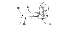
搬送方向がF1で示される第1コンベヤ2は、添付製品1を供給するためのもので、添付製品1は、粘着層1c によってキャリアバンド3上に固定されている。この粘着層1cは、搬送方向F1に走行するストリップの形式で添付製品1の左側縁部に設けられている。キャリアバンド3は、スピンドル4a を用いて取り付けられた供給ロールから巻戻され、偏向ローラ4b、4c、4dの回りに案内されて受入位置A1に至る。この受入位置では、キャリアバンドは、鋭角で分離端部5の回りに案内され、その結果、添付製品1は、キャリアバンド3から分離されて供給方向F1に進む。添付製品1と分離したキャリアバンド3は、供給方向F1とは反対の方向F2に引き出されて処分される。
【0018】
搬送装置10の搬送速度に調和して動く添付製品1は、動的に移動でき、例えば、速度を低下させたり、中間で貯蔵されることなく、搬送装置10の保持要素20a,20b等に対して正確に移動することができる。これに対応して、第2コンベヤ100の搬送速度を搬送装置10の搬送速度に適合することが望ましい。その結果、スムーズな移動ができ、個々の装置間で添付製品1が実際にスローダウンすることがない。
【0019】
また、図7において、保持要素20aによって把握される前に、添付製品1は、支持要素7a上の中間基部に留まり、そして、ロッキング要素8によって保持される。このロッキング要素は、添付製品が保持要素20a(図11d参照)によって把握されていた対応する添付製品1を解放する。添付製品1上にある粘着層1cは、支持要素7a上に残る添付製品1の下面1bに配置される。
【0020】
支持要素7a上に供給される添付製品1は、保持要素20aによってその上面側1aを把握され、排出位置A2に対してx軸回りに搬送される。そして、添付製品1は、支持要素7b上に解放されて、添付製品1の下面1bと露出した粘着層1cが半径方向外側に置かれることになる。
【0021】
第1軸線xの回りの循環方向に駆動される保持要素20aは、第2軸線yの回りに回転できるように取り付けられる。この第2軸線yは、第1軸線xに対してほぼ垂直に配置され、保持要素20aを第1軸線xの回りに回転する。受入位置A1から排出位置A2への搬送中、添付製品1は、y軸線の回りに回転し、その結果、添付製品は、さらなる処理のために必要とされる位置における排出位置A2にある第2コンベヤ100の搬送クランプ6に排出することができる。
【0022】
本発明の実施形態では、添付製品1は、時計方向に90°回転し、その結果、粘着層1cが付着している添付製品1の端部が、排出位置A2にある第2コンベヤ100の搬送方向F3に対して後縁になる。
【0023】
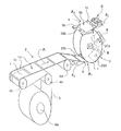
図1および図2に見られるように、搬送クランプ6は、添付製品1の後縁を把握し、図7および図10に示すように、添付製品1が処理装置1000および/またはこれに取りつけた印刷製品9に運ばれる。
【0024】
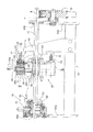
図3は、本発明の好ましい形状を示しており、関連する駆動部12,15および制御装置14が設けられている。図5は、図3に示すIV-IV線に沿って見た本発明の装置における断面を示している。この図から明らかなように、搬送装置10は、4つの保持要素20a,20b,20c,20dを有し、これらの要素は、吸引ツールまたはサッカー(吸盤)として構成され、各々は、軸線yの回りに回転でき、かつ駆動軸11の軸線xに対して垂直に配置される支持本体22に取り付けられている。支持本体22は、回転ディスク28に連結される。また、適切ならば、支持本体は、フランジハブ25を用いて第1軸線xに沿って配置された軸11上に固定されたロータアームに連結される。フランジハブ25に連結された支持本体22とロータディスク28は、軸11によって駆動されるロータ27を形成する。
【0025】
サッカーとして構成される保持要素20a,20b,20c,20d は、2つの軸受23a,23bを用いて、支持本体22に回転可能に取り付けられている中空軸21を有する。この中空軸21は、エア通路56を有し、エア通路の半径方向外側の端部には添付製品1を把握するのに適する吸引連結部24が設けられている。また、エア通路の反対側の端部は第1軸線xの方向に向き、エジェクタ55内に挿入されている。エジェクタ55は、制御可能な圧縮空気装置15に空気圧で連結され、吸引および排気動作を有するジェットポンプとして作用する。圧縮空気装置15は、軸11上に設けた回転バルブ53を含み、この回転バルブは、1つの空気圧ライン54を介して1つのエジェクタ55に連結されている。また、回転バルブ53は、空気供給がステータ51内で起こるように軸受52を用いてステータ51に対して回転可能に取り付けられている。また、回転バルブ53内には、各保持要素20a,20b,20c,20d のためのエア通路が形成されている。
【0026】
各中空軸21内の空気圧(真空)は、保持要素20a,20b,20c,20d の位置に従って制御される。その結果、添付製品1は、受入位置A1で吸引により保持され、それに続き搬送されて、排出位置A2において解放される。上記圧縮空気装置の代わりに、流速を増加させることによりエジェクタ55内に必要な吸引作用が生じることによって負圧システムを用いることが可能となり、この負圧を用いて、必要とする通路からの吸引によってエアが吹き出される。
【0027】
図6aは、図3のV‐V線に沿って分割して見た本発明に係る搬送装置を示す。ここに詳細に示される制御装置14は、各保持要素20a,20b,20c,20dに対してスライド32とガイド手段40を有する。スライド32は、保持要素の支持本体22に対して変位可能に取り付けられ、スライドとガイド手段は、互いに接触している。そのため、スライド32のホイール31はガイド手段40の表面をたどりながら移動する。
【0028】
この場合、スライド32は、中空軸21上に設けられた放射状の歯形状でかみ合う歯形を有する。第1軸線xに対して平行にスライド32が変位することにより、中空軸21の回転が生じ、その回転に基づいて、各保持要素20a,20b,20c,20d を回転することが可能になる。スライド32は、ガイド手段40の表面に従って変位し、これにより、各保持要素20a,20b,20c,20d の回転は、軸11の回転角度に従って所定の位置で生じる。ガイド手段40は、ロータ27の回転表面に平行に配置されている取付パネル41に固定され、また、少なくとも1つの荷重支持要素42(図4には、2つの荷重支持要素42a,42bが示されている。)を介して荷重支持構造体18に連結されている。
【0029】
荷重支持構造体18は、ベース要素82を有し、このベース要素上に荷重支持要素42a,42bと2つの支持要素81a、82bが固定されている。これらの支持要素は、軸11を取りつけるために役立つ軸受83a,83bを有する。さらに、軸駆動部12の一部が支持要素81b(図3および図5参照)上に固定されている。
【0030】
図7に示された第2コンベヤ100は、ヨーロッパ特許明細書EP0675062B1に詳細に示されており、ここには、前後に順次配置される個々に制御可能な搬送クランプ6を備え、循環方向に駆動され、各々の搬送クランプには、2つのクランプ要素686,688が設けられている。これらのクランプ要素は、循環経路の受入部分において、ほぼ循環方向Uに向いたクランプ口614を形成している。
【0031】
搬送装置10の排出位置A2での受入部分において、各搬送クランプ6により、各々1つの添付製品1がその後縁を把握され、循環方向Uに見るように、また、図10に示すように、処理装置1000に設けた壁要素1001上に跨る形で配置された印刷製品9上に排出される。
【0032】
本発明の搬送装置10を用いて、第1コンベヤから第2コンベヤ2,100への添付製品1の搬送は、図11a〜図11dを参照して説明する。添付製品1を備えるキャリアバンド3は、上述したように、鋭角で分離端部5の回りに案内され、その結果、添付製品1が分離されて受入位置A1(図11a参照)において第1支持要素7a上に置かれる。つぎに続く保持要素20aによって添付製品1が受け取られるまで、第1支持要素7a上に置かれた添付製品1は、ロック要素8によって保持されている(図11bのbを参照)。添付製品1が保持要素20a(図11cのcを参照)によって把握されると、この添付製品1は、下方に旋回する(図11dのdを参照)ロック要素8によって解放される。
【0033】
受入位置A1と排出位置A2の間の搬送中、把握された添付製品1は、粘着層1cを有する添付製品1の端縁がロータ27の回転方向に対して後縁となるまで、制御装置14によって第2軸線yの回りに回転する。
【0034】
図11aにおけるeにおいて、保持装置20cは、排出位置A2に到達し、そこで、搬送された添付製品1を第2支持要素7b(図11bのfと図11cのgを参照)上に置く。添付製品1が第2支持要素7bの上に配置されると、保持要素20c(図11dのhを参照)が添付製品1を解放する。その結果、図11aから図11cにおけるi 、j、kで示すように、添付製品1は、搬送クランプ6によって把握されかつ案内される。
【0035】
図12a〜12dは、例えば、図10で示すように、印刷製品9に連結される添付製品1を供給および準備する方法を示す。添付製品1のためのキャリアバンド3の代わりに、図12a,12bに示すように、一端部に粘着層1c’を有して搬送方向に連続して走行するバンド3’を用いることができる。受入位置の上流側で、バンド3’は、切断装置90によって添付製品1’に分割され、搬送動作に続いて印刷製品9に連結される。即ち、添付製品は、回転しない搬送装置10を介して移動する。
【0036】
図12dでは、搬送動作中、添付製品1’は、本発明に従う搬送装置10を用いて、所望の位置となるように回転する。図12cと図12dは、粘着層を有していないバンド3”を示し、切断装置90によって分割され、粘着剤分配器91,92および/または印刷ヘッド93(例えば、インクジェット)を用いて粘着性被膜が添付製品1”に形成される。この添付製品は、例えば、バンド3”を形成するために一緒に結合されるトレードサンプル(trade sample)またはサンプルパックとすることができる。
【0037】
図12dからわかるように、印刷製品9は、処理装置1000において、異なる方法で取り付けることができる添付製品1を備えることになる。本発明の搬送装置10は、印刷製品をマウントするために必要な位置に添付製品1を供給することができるので、部分的ではなく多用途に使用でき、かつ機能的に使用することができる。添付製品1は、所望の角度で第2軸線yの回りに回転でき、印刷製品9に連結することができる。この印刷製品は、受け入れギャップ内に挿入され、壁要素上に跨る形で集められ、または搬送ベルト上に配置され、処理装置1000に取り付けられる。
【0038】
添付製品1が搬送装置10を介して走行するとき、添付製品1の位置の必要な変更、即ち、所定の角度でかつ所定の回転方向で第2軸線yの回りに回転することが、ガイド手段40の形状によって決定される。添付製品1が、回転しないで搬送装置10を介して走行するようになっている場合、その時、例えば、図4に示すように、ガイド手段40が、図4の一点鎖線によって示される位置から離れて、第1軸線xの方向に調整されて、実線によって示す位置に移動する。そして、ガイド手段のホイール31は、係合領域から離れ、その結果、受入位置A1から排出位置A2に添付製品1を搬送中、添付製品1は、第2軸線yの回りに回転しない。しかし、ガイド手段40を、図4に示された2つの制限位置間の中間位置に保持することが可能である(一点鎖線−最大回転、例えば、90°、実線は、非回転)。その結果、添付製品1に対する所定の角度は減少する。
【0039】
図4に示す実施形態において、ガイド手段40に連結されている取付パネル41は、負荷軸受要素42’上に設けられ、この軸受要素は、一方で、軸11上を変位できるように配置され、他方で、軸11に対して平行なガイドロッド96上で変位できるように配置されている。ガイドロッド96は、ベース要素82に連結する支持要素81b,81cによって支持されている。ガイド手段40を有する取付パネル41の調整のために、制御シリンダ97が取付パネル41と支持要素81bとの間に配置されている。
【0040】
図6aに示す変形例において、スライダ32がホイール31を介してガイド手段40と相互作用し、キャッチ98を用いて、保持要素20の所定の回転角度に対応する所定位置に抑止することができる。このキャッチ98は公知のもので、ホイール31がガイド手段40からはずれてもこの位置に留めることができる。制御要素99を用いて、キャッチ98は、図6aの一点鎖線で示す位置に調整することができ、キャッチ98の開口98'とスライド周囲との間のクランプ操作により生じるブロッキングをなくすことができる。これにより、制御要素99を用いて、個々に回転または非回転を選択できることになる。また、ガイド手段40の作動領域が搬送領域の外側に位置するように軸11の回りの取付パネル41上でガイド手段40を回転させることも考えられる。
【0041】
図4および図6bに従う設計では、スイッチをオン・オフさせて、即ち、制御装置14を切り替えることができ、その結果、添付製品1は、搬送装置10によって、回転または回転しないで、所定の調整可能な角度に正確に合わせて走行することができる。
【0042】
さらに、搬送装置10が、4つの保持要素20a、・・・よりも少ない数、または多い数の保持要素を備えることも可能である。保持要素20の数量は、添付製品1の大きさを考慮して選択することが望ましい。
【0043】
図8および図9に示すように、保持要素20を吸引ツールとして構成し、支持本体22に各保持要素を取り付けることが可能であり、そして、保持要素は、図5で用いられるロータ27ではなくて、連続する循環経路を有する循環コンベヤ127に割り当てられるように、軸線yの回りに回転させることができる。この場合、添付製品1を搬送する保持要素20の回転移動は、スイッチのオンオフおよび/またはスイッチの切り替えが可能なガイド手段(図示略)により制御される。
【0044】
図8に示す循環コンベヤ127の配置において、添付製品1は、循環コンベヤの底部領域において、添付製品1の上面が保持要素20により把握され、そして、ロータ27の場合と同様に、循環コンベヤ127によって添付製品の下面が上側に向く。
【0045】
循環経路に直交する軸線yの回りに添付製品1を回転することは、偏向動作の前に、例えば、図8において、参照番号20aで示された保持要素の回転によって行なわれる。図9に示す循環コンベヤ127の配置において、添付製品1は、その下面が循環コンベヤの上面領域で把握される。そして、添付製品1の下面が支持要素7b上に解放され、添付製品1は、(例えば、保持要素20bの回転により)所定の回転角度で前もって回転させることが可能である。
【0046】
もちろん、本発明に係る搬送装置10は、受入位置に積層された状態に置かれた添付製品1を搬送する場合にも用いることができる。この場合、個々の添付製品1は、補助的ツールにより、持ち上げられ、付加的なサッカーまたは、切断カッタ、あるいは保持要素20a,20b,20c,20d によって直接把握される。
【0047】
こうして、添付製品1、1’,1”が、所望の第1コンベヤ装置2,2’,2”によって供給されかつ準備され、さらに、本発明の搬送装置により必要な位置に移動され、さらに所望の第2コンベヤ装置100,1000によって処理される。
【0048】
有効に搬送するために、粘着層を設けない添付製品を使用して、所定の位置に本発明の搬送装置10によって移動することもできる。添付製品は、比較的軽量の印刷物であることが望ましく、例えば、ポスト−イット製品、内容物が満たされたトレードサンプルまたは情報リーフレットが、印刷製品に結合される。
【0049】
すでに述べたように、搬送装置10は、第1,第2コンベヤに同期しているのが望ましく、添付製品1がスムーズに搬送することができる。もちろん搬送された添付製品1は、搬送装置10によって排出位置A2にある印刷製品あるいは他の製品に直接設けることもできる。
【0050】
さらに、粘着剤を被膜してない添付製品1を搬送することもでき、また印刷製品あるいは他の製品の中に挿入することもできる(例えば、新聞における広告リーフレット等)。
【図面の簡単な説明】
【図1】第1コンベヤによって供給され、適当な場所でその位置を変更して順次移動する添付製品が、第2コンベヤの搬送クランプによって把握されるようになっている、本発明に係る搬送装置の斜視図である。
【図2】添付製品を把握するときの、図1に示す搬送クランプの側面図である。
【図3】駆動および制御装置を有する本発明の搬送装置における一部断面図である。
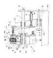
【図4】図3に関連した制御装置の第2変形例を示す一部断面図である。
【図5】図3のIV‐IV線に沿って分割して見た、本発明に係る搬送装置の一部側断面図である。
【図6】図6aは、図3のV-V線に沿って分割して見た、本発明に係る搬送装置の一部断面図であり、図6bは、制御装置の第3変形例として図5に対応する一部断面図である。
【図7】第1コンベヤから添付製品を受取り、それを第2コンベヤに排出する構成を示す図である。
【図8】第1コンベヤの第2変形例として、図7に対応する概略構成図である。
【図9】第1コンベヤの第3変形例として、図7に対応する概略構成図である。
【図10】印刷製品の中に添付製品を設けるように、処理装置と相互作用する図7の搬送装置を示す図である。
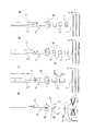
【図11】11a〜11dは、添付製品の搬送における異なる局面での図7の搬送装置を示す図である。
【図12】12a〜12dは、添付製品の準備と、それに続く添付製品を処理装置に置かれた印刷製品に組み入れるための装置を示す図である。
【符号の説明】
1 添付製品
2 第1コンベヤ
3、3’、3” バンド
6 搬送クランプ
7a、7b 支持要素
9 印刷製品
10 搬送装置
12,15 駆動部
14 制御装置
20a,20b,20c,20d 保持装置
21 中空軸
22 支持本体
27 ロータ
32 スライド
40 ガイド手段
54 ライン
55 エジェクタ
100 第2コンベヤ[0001]
BACKGROUND OF THE INVENTION
The present invention relates to an apparatus and a method for transporting a sheet-like attached product having an adhesive layer from a receiving position to a discharging position, in accordance with the preamble of the main independent claim.
[0002]
[Prior art]
During processing, particularly when assembling printed products, supplementary products such as labels, trade samples or post-it® products are typically provided in or on the printed product. It is. For example, the attached product is used by being peeled off from a band or a strip which is present in a stack or in a roll form. The band becomes a carrier band, and the attached product attached to the band is pulled away from the band during a transport operation, and is grasped by a general apparatus and is transported to a discharge position. Then apply directly to the printed product or, if appropriate, use additional tools. However, the strip or band forms the base of the attached product, from which the attached product can be peeled off and, if appropriate, further processing and adhesive can be applied.
[0003]
When the attached product to be supplied requires an adhesive layer, this adhesive layer is usually provided on the strip-type attached product in a direction transverse to the conveying direction. This is because the operation of continuously adhering the adhesive strip to the band in the longitudinal direction is required to have an accuracy in which the adhesive strip is arranged more straightly than the adhesive strip is adhered in the lateral direction. Furthermore, it must be synchronized with the cutting tool. Even when a carrier band is used, the attached product attached to the carrier band is preferably provided with a strip-shaped adhesive layer in a direction transverse to the conveying direction. As soon as the carrier band is guided at, for example, an acute angle, the attached product with the strip-shaped adhesive layer attached is continuously fed in the conveying direction while being separated from the carrier band during processing. .
[0004]
The operation of supplying the attached product with the adhesive strip in the lateral direction is advantageous, whereas such attached product can be correctly attached to the printed product with high expense. Therefore, it is a common practice to use a device that changes the transport direction of the attached product within the range of the transport operation. As a result, according to this change, the edge adhering to the adhesive strip moves along the new transport direction.
[0005]
Such a device is disclosed in International Patent Publication No.
[0006]
The separated attached product is supplied to the rotor by suction means or rollers. The rotor uses grasping elements or suction elements to grasp the attached product transversely to the supply direction and / or longitudinal direction and guide it to the discharge position, where it connects the attached product to the printed product, Release the attached product.
[0007]
In this case, the direction of conveyance of the attached product on the conveyor is positioned perpendicular to the plane in which the attached product grasped in the lateral direction is conveyed by the rotor. Further, the conveyance direction of the attached product is also perpendicular to a plane in which the printed product that will be provided with the attached product passes through the rotor and is guided in the tangential direction. The attached product provided with the strip-shaped adhesive layer in a direction transverse to the moving direction of the conveyor is grasped by the rotor, and as a result, the edge portion of the attached product contacts the adhesive layer of the strip, and the circulation direction of the rotor Is located at the trailing edge.
[0008]
However, according to International Patent Publication No.
[0009]
Due to the change of the transport direction within the transport operation, furthermore, the individual transport procedures have to be carried out with high accuracy, so that it is not expensive to increase the transport speed of the device. I do not get.
[0010]
[Problems to be solved by the invention]
In view of such circumstances, an object of the present invention is to provide an apparatus and a method for conveying a sheet-like attached product as a high-functional conveying apparatus that can specify processing in a wide range. As a result, the attached product is supplied to the first position by the first conveyor and is grasped and conveyed to the second conveyor, where the attached product is discharged to the second position so that further appropriate processing can be performed. Become.
[0011]
[Means for Solving the Problems]
In order to achieve the above object, the present invention has the structure described in each claim. The present invention is an apparatus for transporting a sheet-like attached product having an adhesive layer in particular from a receiving position to a discharging position, wherein a first conveyor provided at the receiving position and a second conveyor provided at the discharging position are Can be selected in the desired direction, and a change in the position of the attached product is required for delivery to the second conveyor.
[0012]
For this purpose, the device according to the invention is movable along a continuous circulation path so that the attached product is grasped in the receiving position and released again in the discharge position, and is positioned substantially perpendicular to the circulation path. During transport of the holding element from the receiving position to the discharge position, the end position of the transported attached product is further processed for further processing. With the action of selectively switching whether the holding element remains unchanged at a rotational position or the holding element is rotated about an axis y until a position to be encountered is reached. With control device The Including The control device has adjustable guide means and a slide, the slide being connected to the holding element and being movable, and contacting the surface of the guide means during the movement of the holding element. And is configured such that the displacement of the slide causes a corresponding rotation of the holding element. It is characterized by that.
[0013]
According to a preferred embodiment of the invention, the conveying direction of the first conveyor and / or the second conveyor and the conveying direction of the conveying device are arranged on the same plane, so that there is a need along the conveyor on which the printed product is provided. Space is minimized. The entire transport operation of the present invention can occur in one transport direction or at least one plane. Therefore, individual conveying device while The handling of the movement becomes easy. In addition, the apparatus can be realized at a low cost and a high conveyance speed.
[0014]
DETAILED DESCRIPTION OF THE INVENTION
Embodiments of the present invention will be described with reference to the drawings. FIG. 1 shows a schematic view of a
[0015]
In FIG. 10, the attached
[0016]
The conveyance direction of the first and
[0017]
The
[0018]
The attached
[0019]
Also, in FIG. 7, before being grasped by the holding
[0020]
The attached
[0021]
The holding
[0022]
In the embodiment of the present invention, the attached
[0023]
As can be seen in FIGS. 1 and 2, the
[0024]
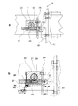
FIG. 3 shows the preferred shape of the present invention, in which the associated
[0025]
The holding
[0026]
The air pressure (vacuum) in each
[0027]
FIG. 6a shows the conveying device according to the invention as seen divided along the line VV in FIG. The
[0028]
In this case, the
[0029]
The
[0030]
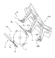
The
[0031]
In the receiving portion of the
[0032]
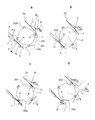
The conveyance of the attached
[0033]
During the conveyance between the receiving position A1 and the discharge position A2, the grasped
[0034]
In e in FIG. 11a, the holding
[0035]
12a to 12d show a method for supplying and preparing an
[0036]
In FIG. 12d, during the transfer operation, the attached
[0037]
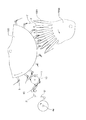
As can be seen from FIG. 12d, the printed
[0038]
When the attached
[0039]
In the embodiment shown in FIG. 4, the mounting
[0040]
In the variant shown in FIG. 6 a, the
[0041]
In the design according to FIGS. 4 and 6b, the
[0042]
Furthermore, it is also possible for the
[0043]
As shown in FIGS. 8 and 9, it is possible to configure the holding
[0044]
In the arrangement of the
[0045]
The rotation of the
[0046]
Of course, the
[0047]
In this way, the attached
[0048]
In order to convey effectively, the attachment apparatus which does not provide an adhesion layer can be used, and it can also move to the predetermined position with the conveying
[0049]
As already described, it is desirable that the conveying
[0050]
Furthermore, the attached
[Brief description of the drawings]
FIG. 1 is a conveying device according to the present invention in which an attached product supplied by a first conveyor and moved in sequence at an appropriate location is grasped by a conveying clamp of a second conveyor. FIG.
FIG. 2 is a side view of the conveyance clamp shown in FIG. 1 when grasping an attached product.
FIG. 3 is a partial cross-sectional view of a transfer device according to the present invention having a drive and control device.
FIG. 4 is a partial cross-sectional view showing a second modification of the control device related to FIG. 3;
5 is a partial cross-sectional side view of the transport device according to the present invention, viewed along line IV-IV in FIG.
6A is a partial cross-sectional view of the transport apparatus according to the present invention, divided along the line VV in FIG. 3, and FIG. 6B is a third modified example of the control apparatus shown in FIG. FIG.
FIG. 7 is a diagram showing a configuration for receiving an attached product from a first conveyor and discharging it to a second conveyor.
FIG. 8 is a schematic configuration diagram corresponding to FIG. 7 as a second modified example of the first conveyor.
FIG. 9 is a schematic configuration diagram corresponding to FIG. 7 as a third modification of the first conveyor.
10 shows the transport device of FIG. 7 interacting with the processing device to provide an attached product in the printed product.
11a to 11d are views showing the transport device of FIG. 7 in different situations in transport of attached products.
FIGS. 12a to 12d are diagrams showing an apparatus for preparing an attached product and subsequently incorporating the attached product into a printed product placed in a processing apparatus.
[Explanation of symbols]
1 Attached product
2 First conveyor
3, 3 ', 3 ”band
6 Transport clamp
7a, 7b Support element
9 Printing products
10 Transport device
12, 15 Drive unit
14 Control device
20a, 20b, 20c, 20d holding device
21 Hollow shaft
22 Support body
27 Rotor
32 slides
40 Guide means
54 lines
55 Ejector
100 Second conveyor
Claims (18)
前記添付製品が受入位置(A1)において把握されかつ排出位置(A2)において再び解放されるように、連続した循環経路に沿って移動可能であり、かつ前記循環経路にほぼ垂直に位置する軸線yの回りに回転できるように取り付けられた、少なくとも1つの保持要素(20a,20b,20c,20d)と、
前記受入位置から前記排出位置への前記保持要素(20a,20b,20c,20d)の搬送中に、搬送された前記添付製品(1)の端部位置が、更なる処理に直面する位置に到達するまで、前記保持要素をある回転位置でその位置を変更しないままにするか、または前記保持要素を所定の角度で軸線yの回りに回転させるかを選択的に切り替える動作を備えた制御装置(14)とを含み、
前記制御装置(14)は、調整可能なガイド手段(40)とスライド(32)を有し、該スライド(32)は、前記保持要素(20a,20b,20c,20d)に連結されて移動でき、かつ前記保持要素(20a,20b,20c,20d)を移動中、前記ガイド手段(40)の表面に接触することによって前記循環径路に沿って変位でき、このスライド(32)の変位により、前記保持要素(20a,20b,20c,20d)の対応した回転が生じるように構成されていることを特徴とする装置。An apparatus for conveying the discharge position the sheet accompanying the product (1) from the receiving position (A1) (A2) having a viscosity adhesive layer (10),
An axis y that is movable along a continuous circulation path and is positioned substantially perpendicular to the circulation path so that the attached product is grasped at the receiving position (A1) and released again at the discharge position (A2). At least one retaining element (20a, 20b, 20c, 20d) mounted for rotation about
It said retaining element to said discharge position from the receiving position (20a, 20b, 20c, 20d) during transport of the end portion position of the attachment products that are transported (1) is, reaches a position to face the further processing A control device having an operation of selectively switching whether to keep the holding element unchanged at a certain rotational position or to rotate the holding element about an axis y until a predetermined angle ( 14) and a,
The control device (14) has adjustable guide means (40) and a slide (32), the slide (32) being connected to the holding element (20a, 20b, 20c, 20d) and movable. And while moving the holding element (20a, 20b, 20c, 20d), it can be displaced along the circulation path by contacting the surface of the guide means (40), and the displacement of the slide (32) A device characterized in that it is adapted to cause a corresponding rotation of the holding elements (20a, 20b, 20c, 20d) .
前記添付製品(1)が受入位置(A1)において保持要素(20a,20b,20c,20d)によって把握されかつ排出位置(A2)において再び解放されるように、連続した循環経路に沿って移動可能であり、前記受入位置(A1)から排出位置(A2)への搬送中、前記保持要素(20a,20b,20c,20d)が前記循環経路にほぼ垂直に位置する軸線yの回りに回転できるように取り付けられ、
前記受入位置から前記排出位置への前記保持要素(20a,20b,20c,20d)の搬送中に、搬送された添付製品(1)の端部位置が、更なる処理に直面する位置に到達するまで、前記保持要素をある回転位置でその位置を変更しないままにするか、または前記保持要素を所定の角度で軸線yの回りに回転させるかを選択的に切り替え、
前記保持要素(20a,20b,20c,20d)に連結されて移動するスライド(32)が、前記保持要素(20a,20b,20c,20d)の移動中、前記ガイド手段(40)の表面に接触することによって循環径路に沿って変位でき、このスライド(32)の変位により、前記保持要素(20a,20b,20c,20d)の対応した回転が生じるように構成されていることを特徴とする方法。A method for conveying a sheet-like attachment product (1) from the receiving position (A1) to the discharge position (A2) having a viscosity adhesive layer,
Movable along a continuous circulation path so that the attached product (1) is grasped by the holding elements (20a, 20b, 20c, 20d) in the receiving position (A1) and released again in the discharge position (A2) So that the holding element (20a, 20b, 20c, 20d) can rotate around an axis y positioned substantially perpendicular to the circulation path during conveyance from the receiving position (A1) to the discharging position (A2). Attached to the
During the transport of the holding element (20a, 20b, 20c, 20d) from the receiving position to the discharge position, the end position of the transported attached product (1) reaches a position where it faces further processing. Until the holding element is left unchanged in a certain rotational position, or the holding element is selectively switched about rotating around the axis y by a predetermined angle,
The slide (32) that moves while being connected to the holding element (20a, 20b, 20c, 20d) contacts the surface of the guide means (40) during the movement of the holding element (20a, 20b, 20c, 20d). The method is characterized in that it can be displaced along the circulation path, and that the displacement of the slide (32) causes a corresponding rotation of the holding elements (20a, 20b, 20c, 20d). .
Applications Claiming Priority (2)
| Application Number | Priority Date | Filing Date | Title |
|---|---|---|---|
| CH224199 | 1999-12-07 | ||
| CH19992241/99 | 1999-12-07 |
Publications (2)
| Publication Number | Publication Date |
|---|---|
| JP2001206586A JP2001206586A (en) | 2001-07-31 |
| JP4761237B2 true JP4761237B2 (en) | 2011-08-31 |
Family
ID=4229161
Family Applications (1)
| Application Number | Title | Priority Date | Filing Date |
|---|---|---|---|
| JP2000371377A Expired - Fee Related JP4761237B2 (en) | 1999-12-07 | 2000-12-06 | Apparatus and method for conveying attached product in sheet form |
Country Status (9)
| Country | Link |
|---|---|
| US (1) | US6520496B2 (en) |
| EP (1) | EP1106550B1 (en) |
| JP (1) | JP4761237B2 (en) |
| AT (1) | ATE259747T1 (en) |
| AU (1) | AU775822B2 (en) |
| CA (1) | CA2327774C (en) |
| DE (1) | DE50005320D1 (en) |
| DK (1) | DK1106550T3 (en) |
| ES (1) | ES2211440T3 (en) |
Families Citing this family (8)
| Publication number | Priority date | Publication date | Assignee | Title |
|---|---|---|---|---|
| EP1683612B1 (en) * | 2005-01-21 | 2016-08-03 | Ferag AG | Method and device for transporting flexible flat products, and for cutting them at the same time |
| CH711986B1 (en) | 2006-10-13 | 2017-06-30 | Ferag Ag | Method and system for individualizing a printed product. |
| CH705738A1 (en) | 2011-11-11 | 2013-05-15 | Ferag Ag | A method for applying flat supplementary products of basic products, as well as apparatus for carrying out the method. |
| US9061832B2 (en) * | 2011-11-21 | 2015-06-23 | R.A. Jones & Co. | Pouch transfer apparatus and methods |
| US8939445B2 (en) * | 2013-05-30 | 2015-01-27 | Kimberly-Clark Worldwide, Inc. | Vacuum roll with internal rotary valve |
| JP6721624B2 (en) * | 2018-03-27 | 2020-07-15 | ファナック株式会社 | Label attaching device with label removing function, robot, and label removing method |
| CN110304438A (en) * | 2019-07-22 | 2019-10-08 | 黄山富田精工制造有限公司 | Feeding component and feeding robot using the component |
| CN120024696B (en) * | 2025-04-22 | 2025-07-22 | 四川新途流体控制技术有限公司 | An automated system for safe handling of gas cylinders |
Family Cites Families (22)
| Publication number | Priority date | Publication date | Assignee | Title |
|---|---|---|---|---|
| US2108280A (en) * | 1937-05-08 | 1938-02-15 | Diamond Match Co | Machine for packing book matches |
| CH599891A5 (en) * | 1975-07-30 | 1978-06-15 | Sapal Plieuses Automatiques | |
| CH627997A5 (en) * | 1978-03-23 | 1982-02-15 | Ferag Ag | Device for forming a continuous branch stream from a main stream of continuously occurring flat products, in particular printed products |
| DE2901800A1 (en) * | 1979-01-18 | 1980-07-24 | Becker & Van Huellen | METHOD AND DEVICE FOR CONTROLLING THE BOTTOM OF PLATE-SHAPED OBJECTS |
| US4394898A (en) * | 1981-04-23 | 1983-07-26 | Paper Converting Machine Company | Method and apparatus for providing balanced stacks of diapers |
| JPS60153378U (en) * | 1984-03-16 | 1985-10-12 | 富士通株式会社 | Media rotation mechanism |
| US4608115A (en) * | 1984-04-23 | 1986-08-26 | Kimberly-Clark Corporation | Revolving transfer roll |
| US4696715A (en) * | 1986-02-11 | 1987-09-29 | Mgs Machine Corporation | Pick-and-place glue applicator |
| DE3605534A1 (en) * | 1986-02-20 | 1987-08-27 | Rotaprint Gmbh | BOW CONVEYOR FOR BOW PROCESSING MACHINES |
| US4787953A (en) * | 1987-01-12 | 1988-11-29 | Hobart Corporation | Apparatus for label transfer |
| JPH0331145A (en) * | 1989-06-28 | 1991-02-08 | Canon Inc | Sheet material endless conveyance device |
| US5104116A (en) * | 1990-04-06 | 1992-04-14 | Kimberly-Clark Corporation | Applicator apparatus and process for rotating and placing a strip of material on a substrate |
| EP0570339A1 (en) * | 1992-05-13 | 1993-11-18 | Grapha-Holding Ag | Device for adding inserts by adhesive |
| JP3348119B2 (en) * | 1993-10-04 | 2002-11-20 | 富士写真フイルム株式会社 | Label sticking apparatus and label mount used therefor |
| US5447219A (en) * | 1993-12-06 | 1995-09-05 | Cloud Corporation | Positioning mechanism for high speed packaging machinery |
| US5535999A (en) * | 1994-03-11 | 1996-07-16 | Axia Incorporated | Apparatus for rotating a flat article through a desired angular orientation |
| DE59501115D1 (en) | 1994-03-24 | 1998-01-29 | Ferag Ag | Device for feeding flat products to a processing device for printed products |
| US5740900A (en) * | 1995-07-20 | 1998-04-21 | Heidelberger Druckmaschinen Ag | Apparatus for splitting a product stream |
| US6116317A (en) * | 1996-06-21 | 2000-09-12 | Tharpe, Jr.; John M. | Apparatus having a core orientor and methods of orienting portions of a disposable undergarment |
| NL1006706C2 (en) | 1997-08-01 | 1999-02-02 | Vianen De Binderijgroep Bv | METHOD AND APPARATUS FOR APPLYING SHEETS OF MATERIAL INTO A ROWS OF MOVEMENTS |
| IT1294334B1 (en) * | 1997-08-20 | 1999-03-24 | Sitma Spa | DEVICE FOR ROTATING A LABEL DELETED IN A LABELING MACHINE |
| NL1012982C2 (en) * | 1999-04-29 | 2000-11-06 | Kl Ckner Honsel Tevopharm B V | Rotatable gripper device. |
-
2000
- 2000-11-24 EP EP00125755A patent/EP1106550B1/en not_active Expired - Lifetime
- 2000-11-24 AT AT00125755T patent/ATE259747T1/en active
- 2000-11-24 DK DK00125755T patent/DK1106550T3/en active
- 2000-11-24 DE DE50005320T patent/DE50005320D1/en not_active Expired - Lifetime
- 2000-11-24 ES ES00125755T patent/ES2211440T3/en not_active Expired - Lifetime
- 2000-12-06 US US09/731,233 patent/US6520496B2/en not_active Expired - Fee Related
- 2000-12-06 CA CA002327774A patent/CA2327774C/en not_active Expired - Fee Related
- 2000-12-06 JP JP2000371377A patent/JP4761237B2/en not_active Expired - Fee Related
- 2000-12-06 AU AU72063/00A patent/AU775822B2/en not_active Ceased
Also Published As
| Publication number | Publication date |
|---|---|
| ES2211440T3 (en) | 2004-07-16 |
| US20020125630A1 (en) | 2002-09-12 |
| AU7206300A (en) | 2001-06-14 |
| CA2327774C (en) | 2008-08-26 |
| DK1106550T3 (en) | 2004-03-15 |
| EP1106550A1 (en) | 2001-06-13 |
| ATE259747T1 (en) | 2004-03-15 |
| JP2001206586A (en) | 2001-07-31 |
| US6520496B2 (en) | 2003-02-18 |
| EP1106550B1 (en) | 2004-02-18 |
| AU775822B2 (en) | 2004-08-19 |
| CA2327774A1 (en) | 2001-06-07 |
| DE50005320D1 (en) | 2004-03-25 |
Similar Documents
| Publication | Publication Date | Title |
|---|---|---|
| CN108472824B (en) | Apparatus for manipulating substrates | |
| CN108472825B (en) | Apparatus and method for treating substrates | |
| US10328590B2 (en) | Device for treating substrates | |
| JPH02504132A (en) | labeling equipment | |
| JP4761237B2 (en) | Apparatus and method for conveying attached product in sheet form | |
| US20030127195A1 (en) | Labeling machine | |
| JP2001315732A (en) | Label sticking apparatus | |
| US11207881B2 (en) | Sheet processing machine with shaping device and upper suction transport means | |
| CN101772414A (en) | Sheet-fed printing press | |
| JP2009298595A (en) | Device and method for removing flat print product from pile and transferring the print product to transport device under operation | |
| JP5502704B2 (en) | Label sticking method and label sticking apparatus | |
| JP2003040511A (en) | Device for processing printed product supplied from stacking device | |
| US11208287B2 (en) | Sheet delivery unit, a sheet processing machine and a method for operating a sheet processing machine | |
| US6533016B2 (en) | Method and apparatus for joining supplementary products to printed products | |
| US11292680B2 (en) | Sheet feeder for a machine for processing material in sheet form, such as paper, cardboard or films | |
| JP4729192B2 (en) | Film feeder | |
| JP3544554B2 (en) | Label paper unloading mechanism | |
| US20060179988A1 (en) | Method and device for transporting flexible, two-dimensional products and simultaneously cutting these | |
| US7802780B2 (en) | Method and device for inserting flat articles into printed products | |
| JP4114998B2 (en) | Labeling device | |
| JP2013241277A (en) | Sheet conveyance device | |
| JP5824694B2 (en) | Sheet printer | |
| JPH03239592A (en) | Device for pasting small pieces onto signature printed books | |
| JPH11221979A (en) | Apparatus for attaching appendix | |
| HK1115843A (en) | Method and apparatus for turning a sheet during its transport through a printing press |
Legal Events
| Date | Code | Title | Description |
|---|---|---|---|
| A621 | Written request for application examination |
Free format text: JAPANESE INTERMEDIATE CODE: A621 Effective date: 20071003 |
|
| A977 | Report on retrieval |
Free format text: JAPANESE INTERMEDIATE CODE: A971007 Effective date: 20100730 |
|
| A131 | Notification of reasons for refusal |
Free format text: JAPANESE INTERMEDIATE CODE: A131 Effective date: 20100825 |
|
| A521 | Request for written amendment filed |
Free format text: JAPANESE INTERMEDIATE CODE: A523 Effective date: 20101122 |
|
| A01 | Written decision to grant a patent or to grant a registration (utility model) |
Free format text: JAPANESE INTERMEDIATE CODE: A01 Effective date: 20110511 |
|
| A01 | Written decision to grant a patent or to grant a registration (utility model) |
Free format text: JAPANESE INTERMEDIATE CODE: A01 |
|
| A61 | First payment of annual fees (during grant procedure) |
Free format text: JAPANESE INTERMEDIATE CODE: A61 Effective date: 20110527 |
|
| FPAY | Renewal fee payment (event date is renewal date of database) |
Free format text: PAYMENT UNTIL: 20140617 Year of fee payment: 3 |
|
| R150 | Certificate of patent or registration of utility model |
Free format text: JAPANESE INTERMEDIATE CODE: R150 |
|
| LAPS | Cancellation because of no payment of annual fees |