JP2013241277A - Sheet conveyance device - Google Patents

Sheet conveyance device Download PDF

Info

Publication number
JP2013241277A
JP2013241277A JP2013092014A JP2013092014A JP2013241277A JP 2013241277 A JP2013241277 A JP 2013241277A JP 2013092014 A JP2013092014 A JP 2013092014A JP 2013092014 A JP2013092014 A JP 2013092014A JP 2013241277 A JP2013241277 A JP 2013241277A
Authority
JP
Japan
Prior art keywords
sheet
cylinder
swing
unit
printing
Prior art date
Legal status (The legal status is an assumption and is not a legal conclusion. Google has not performed a legal analysis and makes no representation as to the accuracy of the status listed.)
Pending
Application number
JP2013092014A
Other languages
Japanese (ja)
Other versions
JP2013241277A5 (en
Inventor
Hayato Kondo
隼人 近藤
Current Assignee (The listed assignees may be inaccurate. Google has not performed a legal analysis and makes no representation or warranty as to the accuracy of the list.)
Komori Corp
Original Assignee
Komori Corp
Priority date (The priority date is an assumption and is not a legal conclusion. Google has not performed a legal analysis and makes no representation as to the accuracy of the date listed.)
Filing date
Publication date
Application filed by Komori Corp filed Critical Komori Corp
Priority to JP2013092014A priority Critical patent/JP2013241277A/en
Publication of JP2013241277A publication Critical patent/JP2013241277A/en
Publication of JP2013241277A5 publication Critical patent/JP2013241277A5/ja
Pending legal-status Critical Current

Links

Images

Classifications

    • BPERFORMING OPERATIONS; TRANSPORTING
    • B41PRINTING; LINING MACHINES; TYPEWRITERS; STAMPS
    • B41JTYPEWRITERS; SELECTIVE PRINTING MECHANISMS, i.e. MECHANISMS PRINTING OTHERWISE THAN FROM A FORME; CORRECTION OF TYPOGRAPHICAL ERRORS
    • B41J25/00Actions or mechanisms not otherwise provided for
    • B41J2025/008Actions or mechanisms not otherwise provided for comprising a plurality of print heads placed around a drum

Abstract

PROBLEM TO BE SOLVED: To provide a sheet conveyance device for conveying a sheet, which enables the size of the sheet to be changed with ease.SOLUTION: A sheet conveyance device 1 for conveying a sheet includes: a first conveyance part 39 which includes a first holder 39a for conveying the sheet by holding an end of the sheet; a second conveyance part 33 which includes second holders 33a-33c for conveying the sheet by holding the end of the sheet conveyed by the first conveyance part 39; a third conveyance part 31b which is swingably supported between the first and second conveyance parts 39 and 33, and which includes a third holder for holding the other end of the sheet having the one end held by the first holder 39a and transferring the other end of the sheet to the holders 33a-33c of the second conveyance part 33; and a control part which controls a swing motion of the third conveyance part 31b on the basis of the conveyance-direction length of the sheet.

Description

本発明は、シートを搬送するシート搬送装置に関する。   The present invention relates to a sheet conveying apparatus that conveys a sheet.

シートを搬送するシート搬送装置の一例として、シートの片面および両面に印刷を行うことができる反転機構付枚葉輪転印刷機に設けられたシート反転ユニットにおけるシート搬送装置がある(例えば、特許文献1参照)。この反転ユニットは、隣接する印刷ユニットの間に配設されシートを選択的に反転させることができ、これによりシートに片面印刷および両面印刷をすることが可能となっている。   As an example of a sheet conveying apparatus that conveys a sheet, there is a sheet conveying apparatus in a sheet reversing unit provided in a sheet-fed rotary printing press with a reversing mechanism capable of performing printing on one side and both sides of a sheet (for example, Patent Document 1). reference). The reversing unit is disposed between adjacent printing units and can selectively reverse a sheet, thereby enabling single-sided printing and double-sided printing on the sheet.

この特許文献1の反転機構付枚葉輪転印刷機では、反転ユニットが渡胴(特許文献1の第4図における図番17)と圧胴(特許文献1の第4図における図番16)とからなり、両面印刷を行う場合、渡胴によりシートの先端部をつかんだ状態で搬送されるシートの後端部を圧胴によりつかみ、当該シートの後端部を先頭として搬送するとともに当該シートの表裏を反転させることができるようになっている。   In this sheet-fed rotary printing press with a reversing mechanism of Patent Document 1, the reversing unit includes a transfer cylinder (number 17 in FIG. 4 of Patent Document 1) and an impression cylinder (number 16 in FIG. 4 of Patent Document 1). When performing double-sided printing, the rear end of the sheet conveyed while holding the leading end of the sheet by the transfer cylinder is grasped by the impression cylinder and conveyed with the trailing end of the sheet as the leading end. The front and back can be reversed.

特公平03−080108号公報Japanese Patent Publication No. 03-080108

しかしながらかかる特許文献1の反転機構付枚葉輪転印刷機では、シートのサイズを変更する場合、印刷装置を稼働させる前に圧胴を駆動させているギアの締結を断ち、圧胴のくわえ爪装置と渡胴に保持されたシートの後端部とが対向するように渡胴に対する圧胴の位相を変更した後、再度ギアを締結させるという作業を行なうため、作業者の負担や準備時間を要するという問題があった。   However, in the sheet-fed rotary printing press with a reversing mechanism disclosed in Patent Document 1, when changing the size of the sheet, before the printing apparatus is operated, the gear that drives the impression cylinder is cut off, and the gripper nail device of the impression cylinder And the rear end of the sheet held by the transfer cylinder are opposed to each other after changing the phase of the impression cylinder with respect to the transfer cylinder, and the work of refastening the gear is performed. There was a problem.

本発明はかかる問題を解決するためになされたものであり、シートのサイズ変更に容易に対応できるシート搬送装置を提案しようとするものである。   The present invention has been made to solve such a problem, and an object of the present invention is to propose a sheet conveying apparatus that can easily cope with a change in sheet size.

かかる課題を解決するため請求項1の発明においては、シートを搬送するシート搬送装置において、シートの端部を保持して搬送する第1保持装置を有する第1搬送部と、前記第1搬送部により搬送されるシートの端部を保持して搬送する第2保持装置を有する第2搬送部と、前記第1搬送部と前記第2搬送部との間で揺動自在に支持され、一方の端部が前記第1保持装置で保持されたシートの他方の端部を保持し、当該シートの他方の端部を前記第2搬送部の前記第2保持装置へ受け渡す第3保持装置を有する第3搬送部と、シートの搬送方向長さに基づいて前記第3搬送部の揺動動作を制御する制御部とを備えるようにする。   In order to solve this problem, in the invention according to claim 1, in the sheet conveying apparatus that conveys a sheet, a first conveying unit having a first holding device that conveys the sheet while holding an end of the sheet, and the first conveying unit A second conveying unit having a second holding device that holds and conveys an end of the sheet conveyed by the first conveying unit, and is swingably supported between the first conveying unit and the second conveying unit. A third holding device that holds the other end of the sheet held by the first holding device and delivers the other end of the sheet to the second holding device of the second transport unit; A third conveyance unit and a control unit that controls the swinging operation of the third conveyance unit based on the length of the sheet in the conveyance direction are provided.

請求項2の発明において、前記制御部は、前記第3保持装置の速度を、前記第1搬送部からシートを受け取るときに当該第1搬送部により搬送されるシートの速度と同速にし、前記第2搬送部へシートを受け渡すときに当該第2搬送部の前記第2保持装置の速度と同速にするように制御すると共に、前記第1搬送部からシートを受け取った後、前記第2搬送部へシートを受け渡すまでの間の前記第3搬送部の揺動速度をシートの搬送方向長に基づいて制御するようにする。   In the invention of claim 2, the control unit makes the speed of the third holding device the same as the speed of the sheet conveyed by the first conveying unit when receiving the sheet from the first conveying unit, When delivering the sheet to the second conveying unit, the second conveying unit is controlled to have the same speed as the second holding device, and after receiving the sheet from the first conveying unit, the second conveying unit The swing speed of the third conveying unit until the sheet is delivered to the conveying unit is controlled based on the length of the sheet in the conveying direction.

請求項3の発明において、前記第3搬送部の揺動速度を調整する調整部を備え、前記調整部は、前記第3搬送部の駆動系に設けられた差動歯車機構と当該差動歯車機構を駆動して前記第3搬送部の揺動速度を調整する調整モータとを有し、前記制御部は前記調整モータを制御するようにする。   The invention according to claim 3 further comprises an adjustment unit that adjusts a swing speed of the third transport unit, and the adjustment unit includes a differential gear mechanism provided in a drive system of the third transport unit and the differential gear. An adjustment motor that drives the mechanism to adjust the swing speed of the third transport unit, and the control unit controls the adjustment motor.

請求項4の発明において、前記第3搬送部を前記第1搬送部及び第2搬送部とは独立して揺動させる揺動用モータを備え、前記制御部は、前記揺動用モータを制御するようにする。   According to a fourth aspect of the present invention, there is provided a swinging motor that swings the third transport unit independently of the first transporting unit and the second transporting unit, and the control unit controls the swinging motor. To.

請求項1の発明によれば、シートサイズが変更された場合でも、その変更されたシートの搬送方向長さに基づいて第3搬送部の揺動動作を制御することができるので、シートサイズの変更されたシートの端部が到着するタイミングに合わせて第3搬送部の揺動動作の速度を変更し、当該第3搬送部により確実にシートを保持することができる。   According to the invention of claim 1, even when the sheet size is changed, the swinging operation of the third transport unit can be controlled based on the changed transport direction length of the sheet. The speed of the swinging motion of the third transport unit can be changed in accordance with the timing at which the changed end of the sheet arrives, and the sheet can be reliably held by the third transport unit.

デジタル印刷装置の全体構成を示す側面図である。It is a side view which shows the whole structure of a digital printing apparatus. 反転スイング装置の構成を示す側面図である。It is a side view which shows the structure of an inversion swing apparatus. 反転スイング装置のスイング機構を示す側面図である。It is a side view which shows the swing mechanism of an inversion swing apparatus. 反転スイング装置のスイング機構を展開したときの状態を示す断面図である。It is sectional drawing which shows a state when the swing mechanism of an inversion swing apparatus is expand | deployed. デジタル印刷装置の制御系の構成を示すブロック図である。It is a block diagram which shows the structure of the control system of a digital printing apparatus. デジタル印刷装置における印刷工程(1)を示す側面図である。It is a side view which shows the printing process (1) in a digital printing apparatus. デジタル印刷装置における印刷工程(2)を示す側面図である。It is a side view which shows the printing process (2) in a digital printing apparatus. デジタル印刷装置における印刷工程(3)を示す側面図である。It is a side view which shows the printing process (3) in a digital printing apparatus. デジタル印刷装置における印刷工程(4)を示す側面図である。It is a side view which shows the printing process (4) in a digital printing apparatus. デジタル印刷装置における印刷工程(5)を示す側面図である。It is a side view which shows the printing process (5) in a digital printing apparatus. 他の実施の形態における反転スイング装置のスイング機構を展開したときの状態を示す断面図である。It is sectional drawing which shows a state when the swing mechanism of the inversion swing apparatus in other embodiment is expand | deployed.

次に、本発明の一実施の形態について図面を参照して説明する。   Next, an embodiment of the present invention will be described with reference to the drawings.

<デジタル印刷装置の構成>
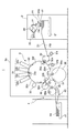
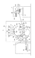
図1に示すように、シート搬送装置としてのデジタル印刷装置1は、供給部としての給紙装置2、処理部としてのデジタル印刷ユニット3及び排出部としての排紙装置4を備える。
<Configuration of digital printing device>
As shown in FIG. 1, a digital printing apparatus 1 as a sheet conveying apparatus includes a paper feeding device 2 as a supply unit, a digital printing unit 3 as a processing unit, and a paper discharge device 4 as a discharge unit.

給紙装置2には、複数のシートS1が積載された積載台21および、その積載台21の最上段のシートS1をフィーダボードFBへ搬送するサッカー装置23が設けられている。サッカー装置23は、第1吸23aおよび第2吸23bを備え、第1吸23aおよび第2吸23bが連続供給バルブ26および間欠供給バルブ27を介して負圧源25と接続されている。   The paper feeding device 2 is provided with a stacking table 21 on which a plurality of sheets S1 are stacked, and a soccer device 23 that conveys the uppermost sheet S1 of the stacking table 21 to the feeder board FB. The soccer device 23 includes a first suction 23 a and a second suction 23 b, and the first suction 23 a and the second suction 23 b are connected to the negative pressure source 25 through a continuous supply valve 26 and an intermittent supply valve 27.

連続供給バルブ26および間欠供給バルブ27は、共に第1吸23aおよび第2吸23bの負圧源25からの吸引を断接するものであるが、後述するように吸引を断接するタイミングがそれぞれ異なっている。   The continuous supply valve 26 and the intermittent supply valve 27 both connect and disconnect the suction from the negative pressure source 25 of the first suction 23a and the second suction 23b, but the timings for connecting and disconnecting the suction are different as will be described later. Yes.

フィーダボードFBのシート搬送方向先端側には、デジタル印刷ユニット3のフレーム3aに揺動自在に支持され、シートS1の一方の端部である先端(くわえ側端部)をくわえて保持する図示しないくわえ爪装置を備えたスイング装置31fが配設されている。スイング装置31fには給紙側渡し胴32が対向して配置され、その給紙側渡し胴32がフレーム3aに回転自在に支持されている。   On the front end side in the sheet conveying direction of the feeder board FB, it is supported by the frame 3a of the digital printing unit 3 so as to be swingable, and holds the front end (the end on the holding side) as one end of the sheet S1. A swing device 31f provided with a gripper device is provided. A paper feed side transfer drum 32 is disposed opposite to the swing device 31f, and the paper feed side transfer drum 32 is rotatably supported by the frame 3a.

給紙側渡し胴32には、スイング装置31fのくわえ爪装置により受け渡されるシートS1の先端をくわえた状態で保持するくわえ爪装置32aが設けられている。なおデジタル印刷ユニット3では、スイング装置31fおよび給紙側渡胴32により上流側シート搬送装置を構成している。   The feeding side transfer cylinder 32 is provided with a gripping claw device 32a that holds the leading end of the sheet S1 delivered by the gripping claw device of the swing device 31f. In the digital printing unit 3, the swing device 31f and the sheet feeding side transfer cylinder 32 constitute an upstream sheet conveying device.

給紙側渡し胴32には、スイング装置31fよりもシート搬送方向下流側に第2搬送部としての印刷胴33が対接配置され、その印刷胴33がフレーム3aに回転自在に支持されている。印刷胴33は、給紙側渡し胴32のくわえ爪装置32aからシートS1の先端を受け取って保持する第2保持装置としての印刷胴くわえ爪装置33a、33b、33cと、この印刷胴くわえ爪装置33a、33b、33cに対応して設けられシートS1を支持する支持面33d、33e、33fとを備え、本実施の形態においては、印刷胴くわえ爪装置と支持面との組が3組設けられた3倍胴として構成されており、その直径も給紙側渡し胴32の3倍の直径を有している。ここで、シートS1を保持する印刷胴くわえ爪装置33a、33b、33cは円周方向に互いに120度位相をずらした状態で設けられている。   A printing cylinder 33 as a second conveyance unit is disposed in contact with the sheet feeding-side transfer cylinder 32 downstream of the swing device 31f in the sheet conveyance direction, and the printing cylinder 33 is rotatably supported by the frame 3a. . The printing cylinder 33 is a printing cylinder holding claw device 33a, 33b, 33c as a second holding device that receives and holds the leading end of the sheet S1 from the holding claw device 32a of the feeding side transfer cylinder 32, and this printing cylinder holding claw device. 33a, 33b, 33c, and support surfaces 33d, 33e, 33f that support the sheet S1, and in this embodiment, three sets of the printing cylinder gripping nail device and the support surface are provided. Further, the diameter of the cylinder is three times that of the sheet feeding side transfer cylinder 32. Here, the printing cylinder holding claw devices 33a, 33b, and 33c that hold the sheet S1 are provided in a state in which the phases are shifted from each other by 120 degrees in the circumferential direction.

印刷胴33の支持面33d、33e、33fには複数の吸引用孔が形成されており、その複数の吸引用孔が負圧源と接続されている。この印刷胴33の給紙側渡し胴32との対接部分よりもシート搬送方向下流側には、当該印刷胴33の周面に対向してインクジェットノズル部34が配置されている。   A plurality of suction holes are formed in the support surfaces 33d, 33e, and 33f of the printing cylinder 33, and the plurality of suction holes are connected to a negative pressure source. An ink jet nozzle portion 34 is disposed on the downstream side of the printing cylinder 33 with respect to the sheet feeding side transfer cylinder 32 in the sheet conveying direction so as to face the peripheral surface of the printing cylinder 33.

インクジェットノズル部34には、互いに異なる色のインキをセットした複数のインクジェットノズルヘッド34a〜34dが印刷胴33の周面に沿ってシート搬送方向に並設され、それぞれが印刷胴33の周面を指向している。インクジェットノズルヘッド34a〜34dは、印刷胴33の支持面33d、33e、33fに全面吸着されたシートS1との隙間が僅かな間隔となるよう印刷胴33に近接して配設されている。なお、印刷胴33、インクジェットノズル部34によりシート印刷装置を構成している。   In the inkjet nozzle section 34, a plurality of inkjet nozzle heads 34a to 34d in which inks of different colors are set are arranged side by side along the circumferential surface of the printing cylinder 33 in the sheet conveying direction. Oriented. The inkjet nozzle heads 34a to 34d are arranged close to the printing cylinder 33 so that the gap between the printing nozzle 33 and the sheet S1 adsorbed on the entire surface of the supporting surface 33d, 33e, 33f is slightly spaced. The printing cylinder 33 and the inkjet nozzle unit 34 constitute a sheet printing apparatus.

印刷胴33のインクジェットノズル部34よりもシート搬送方向下流側には、印刷胴33に対接配置され、シートS1に赤外線や紫外線などの光を照射して当該シートS1上に印刷されたインキを乾燥させる乾燥装置としてのインキ乾燥ランプ35が設けられている。ここで、乾燥とは熱エネルギーを与えてインキの水分を蒸発させることやインキを硬化させることを含むものであり、固化と言い換えることができる。   An ink printed on the sheet S1 by irradiating the sheet S1 with light such as infrared rays or ultraviolet rays is disposed on the downstream side of the printing cylinder 33 in the sheet conveyance direction with respect to the inkjet nozzle portion 34, and is irradiated with light such as infrared rays or ultraviolet rays. An ink drying lamp 35 is provided as a drying device for drying. Here, the term “drying” includes evaporation of moisture of the ink by applying thermal energy and curing of the ink, which can be called solidification.

印刷胴33には、インクジェットノズル部34よりもシート搬送方向下流側に、第1の排紙側渡し胴36が対接配置され、その第1の排紙側渡し胴36がフレーム3aに回転自在に支持されている。第1の排紙側渡し胴36には、印刷胴33により搬送されるシートS1の先端を印刷胴くわえ爪装置33a、33b、33cから受け取って保持するくわえ爪装置36aが設けられている。   A first paper discharge side transfer cylinder 36 is disposed in contact with the printing cylinder 33 on the downstream side in the sheet conveying direction from the ink jet nozzle portion 34, and the first paper discharge side transfer cylinder 36 is rotatable to the frame 3a. It is supported by. The first paper discharge side transfer cylinder 36 is provided with a gripping claw device 36a that receives and holds the leading end of the sheet S1 conveyed by the printing cylinder 33 from the printing cylinder gripping claw devices 33a, 33b, and 33c.

第1の排紙側渡し胴36の印刷胴33との対接部分よりもシート搬送方向下流側には、第2の排紙側渡し胴37が第1の排紙側渡し胴36と対接配置され、その第2の排紙側渡し胴37がフレーム3aに回転自在に支持されている。第2の排紙側渡し胴37には、第1の排紙側渡し胴36により搬送されるシートS1の先端を受け取って保持するくわえ爪装置37aが設けられている。   A second paper discharge side transfer cylinder 37 is in contact with the first paper discharge side transfer cylinder 36 on the downstream side of the first paper discharge side transfer cylinder 36 in contact with the printing cylinder 33 in the sheet conveying direction. The second paper discharge side transfer cylinder 37 is rotatably supported by the frame 3a. The second paper discharge side transfer drum 37 is provided with a gripping claw device 37a for receiving and holding the leading edge of the sheet S1 conveyed by the first paper discharge side transfer drum 36.

第2の排紙側渡し胴37の第1の排紙側渡し胴36との対接部分よりもシート搬送方向下流側には紙取胴38が対接配置され、その紙取胴38がフレーム3aに回転自在に支持されている。紙取胴38には、第2の排紙側渡し胴37により搬送されるシートS1の先端を受け取って保持するくわえ爪装置38aが設けられている。   A paper take-up cylinder 38 is disposed in contact with the first paper discharge-side transfer cylinder 37 on the downstream side of the second paper discharge-side transfer cylinder 37 with respect to the first paper discharge-side transfer cylinder 36. 3a is rotatably supported. The paper take-up cylinder 38 is provided with a gripping claw device 38a that receives and holds the leading end of the sheet S1 conveyed by the second paper discharge side transfer cylinder 37.

紙取胴38の下方には、シートS1を搬送するベルトコンベア状のデリバリーベルト40が配設されている。デリバリーベルト40のシート搬送方向先端側には、デジタル印刷ユニット3によりデジタル印刷処理の施されたシートS1を積載する積載台41が設けられている。なお、紙取胴38、デリバリーベルト40、積載台41により排紙装置4を構成し、紙取胴38およびデリバリーベルト40により搬送されるシートS1の経路がシート排出経路を構成する。   Below the paper drum 38, a belt-conveyor-like delivery belt 40 that conveys the sheet S1 is disposed. On the leading end side of the delivery belt 40 in the sheet conveyance direction, a stacking base 41 on which the sheet S1 subjected to digital printing processing by the digital printing unit 3 is stacked is provided. The paper take-up cylinder 38, the delivery belt 40, and the stacking base 41 constitute the paper discharge device 4, and the path of the sheet S1 conveyed by the paper take-up cylinder 38 and the delivery belt 40 constitutes the sheet discharge path.

第2の排紙側渡し胴37の紙取胴38との対接部分よりもシート搬送方向下流側には、第1搬送部としての反転前倍胴39が対接配置され、その反転前倍胴39がフレーム3aに回転自在に支持されている。反転前倍胴39は、第2の排紙側渡し胴37の2倍の直径を有する2倍胴であり、第2の排紙側渡し胴37により搬送されるシートS1の先端を受け取って保持する第1保持装置としてのくわえ爪装置39aが設けられている。   A pre-reverse double cylinder 39 as a first conveyance unit is disposed in contact with the downstream side of the second paper discharge side transfer cylinder 37 and the paper take-up cylinder 38 in the sheet conveyance direction. A barrel 39 is rotatably supported by the frame 3a. The pre-inversion double cylinder 39 is a double cylinder having a diameter twice that of the second paper discharge side transfer cylinder 37, and receives and holds the leading end of the sheet S1 conveyed by the second paper discharge side transfer cylinder 37. A gripper claw device 39a is provided as a first holding device.

ここで、反転前倍胴39は、印刷胴33、第2の排紙側渡し胴37、反転スイング装置31b等とは別個独立して単独駆動される駆動モータ383(図5)と接続されている。   Here, the pre-reverse double cylinder 39 is connected to a drive motor 383 (FIG. 5) that is independently driven independently from the printing cylinder 33, the second discharge side transfer cylinder 37, the reverse swing device 31b, and the like. Yes.

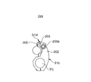
反転前倍胴39の第2の排紙側渡し胴37との対接部分よりもシート搬送方向下流側には、図2に示されるように、シートS1の他方の端部としての後端(尻側端部)を受け取って保持する第3搬送部としての反転スイング装置31bが対向して配置されている。なお、反転スイング装置31bはシートS1の表裏を反転させる反転部をも構成する。   As shown in FIG. 2, as shown in FIG. 2, the rear end (the other end portion of the sheet S <b> 1) is located downstream of the contact portion of the pre-reverse double cylinder 39 with the second discharge-side transfer cylinder 37. A reversing swing device 31b as a third transport unit that receives and holds the bottom end) is disposed to face each other. The reversing swing device 31b also constitutes a reversing unit that reverses the front and back of the sheet S1.

反転スイング装置31bは、フレーム3aに回動自在に支持された反転スイング軸31jと、この反転スイング軸31jに固定されたスイングアーム202と、当該スイングアーム202の先端に固定された爪台205とを備えている。   The reverse swing device 31b includes a reverse swing shaft 31j that is rotatably supported by the frame 3a, a swing arm 202 fixed to the reverse swing shaft 31j, and a claw base 205 fixed to the tip of the swing arm 202. It has.

また、反転スイング装置31bは、スイングアーム202の先端に回動自在に支持された回動軸203aと、当該回動軸203aに固定され爪台205と対向するスイング爪203とを備えている。スイング爪203は回動軸203aの回動により爪台205に対して開閉動作を行い、スイング爪203が閉じると当該爪台205とスイング爪203とによってシートS1を挟み付けて保持し、スイング爪203が開くと当該シートS1の保持を解放する。スイング爪203と爪台205とにより第3保持装置としてのくわえ爪装置31btが構成される。   The reverse swing device 31b includes a rotation shaft 203a that is rotatably supported at the tip of the swing arm 202, and a swing claw 203 that is fixed to the rotation shaft 203a and faces the claw base 205. The swing claw 203 opens and closes the claw base 205 by the rotation of the rotation shaft 203a. When the swing claw 203 is closed, the sheet S1 is sandwiched and held between the claw base 205 and the swing claw 203. When 203 is opened, the holding of the sheet S1 is released. The swing claw 203 and the claw base 205 constitute a holding claw device 31bt as a third holding device.

反転スイング装置31bは、印刷胴33の第1の排紙側渡し胴36との対接部分よりも印刷胴33の回転方向下流側かつ給紙側渡し胴32との対接部分よりも印刷胴33の回転方向上流側において印刷胴33に対向して配置されている。そして、この反転スイング装置31bは、反転前倍胴39により搬送されるシートS1の後端を受け取る破線で示された受取位置(図1)と、印刷胴33の印刷胴くわえ爪装置33a、33b、33cにシートS1の後端を受け渡す実線で示された受渡位置(図1)との間で揺動自在にフレーム3aに支持されている。なお、第1の排紙側渡し胴36、第2の排紙側渡し胴37、反転前倍胴39、反転スイング装置31bにより搬送されるシートS1の経路がシート反転経路を構成する。   The reversing swing device 31b is located downstream of the printing cylinder 33 in the rotational direction of the printing cylinder 33 with respect to the first discharge-side transfer cylinder 36 and more than the printing cylinder with respect to the feeding cylinder 32. It is disposed opposite to the printing cylinder 33 on the upstream side in the rotational direction of 33. The reversing swing device 31b includes a receiving position (FIG. 1) indicated by a broken line that receives the rear end of the sheet S1 conveyed by the pre-reversing double cylinder 39, and printing cylinder holding claw devices 33a and 33b of the printing cylinder 33. , 33c is supported by the frame 3a so as to be swingable between a delivery position (FIG. 1) indicated by a solid line that delivers the rear end of the sheet S1. The path of the sheet S1 conveyed by the first sheet discharge side transfer cylinder 36, the second sheet discharge side transfer cylinder 37, the pre-reverse double cylinder 39, and the reverse swing device 31b constitutes a sheet reverse path.

第2の排紙側渡し胴37のくわえ爪装置37aは、紙取胴38のくわえ爪装置38aと反転前倍胴39のくわえ爪装置39aとの間で選択的にシートS1を受け渡すことが可能に駆動される。また、紙取胴38のくわえ爪装置38aは、第2の排紙側渡し胴37により搬送されるシートS1の先端を選択的に受け取ることが可能に駆動され、これらくわえ爪装置37a、38aはシートS1の搬送先を排紙装置4または反転スイング装置31bに切替える、すなわち、シートS1の搬送経路をシート排出経路またはシート反転経路に切替える搬送経路切替手段82(図5)を構成する。   The gripping claw device 37a of the second paper discharge side transfer cylinder 37 can selectively deliver the sheet S1 between the gripping claw device 38a of the paper take-up cylinder 38 and the gripping claw device 39a of the pre-reverse double cylinder 39. Driven possible. Further, the gripping claw device 38a of the paper take-up cylinder 38 is driven so as to be able to selectively receive the leading end of the sheet S1 conveyed by the second paper discharge side transfer cylinder 37. The gripping claw devices 37a, 38a A conveyance path switching unit 82 (FIG. 5) is configured to switch the conveyance destination of the sheet S1 to the paper discharge device 4 or the reverse swing device 31b, that is, to switch the conveyance path of the sheet S1 to the sheet discharge route or the sheet reverse route.

<反転スイング装置のスイング機構>
次に、デジタル印刷ユニット3における反転スイング装置31bのスイング機構300について説明する。
<Swing mechanism of reverse swing device>
Next, the swing mechanism 300 of the reverse swing device 31b in the digital printing unit 3 will be described.

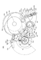
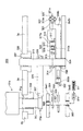
図3および図4に示すように、スイング機構300は反転スイング装置31bを揺動させる機構であり、本機のサブフレーム3as1およびサブフレーム3as2間にベアリング302、306を介してカム軸301が回転可能に軸支され、当該カム軸301にカム304およびサブカム305が固定されている。カム軸301には、本機の駆動源により回転されるギア290と差動歯車機構としてのハーモニックドライブ(登録商標)361を介して連結されたギア303が軸着されている。図3に示されるように、カム304およびサブカム305のカム面は大径部と小径部との高低差が大きく形成されている。   As shown in FIGS. 3 and 4, the swing mechanism 300 is a mechanism for swinging the reversing swing device 31b, and the camshaft 301 rotates via bearings 302 and 306 between the subframe 3as1 and the subframe 3as2 of this machine. A cam 304 and a sub cam 305 are fixed to the cam shaft 301. A gear 303 connected to a gear 290 rotated by a drive source of this machine and a harmonic drive (registered trademark) 361 as a differential gear mechanism is mounted on the camshaft 301. As shown in FIG. 3, the cam surfaces of the cam 304 and the sub cam 305 are formed with a large difference in height between the large diameter portion and the small diameter portion.

フレーム3aの側方には、サブフレーム3aS3が設けられており、レバー軸311がフレーム3aとサブフレーム3aS3との間で回動自在に支持されている。すなわち、レバー軸311の一端はサブフレーム3aS3のベアリング335を介して回動自在に支持されており、当該レバー軸311の他端はフレーム3aのベアリング保持部338に保持されるベアリング337に回転自在に支持されている。   A subframe 3aS3 is provided on the side of the frame 3a, and a lever shaft 311 is rotatably supported between the frame 3a and the subframe 3aS3. That is, one end of the lever shaft 311 is rotatably supported via the bearing 335 of the sub-frame 3aS3, and the other end of the lever shaft 311 is rotatable by the bearing 337 held by the bearing holding portion 338 of the frame 3a. It is supported by.

フレーム3aには、ベアリング保持部328に保持されているベアリング31gを介して当該反転スイング装置31bのスイング軸31jが回動自在に軸支されており、当該スイング軸31jの先端にはピニオンギア31pが固定されている。   A swing shaft 31j of the reversing swing device 31b is rotatably supported on the frame 3a via a bearing 31g held by a bearing holding portion 328, and a pinion gear 31p is provided at the tip of the swing shaft 31j. Is fixed.

レバー軸311には、第1レバー313の一端がボルト314により割締め固定されている。第1レバー313の他端にはピン317aが設けられており、このピン317aにカムフォロワ317が回動自在に支持されている。第1レバー313は、カムフォロワ317がカム軸301に軸着されたカム304と対接するように配設されている。   One end of the first lever 313 is fixed to the lever shaft 311 by bolts 314. A pin 317a is provided at the other end of the first lever 313, and a cam follower 317 is rotatably supported by the pin 317a. The first lever 313 is disposed so that the cam follower 317 is in contact with the cam 304 that is attached to the cam shaft 301.

また、レバー軸311には、第2レバー325の一端がボルト326により割締め固定されている。第2レバー325の他端には、ピニオンギア31pと噛合するセグメントギア327が固定される。図3に示されるように、セグメントギア327は大きな半径R1で形成され、ピニオンギア31pは当該セグメントギア327の半径R1よりも格段に小さい半径R2で形成されている。ここで、ピニオンギア31pとセグメントギア327とによりラック・ピニオン機構を構成する。   One end of the second lever 325 is fixed to the lever shaft 311 by bolts 326. A segment gear 327 that meshes with the pinion gear 31p is fixed to the other end of the second lever 325. As shown in FIG. 3, the segment gear 327 is formed with a large radius R1, and the pinion gear 31p is formed with a radius R2 that is much smaller than the radius R1 of the segment gear 327. Here, the pinion gear 31p and the segment gear 327 constitute a rack and pinion mechanism.

さらに、レバー軸311には、第3レバー331がベアリング336を介して回動自在に支持されている。第3レバー331の一方の端部には、ピン332aが取り付けられており、このピン332aにベアリング333を介してカムフォロワ332が回動自在に取り付けられている。第3レバー331は、カムフォロワ332がカム軸301に軸着されたサブカム305と対接するように配設されている。そして、第3レバー331の他方の端部には、両側面にそれぞれピン319a、319bが設けられたホルダ321が回動自在に支持されている。このホルダ321にはピン319a、319bの軸線と直交する方向に貫通穴321aが設けられている。   Further, a third lever 331 is rotatably supported on the lever shaft 311 via a bearing 336. A pin 332a is attached to one end of the third lever 331, and a cam follower 332 is rotatably attached to the pin 332a via a bearing 333. The third lever 331 is disposed so that the cam follower 332 is in contact with the sub cam 305 mounted on the cam shaft 301. A holder 321 provided with pins 319a and 319b on both side surfaces is rotatably supported at the other end of the third lever 331. The holder 321 is provided with a through hole 321a in a direction orthogonal to the axes of the pins 319a and 319b.

322は第1レバー313と第3レバー331とを連結する連結部材であり、当該連結部材322のヘッド部315が第1レバー313の他端に設けられたピン316に回動自在に支持されている。ヘッド部315にはネジが形成された軸部322cが設けられており、この軸部322cは第3レバー331のホルダ321の貫通穴321aに挿通されている。   Reference numeral 322 denotes a connecting member that connects the first lever 313 and the third lever 331, and the head portion 315 of the connecting member 322 is rotatably supported by a pin 316 provided at the other end of the first lever 313. Yes. The head portion 315 is provided with a shaft portion 322 c formed with a screw. The shaft portion 322 c is inserted into the through hole 321 a of the holder 321 of the third lever 331.

ナット316aが軸部322cのネジに螺合され、軸部322cに挿通され当該軸部322cに対して移動自在に支持されたばね受け部材322bがナット316aと第3レバー331のホルダ321との間に配設されている。ばね受け部材322bとナット316との間には付勢手段としてのばね322aが介装され、第1レバー313の他端と第3レバー331の他方の端部とを互いに離反させる方向に付勢している。このばね322aにより、第1レバー313のカムフォロワ317をカム304に押圧すると共に、第3レバー331のカムフォロワ332をサブカム305に押圧している。なお、ナット316aはばね322aのばね力を調整する付勢力調整手段として機能する。   A nut 316a is screwed into a screw of the shaft portion 322c, and a spring receiving member 322b inserted through the shaft portion 322c and supported movably with respect to the shaft portion 322c is interposed between the nut 316a and the holder 321 of the third lever 331. It is arranged. A spring 322a as an urging means is interposed between the spring receiving member 322b and the nut 316, and the other end of the first lever 313 and the other end of the third lever 331 are urged away from each other. doing. The spring 322 a presses the cam follower 317 of the first lever 313 against the cam 304 and also presses the cam follower 332 of the third lever 331 against the sub cam 305. The nut 316a functions as an urging force adjusting means for adjusting the spring force of the spring 322a.

カム304およびサブカム305は、第1レバー313と第3レバー331との相対的な位置関係がほとんど変わらないようにそれぞれのカム面の形状が形成されている。すなわち、図3に示されるように、第1レバー313のカムフォロワ317がカム304の小径部と対接しているときには、第3レバー331のカムフォロワ332がサブカム305の大径部と対接しており、第1レバー313のカムフォロワ317がカム304の大径部と対接しているときには、第3レバー331のカムフォロワ332がサブカム305の小径部と対接するようになっている。   The cam 304 and the sub cam 305 are formed with respective cam surfaces so that the relative positional relationship between the first lever 313 and the third lever 331 hardly changes. That is, as shown in FIG. 3, when the cam follower 317 of the first lever 313 is in contact with the small diameter portion of the cam 304, the cam follower 332 of the third lever 331 is in contact with the large diameter portion of the sub cam 305, When the cam follower 317 of the first lever 313 is in contact with the large diameter portion of the cam 304, the cam follower 332 of the third lever 331 is in contact with the small diameter portion of the sub cam 305.

ここで、カム304およびサブカム305、カムフォロワ317を備えた第1レバー313およびカムフォロワ332を備えた第3レバー331、付勢手段としてのばね322aを備えた連結部材322により共役カム(確動カム)を構成する。   Here, the cam 304, the sub cam 305, the first lever 313 provided with the cam follower 317, the third lever 331 provided with the cam follower 332, and the connecting member 322 provided with the spring 322a as the urging means are conjugated cams (positive cams). Configure.

かかる構成に加えてスイング機構300は、本機の駆動源の駆動を反転スイング装置31bに伝達する反転スイング駆動系には、反転スイング装置31bの揺動速度を調整する調整部を備えている。この調整部は、本機の駆動源により駆動されるギア290とカム軸301に軸着されたギア303との間に設けられたハーモニックドライブ(登録商標)361と調整モータ363とを備えている。   In addition to this configuration, the swing mechanism 300 includes an adjustment unit that adjusts the swing speed of the reversing swing device 31b in the reversing swing drive system that transmits the drive of the drive source of the present apparatus to the reversing swing device 31b. This adjustment unit includes a harmonic drive (registered trademark) 361 and an adjustment motor 363 provided between a gear 290 driven by a drive source of this machine and a gear 303 attached to the camshaft 301. .

ハーモニックドライブ361は、ウェーブ・ジェネレータと呼ばれる入力軸、サーキュラ・スプラインと呼ばれる出力軸、フレクスプラインと呼ばれる制御軸の3軸を備え、入力軸がギア290に駆動連結され、出力軸がギア303に駆動連結され、制御軸が調整モータ363に駆動連結されている。ハーモニックドライブ361は、制御軸を停止させているときには出力軸が入力軸と同速で回転し、制御軸の速度を変えることにより出力軸が入力軸の回転速度に対し速度差をもって回転する公知の減速機構であり、制御軸の速度、すなわち調整モータ363の回転速度に応じて減速比を調整することができるものである。   The harmonic drive 361 includes an input shaft called a wave generator, an output shaft called a circular spline, and a control shaft called a flex spline. The input shaft is drivingly connected to the gear 290, and the output shaft is driven to the gear 303. The control shaft is connected to the adjustment motor 363 by driving. In the harmonic drive 361, when the control shaft is stopped, the output shaft rotates at the same speed as the input shaft, and the output shaft rotates with a speed difference with respect to the rotational speed of the input shaft by changing the speed of the control shaft. This is a reduction mechanism that can adjust the reduction ratio according to the speed of the control shaft, that is, the rotation speed of the adjustment motor 363.

<デジタル印刷装置の制御系の構成>
図3に示すように、デジタル印刷装置1は、全体を統括制御するCPU(Central processing Unit)構成でなる制御部としての制御装置81を備えている。制御装置81には、シートS1の片面だけにデジタル印刷処理を施す片面印刷モード、シートS1の表面および裏面の両面にデジタル印刷処理を施す両面印刷モードの何れかを作業者に選択させる印刷モード選択スイッチ80、給紙部2の連続供給バルブ26および間欠供給バルブ27、インクジェットノズル部34の各インクジェットノズルヘッド34a〜34d、搬送経路切替手段82、調整モータ363、駆動モータ383、シートサイズ検知部93、および印刷胴33の位相を検出する位相検出部としてのロータリエンコーダでなる位相検出センサ94が接続されている。ここで、シートサイズ検知部93は、作業者によりシートS1の搬送方向長さが入力されるシートサイズ入力装置や、自動的にシートS1の搬送方向長さを検出するシートサイズ検出器のことをいう。
<Configuration of control system of digital printing device>
As shown in FIG. 3, the digital printing apparatus 1 includes a control device 81 as a control unit having a CPU (Central processing Unit) configuration for overall control. The control device 81 allows the operator to select either a single-sided printing mode in which digital printing processing is performed on only one side of the sheet S1, or a double-sided printing mode in which digital printing processing is performed on both the front and back surfaces of the sheet S1. The switch 80, the continuous supply valve 26 and the intermittent supply valve 27 of the paper feed unit 2, the inkjet nozzle heads 34a to 34d of the inkjet nozzle unit 34, the conveyance path switching means 82, the adjustment motor 363, the drive motor 383, and the sheet size detection unit 93. , And a phase detection sensor 94 composed of a rotary encoder as a phase detection unit for detecting the phase of the printing cylinder 33 is connected. Here, the sheet size detection unit 93 is a sheet size input device in which the length of the sheet S1 in the conveyance direction is input by an operator, or a sheet size detector that automatically detects the length of the sheet S1 in the conveyance direction. Say.

<デジタル印刷装置の印刷動作>
このように構成されたデジタル印刷装置1の印刷動作について、片面印刷モードが選択された場合と、両面印刷モードが選択された場合に分けて説明する。
<Printing operation of digital printing device>
The printing operation of the digital printing apparatus 1 configured as described above will be described separately when the single-sided printing mode is selected and when the double-sided printing mode is selected.

図1に示されるように、作業者の印刷モード選択スイッチ80の操作により片面印刷モードが選択されると、制御装置81は連続供給バルブ26を作動させ、これにより第1吸23aおよび第2吸23bが積載台21のシートS1を吸着しフィーダボードFBへ搬送する。   As shown in FIG. 1, when the single-sided printing mode is selected by the operator's operation of the printing mode selection switch 80, the control device 81 activates the continuous supply valve 26, whereby the first suction 23a and the second suction are performed. 23b adsorbs the sheet S1 on the loading table 21 and conveys it to the feeder board FB.

連続供給バルブ26は、印刷胴33の1回転中に当該印刷胴33に設けられた印刷胴くわえ爪装置33a、33b、33cの数と同じ枚数のシートS1を供給するタイミング、換言すると、印刷胴33における各くわえ爪装置33a、33b、33cと給紙側渡し胴32のくわえ爪装置32aとが対向するタイミング(第1の周期)ごとに連続供給バルブ26が「開」して第1吸23aおよび第2吸23bの負圧源25からの吸引が行なわれるように制御装置81により制御される。このように、印刷胴33の全ての印刷胴くわえ爪装置33a、33b、33cがシートS1をくわえるように当該シートS1を供給することを連続給紙と呼び、連続給紙における連続供給バルブ26の開閉周期を第1の周期と呼ぶ。これにより、サッカー装置23はシートS1を第1の周期でフィーダボードFBへ搬送する。   The continuous supply valve 26 feeds the same number of sheets S1 as the number of the printing cylinder holding nail devices 33a, 33b, 33c provided in the printing cylinder 33 during one rotation of the printing cylinder 33, in other words, the printing cylinder. The continuous supply valve 26 is “opened” at each timing (first period) at which the gripping claw devices 33a, 33b, 33c of the feed 33 and the gripping claw device 32a of the sheet feeding side transfer cylinder 32 face each other. The controller 81 controls the suction of the second suction 23b from the negative pressure source 25. In this way, supplying the sheet S1 so that all the printing cylinder holding claw devices 33a, 33b, and 33c of the printing cylinder 33 hold the sheet S1 is called continuous feeding, and the continuous supply valve 26 in continuous feeding is used. The opening / closing cycle is referred to as a first cycle. Thereby, the soccer device 23 conveys the sheet S1 to the feeder board FB in the first cycle.

フィーダボードFBにより搬送されるシートS1はその先端がスイング装置31fのくわえ爪装置によって保持された後に当該スイング装置31fの揺動により給紙側渡し胴32へ向かって搬送され、その給紙側渡し胴32のくわえ爪装置32aに当該シートS1の先端がくわえ替えされる。   After the leading end of the sheet S1 conveyed by the feeder board FB is held by the gripping claw device of the swing device 31f, the sheet S1 is conveyed toward the paper supply side transfer cylinder 32 by the swing of the swing device 31f, and the paper supply side transfer is performed. The leading end of the sheet S1 is replaced by the holding claw device 32a of the trunk 32.

給紙側渡し胴32の回転に伴って搬送されるシートS1は、印刷胴33との対接部分において給紙側渡し胴32のくわえ爪装置32aから印刷胴33の印刷胴くわえ爪装置33a〜33cの何れかにその先端がくわえ替えされた後、印刷胴33の回転とともに搬送される。このときシートS1の全面は、印刷胴33における複数の吸引孔を介して当該印刷胴33の支持面33d〜33fに吸着されて当該支持面33d〜33fに密着する。   The sheet S1 conveyed along with the rotation of the sheet feeding side transfer cylinder 32 is transferred from the gripping claw device 32a of the sheet feeding side transfer cylinder 32 to the printing cylinder holding claw device 33a to 33a of the printing cylinder 33 at the contact portion with the printing cylinder 33. After the tip is replaced by any of 33c, it is conveyed along with the rotation of the printing cylinder 33. At this time, the entire surface of the sheet S1 is adsorbed to the support surfaces 33d to 33f of the printing cylinder 33 through the plurality of suction holes in the printing cylinder 33 and is in close contact with the support surfaces 33d to 33f.

印刷胴33により搬送されるシートS1の表面には、インクジェットノズル部34のインクジェットノズルヘッド34a〜34dから微滴化されたインクが吐出されることによりデジタル印刷処理が施される。シートS1は印刷胴33の支持面33d〜33eに密着しているため、インクジェットノズルヘッド34a〜34dとの間の微小間隔が維持された状態で搬送される。この微小間隔が維持されることにより吐出されたインクをシートS1に高精度で着弾させることができ、高品質な印刷を行うことができる。   Digital printing processing is performed on the surface of the sheet S <b> 1 conveyed by the printing cylinder 33 by ejecting fine droplets of ink from the inkjet nozzle heads 34 a to 34 d of the inkjet nozzle portion 34. Since the sheet S1 is in close contact with the support surfaces 33d to 33e of the printing cylinder 33, the sheet S1 is conveyed in a state in which a minute distance between the inkjet nozzle heads 34a to 34d is maintained. By maintaining this minute interval, the ejected ink can be landed on the sheet S1 with high accuracy, and high-quality printing can be performed.

インクジェットノズル部34による印刷が行われたシートS1は、印刷胴33とインキ乾燥ランプ35との間を通過し、当該インキ乾燥ランプ35からの光が照射され、これによりシートS1のインキが乾燥する。その後シートS1は第1の排紙側渡し胴36へ搬送される。   The sheet S1 that has been printed by the inkjet nozzle unit 34 passes between the printing cylinder 33 and the ink drying lamp 35, and is irradiated with light from the ink drying lamp 35, whereby the ink on the sheet S1 is dried. . Thereafter, the sheet S1 is conveyed to the first paper discharge side transfer cylinder 36.

シートS1は、印刷胴33の支持面33d、33e、33fに密着されているため、インキ乾燥ランプ35からシートS1の全面に均一に光が照射され、むらの無いインキ乾燥が行なわれる。   Since the sheet S1 is in close contact with the support surfaces 33d, 33e, and 33f of the printing cylinder 33, the entire surface of the sheet S1 is uniformly irradiated with light from the ink drying lamp 35, and the ink is dried without unevenness.

図6に示すように、印刷胴33と第1の排紙側渡し胴36との対接部分において印刷胴33の印刷胴くわえ爪装置33a〜33cから第1の排紙側渡し胴36のくわえ爪装置36aにシートS1の先端がくわえ替えされる。その後、図7に示すように、第1の排紙側渡し胴36のくわえ爪装置36aに保持されたシートS1は、第1の排紙側渡し胴36と第2の排紙側渡し胴37との対接部分において、第1の排紙側渡し胴36のくわえ爪装置36aから第2の排紙側渡し胴37のくわえ爪装置37aにその先端がくわえ替えされる。   As shown in FIG. 6, in the contact portion between the printing cylinder 33 and the first paper discharge side transfer cylinder 36, the print cylinder holding nail devices 33 a to 33 c of the printing cylinder 33 hold the first paper discharge side transfer cylinder 36. The leading end of the sheet S1 is replaced with the nail device 36a. Thereafter, as shown in FIG. 7, the sheet S <b> 1 held by the gripping claw device 36 a of the first paper discharge side transfer drum 36 is transferred to the first paper discharge side transfer drum 36 and the second paper discharge side transfer drum 37. At the contact portion, the gripper claw device 36a of the first paper discharge side transfer drum 36 is replaced with the gripper claw device 37a of the second paper discharge side transfer drum 37.

片面印刷モードの場合、制御装置81は、全てのシートS1が第2の排紙側渡胴37から紙取胴38へ受け渡されるように搬送経路切替手段82を制御する。すなわち、シートS1の先端が第2の排紙側渡し胴37と紙取胴38との対接部分に位置付けられる位相において、第2の排紙側渡し胴37のくわえ爪装置37aがシートS1の先端の保持を解除するとともに、紙取胴38のくわえ爪装置38aがシートS1の先端をくわえて保持する。これにより片面に印刷が施されたシートS1は第2の排紙側渡し胴37から紙取胴38へくわえ替えされて搬送される。   In the single-sided printing mode, the control device 81 controls the transport path switching unit 82 so that all the sheets S1 are transferred from the second paper discharge side transfer cylinder 37 to the paper take-up cylinder 38. That is, in a phase where the leading end of the sheet S1 is positioned at the contact portion between the second discharge side transfer cylinder 37 and the paper take-up cylinder 38, the gripping claw device 37a of the second discharge side transfer cylinder 37 moves the sheet S1. The holding of the leading edge is released, and the gripping claw device 38a of the paper drum 38 holds and holds the leading edge of the sheet S1. Thus, the sheet S1 printed on one side is transferred from the second discharge side transfer cylinder 37 to the paper take-up cylinder 38 and conveyed.

紙取胴38のくわえ爪装置38aにくわえ替えされたシートS1は、デリバリーベルト40の上方に紙取胴38のくわえ爪装置38aが位置したタイミングで当該くわえ爪装置38aによる保持が解除され、デリバリーベルト40上に載せられる。   The sheet S1 that has been replaced by the gripper device 38a of the paper drum 38 is released from being held by the gripper device 38a at the timing when the gripper device 38a of the paper drum 38 is positioned above the delivery belt 40, and delivered. It is placed on the belt 40.

デリバリーベルト40上に載せられたシートS1は当該デリバリーベルト40の走行とともに搬送され、表面にデジタル印刷処理の施されたシートS1が排紙装置4の積載台41上に排出される。   The sheet S1 placed on the delivery belt 40 is conveyed along with the travel of the delivery belt 40, and the sheet S1 subjected to digital printing processing on the surface is discharged onto the stacking table 41 of the paper discharge device 4.

一方、作業者の印刷モード選択スイッチ80の操作により両面印刷モードが選択された場合、制御装置81(図5)は反転前倍胴39が他の胴と同期して回転するよう駆動モータ383を駆動させる。この状態で制御装置81は間欠供給バルブ27を作動させ、これにより、第1吸23aおよび第2吸23bがり積載台21のシートS1を吸着しフィーダボードFBへ搬送する。   On the other hand, when the duplex printing mode is selected by the operator's operation of the printing mode selection switch 80, the control device 81 (FIG. 5) controls the drive motor 383 so that the pre-reverse double cylinder 39 rotates in synchronization with the other cylinders. Drive. In this state, the control device 81 operates the intermittent supply valve 27, thereby sucking the sheet S1 of the first suction 23a and the second suction 23b and placing it on the feeder board FB.

間欠供給バルブ27は、連続供給のタイミングに対して1枚おきのタイミングでシートS1を供給するタイミング(第1の周期の2倍の周期となる第2の周期)、換言すると、印刷胴33における各くわえ爪装置33a、33b、33cと給紙側渡し胴32のくわえ爪装置32aとが対向するタイミングで、バルブが「開」、「閉」、「開」、「閉」、…、となるように制御装置81により制御される。これは、連続給紙の周期の2倍の周期である。このように、印刷胴33の印刷胴くわえ爪装置33a、33b、33cが一つおきにシートS1をくわえるように当該シートS1を供給することを間欠給紙と呼び、間欠給紙における間欠供給バルブ27の開閉周期を第2の周期と呼ぶ。これにより、サッカー装置23はシートS1を第2の周期で1枚おきに間欠的に吸着しフィーダボードFBへ搬送する。   The intermittent supply valve 27 supplies the sheet S1 at every other sheet timing with respect to the continuous supply timing (second period that is twice as long as the first period), in other words, in the printing cylinder 33. At the timing when each gripper device 33a, 33b, 33c and the gripper device 32a of the feed-side transfer cylinder 32 face each other, the valves become “open”, “closed”, “open”, “closed”,. Control is performed by the control device 81 as described above. This is twice as long as the continuous feeding cycle. In this way, feeding the sheet S1 so that the printing cylinder holding claw devices 33a, 33b, 33c of the printing cylinder 33 hold the sheet S1 every other time is called intermittent feeding, and the intermittent supply valve in intermittent feeding The open / close cycle of 27 is referred to as a second cycle. Accordingly, the soccer device 23 intermittently sucks every other sheet S1 in the second period and conveys it to the feeder board FB.

サッカー装置23によりフィーダボードFBへ送り出されたシートS1は、片面印刷モードの場合と同様にスイング装置31fおよび給紙側渡し胴32を介して印刷胴33に受け渡されるが、シートS1は間欠給紙のタイミングで送り出されているため、印刷胴33の印刷胴くわえ爪装置33a〜33cは一つおきに給紙側渡し胴32から搬送される新規なシートS1を受取る。   The sheet S1 sent to the feeder board FB by the soccer device 23 is delivered to the printing cylinder 33 via the swing device 31f and the sheet feeding side transfer cylinder 32 as in the single-sided printing mode, but the sheet S1 is intermittently fed. Since the paper is fed at the paper timing, the printing cylinder holding claw devices 33a to 33c of the printing cylinder 33 receive every other new sheet S1 conveyed from the sheet feeding side transfer cylinder 32.

その後、シートS1はインクジェットノズル部34に搬送され、その一方の面(表面)に表面用の印刷が施される。ここで、制御装置81は、位相検出センサ94からの検出信号に基づいて、印刷胴33の印刷胴くわえ爪装置33a〜33cの一つおきに保持された新規なシートS1に対して印刷を施し、シートS1を保持していない印刷胴くわえ爪装置33a〜33cの支持面33d〜33fに対して印刷を行なわないようにインクジェットノズル部34の各インクジェットノズルヘッド34a〜34dを制御する。   Thereafter, the sheet S1 is conveyed to the inkjet nozzle portion 34, and printing for the surface is performed on one surface (front surface) thereof. Here, based on the detection signal from the phase detection sensor 94, the control device 81 performs printing on a new sheet S1 held every other one of the printing cylinder holding nail devices 33a to 33c of the printing cylinder 33. The inkjet nozzle heads 34a to 34d of the inkjet nozzle portion 34 are controlled so that printing is not performed on the support surfaces 33d to 33f of the printing cylinder holding claw devices 33a to 33c that do not hold the sheet S1.

両面印刷モードの場合には、制御装置81は、インクジェットノズル部34により表面に印刷が施されたシートS1が、第2の排紙側渡し胴37から紙取胴38へ受け渡されずに、反転前倍胴39に受け渡されるように、搬送経路切替手段82を制御する。   In the double-sided printing mode, the control device 81 does not transfer the sheet S1 printed on the surface by the ink jet nozzle unit 34 from the second paper discharge side transfer cylinder 37 to the paper cylinder 38, The conveyance path switching means 82 is controlled so as to be delivered to the pre-reverse double cylinder 39.

すなわち、両面印刷モードの場合においては、表面に印刷が施されているが他方の面(裏面)にはデジタル印刷処理されていないシートS1が第2の排紙側渡し胴37と紙取胴38との対接部分に位置付けられる位相において、第2の排紙側渡し胴37のくわえ爪装置37aの爪は開かずに閉じたままの状態、すなわちシートS1の先端を保持した状態が維持されるとともに、紙取胴38のくわえ爪装置38aの爪は閉じずに開いた状態が維持される。   That is, in the case of the duplex printing mode, the sheet S1 that has been printed on the front surface but not digitally printed on the other surface (back surface) is the second discharge side transfer drum 37 and the paper drum 38. In the phase positioned at the contact portion, the claw of the gripping claw device 37a of the second paper discharge side transfer cylinder 37 is kept open, that is, the state in which the leading edge of the sheet S1 is held is maintained. At the same time, the claw of the gripping claw device 38a of the paper drum 38 is kept open without being closed.

これにより表面のみに印刷が施されたシートS1は第2の排紙側渡し胴37から紙取胴38へくわえ替えされることなく反転前倍胴39へ搬送される。すなわち、第2の排紙側渡し胴37と反転前倍胴39との対接部分において反転前倍胴39くわえ爪装置39aの爪を閉じてシートS1の先端を保持させるとともに、第2の排紙側渡し胴37のくわえ爪装置37aの爪を開いてシートS1の先端の保持を解除し、図8に示すように、第2の排紙側渡し胴37のくわえ爪装置37aから反転前倍胴39のくわえ爪装置39aにシートS1の先端をくわえ替えさせる。   As a result, the sheet S1 printed only on the front surface is conveyed from the second paper discharge side transfer cylinder 37 to the paper take-up cylinder 38 without being replaced by the pre-inversion double cylinder 39. That is, the nail of the pre-reverse double cylinder 39 gripping claw device 39a is closed at the contact portion between the second discharge side transfer cylinder 37 and the pre-reverse double cylinder 39 to hold the leading edge of the sheet S1, and the second discharge The nail of the gripping claw device 37a of the paper-side transfer cylinder 37 is opened to release the holding of the leading edge of the sheet S1, and as shown in FIG. The holding claw device 39a of the trunk 39 holds the leading end of the sheet S1.

図9に示すように、反転前倍胴39の回転とともに搬送されるシートS1は、反転スイング装置31bが実線で示される受渡位置から破線で示される受取位置に揺動し、シートS1の後端(紙尻側端部)を当該反転スイング装置31bの反転くわえ爪装置31btにより保持すると同時に、反転前倍胴39のくわえ爪装置39aによるシートS1の先端に対する保持を解除する。これにより、反転前倍胴39から反転スイング装置31bにシートS1の後端がくわえ替えされる。   As shown in FIG. 9, the sheet S1 conveyed along with the rotation of the pre-reversing double cylinder 39 swings the reverse swing device 31b from the delivery position indicated by the solid line to the reception position indicated by the broken line, and the rear end of the sheet S1. At the same time as holding the (paper end side end) by the reverse gripping claw device 31bt of the reversing swing device 31b, the holding of the pre-reverse double cylinder 39 by the gripping claw device 39a with respect to the leading edge of the sheet S1 is released. As a result, the rear end of the sheet S1 is replaced from the pre-reverse double cylinder 39 to the reverse swing device 31b.

その後、図9に示すように、反転スイング装置31bは破線で示す受取位置から実線で示す受渡位置へ揺動し、これによりシートS1はその後端を先頭にして印刷胴33に向けて搬送され、反転スイング装置31bのくわえ爪装置31btから印刷胴33の印刷胴くわえ爪装置33a〜33cの何れかにシートS1の後端がくわえ替えされる。   Thereafter, as shown in FIG. 9, the reverse swing device 31b swings from the receiving position indicated by the broken line to the delivery position indicated by the solid line, whereby the sheet S1 is conveyed toward the printing cylinder 33 with the trailing edge at the top, The rear end of the sheet S1 is replaced by any of the gripper claw devices 33a to 33c of the printing cylinder 33 from the gripper claw device 31bt of the reverse swing device 31b.

図3に示されるように、反転スイング装置31bの受取位置と受渡位置との間の揺動角(振れ角)θ2は大きく、この大きな振れ角θ2を得るために本実施の形態では共役カムとラック・ピニオン機構を組合せたスイング機構300が用いられている。すなわち、図3および図4に示されたように、スイング機構300では、本機の駆動源により回転されるギア290およびハーモニックドライブ361を介してギア303が回転されると、カム軸301を介してカム304及びサブカム305が回転する。   As shown in FIG. 3, the swing angle (swing angle) θ2 between the receiving position and the delivery position of the reversing swing device 31b is large. In order to obtain this large swing angle θ2, in this embodiment, a conjugate cam and A swing mechanism 300 combined with a rack and pinion mechanism is used. That is, as shown in FIG. 3 and FIG. 4, in the swing mechanism 300, when the gear 303 is rotated via the gear 290 and the harmonic drive 361 that are rotated by the drive source of this machine, As a result, the cam 304 and the sub cam 305 rotate.

カム304のカム面には第1レバー313のカムフォロワ317が当接されると同時に、サブカム305のカム面には第3レバー331のカムフォロワ332が当接されているので、カム304の回転により、第1レバー313はカムフォロワ317を介してカム304のカム面の形状にしたがって揺動する。第1レバー313の揺動によりレバー軸311が回動し、当該レバー軸311に固定されている第2レバー325がセグメントギア327を伴って揺動角(振れ角)θ1で揺動する。   The cam follower 317 of the first lever 313 is in contact with the cam surface of the cam 304, and at the same time, the cam follower 332 of the third lever 331 is in contact with the cam surface of the sub cam 305. The first lever 313 swings according to the shape of the cam surface of the cam 304 via the cam follower 317. The lever shaft 311 is rotated by the swing of the first lever 313, and the second lever 325 fixed to the lever shaft 311 swings at the swing angle (swing angle) θ <b> 1 with the segment gear 327.

第1レバー313が揺動している間、第3レバー331はカムフォロワ332を介してサブカム305のカム面の形状にしたがって揺動する。第1レバー313のカムフォロワ317および第3レバー331のカムフォロワ332はばね322aによりカム304およびサブカム305のカム面に押圧されている。すなわち、ばね322aによりばね受け部材322bが第3レバー331のホルダ321を押圧し、当該第3レバー331をカムフォロワ332がサブカム305のカム面を押圧する方向に付勢し、さらに、ばね322aによりナット316aが螺合した連結部材322を介して第1レバー313をカムフォロワ317がカム304のカム面を押圧する方向に付勢するのである。   While the first lever 313 is swinging, the third lever 331 swings according to the shape of the cam surface of the sub cam 305 via the cam follower 332. The cam follower 317 of the first lever 313 and the cam follower 332 of the third lever 331 are pressed against the cam surfaces of the cam 304 and the sub cam 305 by a spring 322a. That is, the spring receiving member 322b presses the holder 321 of the third lever 331 by the spring 322a, the third lever 331 is urged in the direction in which the cam follower 332 presses the cam surface of the sub cam 305, and the nut is further pressed by the spring 322a. The first lever 313 is biased in a direction in which the cam follower 317 presses the cam surface of the cam 304 through the connecting member 322 in which the screw 316a is screwed.

このとき、カム304およびサブカム305により、第1レバー313と第3レバー331との相対的な位置関係がほとんど変わらないため、ばね322aによる付勢力をほぼ一定とすることができ、高低差の大きいカム304およびサブカム305のカム面に対する第1レバー313のカムフォロワ317および第3レバー331のカムフォロワ332の押圧力を常に一定に保つことができる。したがって、カム飛びを起こすことなくセグメントギア327を大きな揺動角(振れ角)θ1で確実に揺動させることができるのである。   At this time, since the relative positional relationship between the first lever 313 and the third lever 331 is hardly changed by the cam 304 and the sub cam 305, the biasing force by the spring 322a can be made almost constant, and the height difference is large. The pressing force of the cam follower 317 of the first lever 313 and the cam follower 332 of the third lever 331 with respect to the cam surfaces of the cam 304 and the sub cam 305 can always be kept constant. Therefore, the segment gear 327 can be reliably swung at a large swing angle (swing angle) θ1 without causing cam jump.

第2レバー325のセグメントギア327が揺動角(振れ角)θ1で揺動すると、ピニオンギア31pを介してスイング軸31jが回動し、これにより反転スイング装置31bが揺動する。   When the segment gear 327 of the second lever 325 swings at a swing angle (swing angle) θ1, the swing shaft 31j rotates via the pinion gear 31p, and thereby the reverse swing device 31b swings.

この場合、反転スイング装置31bは、大きな半径R1で形成された第2レバー325のセグメントギア327が、その第2レバー325の回転半径R1よりも格段に小さな半径R2のピニオンギア31pと噛合されているので、第2レバー325の揺動角(振れ角)θ1を例えば4倍に拡大した一段と大きな揺動角(振れ角)θ2でくわえ爪装置31btを揺動させることができる。   In this case, in the reverse swing device 31b, the segment gear 327 of the second lever 325 formed with a large radius R1 is meshed with the pinion gear 31p with a radius R2 that is much smaller than the rotation radius R1 of the second lever 325. Therefore, the gripper device 31bt can be swung with a swing angle (swing angle) θ2 that is larger than, for example, four times the swing angle (swing angle) θ1 of the second lever 325.

これにより、反転前倍胴39と印刷胴33との間隔が広く、すなわち反転前倍胴39から印刷胴33までの距離が長い場合であっても、スイング機構300の共役カムにより大きな高低差のカム304を使用してカム飛びすることなく第2レバー325のセグメントギア327の大きな揺動角(振れ角)θ1を得ることができ、さらに、大きな半径R1の第2レバー325のセグメントギア327と小さな半径R2のピニオンギア31pとの組合せによるラック・ピニオン機構により、セグメントギア327の大きな揺動角(振れ角)θ1をさらに大きな揺動角(振れ角)θ2に変換することができるので、当該くわえ爪装置31btによるシートS1の搬送距離が伸び、かくして、反転前倍胴39から反転スイング装置31bを介してシートS1の後端を印刷胴33へ受け渡すことができる。   Thereby, even when the distance between the pre-reversal double cylinder 39 and the printing cylinder 33 is wide, that is, when the distance from the pre-reverse double cylinder 39 to the print cylinder 33 is long, a large difference in height is caused by the conjugate cam of the swing mechanism 300. A large swing angle (swing angle) θ1 of the segment gear 327 of the second lever 325 can be obtained without using the cam 304, and further, the segment gear 327 of the second lever 325 having a large radius R1 can be obtained. Since the rack and pinion mechanism in combination with the pinion gear 31p having a small radius R2 can convert the large swing angle (swing angle) θ1 of the segment gear 327 into a larger swing angle (swing angle) θ2. The conveying distance of the sheet S1 by the gripper device 31bt is increased, and thus the sheet is transferred from the pre-reverse double cylinder 39 via the reverse swing device 31b. It can be passed first to the rear end to the printing cylinder 33.

ここで、印刷胴33の印刷胴くわえ爪装置33a〜33cは給紙側渡し胴32から搬送される新規なシートS1を一つおきに保持しているのであるが、反転スイング装置31bは新規なシートS1を保持していない印刷胴くわえ爪装置33a〜33cと対向するタイミングで受渡位置へ位置付けられ、反転スイング装置31bのくわえ爪装置31btからシートS1の後端を印刷胴くわえ爪装置33a〜33cへ受け渡す。これにより、印刷胴33の印刷胴くわえ爪装置33a〜33cには、給紙側渡し胴32から受け渡された新規なシートS1と反転スイング装置31bのくわえ爪装置31btから受け渡されたシートS1とが交互に保持され、インクジェットノズル部34へ搬送される。   Here, the printing cylinder holding claw devices 33a to 33c of the printing cylinder 33 hold every other new sheet S1 conveyed from the sheet feeding side transfer cylinder 32, but the reverse swing device 31b is a new one. Positioned at the delivery position at a timing facing the printing cylinder holding claw devices 33a to 33c not holding the sheet S1, and the rear end of the sheet S1 from the holding claw device 31bt of the reverse swing device 31b is printed to the printing cylinder holding claw devices 33a to 33c. Hand over to. As a result, the new sheet S1 delivered from the feed-side transfer cylinder 32 and the sheet S1 delivered from the gripping-nail apparatus 31bt of the reverse swing device 31b to the printing cylinder holding claw devices 33a to 33c of the printing cylinder 33. Are alternately held and conveyed to the inkjet nozzle section 34.

このとき反転スイング装置31bのくわえ爪装置31btから受け渡されたシートS1は、インクジェットノズル部34により既にデジタル印刷処理の施された表面(デジタル印刷処理済みの面)が印刷胴33の支持面33d、33e、33fと対接し、シートS1の裏面(デジタル印刷未処理の面)が露出した状態で、シートS1の後端が印刷胴33の印刷胴くわえ爪装置33a〜33cにより保持された状態のまま搬送され、すなわちシートS1が表裏反転して搬送されインクジェットノズル部34によりシートS1の裏面にデジタル印刷処理が施される。   At this time, the sheet S1 delivered from the gripping claw device 31bt of the reversing swing device 31b has a surface that has already been subjected to digital printing processing by the inkjet nozzle portion 34 (surface that has been subjected to digital printing processing) 33d support surface 33d of the printing cylinder 33. , 33e, 33f in a state where the back surface of the sheet S1 (the surface not yet processed by digital printing) is exposed, and the rear end of the sheet S1 is held by the printing cylinder holding nail devices 33a to 33c of the printing cylinder 33. In other words, the sheet S <b> 1 is reversed and conveyed, and the inkjet nozzle unit 34 performs digital printing on the back surface of the sheet S <b> 1.

ここで、反転スイング装置31bのくわえ爪装置31btから受け渡された表裏反転状態のシートS1に対しては裏面用の印刷が施され、印刷胴33のくわえ爪装置33a〜33cのひとつおきに保持された新規なシートS1に対しては表面用の印刷が施されるようにインクジェットノズル部34の各インクジェットノズルヘッド34a〜34dが制御される。これにより、インクジェットノズルヘッド34a〜34dは、印刷胴33に交互に保持された新規なシートS1と表裏反転状態のシートS1に対応して表面用の印刷と裏面用の印刷を交互に行うことになる。   Here, the reverse side sheet S1 delivered from the gripping claw device 31bt of the reversing swing device 31b is printed on the back side and held every other gripping claw devices 33a to 33c of the printing cylinder 33. Each inkjet nozzle head 34a-34d of the inkjet nozzle part 34 is controlled so that printing for the surface is performed on the new sheet S1. As a result, the inkjet nozzle heads 34a to 34d alternately perform printing for the front surface and printing for the back surface corresponding to the new sheet S1 held alternately on the printing cylinder 33 and the sheet S1 in the reverse state. Become.

その後、裏面に裏面用の印刷が施されたシートS1は、片面印刷モードの場合と同様に、第1の排出側渡し胴36、第2の排紙側渡し胴37、紙取胴38を順次介してデリバリーベルト40から排紙装置4の積載台41へ排出される。   Thereafter, the sheet S1 printed on the back side is printed on the first discharge side transfer drum 36, the second discharge side transfer drum 37, and the paper drum 38 in the same manner as in the single-sided printing mode. Then, the paper is discharged from the delivery belt 40 to the loading table 41 of the paper discharge device 4.

次に、スイング機構300に設けられたハーモニックドライブ361の作用について説明する。作業者が印刷モード選択スイッチ80を介して両面印刷モードを選択すると、制御装置81は、例えば作業者によりシートサイズ検知部93に入力されたシートS1の搬送方向長さに基づき調整モータ363の回転速度を算出する。   Next, the operation of the harmonic drive 361 provided in the swing mechanism 300 will be described. When the operator selects the duplex printing mode via the printing mode selection switch 80, the control device 81 rotates the adjustment motor 363 based on, for example, the conveyance direction length of the sheet S1 input to the sheet size detection unit 93 by the operator. Calculate the speed.

制御装置81が、シートサイズ検知部93からシートS1の搬送方向長さに基づいて算出された回転速度となるよう調整モータ363を駆動すると、カム304およびサブカム305の回転速度が増速または減速される。   When the control device 81 drives the adjustment motor 363 so that the rotation speed calculated based on the conveyance direction length of the sheet S1 from the sheet size detection unit 93, the rotation speeds of the cam 304 and the sub cam 305 are increased or decreased. The

その結果、カム304により第1レバー313のスイング速度ひいては第2レバー325のスイング速度が増速又は減速するので、第2レバー325を介して反転スイング装置31bのくわえ爪装置31btを高速でスイング動作させたり、或いは低速でスイング動作させることができる。   As a result, the swing speed of the first lever 313 and hence the swing speed of the second lever 325 are increased or decreased by the cam 304, so that the holding claw device 31bt of the reverse swing device 31b is swung at a high speed via the second lever 325. Or swinging at a low speed.

ここで、制御装置81による調整モータ363の制御を説明する。先ず、制御装置81にはシートS1の基準となる搬送方向長さ(基準長さ)が設定されており、この基準長さのシートS1を搬送するときには調整モータ363を駆動させずに停止させておく。これによりカム304及びサブカム305は減速及び増速されずに基準速度で回転する。   Here, the control of the adjustment motor 363 by the control device 81 will be described. First, the control device 81 is set with a conveyance direction length (reference length) as a reference of the sheet S1, and when the sheet S1 having the reference length is conveyed, the adjustment motor 363 is stopped without being driven. deep. As a result, the cam 304 and the sub cam 305 rotate at the reference speed without being decelerated and increased.

カム304及びサブカム305が基準速度で回転することにより、反転スイング装置31bのくわえ爪装置31btが反転前倍胴39からシートS1の後端をくわえるときには、当該くわえ爪装置31btがシートS1の搬送速度すなわち反転前倍胴39の周速と同じ速度で揺動させ、印刷胴33の印刷胴くわえ爪装置33a〜33cへシートS1をくわえ替えするときには、印刷胴くわえ爪装置33a〜33cの走行速度すなわち印刷胴33の周速と同じ速度で揺動する。シートS1の受取り/受渡しの際に相手側胴との速度差が無くなりシートS1の確実かつ正確な受取り/受渡しを行なうことができるのである。   When the gripping claw device 31bt of the reversing swing device 31b grips the trailing end of the sheet S1 from the pre-reversing double cylinder 39 by the rotation of the cam 304 and the sub cam 305, the gripping claw device 31bt transports the sheet S1. That is, when the sheet S1 is transferred to the printing cylinder holding claw devices 33a to 33c of the printing cylinder 33 by swinging at the same speed as the circumferential speed of the pre-reversing double cylinder 39, the traveling speed of the printing cylinder holding claw devices 33a to 33c, that is, It swings at the same speed as the peripheral speed of the printing cylinder 33. When the sheet S1 is received / delivered, the speed difference from the counterpart cylinder is eliminated, and the sheet S1 can be reliably received / delivered.

もちろん、反転スイング装置31bのくわえ爪装置31btが反転前倍胴39からシートS1の後端をくわえるためには、反転前倍胴39上のシートS1の後端と反転スイング装置31bのくわえ爪装置31btとが対向していなければならず、印刷胴33の印刷胴くわえ爪装置33a〜33cへシートS1をくわえ替えさせるためには、当該印刷胴くわえ爪装置33a〜33cと反転スイング装置31bのくわえ爪装置31btとが対向していなければならない。シートS1の搬送方向長さが基準長さのときには、調整モータ363を停止させて、カム304及びサブカム305の基準速度で回転させることにより、反転スイング装置31bのくわえ爪装置31btがシートS1の受取り/受渡しに必要な位置に位置付けられるのである。   Of course, in order for the holding claw device 31bt of the reverse swing device 31b to hold the rear end of the sheet S1 from the pre-reverse double cylinder 39, the rear end of the sheet S1 on the pre-reverse double drum 39 and the hold claw device of the reverse swing device 31b. 31 bt must be opposed to each other, and in order to cause the printing cylinder holding nail devices 33 a to 33 c of the printing cylinder 33 to replace the sheet S 1, the printing cylinder holding nail devices 33 a to 33 c and the reverse swing device 31 b The nail device 31bt must be opposed. When the conveyance direction length of the sheet S1 is the reference length, the gripper device 31bt of the reverse swing device 31b receives the sheet S1 by stopping the adjustment motor 363 and rotating it at the reference speed of the cam 304 and the sub cam 305. / It is positioned at the position necessary for delivery.

ここで、シートS1の搬送方向長さが基準長さと異なる場合は、反転前倍胴39上のシートS1の後端の位置が基準長さのシートS1と異なるため、シートS1の受取りタイミングを調整しなければならず、さらに、シートS1の受取りタイミングの調整に伴いシートS1を受取ってから当該シートS1を印刷胴33へ受け渡すまでのタイミングも調整しなければならない。   Here, when the conveyance direction length of the sheet S1 is different from the reference length, the position of the rear end of the sheet S1 on the pre-inversion double cylinder 39 is different from the reference length sheet S1, and therefore the reception timing of the sheet S1 is adjusted. In addition, the timing from the receipt of the sheet S1 to the delivery of the sheet S1 to the printing cylinder 33 must be adjusted along with the adjustment of the receipt timing of the sheet S1.

シートS1の搬送方向長さが基準長さよりも短い場合は、反転前倍胴39からシートS1を受取る場合、基準長さよりも短いシートS1の後端は基準長さのシートS1の後端よりも早く受取位置に到達するため、反転スイング装置31bのくわえ爪装置31btは基準長さのシートS1の場合よりも早く当該受取り位置に位置付けられていなければならない。その際、制御装置81はシートS1の搬送方向長さに基づいて算出された回転速度で調整モータ363を駆動し、ハーモニックドライブ361を介してカム304及びサブカム305の回転速度を調整して反転スイング装置31bのくわえ爪装置31btのスイング動作速度を速くする。これにより、反転スイング装置31bのくわえ爪装置31btが基準長さよりも短いシートS1の後端と対向することができる。さらに、制御装置81は反転スイング装置31bのくわえ爪装置31btがシートS1の後端をくわえるときには、調整モータ363の駆動を停止させ、当該くわえ爪装置31btの速度を反転前倍胴39の周速と同速にさせる。これによりシートS1の後端を確実かつ正確にくわえることができる。   When the length of the sheet S1 in the conveyance direction is shorter than the reference length, when the sheet S1 is received from the pre-inversion double cylinder 39, the rear end of the sheet S1 shorter than the reference length is longer than the rear end of the sheet S1 having the reference length. In order to reach the receiving position earlier, the holding claw device 31bt of the reversing swing device 31b must be positioned at the receiving position earlier than in the case of the sheet S1 having the reference length. At that time, the control device 81 drives the adjustment motor 363 at the rotation speed calculated based on the length of the sheet S1 in the conveyance direction, and adjusts the rotation speed of the cam 304 and the sub cam 305 via the harmonic drive 361 to perform the reverse swing. The swing operation speed of the gripper device 31bt of the device 31b is increased. As a result, the gripper device 31bt of the reversing swing device 31b can face the rear end of the sheet S1 shorter than the reference length. Further, when the gripping claw device 31bt of the reversing swing device 31b grips the rear end of the sheet S1, the control device 81 stops the driving of the adjustment motor 363, and the speed of the gripping claw device 31bt is changed to the peripheral speed of the front reverse barrel 39. And the same speed. As a result, the rear end of the sheet S1 can be held reliably and accurately.

そして、搬送方向長さが基準長さよりも短いシートS1を受取るために、反転スイング装置31bのくわえ爪装置31btを基準長さのシートS1の場合よりも早く当該受取り位置に位置付けたので、シートS1を印刷胴33へシートS1を受渡すときには、反転スイング装置31bのくわえ爪装置31btは基準長さのシートS1の場合よりも遅く印刷胴33への受渡位置に位置付けなければ、当該印刷胴33の印刷胴くわえ爪装置33a〜33cと対向することができない。その際、制御装置81はシートS1の搬送方向長さに基づいて算出された回転速度で調整モータ363を駆動し、ハーモニックドライブ361を介してカム304及びサブカム305の回転速度を調整して反転スイング装置31bのくわえ爪装置31btのスイング動作速度を遅くする。これにより、反転スイング装置31bのくわえ爪装置31btが印刷胴33の印刷胴くわえ爪装置33a〜33cと対向することができる。さらに、制御装置81は反転スイング装置31bのくわえ爪装置31btが印刷胴くわえ爪装置33a〜33cへシートS1をくわえ替えさせるときには、調整モータ363の駆動を停止させ、当該くわえ爪装置31btの速度を印刷胴33の周速と同速にさせる。これによりシートS1の後端を確実かつ正確にくわえることができる。   Then, in order to receive the sheet S1 whose length in the transport direction is shorter than the reference length, the gripping claw device 31bt of the reversing swing device 31b is positioned at the receiving position earlier than the case of the sheet S1 having the reference length. When the sheet S1 is delivered to the printing cylinder 33, the gripper device 31bt of the reversing swing device 31b is not positioned at the delivery position to the printing cylinder 33 later than the case of the reference length sheet S1, and the The printing cylinder holding nail devices 33a to 33c cannot be opposed to each other. At that time, the control device 81 drives the adjustment motor 363 at the rotation speed calculated based on the length of the sheet S1 in the conveyance direction, and adjusts the rotation speed of the cam 304 and the sub cam 305 via the harmonic drive 361 to perform the reverse swing. The swing operation speed of the gripper device 31bt of the device 31b is decreased. Accordingly, the gripper claw device 31bt of the reversing swing device 31b can be opposed to the print cylinder gripper claw devices 33a to 33c of the printing cylinder 33. Further, when the gripping claw device 31bt of the reverse swing device 31b causes the printing cylinder gripping claw devices 33a to 33c to replace the sheet S1, the control device 81 stops the driving of the adjustment motor 363, and the speed of the gripping claw device 31bt is increased. The peripheral speed of the printing cylinder 33 is the same. As a result, the rear end of the sheet S1 can be held reliably and accurately.

一方、シートS1の搬送方向長さが基準長さよりも長い場合は、反転前倍胴39からシートS1を受取る場合、基準長さよりも長いシートS1の後端は基準長さのシートS1の後端よりも遅く受取位置に到達するため、反転スイング装置31bのくわえ爪装置31btは基準長さのシートS1の場合よりも遅く当該受取り位置に位置付けられていなければならない。その際、制御装置81はシートS1の搬送方向長さに基づいて算出された回転速度で調整モータ363を駆動し、ハーモニックドライブ361を介してカム304及びサブカム305の回転速度を調整して反転スイング装置31bのくわえ爪装置31btのスイング動作速度を遅くする。これにより、反転スイング装置31bのくわえ爪装置31btが基準長さよりも長いシートS1の後端と対向することができる。さらに、制御装置81は反転スイング装置31bのくわえ爪装置31btがシートS1の後端をくわえるときには、調整モータ363の駆動を停止させ、当該くわえ爪装置31btの速度を反転前倍胴39の周速と同速にさせる。これによりシートS1の後端を確実かつ正確にくわえることができる。   On the other hand, when the conveyance direction length of the sheet S1 is longer than the reference length, when the sheet S1 is received from the pre-inversion double cylinder 39, the rear end of the sheet S1 longer than the reference length is the rear end of the sheet S1 having the reference length. In order to reach the receiving position later, the holding claw device 31bt of the reversing swing device 31b must be positioned at the receiving position later than the case of the sheet S1 having the reference length. At that time, the control device 81 drives the adjustment motor 363 at the rotation speed calculated based on the length of the sheet S1 in the conveyance direction, and adjusts the rotation speed of the cam 304 and the sub cam 305 via the harmonic drive 361 to perform the reverse swing. The swing operation speed of the gripper device 31bt of the device 31b is decreased. Thereby, the gripping claw device 31bt of the reversing swing device 31b can be opposed to the rear end of the sheet S1 longer than the reference length. Further, when the gripping claw device 31bt of the reversing swing device 31b grips the rear end of the sheet S1, the control device 81 stops the driving of the adjustment motor 363, and the speed of the gripping claw device 31bt is changed to the peripheral speed of the front reverse barrel 39. And the same speed. As a result, the rear end of the sheet S1 can be held reliably and accurately.

そして、搬送方向長さが基準長さよりも長いシートS1を受取るために、反転スイング装置31bのくわえ爪装置31btを基準長さのシートS1の場合よりも遅く当該受取り位置に位置付けたので、シートS1を印刷胴33へシートS1を受渡すときには、反転スイング装置31bのくわえ爪装置31btは基準長さのシートS1の場合よりも早く印刷胴33への受渡位置に位置付けなければ、当該印刷胴33の印刷胴くわえ爪装置33a〜33cと対向することができない。その際、制御装置81はシートS1の搬送方向長さに基づいて算出された回転速度で調整モータ363を駆動し、ハーモニックドライブ361を介してカム304及びサブカム305の回転速度を調整して反転スイング装置31bのくわえ爪装置31btのスイング動作速度を早くする。これにより、反転スイング装置31bのくわえ爪装置31btが印刷胴33の印刷胴くわえ爪装置33a〜33cと対向することができる。さらに、制御装置81は反転スイング装置31bのくわえ爪装置31btが印刷胴くわえ爪装置33a〜33cへシートS1をくわえ替えさせるときには、調整モータ363の駆動を停止させ、くわえ爪装置31btの速度を印刷胴33の周速と同速にさせる。これによりシートS1の後端を確実かつ正確にくわえることができる。   Then, in order to receive the sheet S1 whose length in the transport direction is longer than the reference length, the gripping claw device 31bt of the reversing swing device 31b is positioned at the receiving position later than the case of the sheet S1 having the reference length. When the sheet S1 is delivered to the printing cylinder 33, the gripper device 31bt of the reversing swing device 31b is not positioned at the delivery position to the printing cylinder 33 earlier than the case of the reference length sheet S1, so that the The printing cylinder holding nail devices 33a to 33c cannot be opposed to each other. At that time, the control device 81 drives the adjustment motor 363 at the rotation speed calculated based on the length of the sheet S1 in the conveyance direction, and adjusts the rotation speed of the cam 304 and the sub cam 305 via the harmonic drive 361 to perform the reverse swing. The swing operation speed of the gripper device 31bt of the device 31b is increased. Accordingly, the gripper claw device 31bt of the reversing swing device 31b can be opposed to the print cylinder gripper claw devices 33a to 33c of the printing cylinder 33. Further, when the gripping claw device 31bt of the reverse swing device 31b causes the printing cylinder gripping claw devices 33a to 33c to replace the sheet S1, the control device 81 stops driving the adjustment motor 363 and prints the speed of the gripping claw device 31bt. The speed is the same as the peripheral speed of the barrel 33. As a result, the rear end of the sheet S1 can be held reliably and accurately.

このように、制御装置81は、シートS1の搬送方向長さが基準長さと異なる場合は、反転スイング装置31bのくわえ爪装置31btの速度を、反転前倍胴39へ向かうときには基準速度に対して増速或いは減速させ、反転前倍胴39からシートS1の後端を受取るときには基準速度にし、印刷胴33へ向かうときには基準速度に対して減速或いは増速させ、印刷胴33へシートS1を受け渡すときには基準速度にするように、調整モータ363を制御するのである。   As described above, when the length in the conveyance direction of the sheet S1 is different from the reference length, the control device 81 sets the speed of the gripping claw device 31bt of the reversing swing device 31b to the reference speed when heading toward the pre-reversing double drum 39. The speed is increased or decreased. When the trailing edge of the sheet S1 is received from the pre-reverse double cylinder 39, the reference speed is set. When the print cylinder 33 is moved, the reference speed is decreased or increased, and the sheet S1 is transferred to the printing cylinder 33. In some cases, the adjustment motor 363 is controlled so that the reference speed is obtained.

このようにスイング機構300は、ギア290とギア303の間にハーモニックドライブ361及び調整モータ363を介在させるだけの簡易な構成により、デジタル印刷ユニット3の構成自体を変更させることのないまま、反転スイング装置31bのくわえ爪装置31btのスイング動作速度を調整することができるので、シートS1のシート搬送方向長さが基準長さよりも長い場合または短い場合であっても、確実かつ正確にシートS1の受取り/受渡しを行うことができ、シートS1の表裏を反転をさせることができるのである。   As described above, the swing mechanism 300 has a simple configuration in which the harmonic drive 361 and the adjustment motor 363 are interposed between the gear 290 and the gear 303, and the reverse rotation swing without changing the configuration of the digital printing unit 3 itself. Since the swing operation speed of the gripper claw device 31bt of the device 31b can be adjusted, the sheet S1 can be reliably and accurately received even when the length of the sheet S1 in the sheet conveyance direction is longer or shorter than the reference length. / The delivery can be performed, and the front and back of the sheet S1 can be reversed.

<他の実施の形態>
なお、上述した実施の形態においては、制御装置81が調整部としての調整モータ363及び差動歯車機構361を介してカム軸301の回転位相を調整するようにした場合について述べたが、本発明はこれに限らず、揺動用モータとしての単独のサーボモータ(図示せず)を反転スイング装置31bのスイング軸31Jに直接駆動連結して、カム304及びサブカム305およびハーモニックドライブ361を用いずに反転スイング装置31bを揺動させる構成とし、制御装置81が単独のサーボモータ(図示せず)を制御して反転スイング装置31bのスイング軸31Jを揺動させるようにしても良い。
<Other embodiments>
In the above-described embodiment, a case has been described in which the control device 81 adjusts the rotational phase of the camshaft 301 via the adjustment motor 363 and the differential gear mechanism 361 as an adjustment unit. However, the present invention is not limited to this, and a single servo motor (not shown) as a swinging motor is directly connected to the swing shaft 31J of the reversing swing device 31b so as to be reversed without using the cam 304, the sub cam 305, and the harmonic drive 361. The swing device 31b may be configured to swing, and the control device 81 may control a single servo motor (not shown) to swing the swing shaft 31J of the reverse swing device 31b.

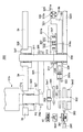
また、上述した実施の形態においては、制御装置81が調整モータ363及び差動歯車機構361を介してカム軸301の回転位相を調整するようにした場合について述べたが、本発明はこれに限らず、例えば図11に示すように、揺動用モータとしてのモータ371をカム軸301に直接駆動連結して、ハーモニックドライブ361を用いずにカム軸301を回動させる構成とし、制御装置81がモータ371を制御してカム軸301の回動を行なわせるようにしても良い。   In the above-described embodiment, the case where the control device 81 adjusts the rotational phase of the cam shaft 301 via the adjustment motor 363 and the differential gear mechanism 361 has been described. However, the present invention is not limited to this. For example, as shown in FIG. 11, a motor 371 as a swinging motor is directly connected to the camshaft 301 to rotate the camshaft 301 without using the harmonic drive 361, and the control device 81 is a motor. The cam shaft 301 may be rotated by controlling 371.

さらに、上述した実施の形態においては、カム304及びサブカム305により構築した共役カムを用いるようにした場合について述べたが、本発明はこれに限らず、共役カムを用いた場合と同様の角度範囲を得ることができるのであれば、サブカム305を用いることなくカム304だけで第2レバー325を揺動させたり、或いはエアーシリンダにより第2レバー325を揺動させるようにしても良い。   Furthermore, in the above-described embodiment, the case where the conjugate cam constructed by the cam 304 and the sub cam 305 is used has been described. However, the present invention is not limited to this, and the same angle range as that when the conjugate cam is used. If the second lever 325 can be swung only by the cam 304 without using the sub cam 305, or the second lever 325 can be swung by an air cylinder.

さらに、上述した実施の形態においては、3倍胴でなる印刷胴33を用いるようにした場合について述べたが、本発明はこれに限らず、2倍胴、4倍胴、6倍胴等でなる印刷胴を用いるようにしてもよい。   Further, in the above-described embodiment, the case where the printing cylinder 33 having a triple cylinder is used has been described. However, the present invention is not limited to this, and the double cylinder, the quadruple cylinder, the six cylinder, etc. A printing cylinder may be used.

1…デジタル印刷装置(シート搬送装置)、2…給紙装置、3…デジタル印刷ユニット、4…排紙装置、21、41…積載台、23…サッカー装置、25…負圧源、26…連続供給バルブ、27…間欠供給バルブ、31b…反転スイング装置(第3搬送部)、31bt…くわえ爪装置(第3保持装置)、31f…スイング装置、32…給紙側渡し胴、33…印刷胴(第2搬送部)、33a〜33c…印刷胴くわえ爪装置(第2保持装置)、34…インクジェットノズル部、35…インキ乾燥ランプ、36…第1の排紙側渡し胴、37…第2の排紙側渡し胴、38…紙取胴、39…反転前倍胴(第1搬送部)、39a…くわえ爪装置(第1保持装置)、40…デリバリーベルト、FB…フィーダボード、S1…シート、80…印刷モード選択スイッチ、81…制御装置(制御部)、82…搬送経路切替手段、93…シートサイズ検知部、94…位相検出センサ、300…スイング機構、301…カム軸、302、306、315、317、320、333、335、336、337…ベアリング、304…カム、305…サブカム、311…レバー軸、317、322…連結部材、332…カムフォロワ、325…第2レバー、327…セグメントギア、331…第3レバー、203…爪、205…爪台、361…ハーモニックドライブ(調整部)、371…モータ、363…調整モータ(調整部)、383…駆動モータ。   DESCRIPTION OF SYMBOLS 1 ... Digital printing apparatus (sheet conveyance apparatus), 2 ... Paper feeding apparatus, 3 ... Digital printing unit, 4 ... Paper discharge apparatus, 21, 41 ... Loading platform, 23 ... Soccer apparatus, 25 ... Negative pressure source, 26 ... Continuous Supply valve, 27 ... intermittent supply valve, 31b ... reverse swing device (third transport unit), 31bt ... gripper device (third holding device), 31f ... swing device, 32 ... paper feed side transfer cylinder, 33 ... printing cylinder (Second transport unit), 33a to 33c ... printing cylinder holding nail device (second holding device), 34 ... ink jet nozzle unit, 35 ... ink drying lamp, 36 ... first paper discharge side transfer cylinder, 37 ... second 38 ... paper take-up cylinder, 39 ... pre-reversing double cylinder (first transport unit), 39a ... gripper device (first holding device), 40 ... delivery belt, FB ... feeder board, S1 ... Sheet, 80 ... Print mode selection , 81 ... Control device (control unit), 82 ... Conveyance path switching means, 93 ... Sheet size detection unit, 94 ... Phase detection sensor, 300 ... Swing mechanism, 301 ... Cam shaft, 302, 306, 315, 317, 320, 333, 335, 336, 337 ... bearing, 304 ... cam, 305 ... sub cam, 311 ... lever shaft, 317, 322 ... coupling member, 332 ... cam follower, 325 ... second lever, 327 ... segment gear, 331 ... first 3 levers, 203 ... claws, 205 ... claw bases, 361 ... harmonic drive (adjustment unit), 371 ... motor, 363 ... adjustment motor (adjustment unit), 383 ... drive motor.

Claims (4)

シートを搬送するシート搬送装置において、
シートの端部を保持して搬送する第1保持装置を有する第1搬送部と、
前記第1搬送部により搬送されるシートの端部を保持して搬送する第2保持装置を有する第2搬送部と、
前記第1搬送部と前記第2搬送部との間で揺動自在に支持され、一方の端部が前記第1保持装置で保持されたシートの他方の端部を保持し、当該シートの他方の端部を前記第2搬送部の前記第2保持装置へ受け渡す第3保持装置を有する第3搬送部と、
シートの搬送方向長さに基づいて前記第3搬送部の揺動動作を制御する制御部と
を備えることを特徴とするシート搬送装置。
In a sheet conveying apparatus that conveys a sheet,
A first conveying unit having a first holding device that holds and conveys the edge of the sheet;
A second transport unit having a second holding device for transporting while holding an end of the sheet transported by the first transport unit;
The first conveyance unit and the second conveyance unit are swingably supported, and one end holds the other end of the sheet held by the first holding device, and the other end of the sheet A third conveying unit having a third holding device that delivers the end of the second conveying unit to the second holding device of the second conveying unit;
And a control unit that controls a swinging operation of the third conveyance unit based on a length in the conveyance direction of the sheet.
前記制御部は、
前記第3保持装置の速度を、
前記第1搬送部からシートを受け取るときに当該第1搬送部により搬送されるシートの速度と同速にし、
前記第2搬送部へシートを受け渡すときに当該第2搬送部の前記第2保持装置の速度と同速にするように制御すると共に、
前記第1搬送部からシートを受け取った後、前記第2搬送部へシートを受け渡すまでの間の前記第3搬送部の揺動速度をシートの搬送方向長に基づいて制御する
ことを特徴とする請求項1に記載のシート搬送装置。
The controller is
The speed of the third holding device,
When receiving a sheet from the first transport unit, the same speed as the sheet transported by the first transport unit,
When delivering a sheet to the second transport unit, the second transport unit is controlled to have the same speed as the second holding device, and
The swing speed of the third transport unit from when the sheet is received from the first transport unit to when the sheet is delivered to the second transport unit is controlled based on the length of the sheet in the transport direction. The sheet conveying apparatus according to claim 1.
前記第3搬送部の揺動速度を調整する調整部を備え、
前記調整部は、前記第3搬送部の駆動系に設けられた差動歯車機構と当該差動歯車機構を駆動して前記第3搬送部の揺動速度を調整する調整モータとを有し、
前記制御部は前記調整モータを制御する
ことを特徴とする請求項2に記載のシート搬送装置。
An adjustment unit for adjusting the swing speed of the third transport unit;
The adjustment unit includes a differential gear mechanism provided in a drive system of the third transport unit, and an adjustment motor that drives the differential gear mechanism to adjust the swing speed of the third transport unit,
The sheet conveying apparatus according to claim 2, wherein the control unit controls the adjustment motor.
前記第3搬送部を前記第1搬送部及び第2搬送部とは独立して揺動させる揺動用モータを備え、
前記制御部は、前記揺動用モータを制御する
ことを特徴とする請求項2に記載のシート搬送装置。
A swing motor for swinging the third transport unit independently of the first transport unit and the second transport unit;
The sheet conveying apparatus according to claim 2, wherein the control unit controls the swing motor.
JP2013092014A 2012-04-27 2013-04-25 Sheet conveyance device Pending JP2013241277A (en)

Priority Applications (1)

Application Number Priority Date Filing Date Title
JP2013092014A JP2013241277A (en) 2012-04-27 2013-04-25 Sheet conveyance device

Applications Claiming Priority (3)

Application Number Priority Date Filing Date Title
JP2012102321 2012-04-27
JP2013092014A JP2013241277A (en) 2012-04-27 2013-04-25 Sheet conveyance device

Publications (2)

Publication Number Publication Date
JP2013241277A true JP2013241277A (en) 2013-12-05
JP2013241277A5 JP2013241277A5 (en) 2016-05-19

Family

ID=49842596

Family Applications (1)

Application Number Title Priority Date Filing Date
JP2013092014A Pending JP2013241277A (en) 2012-04-27 2013-04-25 Sheet conveyance device

Country Status (1)

Country Link
JP (1) JP2013241277A (en)

Cited By (2)

* Cited by examiner, † Cited by third party
Publication number Priority date Publication date Assignee Title
JP2016129964A (en) * 2015-01-14 2016-07-21 株式会社小森コーポレーション Sheet carrying device
CN109626043A (en) * 2019-01-31 2019-04-16 晋江海纳机械有限公司 A kind of speed-changing conveying device and delivery method

Citations (3)

* Cited by examiner, † Cited by third party
Publication number Priority date Publication date Assignee Title
JPS5234802A (en) * 1975-07-24 1977-03-17 Cigardi Omc Sa Invertor for singleedouble side multi color offset printing machine
JPH058379A (en) * 1991-06-28 1993-01-19 Komori Corp Optimum tension processor in printing press
JP2003103753A (en) * 2001-10-01 2003-04-09 Shinohara Tekkosho:Kk Satellite type printing press

Patent Citations (3)

* Cited by examiner, † Cited by third party
Publication number Priority date Publication date Assignee Title
JPS5234802A (en) * 1975-07-24 1977-03-17 Cigardi Omc Sa Invertor for singleedouble side multi color offset printing machine
JPH058379A (en) * 1991-06-28 1993-01-19 Komori Corp Optimum tension processor in printing press
JP2003103753A (en) * 2001-10-01 2003-04-09 Shinohara Tekkosho:Kk Satellite type printing press

Cited By (3)

* Cited by examiner, † Cited by third party
Publication number Priority date Publication date Assignee Title
JP2016129964A (en) * 2015-01-14 2016-07-21 株式会社小森コーポレーション Sheet carrying device
CN109626043A (en) * 2019-01-31 2019-04-16 晋江海纳机械有限公司 A kind of speed-changing conveying device and delivery method
CN109626043B (en) * 2019-01-31 2024-04-09 晋江海纳机械有限公司 Variable speed conveying device and conveying method

Similar Documents

Publication Publication Date Title
JP6030979B2 (en) Sheet transport device
JP6224919B2 (en) Sheet processing device
JP6002622B2 (en) Transport device
JP6584255B2 (en) Sheet feeding device
JP6178598B2 (en) Printing device
US8899584B2 (en) Sheet reversing device
JP2013240997A (en) Conveying device
JP2013248879A (en) Digital sheet printing apparatus
JP2013241277A (en) Sheet conveyance device
JP2013240989A (en) Liquid transfer device
JP2014168962A (en) Printing apparatus
JP6202425B2 (en) Sheet digital printing machine
JP2013241274A (en) Swing device
JP2013241275A (en) Sheet processor
JP6104690B2 (en) Inverted sheet processing device
JP6133108B2 (en) Sheet feeding device
CN109311612B (en) Printing device
JP2013241276A (en) Sheet digital printer
JP2016129964A (en) Sheet carrying device
JP2013241267A (en) Conveyance device
JP6208973B2 (en) Sheet digital printing machine
JP6067464B2 (en) Sheet processing device
JP2013241002A (en) Sheet digital printing apparatus
JP2024013368A (en) sheet processing equipment
JP2013249205A (en) Printing apparatus

Legal Events

Date Code Title Description
A521 Written amendment

Free format text: JAPANESE INTERMEDIATE CODE: A523

Effective date: 20160325

A621 Written request for application examination

Free format text: JAPANESE INTERMEDIATE CODE: A621

Effective date: 20160325

A977 Report on retrieval

Free format text: JAPANESE INTERMEDIATE CODE: A971007

Effective date: 20170126

A131 Notification of reasons for refusal

Free format text: JAPANESE INTERMEDIATE CODE: A131

Effective date: 20170207

A521 Written amendment

Free format text: JAPANESE INTERMEDIATE CODE: A523

Effective date: 20170331

A02 Decision of refusal

Free format text: JAPANESE INTERMEDIATE CODE: A02

Effective date: 20170912