JP6202425B2 - Sheet digital printing machine - Google Patents
Sheet digital printing machine Download PDFInfo
- Publication number
- JP6202425B2 JP6202425B2 JP2013063514A JP2013063514A JP6202425B2 JP 6202425 B2 JP6202425 B2 JP 6202425B2 JP 2013063514 A JP2013063514 A JP 2013063514A JP 2013063514 A JP2013063514 A JP 2013063514A JP 6202425 B2 JP6202425 B2 JP 6202425B2
- Authority
- JP
- Japan
- Prior art keywords
- sheet
- cylinder
- printing
- engagement member
- ink jet
- Prior art date
- Legal status (The legal status is an assumption and is not a legal conclusion. Google has not performed a legal analysis and makes no representation as to the accuracy of the status listed.)
- Active
Links
Images


Landscapes
- Ink Jet (AREA)
Description
本発明は、シートに対してインクジェット方式によりデジタル印刷を行うシートデジタル印刷機に関する。 The present invention relates to a sheet digital printing machine that performs digital printing on a sheet by an inkjet method.
従来、シートに対してデジタル印刷可能な印刷機が提案されている(例えば、特許文献1参照)。この特許文献1の印刷機では、爪により記録媒体を正確に搬送しながらインクジェット方式により画像を記録することが開示されている。
Conventionally, a printing machine capable of digital printing on a sheet has been proposed (see, for example, Patent Document 1). In the printing machine of
ここで、シートに対してインクジェット方式により印刷を行うシートデジタル印刷機では、シートに対してインク滴を吐出することにより当該シートに画像を印刷する構成であり、シートに対するインク滴の着弾位置の精度が印刷品質に大きく影響する。特許文献1の構成においては、搬送中のシートに対して印刷を行うため、吐出したインク滴を高精度に着弾させるためにはインク滴を吐出するインクジェットノズル部のインクノズルヘッドをシートとの距離が極めて接近した最適位置に位置付けることが望ましい。
Here, in a sheet digital printing machine that prints on a sheet by an ink jet method, an image is printed on the sheet by ejecting ink droplets onto the sheet, and the accuracy of the ink droplet landing position on the sheet is Greatly affects print quality. In the configuration of
しかしながら、シートの厚さ(以下、これをシート厚と呼ぶ)が変更された場合、それまでのインクノズルヘッドとシートとの距離が最適であったとしても、インクノズルヘッドとシートとの距離が変化してしまい、高品質な印刷を行うことができないという問題があった。 However, when the thickness of the sheet (hereinafter referred to as the sheet thickness) is changed, even if the distance between the ink nozzle head and the sheet so far is optimum, the distance between the ink nozzle head and the sheet is There has been a problem that high quality printing cannot be performed due to the change.
本発明はかかる問題を解決するためになされたものであり、どの様なシート厚のシートに対してもインクノズルヘッドを最適な位置に位置付けて高品質な印刷を行なうことができるシートデジタル印刷機を提案しようとするものである。 The present invention has been made to solve such a problem, and is a sheet digital printing machine capable of performing high-quality printing by positioning an ink nozzle head at an optimum position for any sheet thickness. Is to try to propose.
かかる課題を解決するため請求項1の発明においては、シートを搬送する搬送部と、前記搬送部により搬送されるシートにインク滴を吐出して印刷を行うインクジェットノズル部と、前記インクジェットノズル部を前記搬送部に対して接近離反させ、印刷位置における前記インクジェットノズル部の前記搬送部に対する位置を調整するインクジェットノズル調整手段と、シートのシート厚さに基づいて前記インクジェットノズル調整手段を制御する制御手段と、前記インクジェットノズル部のノズルヘッドをシートの印刷面に対して接近離反させる方向へ移動自在に保持するヘッド保持ユニットと、前記ヘッド保持ユニットを摺動自在に保持し、当該ヘッド保持ユニットをフレームの外側のメンテナンス位置へ案内するガイドレールとを備え、前記インクジェットノズル調整手段は、前記ヘッド保持ユニットに設けられ、当該ヘッド保持ユニットに対して移動自在に支持された第1係合部材と当該第1係合部材を移動させる駆動手段とを有するインクジェットノズル調整装置と、前記第1係合部材と対向した状態で前記フレームに取り付けられ、前記第1係合部材と係合する第2係合部材とを具備しているようにする。
In order to solve such a problem, in the invention of
また請求項2の発明において、前記第1係合部材は係合孔を有し、前記第2係合部材は、前記係合孔に係合するガイドピンを有しているようにすることができる。
In the invention of
さらに請求項3の発明において、前記ガイドレールは、前記第1係合部材が前記駆動手段によって駆動されて移動する方向と直交する方向に、前記ヘッド保持ユニットを摺動自在に保持するようにすることができる。
Furthermore, in the invention of
請求項1の発明によれば、シート厚さに基づいて調整手段を制御することによりシートとノズルヘッドとの間を常に最適な距離に保つことができるので高品質な印刷を行なうことができる。 According to the first aspect of the invention, by controlling the adjusting means based on the sheet thickness, it is possible to always maintain an optimum distance between the sheet and the nozzle head, so that high quality printing can be performed.
次に、本発明の一実施の形態について図面を参照して説明する。 Next, an embodiment of the present invention will be described with reference to the drawings.
<デジタル印刷装置の構成>
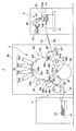
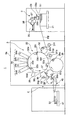
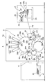
図1に示すように、シートデジタル印刷機としてのデジタル印刷装置1は、供給部としての給紙装置2、処理部としてのデジタル印刷ユニット3及び排出部としての排紙装置4を備える。
<Configuration of digital printing device>
As shown in FIG. 1, a
給紙装置2には、複数のシートS1が積載された積載台21および、その積載台21の最上段のシートS1をフィーダボードFBへ搬送するサッカー装置23が設けられている。サッカー装置23は、第1吸23aおよび第2吸23bを備え、第1吸23aおよび第2吸23bが連続供給バルブ26および間欠供給バルブ27を介して負圧源25と接続されている。
The
連続供給バルブ26および間欠供給バルブ27は、共に第1吸23aおよび第2吸23bの負圧源25からの吸引を断接するものであるが、後述するように吸引を断接するタイミングがそれぞれ異なっている。
The
フィーダボードFBのシート搬送方向先端側には、デジタル印刷ユニット3のフレーム3aに揺動自在に支持され、シートS1の一方の端部である先端(くわえ側端部)をくわえて保持する図示しないくわえ爪装置を備えたスイング装置31fが配設されている。スイング装置31fには給紙側渡し胴32が対向して配置され、その給紙側渡し胴32がフレーム3aに回転自在に支持されている。
On the front end side in the sheet conveying direction of the feeder board FB, it is supported by the
給紙側渡し胴32には、スイング装置31fのくわえ爪装置により受け渡されるシートS1の先端をくわえた状態で保持するくわえ爪装置32aが設けられている。なおデジタル印刷ユニット3では、スイング装置31fおよび給紙側渡胴32により上流側シート搬送装置を構成している。
The feeding
給紙側渡し胴32には、スイング装置31fよりもシート搬送方向下流側に搬送部としての印刷胴33が対接配置され、その印刷胴33がフレーム3aに回転自在に支持されている。印刷胴33は、その直径が給紙側渡し胴32の3倍の直径を有し、給紙側渡し胴32のくわえ爪装置32aからシートS1の先端を受け取って保持する印刷胴くわえ爪装置33a、33b、33cと、この印刷胴くわえ爪装置33a、33b、33cに対応して設けられシートS1を支持する支持面33d、33e、33fとを備え、印刷胴くわえ爪装置と支持面との組を3組設けた3倍胴として構成されている。ここで、シートS1を保持する印刷胴くわえ爪装置33a、33b、33cは円周方向に互いに120度位相をずらした状態で設けられている。
A
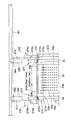
図2に示されるように、印刷胴33の支持面33d、33e、33fには複数の吸引用孔33gが形成されており、その複数の吸引用孔33gが図示しない負圧源と接続されている。また、印刷胴33の軸33pの一方にはギア270が固定されており、図示しない本機駆動モータと駆動連結されている。
As shown in FIG. 2, a plurality of
図1に示されるように、印刷胴33の吸引孔33gによるシートS1の吸引作動範囲は、印刷胴33の給紙側渡し胴32との対接部分よりもシート搬送方向下流側近傍の吸引開始位置33iから第1の排紙側渡し胴36との対接部分よりもシート搬送方向上流側近傍の吸引終了位置33jまでの間であり、この吸引作動範囲においてシートS1の全面は印刷胴33の支持面33d、33e、33fに吸着される。
As shown in FIG. 1, the suction operation range of the sheet S <b> 1 by the
印刷胴33の給紙側渡し胴32との対接部分よりもシート搬送方向下流側には、当該印刷胴33の周面に対向してインクジェットノズル部34が配置されている。
An
インクジェットノズル部34には、互いに異なる色のインクをセットした複数のインクジェットノズルヘッド34a〜34dが印刷胴33の周面に沿ってシート搬送方向に並設され、それぞれが印刷胴33の周面を指向している。インクジェットノズルヘッド34a〜34dは、印刷胴33の複数の吸引用孔33gによって支持面33d、33e、33fに全面吸着されたシートS1との隙間が僅かな間隔となるよう印刷胴33に近接して配設されている。なお、印刷胴33、インクジェットノズル部34によりシート印刷装置を構成しており、インクジェットノズルヘッド34a〜34dと対向する印刷胴33の周面部分がシートS1に印刷を施すための印刷領域33kを形成している。
In the
次に、図2乃至図5を用いてインクジェットノズル部34の支持構成を説明する。ここでは特にインクジェットノズルヘッド34dの支持構成について説明するが、インクジェットノズルヘッド34a〜34cの支持構成もインクジェットノズルヘッド34dと同じである。
Next, the support structure of the
フレーム3a、3aには、印刷胴33の上方に設けられ当該印刷胴33の軸方向に延び、その両端を当該フレーム3a、3aの外側へ延ばしたガイドレール281が図示しない支持部材を介して固定されている。ガイドレール281にはそれぞれスライダ282、284が摺動自在に支持されており、各スライダ282、284にはホルダ283、285が固定されている。
ホルダ283、285には、一端にインクジェットノズル着脱装置としてのエアーシリンダ276、278のシリンダ本体276a、278aが支持されたステーST1、ST2が固定されている。エアーシリンダ276、278のピストンロッド276b、278bには支持板34dpの両端部が固定され、この支持板34dpにはインクジェットノズルヘッド34dが支持されている。
To the
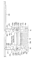
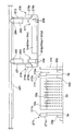
インクジェットノズルヘッド34dは、エアーシリンダ276、278により着脱自在とされ、図2および図1の実線に示される印刷胴33に近接する印刷位置と、図3および図1の破線に示される印刷位置から印刷胴33の半径方向外側へ離反して退避する退避位置との間で移動可能に支持されている。また、インクジェットノズルヘッド34dは、ガイドレール281に沿って移動させることにより、図3に示される退避位置と図4に示されるフレーム3aの外側のメンテナンス位置との間で移動可能に支持されている。
The ink
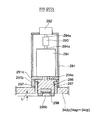
図2の275、277は、支持板34dpの両端部に設けられインクジェットノズルヘッド34dの印刷位置における印刷胴33に対する位置を調整するインクジェットノズル調整装置であり、図5にその詳細構成が示されている。図5を用いてインクジェットノズル調整装置275、277の詳細構成を説明するが、両者は同一構造であるため、ここではインクジェットノズル調整装置275についてのみ説明する。
275 and 277 in FIG. 2 are ink jet nozzle adjusting devices that are provided at both ends of the support plate 34dp and adjust the position of the ink
支持板34dpには、インクジェットノズル調整装置275、277における筐体291の外周壁291bが固定され、当該外周壁291bの内側には内周に雌ねじが設けられた雌ねじ部297が固定されている。また、筐体291の内部には保持プレート291aが固定されており、当該保持プレート291aには駆動手段としてのモータ294が固定されている。モータ294のモータ軸294aの一端には、雄ねじ部材296が当該モータ軸294aと一体に回転するとともに当該モータ軸294aの軸方向へ移動自在に支持されている。この雄ねじ部材296は雌ねじ部297と螺合し、その先端には係合孔298bが形成された第1係合部材298が固定されている
An outer
また、筐体291の上端部にはポテンションメータ292が設けられ、当該ポテンションメータ292とモータ294とはモータ軸294aおよびカップリング293を介して連結されている。
A
一方、図3に示されるように、左右のフレーム3a、3aの上端部には、第2係合部材271、272がそれぞれ設けられている。第2係合部材271、272は、フレーム3aに固定された本体271a、272aと、本体271a、272aの上端面から所定量だけ突出しインクジェットノズル調整装置275、277の係合孔298b、298bに挿入されるガイドピン271b、272bとによって構成されている。また本体271a及び272aの上端面と印刷胴33の外周面とはほぼ同じ高さに揃えられている。なお、スライダ282、284、ホルダ283、285、ステーST1、ST2、エアーシリンダ276、278、支持板34dpにより、インクジェットノズル部34のノズルヘッド34a〜34dをシートS1の印刷面に対して接近離反させる方向へ移動自在に保持するヘッド保持ユニットを構成している。また、インクジェットノズル調整装置275、277と第2係合部材271、272とによりインクジェットノズル調整手段を構成している。
On the other hand, as shown in FIG. 3, second engaging
印刷胴33のインクジェットノズル部34による印刷領域33kよりもシート搬送方向下流側には、印刷胴33に対接配置され、シートS1に赤外線や紫外線などの光を照射して当該シートS1上に印刷されたインクを乾燥させる乾燥装置としてのインキ乾燥ランプ35が設けられている。ここで、乾燥とは熱エネルギーを与えてインクの水分を蒸発させることやインクを硬化させることを含むものであり、固化と言い換えることができる。
The
印刷胴33には、インクジェットノズル部34よりもシート搬送方向下流側に、第1の排紙側渡し胴36が対接配置され、その第1の排紙側渡し胴36がフレーム3aに回転自在に支持されている。第1の排紙側渡し胴36には、印刷胴33により搬送されるシートS1の先端を印刷胴くわえ爪装置33a、33b、33cから受け取って保持するくわえ爪装置36aが設けられている。
A first paper discharge
第1の排紙側渡し胴36の印刷胴33との対接部分よりもシート搬送方向下流側には、第2の排紙側渡し胴37が第1の排紙側渡し胴36と対接配置され、その第2の排紙側渡し胴37がフレーム3aに回転自在に支持されている。第2の排紙側渡し胴37には、第1の排紙側渡し胴36により搬送されるシートS1の先端を受け取って保持するくわえ爪装置37aが設けられている。
A second paper discharge
第2の排紙側渡し胴37の第1の排紙側渡し胴36との対接部分よりもシート搬送方向下流側には紙取胴38が対接配置され、その紙取胴38がフレーム3aに回転自在に支持されている。紙取胴38には、第2の排紙側渡し胴37により搬送されるシートS1の先端を受け取って保持するくわえ爪装置38aが設けられている。
A paper take-up
紙取胴38の下方には、シートS1を搬送するベルトコンベア状のデリバリーベルト40が配設されている。デリバリーベルト40のシート搬送方向先端側には、デジタル印刷ユニット3によりデジタル印刷処理の施されたシートS1を積載する積載台41が設けられている。なお、紙取胴38、デリバリーベルト40、積載台41により排紙装置4を構成し、紙取胴38およびデリバリーベルト40により搬送されるシートS1の経路がシート排出経路を構成する。
Below the
第2の排紙側渡し胴37の紙取胴38との対接部分よりもシート搬送方向下流側には、反転前倍胴39が対接配置され、その反転前倍胴39がフレーム3aに回転自在に支持されている。反転前倍胴39は、第2の排紙側渡し胴37の2倍の直径を有する2倍胴であり、第2の排紙側渡し胴37により搬送されるシートS1の先端を受け取って保持するくわえ爪装置39aが一組設けられている。
A pre-reverse
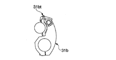
反転前倍胴39の第2の排紙側渡し胴37との対接部分よりもシート搬送方向下流側には、図6に示されるように、シートS1の他方の端部としての後端(尻側端部)を受け取って保持するくわえ爪装置31btを備えた反転スイング装置31bが対向して配置されている。なお、反転スイング装置31bはシートS1の表裏を反転させる反転部を構成する。
As shown in FIG. 6, as shown in FIG. 6, the rear end (the other end of the sheet S <b> 1) is located downstream of the portion of the
反転スイング装置31bは、印刷胴33の第1の排紙側渡し胴36との対接部分よりも印刷胴33の回転方向下流側かつ給紙側渡し胴32との対接部分よりも印刷胴33の回転方向上流側において印刷胴33に対向して配置されている。そして、この反転スイング装置31bは、反転前倍胴39により搬送されるシートS1の後端を受け取る破線で示された受取位置(図1)と、印刷胴33の印刷胴くわえ爪装置33a、33b、33cにシートS1の後端を受け渡す実線で示された受渡位置(図1)との間で揺動自在にフレーム3aに支持されている。なお、第1の排紙側渡し胴36、第2の排紙側渡し胴37、反転前倍胴39、反転スイング装置31bにより反転機構を構成し、第1の排紙側渡し胴36、第2の排紙側渡し胴37、反転前倍胴39、反転スイング装置31bにより搬送されるシートS1の経路がシート反転経路を構成する。
The reversing
第2の排紙側渡し胴37のくわえ爪装置37aは、紙取胴38のくわえ爪装置38aと反転前倍胴39のくわえ爪装置39aとに選択的にシートS1を受け渡すことが可能に駆動される。また、紙取胴38のくわえ爪装置38aは、第2の排紙側渡し胴37により搬送されるシートS1の先端を選択的に受け取ることが可能に駆動され、これらくわえ爪装置37a、38aはシートS1の搬送先を排紙装置4または反転スイング装置31bに切替える、すなわち、シートS1の搬送経路をシート排出経路またはシート反転経路に切替える搬送経路切替手段82(図7)を構成する。
The
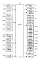
<デジタル印刷装置の制御系の構成>
図7に示すように、デジタル印刷装置1は、全体を統括制御するためのCPU(Central processing Unit)構成でなる制御手段としての制御装置100を備えている。制御装置100には、シートS1の片面だけにデジタル印刷処理を施す片面印刷モード、シートS1の表面および裏面の両面にデジタル印刷処理を施す両面印刷モードの何れかを作業者に選択させる印刷モード選択スイッチ101、印刷胴33を回転駆動させる駆動モータ302、印刷胴33の位相を検出する位相検出装置としてのロータリエンコーダ304、作業者による入力或いは検出器による検出によりシートS1の厚さが入力されるシート厚さ入力手段301、連続供給バルブ26、間欠供給バルブ27、搬送経路切替手段82、インクジェットノズル部34の各インクジェットノズルヘッド34a〜34d、各インクジェットノズルヘッド34a〜34d用のノズル着脱装置3401a〜3401d、各インクジェットノズルヘッド34a〜34d用のノズル調整装置3402a〜3402d、各インクジェットノズルヘッド34a〜34d用のポテンショメータ292a〜292d、各インクジェットノズルヘッド34a〜34d用のヘッド位置調整スイッチ303a〜303d、インキ乾燥ランプ35が接続されている。なお、ヘッド位置調整スイッチ303a〜303dは、各インクジェットノズルヘッド34a〜34dの位置を作業者がマニュアルで調整するスイッチである。
<Configuration of control system of digital printing device>
As shown in FIG. 7, the
<デジタル印刷装置の印刷動作>
このように構成されたデジタル印刷装置1の印刷動作について、片面印刷モードが選択された場合と、両面印刷モードが選択された場合とに分けて説明する。
<Printing operation of digital printing device>
The printing operation of the
図1に示されるように、作業者の印刷モード選択スイッチ101の操作により片面印刷モードが選択されると、制御装置100は連続供給バルブ26を作動させ、これにより第1吸23aおよび第2吸23bが積載台21のシートS1を吸着しフィーダボードFBへ搬送する。
As shown in FIG. 1, when the single-sided printing mode is selected by the operator's operation of the printing
連続供給バルブ26は、印刷胴33の1回転中に当該印刷胴33に設けられた印刷胴くわえ爪装置33a、33b、33cの数と同じ枚数のシートS1を供給するタイミング、換言すると、印刷胴33における各くわえ爪装置33a、33b、33cと給紙側渡し胴32のくわえ爪装置32aとが対向するタイミング(周期)ごとに連続供給バルブ26が「開」して第1吸23aおよび第2吸23bの負圧源25からの吸引が行なわれるように作動する。このように、印刷胴33の全ての印刷胴くわえ爪装置33a、33b、33cがシートS1をくわえるように当該シートS1を供給することを連続給紙と呼び、連続給紙における連続供給バルブ26の開閉周期を第1の周期と呼ぶ。これにより、サッカー装置23はシートS1を第1の周期でフィーダボードFBへ搬送する。
The
フィーダボードFBにより搬送されるシートS1は、その先端がスイング装置31fのくわえ爪装置によって保持された後に当該スイング装置31fの揺動により給紙側渡し胴32へ向かって搬送され、その給紙側渡し胴32のくわえ爪装置32aに当該シートS1の先端がくわえ替えされる。
The sheet S1 conveyed by the feeder board FB is conveyed toward the sheet feeding
給紙側渡し胴32の回転に伴って搬送されるシートS1は、印刷胴33との対接部分において給紙側渡し胴32のくわえ爪装置32aから印刷胴33の印刷胴くわえ爪装置33a〜33cの何れかにその先端がくわえ替えされた後、印刷胴33の回転とともに搬送される。印刷胴33は吸引開始位置33iから回転方向下流側において吸引孔33gに吸引力が作用するので、シートS1が吸引開始位置33iを通過すると、当該シートS1の全面は支持面33d、33e、33fに吸着され密着する。
The sheet S1 conveyed along with the rotation of the sheet feeding
印刷胴33により搬送されるシートS1の表面には、インクジェットノズル部34のインクジェットノズルヘッド34a〜34dから微滴化されたインクが吐出されることによりデジタル印刷処理が施される。シートS1は印刷胴33の支持面33d〜33fに密着しているため、インクジェットノズルヘッド34a〜34dとの間の微小間隔が維持された状態で搬送される。この微小間隔が維持されることにより吐出されたインクをシートに高精度で着弾させることができ、高品質な印刷を行うことができる。インクジェットノズル部34による印刷が行われたシートS1は、印刷胴33とインキ乾燥ランプ35との間を通過し、当該インキ乾燥ランプ35からの光が照射され、これによりシートS1のインクが乾燥する。その後シートS1は第1の排紙側渡し胴36へ搬送される。
Digital printing processing is performed on the surface of the sheet S <b> 1 conveyed by the
シートS1は、吸引開始位置33iから吸引終了位置33jまでの間の吸引作動範囲において、印刷胴33の支持面33d、33e、33fに密着しているため、インキ乾燥ランプ35からシートS1の全面に均一に光が照射され、むらの無いインク乾燥が行なわれる。
Since the sheet S1 is in close contact with the support surfaces 33d, 33e, and 33f of the
図8に示すように、印刷胴33と第1の排紙側渡し胴36との対接部分において印刷胴33の印刷胴くわえ爪装置33a〜33cから第1の排紙側渡し胴36のくわえ爪装置36aにシートS1の先端がくわえ替えされる。その際、シートS1の先端側は吸引終了位置33jを通過しているため吸引孔33gからの吸引力が無くなっており、シートS1が支持面33d、33e、33fから容易に剥がされ、スムーズなくわえ替えを行なうことができる。
As shown in FIG. 8, in the contact portion between the
その後、図9に示すように、第1の排紙側渡し胴36のくわえ爪装置36aに保持されたシートS1は、第1の排紙側渡し胴36と第2の排紙側渡し胴37との対接部分において、第1の排紙側渡し胴36のくわえ爪装置36aから第2の排紙側渡し胴37のくわえ爪装置37aにその先端がくわえ替えされる。
After that, as shown in FIG. 9, the sheet S <b> 1 held by the
片面印刷モードの場合、制御装置100は、ロータリエンコーダ304に基づいて全てのシートS1が第2の排紙側渡胴37から紙取胴38へ受け渡されるように搬送経路切替手段82を制御する。すなわち、シートS1の先端が第2の排紙側渡し胴37と紙取胴38との対接部分に位置付けられる位相において、第2の排紙側渡し胴37のくわえ爪装置37aがシートS1の先端の保持を解除するとともに、紙取胴38のくわえ爪装置38aがシートS1の先端をくわえて保持する。これにより片面に印刷が施されたシートS1は全て第2の排紙側渡し胴37から紙取胴38へくわえ替えされて搬送される。
In the single-sided printing mode, the
紙取胴38にくわえ替えされたシートS1は、デリバリーベルト40の上方に紙取胴38のくわえ爪装置38aが位置したタイミングで当該くわえ爪装置38aによる保持が解除され、デリバリーベルト40上に載せられる。
The sheet S1 that has been replaced by the paper take-up
デリバリーベルト40上に載せられたシートS1は当該デリバリーベルト40の走行とともに搬送され、表面にデジタル印刷処理の施されたシートS1が排紙装置4の積載台41上に排出される。
The sheet S1 placed on the
一方、作業者の印刷モード選択スイッチ101の操作により両面印刷モードが選択された場合、制御装置100は間欠供給バルブ27を作動させ、これにより、第1吸23aおよび第2吸23bにより積載台21のシートS1を吸着しフィーダボードFBへ搬送する。
On the other hand, when the double-sided printing mode is selected by the operator's operation of the printing
間欠供給バルブ27は、連続供給のタイミングに対して1枚おきのタイミングでシートS1を供給するタイミング、換言すると、印刷胴33における各くわえ爪装置33a、33b、33cと給紙側渡し胴32のくわえ爪装置32aとが対向するタイミング(周期)で、バルブが「開」、「閉」、「開」、「閉」、…、となるように制御される。これは、連続供給の周期の2倍の周期である。このように、印刷胴33の印刷胴くわえ爪装置33a、33b、33cが一つおきにシートS1をくわえるように当該シートS1を供給することを間欠給紙と呼び、間欠給紙における間欠供給バルブ27の開閉周期を第2の周期と呼ぶ。これにより、サッカー装置23はシートS1を第2の周期でフィーダボードFBへ搬送する。
The
サッカー装置23によりフィーダボードFBへ送り出されたシートS1は、片面印刷モードの場合と同様にスイング装置31fおよび給紙側渡し胴32を介して印刷胴33に受け渡されるが、シートS1は間欠給紙のタイミングで送り出されているため、印刷胴33の印刷胴くわえ爪装置33a〜33cは一つおきに給紙側渡し胴32から搬送される新規なシートS1を受取る。
The sheet S1 sent to the feeder board FB by the
その後、シートS1はインクジェットノズル部34に搬送され、その一方の面(表面)に表面用の印刷が施される。ここで、制御装置100は、ロータリエンコーダ304からの検出信号に基づいて、印刷胴33の印刷胴くわえ爪装置33a〜33cの一つおきに保持された新規なシートS1に対して印刷を施し、シートS1を保持していない印刷胴くわえ爪装置33a〜33cに対応する支持面33d〜33fに対して印刷を行なわないようにインクジェットノズル部34の各インクジェットノズルヘッド34a〜34dを制御する。
Thereafter, the sheet S1 is conveyed to the
両面印刷モードの場合には、制御装置100は、インクジェットノズル部34により表面に印刷が施されたシートS1が、第2の排紙側渡し胴37から紙取胴38へ受け渡されずに、反転前倍胴39に受け渡されるように、搬送経路切替手段82を制御する。
In the double-sided printing mode, the
すなわち、両面印刷モードの場合においては、表面に印刷が施されているが他方の面(裏面)にはデジタル印刷処理されていないシートS1が第2の排紙側渡し胴37と紙取胴38との対接部分に位置付けられる位相において、第2の排紙側渡し胴37のくわえ爪装置37aの爪は開かずに閉じたままの状態、すなわちシートS1の先端を保持した状態が維持されるとともに、紙取胴38のくわえ爪装置38aの爪は閉じずに開いた状態が維持される。
That is, in the case of the duplex printing mode, the sheet S1 that has been printed on the front surface but not digitally printed on the other surface (back surface) is the second discharge
これにより表面のみに印刷が施されたシートS1は第2の排紙側渡し胴37から紙取胴38へくわえ替えされることなく反転前倍胴39へ搬送される。すなわち、第2の排紙側渡し胴37と反転前倍胴39との対接部分において反転前倍胴39くわえ爪装置39aの爪を閉じてシートS1の先端を保持させるとともに、第2の排紙側渡し胴37のくわえ爪装置37aの爪を開いてシートS1の先端の保持を解除し、図10に示すように、第2の排紙側渡し胴37のくわえ爪装置37aから反転前倍胴39のくわえ爪装置39aにシートS1の先端をくわえ替えさせる。
As a result, the sheet S1 printed only on the front surface is conveyed from the second paper discharge
図11に示すように、反転前倍胴39の回転とともに搬送されるシートS1は、反転前倍胴39の回転とともに搬送され、反転スイング装置31bが実線で示される受渡位置から破線で示される受取位置に揺動し、シートS1の後端を当該反転スイング装置31bの反転くわえ爪装置31btにより保持すると同時に、反転前倍胴39のくわえ爪装置39aによるシートS1の先端に対する保持を解除する。これにより、シートS1は反転前倍胴39から反転スイング装置31bにくわえ替えされる。
As shown in FIG. 11, the sheet S1 conveyed along with the rotation of the pre-inversion
そして、図12に示すように、反転スイング装置31bの破線で示す受取位置から実線で示す受渡位置への揺動によりシートS1は後端(紙尻側端部)を先頭にして印刷胴33に向けて搬送され、反転スイング装置31bの反転くわえ爪装置31btから印刷胴33の印刷胴くわえ爪装置33a〜33cの何れかに表裏反転したシートS1の後端がくわえ替えされる。
Then, as shown in FIG. 12, the sheet S <b> 1 is placed on the
ここで、印刷胴33の印刷胴くわえ爪装置33a〜33cは給紙側渡し胴32から搬送される新規なシートS1を一つおきに保持しているのであるが、反転スイング装置31bは新規なシートS1を保持しない印刷胴くわえ爪装置33a〜33cと対向するタイミングで受渡位置へ位置付けられ、反転くわえ爪装置31btからシートS1の後端を印刷胴くわえ爪装置33a〜33cへ受け渡す。これにより、印刷胴33の印刷胴くわえ爪装置33a〜33cには、給紙側渡し胴32から受け渡された新規なシートS1と反転くわえ爪装置31btから受け渡された表裏反転状態のシートS1とが交互に保持され、インクジェットノズル部34へ搬送される。
Here, the printing cylinder holding
このとき反転スイング装置31bの反転くわえ爪装置31btから受け渡された表裏反転状態のシートS1は、インクジェットノズル部34により既にデジタル印刷処理の施された表面(デジタル印刷処理済みの面)が印刷胴33の支持面33d、33e、33fと対接し、シートS1の裏面(デジタル印刷未処理の面)が露出した状態で、シートS1の後端が印刷胴33の印刷胴くわえ爪装置33a〜33cにより保持された状態のまま搬送され、すなわちシートS1が表裏反転状態で搬送されインクジェットノズル部34によりシートS1の裏面にデジタル印刷処理が施される。
At this time, the sheet S1 in the front and back reversed state transferred from the reversing gripper device 31bt of the reversing
ここで、制御装置100は、ロータリエンコーダ304からの検出信号に基づいて反転スイング装置31bの反転くわえ爪装置31btから受け渡された表裏反転状態のシートS1に対しては裏面用の印刷を施し、印刷胴33の印刷胴くわえ爪装置33a〜33cの一つおきに保持された新規なシートS1に対しては表面用の印刷を施すようにインクジェットノズル部34の各インクジェットノズルヘッド34a〜34dを制御する。これにより、インクジェットノズルヘッド34a〜34dは、印刷胴33により交互に保持された新規なシートS1および表裏反転状態のシートS1に対応して表面用の印刷と裏面用の印刷を交互に行うことになる。
Here, the
その後、裏面に裏面用の印刷が施されたシートS1は、片面印刷モードの場合と同様に、第1の排出側渡し胴36、第2の排紙側渡し胴37、紙取胴38を順次介してデリバリーベルト40から積載台41へ排出される。
Thereafter, the sheet S1 printed on the back side is printed on the first discharge
以上がデジタル印刷装置1における片面印刷モードおよび両面印刷モードの印刷動作である。次に、インクジェットノズルヘッド34a〜34dのシートS1に対するヘッド位置調整について説明する。
The above is the printing operation in the single-sided printing mode and the double-sided printing mode in the
各インクジェットノズルヘッド34a〜34d用のヘッド位置調整スイッチ303a〜303dが作業者により操作され、シート厚さ入力手段301に対して作業者或いは検出器によりシートS1の厚さが入力されると、制御装置100はインクジェットノズルヘッド34a〜34dのポテンショメータ292a〜292dに基づきヘッド位置調整装置としてのモータ294(図5)の作動量を算出し、その作動量に従って当該モータ294を作動させる。
When the head
モータ294を作動させると、図5に示されるように、モータ軸294aが雄ねじ部材296を伴って回転する。雄ねじ部材296の回転により雌ねじ部297とのねじ作用により当該雄ねじ部材296がモータ軸294aの軸方向に移動し、支持板34dpからの突出量Lが調整される。なお、このインクジェットノズルヘッド34a〜34dの調整作業は、印刷作業に先立って、インクジェットノズルヘッド34a〜34dが退避位置(図3)にある状態で行われる。
When the
このようして、雄ねじ部材296の支持板34dpからの突出量Lが調整された後、インクジェットノズルヘッド34a〜34dを退避位置にある状態からエアーシリンダ276、278を作動させると、支持板34dpがインクジェットノズルヘッド34a〜34dおよびインクジェットノズル調整装置275、277を伴って印刷胴33に近接する方向へ移動する。
Thus, after the protrusion amount L of the
この移動中に第1係合部材298の係合孔298bが第2係合部材271、272のガイドピン271b、272bに係合し、その後、第1係合部材298の下端面が第2係合部材271、272の本体271a及び272aの上端面に押圧される。係合孔298bとガイドピン271b、272bとの係合、および、エアーシリンダ276、278による第1係合部材298の下端面の本体271aおよび272aの上端面に対する押圧により、支持板34dp、すなわちインクジェットノズルヘッド34a〜34dはフレーム3a、3bに一体的に固定される。
During this movement, the
このように突出量Lの調整により、本体271a及び272aの上端面に対するインクジェットノズルヘッド34a〜34dのヘッド位置が調整されるので、すなわちインクジェットノズルヘッド34a〜34dの印刷胴33に対するヘッド位置が調整される。このようにして、インクジェットノズルヘッド34a〜34dとシートS1との間の距離が予め定められた距離となるように調整される。
By adjusting the protrusion amount L in this way, the head positions of the inkjet nozzle heads 34a to 34d with respect to the upper end surfaces of the
これにより、シートS1の厚さが変更されてもインクジェットノズルヘッド34a〜34dとシートS1とは所定の微小間隔が維持され、インクジェットノズルヘッド34a〜34dから吐出されたインクをシートS1に高精度で着弾させることができ、高品質な印刷を行うことができる。 Thereby, even if the thickness of the sheet S1 is changed, a predetermined minute gap is maintained between the inkjet nozzle heads 34a to 34d and the sheet S1, and the ink discharged from the inkjet nozzle heads 34a to 34d is applied to the sheet S1 with high accuracy. Landing can be achieved, and high-quality printing can be performed.
制御装置100は、シート厚さ入力手段301により入力されたシート厚に基づいてインクジェットノズルヘッド34a〜34dの位置を自動的に調整するが、必要に応じて作業者が各インクジェットノズルヘッド34a〜34d用のヘッド位置調整スイッチ303a〜303dを操作してインクジェットノズルヘッド34a〜34dの位置を微調整することができる。
The
最後に、デジタル印刷装置1による印刷が終了し、インクジェットノズルヘッド34a乃至34dのメンテナンス作業を行なう場合には、図3に示される退避位置に位置付けられたインクジェットノズルヘッド34a乃至34dをガイドレール281に沿って図4に示されるメンテナンス位置へ移動させる。メンテナンス位置においてインクジェットノズルヘッド34a乃至34dはフレーム3aの外側に位置付けられるため、メンテナンス作業を容易に行うことができ、作業者の負担が大幅に軽減される。
Finally, when printing by the
<他の実施の形態>
なお、上述した実施の形態においては、シート厚調整処理を退避位置(図3)にある場合に行うようにした場合について述べたが、本発明はこれに限らず、メンテナンス位置(図4)にある場合に行ったり、或いは、インクジェットノズルヘッド34d(34a〜34d)側のインクジェットノズル調整装置275、277と、印刷胴33側の第2係合部材271、272とが互いに結合された印刷位置(図2)において行うようにしても良い。
<Other embodiments>
In the above-described embodiment, the case where the sheet thickness adjustment process is performed in the retracted position (FIG. 3) has been described. However, the present invention is not limited to this, and the maintenance position (FIG. 4) is used. In some cases, or a printing position in which the inkjet
さらに、上述した実施の形態においては、シート反転機構を第1の排紙側渡し胴36、第2の排紙側渡し胴37、反転前倍胴39、反転スイング装置31bにより構成されるようにしたが、くわえ爪装置を有する胴やスイングのみで構成すれば、胴の大きさや数は本実施例のものに限定されない。要は、シートS1をこれらくわえ爪装置のみのくわえ替えで搬送できるように構成すればよい。
Further, in the above-described embodiment, the sheet reversing mechanism is configured by the first discharge
また、上述した実施の形態においては、3倍胴でなる印刷胴33を用いるようにした場合について述べたが、本発明はこれに限らず、2倍胴、4倍胴、6倍胴等でなる印刷胴を用いるようにしてもよい。
In the above-described embodiment, the case where the
さらに、上述した実施の形態においては、印刷胴33を用いるようにした場合について述べたが、本発明はこれに限らず、水平にシートS1を搬送しながらインクジェットノズル部34によりデジタル印刷を行うような搬送台(図示せず)を用いるようにしても良い。
Furthermore, in the above-described embodiment, the case where the
さらに、上述した実施の形態においては、印刷胴として3倍胴でなる印刷胴33を用いるようにした場合について述べたが、本発明はこれに限らず、4色のインクジェットノズル部34を例えば6色のインクジェットノズル部に変更した場合等は、4倍胴でなる印刷胴を用いるようにしてもよい。
Furthermore, in the above-described embodiment, the case where the
また、上述した実施の形態においては、給紙装置2の連続供給バルブ26と間欠供給バルブ27とを片面印刷モードと両面印刷モードに対応して使用したが、本発明はこれに限らず、同一バルブで制御装置100によりバルブ開閉のタイミング(周期)を異ならせるように制御するようにしてもよい。
In the above-described embodiment, the
1…デジタル印刷装置、2…シートフィーダ、3…デジタル印刷ユニット、4…排紙装置、21、41…積載台、23…サッカー装置、25…負圧源、26…連続供給バルブ、27…間欠供給バルブ、31b…反転スイング装置、31f…スイング装置、32…給紙側渡し胴、33…印刷胴(搬送部)、34…インクジェットノズル部、35…インキ乾燥ランプ、36…第1の排紙側渡し胴、37…第2の排紙側渡し胴、38…紙取胴、39…反転前倍胴、40…デリバリーベルト、FB…フィーダボード、S1…シート、82…搬送経路切替手段、100…制御装置(制御手段)、270…ギア、271、272…第2係合部材(インクジェットノズル調整手段)、275、277…インクジェットノズル調整装置(インクジェットノズル調整手段)、276、278…エアーシリンダ、281…ガイドレール、282、284…スライダ、292…ポテンションメータ、293…カップリング、294…モータ、296…雄ねじ部材、297…雌ねじ部、298…第1係合部材、301…シート厚さ入力手段、302…駆動モータ、303…位置調整スイッチ、304…ロータリエンコーダ。
DESCRIPTION OF
Claims (3)
前記搬送部により搬送されるシートにインク滴を吐出して印刷を行うインクジェットノズル部と、
前記インクジェットノズル部を前記搬送部に対して接近離反させ、印刷位置における前記インクジェットノズル部の前記搬送部に対する位置を調整するインクジェットノズル調整手段と、
シートのシート厚さに基づいて前記インクジェットノズル調整手段を制御する制御手段と、
前記インクジェットノズル部のノズルヘッドをシートの印刷面に対して接近離反させる方向へ移動自在に保持するヘッド保持ユニットと、
前記ヘッド保持ユニットを摺動自在に保持し、当該ヘッド保持ユニットをフレームの外側のメンテナンス位置へ案内するガイドレールと
を備え、
前記インクジェットノズル調整手段は、
前記ヘッド保持ユニットに設けられ、当該ヘッド保持ユニットに対して移動自在に支持された第1係合部材と当該第1係合部材を移動させる駆動手段とを有するインクジェットノズル調整装置と、
前記第1係合部材と対向した状態で前記フレームに取り付けられ、前記第1係合部材と係合する第2係合部材とを具備していることを特徴とするシートデジタル印刷機。 A transport unit for transporting the sheet;
An inkjet nozzle unit that performs printing by discharging ink droplets onto a sheet conveyed by the conveyance unit;
An ink jet nozzle adjusting means for adjusting the position of the ink jet nozzle part relative to the transport part at a printing position by moving the ink jet nozzle part closer to and away from the transport part;
Control means for controlling the inkjet nozzle adjusting means based on the sheet thickness of the sheet ;
A head holding unit that movably holds the nozzle head of the ink jet nozzle unit in a direction to approach and separate from the printing surface of the sheet;
A guide rail that slidably holds the head holding unit and guides the head holding unit to a maintenance position outside the frame;
With
The inkjet nozzle adjusting means includes
An ink-jet nozzle adjusting device having a first engagement member provided in the head holding unit and supported movably with respect to the head holding unit; and a driving means for moving the first engagement member;
A sheet digital printing machine comprising: a second engagement member that is attached to the frame in a state of facing the first engagement member and that engages with the first engagement member .
前記第2係合部材は、前記係合孔に係合するガイドピンを有していることを特徴とする請求項1に記載のシートデジタル印刷機。 The first engagement member has an engagement hole;
The sheet digital printing machine according to claim 1, wherein the second engagement member includes a guide pin that engages with the engagement hole .
Priority Applications (1)
| Application Number | Priority Date | Filing Date | Title |
|---|---|---|---|
| JP2013063514A JP6202425B2 (en) | 2012-04-25 | 2013-03-26 | Sheet digital printing machine |
Applications Claiming Priority (3)
| Application Number | Priority Date | Filing Date | Title |
|---|---|---|---|
| JP2012099561 | 2012-04-25 | ||
| JP2012099561 | 2012-04-25 | ||
| JP2013063514A JP6202425B2 (en) | 2012-04-25 | 2013-03-26 | Sheet digital printing machine |
Publications (3)
| Publication Number | Publication Date |
|---|---|
| JP2013240988A JP2013240988A (en) | 2013-12-05 |
| JP2013240988A5 JP2013240988A5 (en) | 2016-05-19 |
| JP6202425B2 true JP6202425B2 (en) | 2017-09-27 |
Family
ID=49842375
Family Applications (1)
| Application Number | Title | Priority Date | Filing Date |
|---|---|---|---|
| JP2013063514A Active JP6202425B2 (en) | 2012-04-25 | 2013-03-26 | Sheet digital printing machine |
Country Status (1)
| Country | Link |
|---|---|
| JP (1) | JP6202425B2 (en) |
Families Citing this family (2)
| Publication number | Priority date | Publication date | Assignee | Title |
|---|---|---|---|---|
| EP3296110B1 (en) * | 2015-05-11 | 2020-07-15 | Konica Minolta, Inc. | Ink jet recording apparatus |
| JP7567585B2 (en) | 2021-03-16 | 2024-10-16 | ブラザー工業株式会社 | HEAD BAR UNIT AND PRINTING DEVICE EQUIPPED WITH SAME |
Family Cites Families (3)
| Publication number | Priority date | Publication date | Assignee | Title |
|---|---|---|---|---|
| JP4844110B2 (en) * | 2005-12-08 | 2011-12-28 | セイコーエプソン株式会社 | PRINT RECORDING LIQUID DISCHARGE DEVICE, PRINTING DEVICE, CONTROL METHOD FOR PRINT RECORDING LIQUID DISCHARGE DEVICE, AND PROGRAM THEREOF |
| JP5274154B2 (en) * | 2008-08-22 | 2013-08-28 | 株式会社ミマキエンジニアリング | Printer device |
| JP5438569B2 (en) * | 2010-03-23 | 2014-03-12 | 富士フイルム株式会社 | Ink jet ejecting apparatus and gap adjusting method thereof |
-
2013
- 2013-03-26 JP JP2013063514A patent/JP6202425B2/en active Active
Also Published As
| Publication number | Publication date |
|---|---|
| JP2013240988A (en) | 2013-12-05 |
Similar Documents
| Publication | Publication Date | Title |
|---|---|---|
| EP2657035B1 (en) | Digital printing apparatus | |
| JP6321920B2 (en) | Sheet digital printing machine | |
| JP6030979B2 (en) | Sheet transport device | |
| JP7387272B2 (en) | Method for continuously processing sheet-like base material and printing machine structure | |
| JP5209652B2 (en) | Sheet-fed duplex printing machine | |
| CN109070579B (en) | Device for overlapping sheets underneath | |
| CN101171132B (en) | Digital printing press with automated media transport | |
| JP2014168962A (en) | Printing apparatus | |
| CN107531043A (en) | For by sheet-fed with the state arrangement that overlaps formerly followed by processing station between method and apparatus | |
| JP2013248879A (en) | Digital sheet printing apparatus | |
| JP6202425B2 (en) | Sheet digital printing machine | |
| JP6178598B2 (en) | Printing device | |
| JP2013241265A (en) | Sheet reversing device | |
| JP2013240989A (en) | Liquid transfer device | |
| JP2013241002A (en) | Sheet digital printing apparatus | |
| JP6208973B2 (en) | Sheet digital printing machine | |
| JP6200199B2 (en) | Sheet digital printing machine | |
| JP2006206326A (en) | Sheet processing machine having device for drawing selected sheet | |
| JP6133108B2 (en) | Sheet feeding device | |
| JP2013241277A (en) | Sheet conveyance device | |
| JP2013249205A (en) | Printing apparatus | |
| JP2013241276A (en) | Sheet digital printer | |
| JP2013241267A (en) | Transport device | |
| JP6104690B2 (en) | Inverted sheet processing device | |
| JP2013241274A (en) | Swing device |
Legal Events
| Date | Code | Title | Description |
|---|---|---|---|
| A521 | Request for written amendment filed |
Free format text: JAPANESE INTERMEDIATE CODE: A523 Effective date: 20160323 |
|
| A621 | Written request for application examination |
Free format text: JAPANESE INTERMEDIATE CODE: A621 Effective date: 20160323 |
|
| A131 | Notification of reasons for refusal |
Free format text: JAPANESE INTERMEDIATE CODE: A131 Effective date: 20161115 |
|
| A601 | Written request for extension of time |
Free format text: JAPANESE INTERMEDIATE CODE: A601 Effective date: 20170105 |
|
| A521 | Request for written amendment filed |
Free format text: JAPANESE INTERMEDIATE CODE: A523 Effective date: 20170313 |
|
| TRDD | Decision of grant or rejection written | ||
| A01 | Written decision to grant a patent or to grant a registration (utility model) |
Free format text: JAPANESE INTERMEDIATE CODE: A01 Effective date: 20170725 |
|
| A521 | Request for written amendment filed |
Free format text: JAPANESE INTERMEDIATE CODE: A523 Effective date: 20170818 |
|
| A711 | Notification of change in applicant |
Free format text: JAPANESE INTERMEDIATE CODE: A711 Effective date: 20170818 |
|
| A61 | First payment of annual fees (during grant procedure) |
Free format text: JAPANESE INTERMEDIATE CODE: A61 Effective date: 20170818 |
|
| A521 | Request for written amendment filed |
Free format text: JAPANESE INTERMEDIATE CODE: A821 Effective date: 20170818 |
|
| R150 | Certificate of patent or registration of utility model |
Ref document number: 6202425 Country of ref document: JP Free format text: JAPANESE INTERMEDIATE CODE: R150 |
|
| R250 | Receipt of annual fees |
Free format text: JAPANESE INTERMEDIATE CODE: R250 |
|
| R250 | Receipt of annual fees |
Free format text: JAPANESE INTERMEDIATE CODE: R250 |
|
| R250 | Receipt of annual fees |
Free format text: JAPANESE INTERMEDIATE CODE: R250 |
|
| R250 | Receipt of annual fees |
Free format text: JAPANESE INTERMEDIATE CODE: R250 |
|
| R250 | Receipt of annual fees |
Free format text: JAPANESE INTERMEDIATE CODE: R250 |
|
| R250 | Receipt of annual fees |
Free format text: JAPANESE INTERMEDIATE CODE: R250 |