JP6133108B2 - Sheet feeding device - Google Patents

Sheet feeding device Download PDF

Info

Publication number
JP6133108B2
JP6133108B2 JP2013080968A JP2013080968A JP6133108B2 JP 6133108 B2 JP6133108 B2 JP 6133108B2 JP 2013080968 A JP2013080968 A JP 2013080968A JP 2013080968 A JP2013080968 A JP 2013080968A JP 6133108 B2 JP6133108 B2 JP 6133108B2
Authority
JP
Japan
Prior art keywords
sheet
negative pressure
rotary valve
pressure source
soccer
Prior art date
Legal status (The legal status is an assumption and is not a legal conclusion. Google has not performed a legal analysis and makes no representation as to the accuracy of the status listed.)
Active
Application number
JP2013080968A
Other languages
Japanese (ja)
Other versions
JP2013241269A (en
JP2013241269A5 (en
Inventor
豊 淵
豊 淵
中村 清
中村  清
Current Assignee (The listed assignees may be inaccurate. Google has not performed a legal analysis and makes no representation or warranty as to the accuracy of the list.)
Komori Corp
Original Assignee
Komori Corp
Priority date (The priority date is an assumption and is not a legal conclusion. Google has not performed a legal analysis and makes no representation as to the accuracy of the date listed.)
Filing date
Publication date
Application filed by Komori Corp filed Critical Komori Corp
Priority to JP2013080968A priority Critical patent/JP6133108B2/en
Publication of JP2013241269A publication Critical patent/JP2013241269A/en
Publication of JP2013241269A5 publication Critical patent/JP2013241269A5/ja
Application granted granted Critical
Publication of JP6133108B2 publication Critical patent/JP6133108B2/en
Active legal-status Critical Current
Anticipated expiration legal-status Critical

Links

Images

Description

本発明は、シートに対してインクジェット方式により印刷を行うデジタル印刷装置に用いられるシート供給装置に関する。   The present invention relates to a sheet supply apparatus used in a digital printing apparatus that performs printing on a sheet by an inkjet method.

従来、シートに対してインクジェット方式により印刷を行うデジタル印刷装置としては、一方向に移動するテーブルの表面にシート状の記録媒体を爪により正確に装着し、4色のインクジェットノズルから記録媒体にインクを吐出して画像記録を行うものがある(例えば、特許文献1参照)。   Conventionally, as a digital printing apparatus that prints on a sheet by an ink jet method, a sheet-like recording medium is accurately mounted on a surface of a table moving in one direction by a nail, and ink is applied from four color ink jet nozzles to the recording medium. In some cases, image recording is performed by ejecting the liquid (for example, see Patent Document 1).

特開2009−262537号公報JP 2009-262537 A

しかしながらかかる特許文献1では、テーブルを介して水平方向へ記録媒体を搬送し、そのテーブルに沿って直列に配置されたインクジェットノズルのヘッドにより画像記録を行うものであるが、直線上に配置された構成であるため、記録媒体に対して両面印刷を行うには、表面の印刷が終了した記録媒体を裏面に表裏反転させた状態で再度テーブルに装着し、インクジェットノズルのヘッドにより裏面に画像記録を行わなければならず、表面および裏面に対する印刷を効率的に行うことができないという問題があった。   However, in Patent Document 1, a recording medium is conveyed in a horizontal direction through a table, and image recording is performed by the heads of inkjet nozzles arranged in series along the table. Because of this configuration, in order to perform double-sided printing on a recording medium, the recording medium that has been printed on the front side is mounted on the table again with the back side upside down, and image recording is performed on the back side by the heads of the inkjet nozzles. There is a problem that printing on the front and back surfaces cannot be performed efficiently.

本発明はかかる問題を解決するためになされたものであり、効率良く表面および裏面に対して印刷を行わせることができるシート供給装置を提案しようとするものである。   The present invention has been made to solve such a problem, and an object of the present invention is to propose a sheet feeding apparatus capable of efficiently performing printing on the front surface and the back surface.

かかる課題を解決するため請求項1の発明においては、シートを保持して搬送する印刷胴と、前記印刷胴により搬送されるシートに対してデジタル印刷処理を施す処理部と、前記処理部によりデジタル印刷処理されたシートの表裏を反転させて前記印刷胴へ受け渡すシート反転部と、シートを前記印刷胴へ供給するシート供給部とを備え、前記シート供給部は、負圧源と、前記負圧源と接続されシートを前記印刷胴へ供給するサッカー装置と、シートを間欠供給する際、シートを前記印刷胴に連続供給する第1の周期よりも長い第2の周期で前記サッカー装置に対する負圧の作用を切り換える切換手段と、前記切換手段と前記サッカー装置との間に設けられ、前記負圧源と前記サッカー装置との接続を前記第1の周期で断接する連続供給用負圧ロータリーバルブとを備え、前記サッカー装置は前記第1の周期で動作し、前記第2の周期は前記第1の周期の2倍の周期であり、前記切換手段は、前記負圧源と前記サッカー装置との間に設けられ、前記第2の周期で前記負圧源と前記サッカー装置との接続を断接する間欠供給用ロータリーバルブと、前記負圧源と前記間欠供給用ロータリーバルブとの間に設けられ、前記負圧源と前記サッカー装置とを前記間欠供給用ロータリーバルブを介さずに接続する第1の接続状態と前記負圧源と前記サッカー装置とを前記間欠供給用ロータリーバルブを介して接続する第2の接続状態とに切り換える三方弁とを有し、シートを連続供給する場合、前記第1の接続状態にして前記連続供給用負圧ロータリーバルブを介して前記負圧源からの負圧を前記サッカー装置に作用させ、シートを間欠供給する場合、前記第2の接続状態にして及び前記間欠供給用ロータリーバルブおよび前記連続供給用負圧ロータリーバルブを介して前記負圧源からの負圧を前記サッカー装置に作用させるよう前記三方弁を切り換えるようにする。 In order to solve such a problem, in the invention of claim 1, a printing cylinder that holds and conveys a sheet, a processing unit that performs a digital printing process on the sheet conveyed by the printing cylinder, and a digital that is processed by the processing unit. A sheet reversing unit that reverses the front and back sides of the printed sheet and delivers the sheet to the printing cylinder; and a sheet feeding unit that feeds the sheet to the printing cylinder. The sheet feeding unit includes a negative pressure source and the negative pressure source. A soccer device that is connected to a pressure source and supplies a sheet to the printing cylinder, and when the sheet is intermittently supplied, the soccer device is negatively charged with respect to the soccer device in a second period longer than a first period in which the sheet is continuously supplied to the printing cylinder. and switching means for switching the action of pressure, the the switching means provided between the sucker device, said negative pressure source and the negative for continuous supply and disconnecting in said first period the connection between the sucker device A rotary valve, wherein the soccer device operates in the first cycle, the second cycle is twice as long as the first cycle, and the switching means includes the negative pressure source and the football Between the negative pressure source and the intermittent supply rotary valve, which is provided between the negative pressure source and the intermittent supply rotary valve. A first connection state that connects the negative pressure source and the soccer device without going through the intermittent supply rotary valve, and connects the negative pressure source and the soccer device through the intermittent supply rotary valve. A three-way valve that switches to the second connection state to be connected, and when the sheet is continuously supplied, the negative connection from the negative pressure source through the negative pressure rotary valve for continuous supply is made in the first connection state. Pressure When the sheet is intermittently supplied by acting on the soccer device, the negative pressure from the negative pressure source is applied in the second connection state and through the intermittent supply rotary valve and the continuous supply negative pressure rotary valve. The three-way valve is switched to act on the soccer device .

請求項2の発明においては、シートを保持して搬送する印刷胴と、前記印刷胴により搬送されるシートに対してデジタル印刷処理を施す処理部と、前記処理部によりデジタル印刷処理されたシートの表裏を反転させて前記印刷胴へ受け渡すシート反転部と、シートを前記印刷胴へ供給するシート供給部とを備え、前記シート供給部は、負圧源と、前記負圧源と接続されシートを前記印刷胴へ供給するサッカー装置と、シートを間欠供給する際、シートを前記印刷胴に連続供給する第1の周期よりも長い第2の周期で前記サッカー装置に対する負圧の作用を切り換える切換手段と、前記切換手段と前記サッカー装置との間に設けられ、前記負圧源と前記サッカー装置との接続を前記第1の周期で断接する連続供給用負圧ロータリーバルブとを備え、前記サッカー装置は前記第1の周期で動作し、前記第2の周期は前記第1の周期の2倍の周期であり、前記切換手段は、前記負圧源と前記サッカー装置との間に設けられ、前記第2の周期で前記負圧源と前記サッカー装置との接続を断接する間欠供給用ロータリーバルブと、前記負圧源と前記間欠供給用ロータリーバルブとの間に設けられ、前記負圧源と前記サッカー装置とを前記間欠供給用ロータリーバルブを介さずに接続する第1の接続状態と前記負圧源と前記サッカー装置とを前記間欠供給用ロータリーバルブを介して接続する第2の接続状態とに切り換える三方弁とを有し、シートを連続供給する場合、前記第1の接続状態にして前記連続供給用負圧ロータリーバルブを介して前記負圧源からの負圧を前記サッカー装置に作用させ、シートを間欠供給する場合、前記第2の接続状態にして及び前記間欠供給用ロータリーバルブおよび前記連続供給用負圧ロータリーバルブを介して前記負圧源からの負圧を前記サッカー装置に作用させるよう前記三方弁を切り換え、前記シート供給部は、前記サッカー装置に正圧を作用させる正圧源を備えるようにする。 According to a second aspect of the present invention, there is provided a printing cylinder that holds and conveys a sheet, a processing unit that performs a digital printing process on a sheet conveyed by the printing cylinder, and a sheet that is digitally printed by the processing unit. A sheet reversing unit that reverses the front and back and delivers the sheet to the printing cylinder, and a sheet feeding unit that feeds the sheet to the printing cylinder, the sheet feeding unit being connected to the negative pressure source and the negative pressure source. For switching the negative pressure on the soccer device in a second period longer than the first period in which sheets are continuously supplied to the printing cylinder when the sheet is intermittently supplied to the printing cylinder. And a negative pressure rotary valve for continuous supply, which is provided between the switching means and the soccer device, and connects and disconnects the negative pressure source and the soccer device at the first period. The soccer device operates in the first cycle, the second cycle is twice as long as the first cycle, and the switching means is provided between the negative pressure source and the soccer device. Provided between the negative pressure source and the intermittent supply rotary valve, and provided between the negative pressure source and the intermittent supply rotary valve for connecting and disconnecting the negative pressure source and the soccer device in the second cycle. A first connection state in which a pressure source and the soccer device are connected without going through the intermittent supply rotary valve, and a second connection state in which the negative pressure source and the soccer device are connected through the intermittent supply rotary valve A three-way valve that switches to a connected state, and in the case of continuously supplying seats, the soccer device applies the negative pressure from the negative pressure source through the negative pressure rotary valve for continuous supply in the first connected state. Acted on When the sheet is intermittently supplied, negative pressure from the negative pressure source is applied to the soccer device through the second connection state and through the intermittent supply rotary valve and the continuous supply negative pressure rotary valve. The three-way valve is switched so that the seat supply unit includes a positive pressure source for applying a positive pressure to the soccer device .

請求項3の発明において、前記切換手段は、前記負圧源と前記サッカー装置との間に設けられ、前記第2の周期で前記負圧源と前記サッカー装置との接続を断接する間欠供給用ロータリーバルブと、前記負圧源と前記間欠供給用ロータリーバルブとの間に設けられ、前記負圧源と前記サッカー装置とを前記間欠供給用ロータリーバルブを介さずに接続する第1の接続状態と前記負圧源と前記サッカー装置とを前記間欠供給用ロータリーバルブ介して接続する第2の接続状態とに切り換える三方弁とを有し、前記切換手段と前記サッカー装置との間に設けられ、前記負圧源と前記サッカー装置との接続を前記第1の周期で断接する連続供給用負圧ロータリーバルブとを備え、シートを連続供給する場合、前記第1の接続状態にして前記連続供給用負圧ロータリーバルブを介して前記負圧源からの負圧を前記サッカー装置に作用させ、シートを間欠供給する場合、前記第2の接続状態にして及び前記間欠供給用ロータリーバルブおよび前記連続供給用負圧ロータリーバルブを介して前記負圧源からの負圧を前記サッカー装置に作用させるよう前記三方弁を切り換えるようにする。   In the invention of claim 3, the switching means is provided between the negative pressure source and the soccer device, and for intermittent supply for connecting and disconnecting the negative pressure source and the soccer device in the second period. A first connection state that is provided between the rotary valve, the negative pressure source, and the intermittent supply rotary valve, and connects the negative pressure source and the soccer device without going through the intermittent supply rotary valve; A three-way valve for switching to the second connection state in which the negative pressure source and the soccer device are connected via the intermittent supply rotary valve, provided between the switching means and the soccer device, A negative supply rotary valve for continuous supply that connects and disconnects the negative pressure source and the soccer device in the first cycle, and when the sheet is continuously supplied, the continuous supply is performed in the first connection state. When a negative pressure from the negative pressure source is applied to the soccer device via a negative pressure rotary valve to supply the seat intermittently, the second connection state is set, and the intermittent supply rotary valve and the continuous supply are used. The three-way valve is switched so that negative pressure from the negative pressure source is applied to the soccer device via a negative pressure rotary valve.

請求項4の発明において、前記シート供給部は、前記サッカー装置に正圧を作用させる正圧源を備えるようにする。   According to a fourth aspect of the present invention, the sheet supply unit includes a positive pressure source that applies a positive pressure to the soccer device.

請求項1に記載の本発明によれば、シート供給部は、シートを吸引するための負圧を作用させる負圧源からの負圧の作用でサッカー装置によりシートを吸引して印刷胴へ搬送し、処理部によりシートの表面にデジタル印刷処理を施すが、その表面がデジタル印刷処理されたシートをシート反転部により反転させた後に印刷胴へ受け渡す一方でシート供給部がシートを間欠供給する場合、サッカー装置に対する負圧の作用を第1の周期から第2の周期へ切り換えるだけで済むので、シートの供給を効率的に行い、表面および裏面に対する印刷を効率良く行わせることができる。   According to the first aspect of the present invention, the sheet supply unit sucks the sheet by the soccer device by the negative pressure from the negative pressure source that applies the negative pressure for sucking the sheet and conveys the sheet to the printing cylinder. Then, the processing unit performs digital printing on the surface of the sheet, and the sheet whose surface has been digitally printed is reversed by the sheet reversing unit and then delivered to the printing cylinder, while the sheet supply unit intermittently supplies the sheet. In this case, since it is only necessary to switch the action of the negative pressure on the soccer device from the first period to the second period, it is possible to efficiently supply the sheet and to efficiently print the front and back surfaces.

デジタル印刷装置の全体構成を示す側面図である。It is a side view which shows the whole structure of a digital printing apparatus. 反転スイング装置の構成を示す側面図である。It is a side view which shows the structure of an inversion swing apparatus. 給紙装置の構成を示す略線図である。It is a basic diagram which shows the structure of a paper feeder. デジタル印刷装置の制御系の構成を示すブロック図である。It is a block diagram which shows the structure of the control system of a digital printing apparatus. デジタル印刷装置における連続給紙の説明に供するタイミングチャートである。6 is a timing chart for explaining continuous sheet feeding in a digital printing apparatus. デジタル印刷装置における印刷工程(1)を示す側面図である。It is a side view which shows the printing process (1) in a digital printing apparatus. デジタル印刷装置における印刷工程(2)を示す側面図である。It is a side view which shows the printing process (2) in a digital printing apparatus. デジタル印刷装置における間欠給紙の説明に供するタイミングチャートである。6 is a timing chart for explaining intermittent paper feeding in the digital printing apparatus. デジタル印刷装置における印刷工程(3)を示す側面図である。It is a side view which shows the printing process (3) in a digital printing apparatus. デジタル印刷装置における印刷工程(4)を示す側面図である。It is a side view which shows the printing process (4) in a digital printing apparatus. デジタル印刷装置における印刷工程(5)を示す側面図である。It is a side view which shows the printing process (5) in a digital printing apparatus.

<デジタル印刷装置の構成>
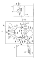
図1に示すように、シート供給装置としてのデジタル印刷装置1は、シート供給部としての給紙装置2、処理部としてのデジタル印刷ユニット3及び排出部としての排紙装置4を備える。
<Configuration of digital printing device>
As shown in FIG. 1, a digital printing apparatus 1 as a sheet supply apparatus includes a paper feeding device 2 as a sheet supply unit, a digital printing unit 3 as a processing unit, and a paper discharge device 4 as a discharge unit.

給紙装置2には、複数のシートS1が積載された積載台21および、その積載台21の最上段のシートS1をフィーダボードFBへ搬送するサッカー装置23および当該サッカー装置23と接続された間欠給紙用ロータリーバルブ27が設けられている。サッカー装置23は、第1吸23aおよび第2吸23bを備えている。   The sheet feeding device 2 includes a stacking base 21 on which a plurality of sheets S1 are stacked, a soccer device 23 that conveys the uppermost sheet S1 of the stacking base 21 to the feeder board FB, and an intermittent connection connected to the soccer device 23. A paper feed rotary valve 27 is provided. The soccer device 23 includes a first suction 23a and a second suction 23b.

フィーダボードFBのシート搬送方向先端側には、デジタル印刷ユニット3のフレーム3aに揺動自在に支持され、シートS1の一方の端部である先端(くわえ側端部)をくわえて保持する図示しないくわえ爪装置を備えたスイング装置31fが配設されている。スイング装置31fには給紙側渡し胴32が対向して配置され、その給紙側渡し胴32がフレーム3aに回転自在に支持されている。   On the front end side in the sheet conveying direction of the feeder board FB, it is supported by the frame 3a of the digital printing unit 3 so as to be swingable, and holds the front end (the end on the holding side) as one end of the sheet S1. A swing device 31f provided with a gripper device is provided. A paper feed side transfer drum 32 is disposed opposite to the swing device 31f, and the paper feed side transfer drum 32 is rotatably supported by the frame 3a.

給紙側渡し胴32には、スイング装置31fのくわえ爪装置により受け渡されるシートS1の先端をくわえた状態で保持するくわえ爪装置32aが設けられている。なおデジタル印刷ユニット3では、スイング装置31fおよび給紙側渡し胴32により上流側シート搬送装置を構成している。   The feeding side transfer cylinder 32 is provided with a gripping claw device 32a that holds the leading end of the sheet S1 delivered by the gripping claw device of the swing device 31f. In the digital printing unit 3, the swing device 31f and the sheet feeding side transfer cylinder 32 constitute an upstream sheet conveying device.

給紙側渡し胴32には、スイング装置31fよりもシート搬送方向下流側に印刷胴33が対接配置され、その印刷胴33がフレーム3aに回転自在に支持されている。印刷胴33は、給紙側渡し胴32のくわえ爪装置32aからシートS1の先端を受け取って保持する印刷胴くわえ爪装置33a、33b、33cと、この印刷胴くわえ爪装置33a、33b、33cに対応して設けられシートS1を支持する支持面33d、33e、33fとを備え、本実施の形態においては、印刷胴くわえ爪装置と支持面との組が3組設けられた3倍胴として構成されており、その直径も給紙側渡し胴32の3倍の直径を有している。ここで、シートS1を保持する印刷胴くわえ爪装置33a、33b、33cは円周方向に互いに120度位相をずらした状態で設けられている。   A printing cylinder 33 is disposed in contact with the sheet feeding side transfer cylinder 32 on the downstream side in the sheet conveying direction from the swing device 31f, and the printing cylinder 33 is rotatably supported by the frame 3a. The printing cylinder 33 includes a printing cylinder holding claw device 33a, 33b, 33c that receives and holds the leading end of the sheet S1 from the holding claw device 32a of the paper feeding side transfer cylinder 32, and the printing cylinder holding claw device 33a, 33b, 33c. Correspondingly provided support surfaces 33d, 33e, 33f for supporting the sheet S1, and in the present embodiment, a triple cylinder is provided in which three sets of the printing cylinder holding nail device and the support surface are provided. The diameter of the paper feeding side transfer cylinder 32 is three times as large. Here, the printing cylinder holding claw devices 33a, 33b, and 33c that hold the sheet S1 are provided in a state in which the phases are shifted from each other by 120 degrees in the circumferential direction.

印刷胴33の支持面33d、33e、33fには多数の複数の吸引用孔が形成されており、その複数の吸引用孔が負圧源と接続されている。この印刷胴33の給紙側渡し胴32との対接部分よりもシート搬送方向下流側には、当該印刷胴33の周面に対向して処理部としてのインクジェットノズル部34が配置されている。   A plurality of suction holes are formed in the support surfaces 33d, 33e, and 33f of the printing cylinder 33, and the plurality of suction holes are connected to a negative pressure source. An inkjet nozzle portion 34 as a processing unit is disposed opposite to the peripheral surface of the printing cylinder 33 on the downstream side in the sheet conveyance direction from the portion where the printing cylinder 33 is in contact with the sheet feeding side transfer cylinder 32. .

インクジェットノズル部34には、互いに異なる色のインキがセットされた複数のインクジェットノズルヘッド34a〜34dが印刷胴33の周面に沿ってシート搬送方向に並設され、それぞれが印刷胴33の周面を指向している。インクジェットノズルヘッド34a〜34dは、印刷胴33の支持面33d、33e、33fに全面吸着されたシートS1との隙間が僅かな間隔となるよう印刷胴33に近接して配設されている。なお、印刷胴33、インクジェットノズル部34によりシート印刷装置を構成している。   A plurality of inkjet nozzle heads 34 a to 34 d in which inks of different colors are set are arranged in the inkjet nozzle portion 34 side by side along the circumferential surface of the printing cylinder 33, and each of them is a circumferential surface of the printing cylinder 33. Is oriented. The inkjet nozzle heads 34a to 34d are arranged close to the printing cylinder 33 so that the gap between the printing nozzle 33 and the sheet S1 adsorbed on the entire surface of the supporting surface 33d, 33e, 33f is slightly spaced. The printing cylinder 33 and the inkjet nozzle unit 34 constitute a sheet printing apparatus.

印刷胴33のインクジェットノズル部34よりもシート搬送方向下流側には、印刷胴33に対接配置され、シートS1に赤外線や紫外線などの光を照射して当該シートS1上に印刷されたインキを乾燥させる乾燥装置としてのインキ乾燥ランプ35が設けられている。ここで、乾燥とは熱エネルギーを与えてインキの水分を蒸発させることやインキを硬化させることを含むものであり、固化と言い換えることができる。   An ink printed on the sheet S1 by irradiating the sheet S1 with light such as infrared rays or ultraviolet rays is disposed on the downstream side of the printing cylinder 33 in the sheet conveyance direction with respect to the inkjet nozzle portion 34, and is irradiated with light such as infrared rays or ultraviolet rays. An ink drying lamp 35 is provided as a drying device for drying. Here, the term “drying” includes evaporation of moisture of the ink by applying thermal energy and curing of the ink, which can be called solidification.

印刷胴33には、インクジェットノズル部34よりもシート搬送方向下流側に、第1の排紙側渡し胴36が対接配置され、その第1の排紙側渡し胴36がフレーム3aに回転自在に支持されている。第1の排紙側渡し胴36には、印刷胴33により搬送されるシートS1の先端を印刷胴くわえ爪装置33a、33b、33cから受け取って保持するくわえ爪装置36aが設けられている。   A first paper discharge side transfer cylinder 36 is disposed in contact with the printing cylinder 33 on the downstream side in the sheet conveying direction from the ink jet nozzle portion 34, and the first paper discharge side transfer cylinder 36 is rotatable to the frame 3a. It is supported by. The first paper discharge side transfer cylinder 36 is provided with a gripping claw device 36a that receives and holds the leading end of the sheet S1 conveyed by the printing cylinder 33 from the printing cylinder gripping claw devices 33a, 33b, and 33c.

第1の排紙側渡し胴36の印刷胴33との対接部分よりもシート搬送方向下流側には、第2の排紙側渡し胴37が第1の排紙側渡し胴36と対接配置され、その第2の排紙側渡し胴37がフレーム3aに回転自在に支持されている。第2の排紙側渡し胴37には、第1の排紙側渡し胴36により搬送されるシートS1の先端を受け取って保持するくわえ爪装置37aが設けられている。   A second paper discharge side transfer cylinder 37 is in contact with the first paper discharge side transfer cylinder 36 on the downstream side of the first paper discharge side transfer cylinder 36 in contact with the printing cylinder 33 in the sheet conveying direction. The second paper discharge side transfer cylinder 37 is rotatably supported by the frame 3a. The second paper discharge side transfer drum 37 is provided with a gripping claw device 37a for receiving and holding the leading edge of the sheet S1 conveyed by the first paper discharge side transfer drum 36.

第2の排紙側渡し胴37の第1の排紙側渡し胴36との対接部分よりもシート搬送方向下流側には紙取胴38が対接配置され、その紙取胴38がフレーム3aに回転自在に支持されている。紙取胴38には、第2の排紙側渡し胴37により搬送されるシートS1の先端を受け取って保持するくわえ爪装置38aが設けられている。   A paper take-up cylinder 38 is disposed in contact with the first paper discharge-side transfer cylinder 37 on the downstream side of the second paper discharge-side transfer cylinder 37 with respect to the first paper discharge-side transfer cylinder 36. 3a is rotatably supported. The paper take-up cylinder 38 is provided with a gripping claw device 38a that receives and holds the leading end of the sheet S1 conveyed by the second paper discharge side transfer cylinder 37.

紙取胴38の下方には、シートS1を搬送するベルトコンベア状のデリバリーベルト40が配設されている。デリバリーベルト40のシート搬送方向先端側には、デジタル印刷ユニット3によりデジタル印刷処理の施されたシートS1を積載する積載台41が設けられている。なお、紙取胴38、デリバリーベルト40、積載台41により排紙装置4を構成し、紙取胴38およびデリバリーベルト40により搬送されるシートS1の経路がシート排出経路を構成する。   Below the paper drum 38, a belt-conveyor-like delivery belt 40 that conveys the sheet S1 is disposed. On the leading end side of the delivery belt 40 in the sheet conveyance direction, a stacking base 41 on which the sheet S1 subjected to digital printing processing by the digital printing unit 3 is stacked is provided. The paper take-up cylinder 38, the delivery belt 40, and the stacking base 41 constitute the paper discharge device 4, and the path of the sheet S1 conveyed by the paper take-up cylinder 38 and the delivery belt 40 constitutes the sheet discharge path.

第2の排紙側渡し胴37の紙取胴38との対接部分よりもシート搬送方向下流側には、反転前倍胴39が対接配置され、その反転前倍胴39がフレーム3aに回転自在に支持されている。反転前倍胴39は、第2の排紙側渡し胴37の2倍の直径を有する2倍胴であり、第2の排紙側渡し胴37により搬送されるシートS1の先端を受け取って保持するくわえ爪装置39aが設けられている。   A pre-reverse double cylinder 39 is disposed in contact with the paper discharge cylinder 38 on the downstream side of the second paper discharge side transfer cylinder 37 and the paper take-up cylinder 38. The pre-reverse double cylinder 39 is disposed on the frame 3a. It is supported rotatably. The pre-inversion double cylinder 39 is a double cylinder having a diameter twice that of the second paper discharge side transfer cylinder 37, and receives and holds the leading end of the sheet S1 conveyed by the second paper discharge side transfer cylinder 37. A holding claw device 39a is provided.

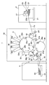
反転前倍胴39の第2の排紙側渡し胴37との対接部分よりもシート搬送方向下流側には、図2に示されるように、シートS1の他方の端部としての後端(尻側端部)を受け取って保持するくわえ爪装置31btを備えた反転スイング装置31bが対向して配置されている。なお、反転前倍胴39および反転スイング装置31bによりシートS1の表裏を反転させて印刷胴33へ受け渡すシート反転部を構成する。   As shown in FIG. 2, as shown in FIG. 2, the rear end (the other end portion of the sheet S <b> 1) is located downstream of the contact portion of the pre-reverse double cylinder 39 with the second discharge-side transfer cylinder 37. A reversing swing device 31b provided with a gripper device 31bt for receiving and holding the (butt side end) is disposed oppositely. In addition, a sheet reversing unit configured to reverse the front and back of the sheet S1 by the pre-reversing double cylinder 39 and the reversing swing device 31b and deliver it to the printing cylinder 33 is configured.

ところで図3に示すように、給紙装置2は、サッカー装置23、間欠供給用ロータリーバルブとしての間欠給紙用ロータリーバルブ27、負圧源25aおよび正圧源25bを有し、負圧源25aと間欠給紙用ロータリーバルブ27との間に三方弁24aが配設されるとともに正圧源25bと間欠給紙用ロータリーバルブ27との間に三方弁24bが配設され、さらに間欠給紙用ロータリーバルブ27とサッカー装置23との間に連続供給用負圧ロータリーバルブとしての連続給紙用負圧ロータリーバルブ26aおよび連続供給用正圧ロータリーバルブとしての連続給紙用正圧ロータリーバルブ26bが並設されている。間欠給紙用ロータリーバルブ27、連続給紙用負圧ロータリーバルブ26aおよび連続給紙用正圧ロータリーバルブ26bは、それぞれ専用のモータによりバルブの開閉が駆動される。   As shown in FIG. 3, the paper feeding device 2 includes a soccer device 23, an intermittent paper feeding rotary valve 27 as an intermittent feeding rotary valve, a negative pressure source 25a, and a positive pressure source 25b, and a negative pressure source 25a. Between the positive pressure source 25b and the intermittent feed rotary valve 27, and further for intermittent feed. Between the rotary valve 27 and the soccer device 23, a negative pressure rotary valve 26a for continuous feeding as a negative pressure rotary valve for continuous supply and a positive pressure rotary valve 26b for continuous feeding as a positive pressure rotary valve for continuous supply are arranged. It is installed. The intermittent feed rotary valve 27, the continuous feed negative pressure rotary valve 26a, and the continuous feed positive pressure rotary valve 26b are each driven to open and close by a dedicated motor.

負圧源25aと三方弁24aとは、負圧管28aを介して接続されている。三方弁24aと連続給紙用負圧ロータリーバルブ26aとは、負圧管28b及び負圧管28dを介して接続されると共に、三方弁24aと間欠給紙用ロータリーバルブ27とは負圧管28cを介して接続されている。間欠給紙用ロータリーバルブ27と連続給紙用負圧ロータリーバルブ26aとは負圧管28dを介して接続され、連続給紙用負圧ロータリーバルブ26aとサッカー装置23とは負圧管28eを介して接続されている。なお、負圧管28bの一方の端部が負圧管28dと結合され、三方弁24aと連続給紙用負圧ロータリーバルブ26aとの間に負圧用流路が形成されている。三方弁24aおよび間欠給紙用ロータリーバルブ27は負圧源25aからのサッカー装置23に対する負圧の作用のオンオフを切り換える切換手段としての負圧切換手段を構成している。   The negative pressure source 25a and the three-way valve 24a are connected via a negative pressure pipe 28a. The three-way valve 24a and the continuous feeding negative pressure rotary valve 26a are connected via a negative pressure pipe 28b and a negative pressure pipe 28d. The three-way valve 24a and the intermittent feeding rotary valve 27 are connected via a negative pressure pipe 28c. It is connected. The intermittent feeding rotary valve 27 and the continuous feeding negative pressure rotary valve 26a are connected via a negative pressure pipe 28d, and the continuous feeding negative pressure rotary valve 26a and the soccer device 23 are connected via a negative pressure pipe 28e. Has been. Note that one end of the negative pressure pipe 28b is coupled to the negative pressure pipe 28d, and a negative pressure flow path is formed between the three-way valve 24a and the continuous feeding negative pressure rotary valve 26a. The three-way valve 24a and the intermittent feed rotary valve 27 constitute negative pressure switching means as switching means for switching on / off the action of negative pressure on the soccer device 23 from the negative pressure source 25a.

三方弁24aは、負圧管28c側を閉じると共に負圧管28b側を開いて間欠給紙用ロータリーバルブ27を介さずに負圧源25aとサッカー装置23とを接続する連続給紙用接続(第1の接続状態)と、負圧管28c側を開くと共に負圧管28b側を閉じて間欠給紙用ロータリーバルブ27を介して負圧源25aとサッカー装置23とを接続する間欠給紙用接続(第2の接続状態)とに接続状態を切り換えることができる。   The three-way valve 24a closes the negative pressure pipe 28c side and opens the negative pressure pipe 28b side to connect the negative pressure source 25a and the soccer device 23 without the intermittent feed rotary valve 27 (first feed). Connection state), and the negative pressure pipe 28c side is opened and the negative pressure pipe 28b side is closed and the negative pressure source 25a and the soccer device 23 are connected via the intermittent feed rotary valve 27 (second connection). Connection state).

正圧源25bと三方弁24bとは、正圧管29aを介して接続されている。三方弁24bと連続給紙用正圧ロータリーバルブ26bとは、正圧管29b及び正圧管29dを介して接続されると共に、三方弁24bと間欠給紙用ロータリーバルブ27とは正圧管29cを介して接続されている。間欠給紙用ロータリーバルブ27と連続給紙用正圧ロータリーバルブ26bとは正圧管29dを介して接続され、連続給紙用正圧ロータリーバルブ26bとサッカー装置23とは正圧管29eを介して接続されている。なお、正圧管29bの一方の端部が正圧管29dと結合され、三方弁24bと連続給紙用正圧ロータリーバルブ26bとの間に正圧用流路が形成されている。三方弁24bおよび間欠給紙用ロータリーバルブ27は正圧源25bからのサッカー装置23に対する正圧の作用のオンオフを切り換える切換手段としての正圧切換手段を構成している。   The positive pressure source 25b and the three-way valve 24b are connected via a positive pressure pipe 29a. The three-way valve 24b and the continuous feed positive pressure rotary valve 26b are connected via a positive pressure pipe 29b and a positive pressure pipe 29d, and the three-way valve 24b and the intermittent feed rotary valve 27 are connected via a positive pressure pipe 29c. It is connected. The intermittent feeding rotary valve 27 and the continuous feeding positive pressure rotary valve 26b are connected via a positive pressure pipe 29d, and the continuous feeding positive pressure rotary valve 26b and the soccer device 23 are connected via a positive pressure pipe 29e. Has been. One end of the positive pressure pipe 29b is coupled to the positive pressure pipe 29d, and a positive pressure flow path is formed between the three-way valve 24b and the continuous feed positive pressure rotary valve 26b. The three-way valve 24b and the intermittent paper feeding rotary valve 27 constitute positive pressure switching means as switching means for switching on / off the action of positive pressure on the soccer device 23 from the positive pressure source 25b.

三方弁24bは、正圧管29c側を閉じると共に正圧管29b側を開いて間欠給紙用ロータリーバルブ27を介さずに正圧源25bとサッカー装置23とを接続する連続給紙用接続(第1の接続状態)と、正圧管29c側を開くと共に正圧管29b側を閉じて間欠給紙用ロータリーバルブ27を介して正圧源25bとサッカー装置23とを接続する間欠給紙用接続(第2の接続状態)とに接続状態を切り換えることができる。   The three-way valve 24b closes the positive pressure pipe 29c side and opens the positive pressure pipe 29b side to connect the positive pressure source 25b and the soccer device 23 without the intermittent feed rotary valve 27 (first feed). ), And the positive pressure tube 29c side is opened and the positive pressure tube 29b side is closed and the positive pressure source 25b and the soccer device 23 are connected via the intermittent feed rotary valve 27 (second connection). Connection state).

<制御系の構成>
次に、デジタル印刷装置1の制御系の構成について説明する。図4に示すように、CPU(Central Processing Unit)によって構成される制御装置100には、片面印刷モードまたは両面印刷モードを選択する印刷モード選択スイッチ101と、位相検出器としてのロータリエンコーダ103とが接続されるとともに、間欠給紙用ロータリーバルブ27、三方弁24a、24bおよび連続給紙用負圧ロータリーバルブ26a、連続給紙用正圧ロータリーバルブ26bが接続されている。
<Control system configuration>
Next, the configuration of the control system of the digital printing apparatus 1 will be described. As shown in FIG. 4, a control device 100 constituted by a CPU (Central Processing Unit) includes a print mode selection switch 101 that selects a single-sided printing mode or a double-sided printing mode, and a rotary encoder 103 as a phase detector. In addition to the connection, the intermittent feed rotary valve 27, the three-way valves 24a and 24b, the continuous feed negative pressure rotary valve 26a, and the continuous feed positive pressure rotary valve 26b are connected.

<デジタル印刷装置の印刷動作>
このように構成されたデジタル印刷装置1の印刷動作について、片面印刷モードが選択された場合と、両面印刷モードが選択された場合とに分けて説明する。
<Printing operation of digital printing device>
The printing operation of the digital printing apparatus 1 configured as described above will be described separately when the single-sided printing mode is selected and when the double-sided printing mode is selected.

<片面印刷モードの印刷動作>
デジタル印刷装置1の運転に先立ち、作業者が印刷モード選択スイッチ101を操作して片面印刷モードを選択する。制御装置100は、印刷モード選択スイッチ101を介して片面印刷モードが選択されたことを認識すると、負圧管28c側を閉じると共に負圧管28b側を開くように三方弁24aを制御するとともに、正圧管29c側を閉じると共に正圧管29b側を開くように三方弁24bを制御する。
<Printing operation in single-sided printing mode>
Prior to the operation of the digital printing apparatus 1, the operator operates the print mode selection switch 101 to select the single-sided print mode. When recognizing that the single-sided printing mode is selected via the printing mode selection switch 101, the control device 100 controls the three-way valve 24a so as to close the negative pressure pipe 28c side and open the negative pressure pipe 28b side. The three-way valve 24b is controlled so as to close the 29c side and open the positive pressure pipe 29b side.

三方弁24aが負圧管28c側を閉じると共に負圧管28b側を開くと、負圧管28a、三方弁24a、負圧管28b、負圧管28d、連続給紙用負圧ロータリーバルブ26aおよび負圧管28eを介して、シートS1の連続給紙時に負圧源25aからの負圧をサッカー装置23の第1吸23aおよび第2吸23bに作用させる連続給紙用負圧流路が形成される。   When the three-way valve 24a closes the negative pressure pipe 28c side and opens the negative pressure pipe 28b side, the negative pressure pipe 28a, the three-way valve 24a, the negative pressure pipe 28b, the negative pressure pipe 28d, the negative pressure rotary valve 26a for continuous feeding, and the negative pressure pipe 28e are passed through. Thus, a continuous feed negative pressure flow path is formed in which the negative pressure from the negative pressure source 25a is applied to the first suction 23a and the second suction 23b of the soccer device 23 during continuous feeding of the sheet S1.

三方弁24bが正圧管29c側を閉じると共に正圧管29b側を開くと、正圧管29a、三方弁24b、正圧管29b、正圧管29d、連続給紙用正圧ロータリーバルブ26bおよび正圧管29eを介して、シートS1の連続給紙時に正圧源25bからの正圧をサッカー装置23の第1吸23aおよび第2吸23bに作用させる連続給紙用正圧流路が形成される。   When the three-way valve 24b closes the positive pressure pipe 29c side and opens the positive pressure pipe 29b side, the positive pressure pipe 29a, the three-way valve 24b, the positive pressure pipe 29b, the positive pressure pipe 29d, the continuous feeding positive pressure rotary valve 26b and the positive pressure pipe 29e are passed through. Thus, a positive pressure flow path for continuous sheet feeding is formed in which the positive pressure from the positive pressure source 25b is applied to the first suction 23a and the second suction 23b of the soccer device 23 when the sheet S1 is continuously fed.

このように三方弁24a、24bにより、負圧源25aおよび正圧源25bとサッカー装置23とは、間欠給紙用ロータリーバルブ27を介さないで接続される第1の接続状態に切り換えられる。   In this way, the three-way valves 24a and 24b switch the negative pressure source 25a and the positive pressure source 25b to the soccer device 23 to the first connection state in which they are connected without the intermittent feeding rotary valve 27.

図5に示すように、制御装置100は、印刷胴33の1回転中に当該印刷胴33に設けられた印刷胴くわえ爪装置33a、33b、33cの数と同じ枚数のシートS1を供給するタイミング、換言すると、印刷胴33における各くわえ爪装置33a、33b、33cと給紙側渡し胴32のくわえ爪装置32aとが対向するタイミング(周期)ごとに第1吸23aおよび第2吸23bの負圧源25からの吸引が行なわれるように、ロータリエンコーダ103からの検出信号(機械位相および機械速度の検出値)に基づいて連続給紙用負圧ロータリーバルブ26aの開閉を制御する。このように、印刷胴33の全ての印刷胴くわえ爪装置33a、33b、33cがシートS1をくわえるように当該シートS1を供給することを連続給紙(連続供給)と呼び、連続給紙における連続給紙用負圧ロータリーバルブ26aの開閉周期を第1の周期と呼ぶ。   As shown in FIG. 5, the control apparatus 100 supplies the same number of sheets S1 as the number of the printing cylinder holding nail devices 33a, 33b, 33c provided in the printing cylinder 33 during one rotation of the printing cylinder 33. In other words, the negative of the first suction 23a and the second suction 23b at each timing (cycle) at which the gripping claw devices 33a, 33b, 33c in the printing cylinder 33 and the gripping claw device 32a of the feeding-side transfer cylinder 32 face each other. The opening / closing of the negative pressure rotary valve 26a for continuous feeding is controlled based on detection signals (detected values of the mechanical phase and the mechanical speed) from the rotary encoder 103 so that suction from the pressure source 25 is performed. In this way, supplying the sheet S1 so that all the printing cylinder holding claw devices 33a, 33b, and 33c of the printing cylinder 33 hold the sheet S1 is called continuous feeding (continuous feeding), and continuous feeding in continuous feeding. The opening / closing cycle of the negative pressure rotary valve 26a for feeding is referred to as a first cycle.

給紙装置2の第1吸23aおよび第2吸23bは、シートS1をフィーダボードFBへ送り出す送給動作を第1の周期で周期的に行っており、連続給紙用負圧ロータリーバルブ26aおよび連続給紙用正圧ロータリーバルブ26bの第1の周期での開閉動作との組合せにより積載台21のシートS1を第1の周期でフィーダボードFBへ供給するのである。   The first suction 23a and the second suction 23b of the sheet feeding device 2 periodically perform the feeding operation of feeding the sheet S1 to the feeder board FB in the first cycle, and the negative pressure rotary valve 26a for continuous feeding and The sheet S1 of the stacking table 21 is supplied to the feeder board FB in the first cycle by the combination with the opening / closing operation in the first cycle of the continuous pressure positive pressure rotary valve 26b.

すなわち、連続給紙用負圧ロータリーバルブ26aが「開」状態の区間(t1〜t2、t3〜t4、t5〜t6、t7〜t8、…、)では、サッカー装置23の第1吸23aおよび第2吸23bによりシートS1を吸着した状態でフィーダボードFBまで搬送し、連続給紙用負圧ロータリーバルブ26aが「閉」状態の区間(t2〜t3、t4〜t5、t6〜t7、t8〜t9、…、)では、サッカー装置23がフィーダボードFBから積載台21へ戻る。   That is, in the section (t1 to t2, t3 to t4, t5 to t6, t7 to t8,...) In which the negative pressure rotary valve 26a for continuous feeding is in the “open” state, the first suction 23a and the first suction 23a of the soccer device 23. The sheet S1 is sucked by the two suctions 23b and conveyed to the feeder board FB, and the continuous feeding negative pressure rotary valve 26a is in the “closed” state (t2 to t3, t4 to t5, t6 to t7, t8 to t9). ,..., The soccer device 23 returns from the feeder board FB to the loading platform 21.

時点t1のタイミングにおいて連続給紙用負圧ロータリーバルブ26aが「開」状態になると、負圧源25aとサッカー装置23とが三方弁24aを介して連通するため、負圧源25aからの負圧作用により第1吸23aおよび第2吸23bが積載台21のシートS1を吸着する。第1吸23aおよび第2吸23bにより吸着されたシートS1が時点t1〜時点t2の区間でフィーダボードFBへ搬送された後、時点t2のタイミングで連続給紙用負圧ロータリーバルブ26aが「閉」状態となるためシートS1に対する負圧源25aからの負圧作用が解除される。   When the negative pressure rotary valve 26a for continuous feeding is in an “open” state at the timing of the time point t1, the negative pressure source 25a and the soccer device 23 communicate with each other via the three-way valve 24a, and therefore the negative pressure from the negative pressure source 25a. By the action, the first suction 23a and the second suction 23b suck the sheet S1 on the stack 21. After the sheet S1 adsorbed by the first suction 23a and the second suction 23b is conveyed to the feeder board FB in the section from the time point t1 to the time point t2, the negative pressure rotary valve 26a for continuous feeding is closed at the timing of the time point t2. Therefore, the negative pressure action from the negative pressure source 25a on the sheet S1 is released.

時点t2のタイミングで連続給紙用負圧ロータリーバルブ26aが「閉」状態となり、負圧源25aからの負圧作用が解除されると同時に、制御装置100は、一時的に連続給紙用正圧ロータリーバルブ26bを「開」状態とする。これにより、連続給紙用正圧ロータリーバルブ26bが一時的に開くので、サッカー装置23の第1吸23aおよび第2吸23bに吸着されたシートS1に対して正圧源25bからの正圧を作用させる。   At the timing of time t2, the negative pressure rotary valve 26a for continuous paper feeding is in a “closed” state, and the negative pressure action from the negative pressure source 25a is released. The pressure rotary valve 26b is set to the “open” state. As a result, the continuous feeding positive pressure rotary valve 26b is temporarily opened, so that the positive pressure from the positive pressure source 25b is applied to the sheet S1 adsorbed by the first suction 23a and the second suction 23b of the soccer device 23. Make it work.

かくして、正圧源25bからの正圧作用によりシートS1が第1吸23aおよび第2吸23bによる吸着から確実に解放され、当該シートS1がフィーダボードFB上に送給される。   Thus, the sheet S1 is reliably released from the suction by the first suction 23a and the second suction 23b by the positive pressure action from the positive pressure source 25b, and the sheet S1 is fed onto the feeder board FB.

上述した時点t1〜時点t3の区間におけるシートS1のフィーダボードFBへの給送は、他の時点における区間t3〜t4、t5〜t6、t7〜t8、…、においても同様に実施され、シートS1の連続供給が実施される。なお、連続給紙用正圧ロータリーバルブ26bが「開」状態となるのは、連続給紙用負圧ロータリーバルブ26aが「閉」状態となるタイミングであり、その周期は第1の周期と同じである。   The feeding of the sheet S1 to the feeder board FB in the section from the time point t1 to the time point t3 described above is similarly performed in the sections t3 to t4, t5 to t6, t7 to t8,. Is continuously supplied. The continuous feeding positive pressure rotary valve 26b is in the “open” state at the timing when the continuous feeding negative pressure rotary valve 26a is in the “closed” state, and the cycle is the same as the first cycle. It is.

フィーダボードFBにより搬送されるシートS1は、その先端がスイング装置31fのくわえ爪装置によって保持された後に当該スイング装置31fの揺動により給紙側渡し胴32へ向かって搬送され、その給紙側渡し胴32のくわえ爪装置32aに当該シートS1の先端がくわえ替えされる。   The sheet S1 conveyed by the feeder board FB is conveyed toward the sheet feeding side transfer cylinder 32 by the swing of the swing device 31f after the leading end is held by the gripping claw device of the swing device 31f. The leading end of the sheet S1 is replaced by the holding claw device 32a of the transfer cylinder 32.

フィーダボードFBにより搬送されるシートS1はその先端がスイング装置31fのくわえ爪装置によって保持された後に給紙側渡し胴32へ向かって揺動して搬送され、その給紙側渡し胴32のくわえ爪装置32aに当該シートS1の先端がくわえ替えされる。   The sheet S1 conveyed by the feeder board FB is held by the gripping claw device of the swing device 31f and then oscillated toward the sheet feeding side transfer cylinder 32. The sheet S1 is held by the sheet feeding side transfer cylinder 32. The leading end of the sheet S1 is replaced by the nail device 32a.

給紙側渡し胴32の回転に伴って搬送されるシートS1は、印刷胴33との対接部分において給紙側渡し胴32のくわえ爪装置32aから印刷胴33の印刷胴くわえ爪装置33a〜33cの何れかにその先端がくわえ替えされた後、印刷胴33の回転とともに搬送される。このときシートS1の全面は、印刷胴33における複数の吸引用孔を介して当該印刷胴33の支持面33d〜33fに吸着されて当該支持面33d〜33fに密着する。   The sheet S1 conveyed along with the rotation of the sheet feeding side transfer cylinder 32 is transferred from the gripping claw device 32a of the sheet feeding side transfer cylinder 32 to the printing cylinder holding claw device 33a to 33a of the printing cylinder 33 at the contact portion with the printing cylinder 33. After the tip is replaced by any of 33c, it is conveyed along with the rotation of the printing cylinder 33. At this time, the entire surface of the sheet S1 is adsorbed to the support surfaces 33d to 33f of the printing cylinder 33 through the plurality of suction holes in the printing cylinder 33 and closely contacts the support surfaces 33d to 33f.

印刷胴33により搬送されるシートS1の表面には、インクジェットノズル部34のインクジェットノズルヘッド34a〜34dから微滴化されたインクが吐出されることによりデジタル印刷処理が施される。シートS1は印刷胴33の支持面33d〜33fに密着しているため、インクジェットノズルヘッド34a〜34dとの間の微小間隔が維持された状態で搬送される。この微小間隔が維持されることにより吐出されたインクがシートS1に高精度で着弾することができ、高品質な印刷を行うことができる。   Digital printing processing is performed on the surface of the sheet S <b> 1 conveyed by the printing cylinder 33 by ejecting fine droplets of ink from the inkjet nozzle heads 34 a to 34 d of the inkjet nozzle portion 34. Since the sheet S <b> 1 is in close contact with the support surfaces 33 d to 33 f of the printing cylinder 33, the sheet S <b> 1 is conveyed in a state where a minute gap between the ink jet nozzle heads 34 a to 34 d is maintained. By maintaining this minute interval, the ejected ink can land on the sheet S1 with high accuracy, and high-quality printing can be performed.

インクジェットノズル部34による印刷が行われたシートS1は、印刷胴33とインキ乾燥ランプ35との間を通過し、当該インキ乾燥ランプ35からの光が照射され、これによりシートS1のインキが乾燥する。その後シートS1は第1の排紙側渡し胴36へ搬送される。   The sheet S1 that has been printed by the inkjet nozzle unit 34 passes between the printing cylinder 33 and the ink drying lamp 35, and is irradiated with light from the ink drying lamp 35, whereby the ink on the sheet S1 is dried. . Thereafter, the sheet S1 is conveyed to the first paper discharge side transfer cylinder 36.

図6に示すように、印刷胴33と第1の排紙側渡し胴36との対接部分において印刷胴33の印刷胴くわえ爪装置33a〜33cから第1の排紙側渡し胴36のくわえ爪装置36aにシートS1の先端がくわえ替えされる。その後、図7に示すように、第1の排紙側渡し胴36のくわえ爪装置36aに保持されたシートS1は、第1の排紙側渡し胴36と第2の排紙側渡し胴37との対接部分において、第1の排紙側渡し胴36のくわえ爪装置36aから第2の排紙側渡し胴37のくわえ爪装置37aにその先端がくわえ替えされる。   As shown in FIG. 6, in the contact portion between the printing cylinder 33 and the first paper discharge side transfer cylinder 36, the print cylinder holding nail devices 33 a to 33 c of the printing cylinder 33 hold the first paper discharge side transfer cylinder 36. The leading end of the sheet S1 is replaced with the nail device 36a. Thereafter, as shown in FIG. 7, the sheet S <b> 1 held by the gripping claw device 36 a of the first paper discharge side transfer drum 36 is transferred to the first paper discharge side transfer drum 36 and the second paper discharge side transfer drum 37. At the contact portion, the gripper claw device 36a of the first paper discharge side transfer drum 36 is replaced with the gripper claw device 37a of the second paper discharge side transfer drum 37.

片面印刷モードの場合、第2の排紙側渡し胴37と紙取胴38との対接部分において、第2の排紙側渡し胴37のくわえ爪装置37aがシートS1の先端の保持を解除するとともに、紙取胴38のくわえ爪装置38aがシートS1の先端をくわえて保持し、くわえ替えが行なわれる。これによりシートS1は第2の排紙側渡し胴37から紙取胴38へくわえ替えされて搬送される。   In the single-sided printing mode, the holding claw device 37a of the second discharge side transfer cylinder 37 releases the holding of the leading edge of the sheet S1 at the contact portion between the second discharge side transfer cylinder 37 and the paper take-up cylinder 38. At the same time, the holding claw device 38a of the paper take-up cylinder 38 holds the leading end of the sheet S1, and the holding is changed. As a result, the sheet S1 is transferred from the second delivery side transfer cylinder 37 to the paper take-up cylinder 38 and conveyed.

紙取胴38にくわえ替えされたシートS1は、デリバリーベルト40の上方に紙取胴38のくわえ爪装置38aが位置したタイミングで当該くわえ爪装置38aによる保持が解除され、デリバリーベルト40上に載せられる。   The sheet S1 that has been replaced by the paper take-up cylinder 38 is released from being held by the holding claw device 38a at the timing when the holding claw device 38a of the paper take-up cylinder 38 is positioned above the delivery belt 40 and placed on the delivery belt 40. It is done.

デリバリーベルト40上に載せられたシートS1は当該デリバリーベルト40の走行とともに搬送され、表面にデジタル印刷処理の施されたシートS1が積載台41上に排出される。   The sheet S1 placed on the delivery belt 40 is conveyed along with the travel of the delivery belt 40, and the sheet S1 whose surface is subjected to digital printing processing is discharged onto the stacking table 41.

<両面印刷モードの印刷動作>
一方、制御装置100は、作業者が印刷モード選択スイッチ101を介して両面印刷モードを選択したことを認識すると、負圧管28b側を閉じると共に負圧管28c側を開くように三方弁24aを制御するとともに、正圧管29b側を閉じると共に正圧管29c側を開くように三方弁24bを制御する。
<Printing operation in duplex printing mode>
On the other hand, when the control device 100 recognizes that the operator has selected the duplex printing mode via the print mode selection switch 101, the control device 100 controls the three-way valve 24a so as to close the negative pressure pipe 28b side and open the negative pressure pipe 28c side. At the same time, the three-way valve 24b is controlled so that the positive pressure pipe 29b side is closed and the positive pressure pipe 29c side is opened.

三方弁24aが負圧管28b側を閉じると共に負圧管28c側を開くと、負圧管28a、三方弁24a、負圧管28c、間欠給紙用ロータリーバルブ27、負圧管28d、連続給紙用負圧ロータリーバルブ26aおよび負圧管28eを介して、シートS1の間欠給紙時に負圧源25aからの負圧をサッカー装置23の第1吸23aおよび第2吸23bに一つおきに作用させる間欠給紙用負圧流路が形成される。   When the three-way valve 24a closes the negative pressure pipe 28b side and opens the negative pressure pipe 28c side, the negative pressure pipe 28a, the three-way valve 24a, the negative pressure pipe 28c, the intermittent feeding rotary valve 27, the negative pressure pipe 28d, and the continuous feeding negative pressure rotary For intermittent sheet feeding, the negative pressure from the negative pressure source 25a is applied to the first suction 23a and the second suction 23b of the soccer device 23 every other time via the valve 26a and the negative pressure pipe 28e when the sheet S1 is intermittently fed. A negative pressure channel is formed.

三方弁24bが正圧管29b側を閉じると共に正圧管29c側を開くと、正圧管29a、三方弁24b、正圧管29c、間欠給紙用ロータリバルブ27、正圧管29d、連続給紙用正圧ロータリーバルブ26bおよび正圧管29eを介して、シートS1の連続給紙時に正圧源25bからの正圧をサッカー装置23の第1吸23aおよび第2吸23bに一つおきに作用させる間欠給紙用正圧流路が形成される。   When the three-way valve 24b closes the positive pressure pipe 29b side and opens the positive pressure pipe 29c side, the positive pressure pipe 29a, the three-way valve 24b, the positive pressure pipe 29c, the intermittent feed rotary valve 27, the positive pressure pipe 29d, and the continuous feed positive pressure rotary For intermittent sheet feeding, the positive pressure from the positive pressure source 25b is applied to the first suction 23a and the second suction 23b of the soccer device 23 every other time via the valve 26b and the positive pressure pipe 29e during continuous sheet feeding. A positive pressure flow path is formed.

このように三方弁24a、24bにより、負圧源25aおよび正圧源25bとサッカー装置23とは、間欠給紙用ロータリーバルブ27を介して接続される第2の接続状態に切り換えられる。   In this way, the three-way valves 24a and 24b switch the negative pressure source 25a and the positive pressure source 25b to the soccer device 23 to the second connection state in which they are connected via the intermittent feed rotary valve 27.

図8に示すように、制御装置100は、連続給紙の場合と同じタイミング、すなわち、印刷胴33における印刷胴くわえ爪装置33a乃至33cと、給紙側渡し胴32のくわえ爪装置32aとが対向するタイミング(第1の周期)で、バルブが「開」、「開」、「開」、「開」、…、となるようにロータリエンコーダ103からの検出信号(機械位相および機械速度の検出値)に基づいて連続給紙用負圧ロータリーバルブ26aの開閉を制御するとともに、連続給紙のタイミングに対して一つおきのタイミングでシートS1を供給するタイミング、すなわち連続給紙用負圧ロータリーバルブ26aの1周期(区間t1〜t3、t3〜t5、t5〜t7、t7〜t9、…、)ごとに間欠給紙用ロータリーバルブ27のバルブが「開」、「閉」、「開」、「閉」、…、となるようにロータリエンコーダ103からの検出信号(機械位相および機械速度の検出値)に基づいて当該間欠給紙用ロータリーバルブ27の開閉を制御する。つまり間欠給紙用ロータリーバルブ27の開閉周期(区間t1〜t5、t5〜t9、…、)は、連続給紙用負圧ロータリーバルブ26aの2倍の周期である。   As shown in FIG. 8, the control device 100 has the same timing as in the case of continuous feeding, that is, the printing cylinder holding claw devices 33 a to 33 c in the printing cylinder 33 and the holding claw device 32 a in the feeding side transfer cylinder 32. Detection signals (detection of machine phase and machine speed) from the rotary encoder 103 so that the valves become “open”, “open”, “open”, “open”,... At the opposite timing (first period). Value) is controlled to open and close the negative pressure rotary valve 26a for continuous feeding, and the timing at which the sheet S1 is supplied at every other timing with respect to the timing of continuous feeding, that is, the negative pressure rotary for continuous feeding. The valve of the intermittent sheet feeding rotary valve 27 is “open”, “closed” for each cycle (sections t1 to t3, t3 to t5, t5 to t7, t7 to t9,...) Of the valve 26a. Open "," closed ", ..., and controls the opening and closing of the rotary valve 27 for the intermittent feeding on the basis of a detection signal from the rotary encoder 103 (detection value of the mechanical phase and machine speed) so. That is, the open / close cycle of the intermittent feed rotary valve 27 (sections t1 to t5, t5 to t9,...) Is twice the cycle of the continuous feed negative pressure rotary valve 26a.

このように、印刷胴33の印刷胴くわえ爪装置33a、33b、33cが一つおきにシートS1をくわえるように当該シートS1を供給することを間欠給紙(間欠供給)と呼び、間欠給紙における間欠給紙用ロータリーバルブ27の開閉周期を第2の周期と呼ぶ。   In this way, supplying the sheet S1 so that the printing cylinder holding claw devices 33a, 33b, and 33c of the printing cylinder 33 hold the sheet S1 every other time is called intermittent sheet feeding (intermittent feeding), and intermittent sheet feeding is performed. The opening / closing cycle of the intermittent sheet feeding rotary valve 27 is referred to as a second cycle.

間欠給紙の場合、給紙装置2の第1吸23aおよび第2吸23bが第1の周期でシートS1をフィーダーボードFBへ送り出す搬送動作を行い、かつ連続給紙用負圧ロータリーバルブ26aおよび連続給紙用正圧ロータリーバルブ26bも第1の周期で開閉動作を行なうが、間欠給紙用ロータリーバルブ27が第2の周期で開閉するので、第1吸23aおよび第2吸23bには第2の周期で負圧および正圧が作用するのである。   In the case of intermittent sheet feeding, the first suction 23a and the second suction 23b of the sheet feeding device 2 perform a conveying operation of sending the sheet S1 to the feeder board FB in the first cycle, and the negative pressure rotary valve 26a for continuous feeding and The continuous feed positive pressure rotary valve 26b also opens and closes in the first cycle. However, since the intermittent feed rotary valve 27 opens and closes in the second cycle, the first suction 23a and the second suction 23b have a second opening and closing operation. A negative pressure and a positive pressure act in two cycles.

具体的には、図8に示されるように、時点t1〜時点t3の区間、時点t5〜時点t7の区間において間欠給紙用ロータリーバルブ27が「開」状態となるように制御される。   Specifically, as shown in FIG. 8, the intermittent sheet feeding rotary valve 27 is controlled to be in the “open” state in the section from time t1 to time t3 and in the section from time t5 to time t7.

間欠給紙用ロータリーバルブ27が「開」状態および連続給紙用負圧ロータリーバルブ26aが「開」状態であり、かつ、連続給紙用正圧ロータリーバルブ26bが「閉」状態のとき、すなわち時点t1〜時点t2の区間では、負圧源25aとサッカー装置23とが三方弁24aおよび間欠給紙用ロータリーバルブ27を介して連通するので、負圧源25aからの負圧作用により第1吸23aおよび第2吸23bが積載台21のシートS1を吸着し、フィーダボードFBへ搬送する。   When the intermittent feed rotary valve 27 is in the “open” state, the continuous feed negative pressure rotary valve 26a is in the “open” state, and the continuous feed positive pressure rotary valve 26b is in the “closed” state, that is, In the section from the time point t1 to the time point t2, the negative pressure source 25a and the soccer device 23 communicate with each other via the three-way valve 24a and the intermittent sheet feeding rotary valve 27. Therefore, the first suction operation is performed by the negative pressure action from the negative pressure source 25a. 23a and the second suction 23b suck the sheet S1 on the stacking table 21 and convey it to the feeder board FB.

その後、第1吸23aおよび第2吸23bにより吸着されたシートS1が時点t1〜時点t2の区間でフィーダボードFBへ搬送された後、時点t2のタイミングでは間欠給紙用ロータリーバルブ27は「開」状態のままであるが、連続給紙用負圧ロータリーバルブ26aが「閉」状態となるためシートS1に対する負圧源25aからの負圧作用が解除される。   Thereafter, after the sheet S1 adsorbed by the first suction 23a and the second suction 23b is conveyed to the feeder board FB in the section from time t1 to time t2, the intermittent feeding rotary valve 27 is opened at the timing of time t2. However, since the negative pressure rotary valve 26a for continuous feeding is in the “closed” state, the negative pressure action from the negative pressure source 25a on the sheet S1 is released.

時点t2のタイミングで連続給紙用負圧ロータリーバルブ26aが「閉」状態となり、負圧源25aからの負圧作用が解除されると同時に、制御装置100は、間欠給紙用ロータリーバルブ27が「開」状態のまま、一時的に連続給紙用正圧ロータリーバルブ26bを「開」状態とする。これにより、連続給紙用正圧ロータリーバルブ26bが一時的に開くので、サッカー装置23の第1吸23aおよび第2吸23bに吸着されたシートS1に対して正圧源25bからの正圧を間欠給紙用ロータリーバルブ27および連続給紙用正圧ロータリーバルブ26bを介して作用させる。   At the timing of time t2, the negative pressure rotary valve 26a for continuous paper feeding is in a “closed” state, and the negative pressure action from the negative pressure source 25a is released. While in the “open” state, the continuous feed positive pressure rotary valve 26b is temporarily placed in the “open” state. As a result, the continuous feeding positive pressure rotary valve 26b is temporarily opened, so that the positive pressure from the positive pressure source 25b is applied to the sheet S1 adsorbed by the first suction 23a and the second suction 23b of the soccer device 23. The operation is performed via the intermittent feed rotary valve 27 and the continuous feed positive pressure rotary valve 26b.

かくして、正圧源25bからの正圧作用によりシートS1が第1吸23aおよび第2吸23bによる吸着から確実に解放され、当該シートS1がフィーダボードFB上に送給される。   Thus, the sheet S1 is reliably released from the suction by the first suction 23a and the second suction 23b by the positive pressure action from the positive pressure source 25b, and the sheet S1 is fed onto the feeder board FB.

一方、図8に示されるように、時点t3〜時点t5の区間、時点t7〜時点t9の区間において間欠給紙用ロータリーバルブ27が「閉」状態となるように制御される。これにより負圧源25aと連続給紙用負圧ロータリーバルブ26aとの間および正圧源25bと連続給紙用正圧ロータリーバルブ26bとの間のエア連絡が断たれる。   On the other hand, as shown in FIG. 8, the intermittent sheet feeding rotary valve 27 is controlled to be in the “closed” state in the section from time t3 to time t5 and in the section from time t7 to time t9. As a result, the air communication between the negative pressure source 25a and the continuous feeding negative pressure rotary valve 26a and between the positive pressure source 25b and the continuous feeding positive pressure rotary valve 26b is cut off.

時点t3〜時点t4の区間においては、連続給紙用負圧ロータリーバルブ26aが「開」状態になっているが、間欠給紙用ロータリーバルブ27が「閉」状態のため、負圧源25aとサッカー装置23との間の連通が間欠給紙用ロータリーバルブ27により断たれており、負圧源25aから第1吸23aおよび第2吸23bには負圧が作用せず、したがって第1吸23aおよび第2吸23bは積載台21のシートS1を吸着しない状態で、フィーダボードFBへ搬送する動作を行う。   In the section from the time point t3 to the time point t4, the negative pressure rotary valve 26a for continuous paper feeding is in the “open” state, but the rotary valve 27 for intermittent paper feeding is in the “closed” state. The communication with the soccer device 23 is cut off by the intermittent feeding rotary valve 27, and no negative pressure acts on the first suction 23a and the second suction 23b from the negative pressure source 25a, and therefore the first suction 23a. The second suction 23b performs an operation of transporting the sheet S1 of the stacking table 21 to the feeder board FB without sucking the sheet S1.

時点t4のタイミングで連続給紙用負圧ロータリーバルブ26aが「閉」状態となり、一時的に連続給紙用正圧ロータリーバルブ26bが「開」状態となるが、間欠給紙用ロータリーバルブ27が「閉」状態を維持しているため、正圧源25aとサッカー装置23との間の連通が間欠給紙用ロータリーバルブ27により断たれており、正圧源25bから第1吸23aおよび第2吸23bには正圧が作用しない。   At the timing of time t4, the negative pressure rotary valve 26a for continuous paper feeding is in a “closed” state, and the positive pressure rotary valve 26b for continuous paper feeding is temporarily in an “open” state. Since the "closed" state is maintained, the communication between the positive pressure source 25a and the soccer device 23 is cut off by the intermittent paper feeding rotary valve 27, and the first suction 23a and the second suction are discharged from the positive pressure source 25b. No positive pressure acts on the suction 23b.

かくして、間欠給紙用ロータリーバルブ27が「閉」状態である時点t3〜時点t5の区間、時点t7〜時点t9の区間においては、第1吸23aおよび第2吸23bはシートS1を吸着していない状態でフィーダボードFBへ搬送するような動作を行うため、積載台21のシートS1はフィーダボードFBへは供給されない。   Thus, the first suction 23a and the second suction 23b are adsorbing the sheet S1 in the section from the time point t3 to the time point t5 where the rotary valve 27 for intermittent sheet feeding is in the “closed” state, and in the section from the time point t7 to the time point t9. The sheet S1 on the stacking table 21 is not supplied to the feeder board FB because an operation for conveying the sheet to the feeder board FB is performed in the absence of the sheet.

これにより、積載台21のシートS1は、時点t1〜時点t3の区間でフィーダボードFBに供給され、時点t3〜時点t5の区間ではフィーダボードFBに供給されず、時点t5〜時点t7の区間で供給され、時点t7〜時点t9の区間では供給されない、というようにシートS1が一枚おきに間欠的にフィーダボードFBに供給される。   As a result, the sheet S1 on the loading table 21 is supplied to the feeder board FB in the section from time t1 to time t3, not supplied to the feeder board FB in the section from time t3 to time t5, and in the section from time t5 to time t7. Every other sheet S1 is intermittently supplied to the feeder board FB so that it is supplied and not supplied in the section from the time point t7 to the time point t9.

このように、片面印刷モードのときと同じように連続給紙用負圧ロータリーバルブ26aおよび連続給紙用正圧ロータリーバルブ26bの開閉を制御しながら、間欠給紙用ロータリバルブ27を介して負圧源25aおよび正圧源25bからのシートS1に対する負圧および正圧の作用・不作用を一枚おきに切り換えることで、両面印刷モードのときの間欠給紙を実行することができる。   In this way, as in the single-sided printing mode, the negative pressure via the intermittent feed rotary valve 27 is controlled while controlling the opening and closing of the negative feed rotary valve 26a for continuous feed and the positive pressure rotary valve 26b for continuous feed. By switching between the negative pressure and the positive pressure on the sheet S1 from the pressure source 25a and the positive pressure source 25b every other sheet, intermittent paper feeding in the duplex printing mode can be executed.

サッカー装置23によりフィーダボードFBへ送り出されたシートS1は、片面印刷モードの場合と同様にスイング装置31fおよび給紙側渡し胴32を介して印刷胴33に受け渡されるが、シートS1は間欠給紙のタイミングで送り出されているため、印刷胴33の印刷胴くわえ爪装置33a〜33cは一つおきに給紙側渡し胴32から搬送される新規なシートS1を受取る。   The sheet S1 sent to the feeder board FB by the soccer device 23 is delivered to the printing cylinder 33 via the swing device 31f and the sheet feeding side transfer cylinder 32 as in the single-sided printing mode, but the sheet S1 is intermittently fed. Since the paper is fed at the paper timing, the printing cylinder holding claw devices 33a to 33c of the printing cylinder 33 receive every other new sheet S1 conveyed from the sheet feeding side transfer cylinder 32.

その後、シートS1はインクジェットノズル部34に搬送され、その一方の面(表面)に表面用の印刷が施される。ここで、制御装置100は、印刷胴33の印刷胴くわえ爪装置33a〜33cの一つおきに保持された新規なシートS1に対して印刷を施し、シートS1を保持していない印刷胴くわえ爪装置33a〜33cに対応する支持面33d〜33fに対して印刷を行なわないようにインクジェットノズル部34の各インクジェットノズルヘッド34a〜34dを制御する。   Thereafter, the sheet S1 is conveyed to the inkjet nozzle portion 34, and printing for the surface is performed on one surface (front surface) thereof. Here, the control device 100 performs printing on a new sheet S1 held every other one of the printing cylinder holding nail devices 33a to 33c of the printing cylinder 33, and the printing cylinder holding nail that does not hold the sheet S1. The inkjet nozzle heads 34a to 34d of the inkjet nozzle portion 34 are controlled so that printing is not performed on the support surfaces 33d to 33f corresponding to the devices 33a to 33c.

両面印刷モードの場合には、インクジェットノズル部34により表面に印刷が施されたシートS1は、第2の排紙側渡し胴37から紙取胴38へ受け渡されずに、反転前倍胴39に受け渡される。   In the double-sided printing mode, the sheet S1 printed on the surface by the ink jet nozzle unit 34 is not delivered from the second paper discharge side transfer cylinder 37 to the paper take-up cylinder 38, but before-inversion double cylinder 39. Is passed on.

このように両面印刷モードの場合であって、表面に印刷が施されているが他方の面(裏面)には印刷が施されていない場合には、制御装置100により、第2の排紙側渡し胴37と紙取胴38との対接部分において第2の排紙側渡し胴37のくわえ爪装置37aの爪は開かずに閉じたままの状態、すなわちシートS1の先端を保持した状態が維持されるとともに、紙取胴38のくわえ爪装置38aの爪は閉じずに開いた状態が維持される。   As described above, in the case of the duplex printing mode, when printing is performed on the front surface but printing is not performed on the other surface (back surface), the control device 100 causes the second discharge side to be printed. In the contact portion between the transfer drum 37 and the paper take-up drum 38, the claw of the gripper claw device 37a of the second discharge-side transfer drum 37 is not opened but is closed, that is, the leading end of the sheet S1 is held. At the same time, the claw of the gripping claw device 38a of the paper drum 38 is maintained without being closed.

これによりシートS1は第2の排紙側渡し胴37から紙取胴38へくわえ替えされることなく反転前倍胴39へ搬送される。第2の排紙側渡し胴37と反転前倍胴39との対接部分において反転前倍胴39のくわえ爪装置39aの爪を閉じてシートS1の先端を保持させるとともに、第2の排紙側渡し胴37のくわえ爪装置37aの爪を開いてシートS1の先端の保持を解除させ、図8に示すように、第2の排紙側渡し胴37のくわえ爪装置37aから反転前倍胴39のくわえ爪装置39aにシートS1の先端がくわえ替えされる。   As a result, the sheet S1 is conveyed from the second discharge side transfer drum 37 to the paper take-up drum 38 without being replaced by the pre-inversion double drum 39. The claw of the gripping claw device 39a of the pre-reverse double cylinder 39 is closed at the contact portion between the second paper discharge side transfer cylinder 37 and the pre-reverse double cylinder 39 to hold the leading edge of the sheet S1, and the second paper discharge The nail of the gripping claw device 37a of the side transfer cylinder 37 is opened to release the holding of the leading edge of the sheet S1, and as shown in FIG. The leading end of the sheet S1 is replaced by 39 holding claw devices 39a.

図9に示すように、反転前倍胴39の回転とともに搬送されるシートS1は、反転スイング装置31bが実線で示される受渡位置から破線で示される受取位置へ揺動し、シートS1の後端を当該反転スイング装置31bのくわえ爪装置31btにより保持すると同時に、反転前倍胴39のくわえ爪装置39aによるシートS1の先端に対する保持を解除する。   As shown in FIG. 9, the sheet S1 conveyed along with the rotation of the pre-reverse double cylinder 39 swings the reverse swing device 31b from the delivery position indicated by the solid line to the reception position indicated by the broken line, and the rear end of the sheet S1. Is held by the holding claw device 31bt of the reversing swing device 31b, and at the same time, the holding of the double cylinder 39 before reversing to the leading end of the sheet S1 by the holding claw device 39a is released.

図10に示すように、反転スイング装置31bの破線で示す受取位置から実線で示す受渡位置への揺動によりシートS1はその後端を先頭にして印刷胴33に向けて搬送され、反転スイング装置31bのくわえ爪装置31btから印刷胴33の印刷胴くわえ爪装置33a〜33cの何れかに表裏反転状態のシートS1の後端がくわえ替えされる。   As shown in FIG. 10, the sheet S1 is conveyed toward the printing cylinder 33 with the trailing edge at the top by the swing of the reverse swing device 31b from the receiving position indicated by the broken line to the delivery position indicated by the solid line, and the reverse swing device 31b. The rear end of the sheet S1 in the reversed state is switched from the gripper nail device 31bt to any of the print cylinder gripper nail devices 33a to 33c of the printing cylinder 33.

ここで、印刷胴33の印刷胴くわえ爪装置33a〜33cは給紙側渡し胴32から搬送される新規なシートS1を一つおきに保持しているのであるが、反転スイング装置31bは新規なシートS1を保持しない印刷胴くわえ爪装置33a〜33cと対向するタイミングで受渡位置へ位置付けられ、反転スイング装置31bのくわえ爪装置31btからシートS1の後端を印刷胴くわえ爪装置33a〜33cへ受け渡す。これにより、印刷胴33の印刷胴くわえ爪装置33a〜33cには、給紙側渡し胴32から受け渡された新規なシートS1と反転スイング装置31bのくわえ爪装置31btから受け渡された表裏反転状態のシートS1とが交互に保持され、インクジェットノズル部34へ搬送される。
Here, the printing cylinder holding claw devices 33a to 33c of the printing cylinder 33 hold every other new sheet S1 conveyed from the sheet feeding side transfer cylinder 32, but the reverse swing device 31b is a new one. Positioned at the delivery position at a timing facing the printing cylinder holding claw devices 33a to 33c that do not hold the sheet S1, and receives the rear end of the sheet S1 from the holding claw device 31bt of the reverse swing device 31b to the printing cylinder holding claw devices 33a to 33c. hand over. As a result, the front and back of the new sheet S1 delivered from the paper feeding side transfer cylinder 32 and the front and back reversal device 31bt of the reversing swing device 31b are transferred to the print cylinder holding claw devices 33a to 33c of the printing cylinder 33. The sheet S1 in the state is held alternately and conveyed to the ink jet nozzle unit 34.

なお、反転スイング装置31bによりシートS1が印刷胴33へ再度受け渡されるタイミングは、サッカー装置23が間欠給紙ロータリーバルブ27によりシートS1を1枚おきに間欠給紙しているため、給紙側渡し胴32から搬送される新規なシートS1を保持していない印刷胴33の印刷胴くわえ爪装置33a、33b、33cと対向するタイミングであり、これによりサッカー装置23から給紙側渡し胴32を介して一枚おきに搬送される新規なシートS1と裏面印刷のために反転スイング装置31bから搬送される表裏反転状態のシートS1とが干渉してしまうことがない。   Note that the timing at which the sheet S1 is delivered again to the printing cylinder 33 by the reversing swing device 31b is that the soccer device 23 intermittently feeds every other sheet S1 by the intermittent feed rotary valve 27. This timing is opposite to the printing cylinder gripping claw devices 33a, 33b, 33c of the printing cylinder 33 that does not hold the new sheet S1 conveyed from the transfer cylinder 32, so that the paper supply side transfer cylinder 32 is moved from the soccer device 23 to the feeding cylinder 32. Thus, the new sheet S1 conveyed every other sheet and the sheet S1 in the reversed state conveyed from the reversing swing device 31b for back surface printing do not interfere with each other.

このとき反転スイング装置31bのくわえ爪装置31btから受け渡された表裏反転状態のシートS1は、インクジェットノズル部34により既にデジタル印刷処理の施された表面(デジタル印刷処理済みの面)が印刷胴33の支持面33d、33e、33fと対接し、シートS1の裏面(デジタル印刷未処理の面)が露出した状態で、シートS1の後端が印刷胴33の印刷胴くわえ爪装置33a〜33cにより保持された状態のまま搬送され、すなわちシートS1が表裏反転状態で搬送されインクジェットノズル部34によりシートS1の裏面にデジタル印刷処理が施される。   At this time, the sheet S1 in the reverse state, which has been transferred from the gripper device 31bt of the reversing swing device 31b, has a surface that has already been subjected to digital printing processing by the inkjet nozzle unit 34 (surface that has been subjected to digital printing processing). In contact with the support surfaces 33d, 33e, and 33f of the sheet S1, and the rear surface of the sheet S1 is exposed (surface not yet processed by digital printing), and the rear end of the sheet S1 is held by the printing cylinder holding nail devices 33a to 33c of the printing cylinder 33. In other words, the sheet S1 is conveyed in an inverted state, and a digital printing process is performed on the back surface of the sheet S1 by the inkjet nozzle unit 34.

ここで制御装置100は、ロータリエンコーダ103からの検出信号に基づいて反転スイング装置31bのくわえ爪装置31btから受け渡された片面印刷済の表裏反転状態のシートS1に対しては裏面用の印刷を施し、印刷胴33のくわえ爪装置33a〜33cのひとつおきに保持された新規なシートS1に対しては表面用の印刷を施すようにインクジェットノズル部34の各インクジェットノズルヘッド34a〜34dを制御する。これにより、インクジェットノズルヘッド34a〜34dは、印刷胴33に交互に保持された新規なシートS1と表裏反転状態のシートS1に対応して表面用の印刷と裏面用の印刷を交互に効率良く行うことができる。   Here, the control device 100 performs reverse-side printing on the single-side printed sheet S1 that has been printed on one side and has been transferred from the gripper device 31bt of the reverse swing device 31b based on the detection signal from the rotary encoder 103. The inkjet nozzle heads 34a to 34d of the inkjet nozzle section 34 are controlled so that the surface printing is performed on the new sheets S1 held every other gripper device 33a to 33c of the printing cylinder 33. . Thereby, the inkjet nozzle heads 34a to 34d efficiently perform the printing for the front surface and the printing for the back surface alternately corresponding to the new sheet S1 alternately held on the printing cylinder 33 and the sheet S1 in the reverse state. be able to.

その後、裏面に裏面用の印刷が施されたシートS1は、片面印刷モードの場合と同様に、第1の排出側渡し胴36、第2の排紙側渡し胴37、紙取胴38を順次介してデリバリーベルト40から排紙装置4の積載台41へ排出される。   Thereafter, the sheet S1 printed on the back side is printed on the first discharge side transfer drum 36, the second discharge side transfer drum 37, and the paper drum 38 in the same manner as in the single-sided printing mode. Then, the paper is discharged from the delivery belt 40 to the loading table 41 of the paper discharge device 4.

<他の実施の形態>
なお、上述した実施の形態においては、4色のインクジェットノズル部34を用いるようにした場合について述べたが、本発明はこれに限らず、それ以上またはそれ以下の色数のインクジェットノズルヘッド部を用いるようにしても良い。
<Other embodiments>
In the above-described embodiment, the case where the four-color ink-jet nozzle part 34 is used has been described. However, the present invention is not limited to this, and an ink-jet nozzle head part having more or less colors is used. It may be used.

また、上述した実施の形態においては、紙のシートS1を搬送対象として用いるようにした場合について述べたが、本発明はこれに限らず、フィルムのシートを搬送対象として用いるようにしてもよく、要はシート状であれば紙である必要はない。   In the above-described embodiment, the case where the paper sheet S1 is used as a conveyance target has been described. However, the present invention is not limited thereto, and a film sheet may be used as a conveyance target. In short, it is not necessary to use paper if it is in sheet form.

さらに、上述した実施の形態においては、印刷胴として3倍胴でなる印刷胴33を用いるようにした場合について述べたが、本発明はこれに限らず、2倍胴、4倍胴等のその他種々の大きさでなる印刷胴を用いるようにしてもよい。   Further, in the above-described embodiment, the case where the printing cylinder 33 having a triple cylinder is used as the printing cylinder has been described. However, the present invention is not limited to this, and other cylinders such as a double cylinder, a quadruple cylinder, and the like. Printing cylinders of various sizes may be used.

さらに、上述した実施の形態においては、間欠給紙用ロータリーバルブ27、連続給紙用負圧ロータリーバルブ26aおよび連続給紙用正圧ロータリーバルブ26bがそれぞれ専用のモータによりバルブの開閉が駆動されるようにした場合について述べたが、本発明はこれに限らず、本機の各種胴を回転駆動する本機モータに機械的に駆動連結され、本機モータによりバルブの開閉が駆動されるようにしてもよい。   Furthermore, in the above-described embodiment, the intermittent feed rotary valve 27, the continuous feed negative pressure rotary valve 26a, and the continuous feed positive pressure rotary valve 26b are each driven to open and close by a dedicated motor. Although the present invention is not limited to this, the present invention is not limited to this, and is mechanically coupled to a machine motor that rotationally drives various cylinders of the machine so that opening and closing of the valve is driven by the machine motor. May be.

さらに、上述した実施の形態においては、インクジェット方式によりデジタル印刷処理を行うようにした場合について述べたが、本発明はこれに限らず、トナー方式等のその他種々の方式によりデジタル印刷処理を行うようにしてもよい。   Further, in the above-described embodiment, the case where the digital printing process is performed by the ink jet method has been described. However, the present invention is not limited to this, and the digital printing process is performed by various other methods such as a toner method. It may be.

1…デジタル印刷装置、2…給紙装置(シート供給部)、3…デジタル印刷ユニット、4…排紙装置、21、41…積載台、23…サッカー装置、24a、24b…三方弁(切換手段)、25a…負圧源、25b…正圧源、26a…連続給紙用負圧ロータリーバルブ(連続供給用負圧ロータリーバルブ)、26b…連続給紙用正圧ロータリーバルブ、27…間欠給紙用ロータリーバルブ(間欠供給用ロータリーバルブ、切換手段)、31b…反転スイング装置(シート反転部)、31f…スイング装置、32…給紙側渡し胴、33…印刷胴、34…インクジェットノズル部(処理部)、35…インキ乾燥ランプ、36…第1の排紙側渡し胴、37…第2の排紙側渡し胴、38…紙取胴、39…反転前倍胴(シート反転部)、40…デリバリーベルト、100…制御装置、101…印刷モード選択スイッチ、103…ロータリエンコーダ、FB…フィーダボード、S1…シート。   DESCRIPTION OF SYMBOLS 1 ... Digital printing apparatus, 2 ... Paper feeding apparatus (sheet supply part), 3 ... Digital printing unit, 4 ... Paper discharge apparatus, 21, 41 ... Loading platform, 23 ... Soccer apparatus, 24a, 24b ... Three-way valve (switching means) ), 25a ... Negative pressure source, 25b ... Positive pressure source, 26a ... Negative pressure rotary valve for continuous feeding (negative pressure rotary valve for continuous feeding), 26b ... Positive pressure rotary valve for continuous feeding, 27 ... Intermittent feeding Rotary valve (rotary valve for intermittent supply, switching means), 31b ... reversing swing device (sheet reversing portion), 31f ... swing device, 32 ... paper feed side transfer cylinder, 33 ... printing cylinder, 34 ... inkjet nozzle portion (processing) Part), 35 ... ink drying lamp, 36 ... first paper discharge side transfer cylinder, 37 ... second paper discharge side transfer cylinder, 38 ... paper take-up cylinder, 39 ... double cylinder before reversal (sheet reversing part), 40 …delivery Belt, 100 ... controller, 101 ... print mode selection switch, 103 ... rotary encoder, FB ... feeder board, S1 ... sheet.

Claims (2)

シートを保持して搬送する印刷胴と、
前記印刷胴により搬送されるシートに対してデジタル印刷処理を施す処理部と、
前記処理部によりデジタル印刷処理されたシートの表裏を反転させて前記印刷胴へ受け渡すシート反転部と、
シートを前記印刷胴へ供給するシート供給部と
を備え、
前記シート供給部は、
負圧源と、
前記負圧源と接続されシートを前記印刷胴へ供給するサッカー装置と、
シートを間欠供給する際、シートを前記印刷胴に連続供給する第1の周期よりも長い第2の周期で前記サッカー装置に対する負圧の作用を切り換える切換手段と
前記切換手段と前記サッカー装置との間に設けられ、前記負圧源と前記サッカー装置との接続を前記第1の周期で断接する連続供給用負圧ロータリーバルブと
を備え
前記サッカー装置は前記第1の周期で動作し、
前記第2の周期は前記第1の周期の2倍の周期であり、
前記切換手段は、
前記負圧源と前記サッカー装置との間に設けられ、前記第2の周期で前記負圧源と前記サッカー装置との接続を断接する間欠供給用ロータリーバルブと、
前記負圧源と前記間欠供給用ロータリーバルブとの間に設けられ、前記負圧源と前記サッカー装置とを前記間欠供給用ロータリーバルブを介さずに接続する第1の接続状態と前記負圧源と前記サッカー装置とを前記間欠供給用ロータリーバルブを介して接続する第2の接続状態とに切り換える三方弁とを有し、
シートを連続供給する場合、前記第1の接続状態にして前記連続供給用負圧ロータリーバルブを介して前記負圧源からの負圧を前記サッカー装置に作用させ、シートを間欠供給する場合、前記第2の接続状態にして及び前記間欠供給用ロータリーバルブおよび前記連続供給用負圧ロータリーバルブを介して前記負圧源からの負圧を前記サッカー装置に作用させるよう前記三方弁を切り換える
ことを特徴とするシート供給装置。
A printing cylinder that holds and conveys the sheet;
A processing unit for performing a digital printing process on a sheet conveyed by the printing cylinder;
A sheet reversing unit that reverses the front and back of the sheet digitally processed by the processing unit and passes the sheet to the printing cylinder;
A sheet supply unit for supplying the sheet to the printing cylinder,
The sheet supply unit
A negative pressure source,
A soccer device connected to the negative pressure source and supplying a sheet to the printing cylinder;
A switching means for switching the action of negative pressure on the soccer device in a second period longer than a first period in which sheets are intermittently supplied to the printing cylinder when supplying sheets intermittently ;
A negative pressure rotary valve for continuous supply that is provided between the switching means and the soccer device, and connects and disconnects the negative pressure source and the soccer device at the first period ;
The soccer device operates in the first period;
The second period is twice the first period,
The switching means is
An intermittent supply rotary valve that is provided between the negative pressure source and the soccer device, and connects and disconnects the negative pressure source and the soccer device in the second period;
A first connection state that is provided between the negative pressure source and the intermittent supply rotary valve, and connects the negative pressure source and the soccer gear without going through the intermittent supply rotary valve, and the negative pressure source. And a three-way valve that switches to a second connection state in which the soccer device is connected via the intermittent supply rotary valve ,
When the sheet is continuously supplied, the negative pressure from the negative pressure source is applied to the soccer device via the negative pressure rotary valve for continuous supply in the first connection state, and when the sheet is intermittently supplied, The three-way valve is switched to apply a negative pressure from the negative pressure source to the soccer device through the second connection state and the intermittent supply rotary valve and the continuous supply negative pressure rotary valve. A sheet supply device.
シートを保持して搬送する印刷胴と、
前記印刷胴により搬送されるシートに対してデジタル印刷処理を施す処理部と、
前記処理部によりデジタル印刷処理されたシートの表裏を反転させて前記印刷胴へ受け渡すシート反転部と、
シートを前記印刷胴へ供給するシート供給部と
を備え、
前記シート供給部は、
負圧源と、
前記負圧源と接続されシートを前記印刷胴へ供給するサッカー装置と、
シートを間欠供給する際、シートを前記印刷胴に連続供給する第1の周期よりも長い第2の周期で前記サッカー装置に対する負圧の作用を切り換える切換手段と、
前記切換手段と前記サッカー装置との間に設けられ、前記負圧源と前記サッカー装置との接続を前記第1の周期で断接する連続供給用負圧ロータリーバルブと
を備え、
前記サッカー装置は前記第1の周期で動作し、
前記第2の周期は前記第1の周期の2倍の周期であり、
前記切換手段は、
前記負圧源と前記サッカー装置との間に設けられ、前記第2の周期で前記負圧源と前記サッカー装置との接続を断接する間欠供給用ロータリーバルブと、
前記負圧源と前記間欠供給用ロータリーバルブとの間に設けられ、前記負圧源と前記サッカー装置とを前記間欠供給用ロータリーバルブを介さずに接続する第1の接続状態と前記負圧源と前記サッカー装置とを前記間欠供給用ロータリーバルブを介して接続する第2の接続状態とに切り換える三方弁とを有し、
シートを連続供給する場合、前記第1の接続状態にして前記連続供給用負圧ロータリーバルブを介して前記負圧源からの負圧を前記サッカー装置に作用させ、シートを間欠供給する場合、前記第2の接続状態にして及び前記間欠供給用ロータリーバルブおよび前記連続供給用負圧ロータリーバルブを介して前記負圧源からの負圧を前記サッカー装置に作用させるよう前記三方弁を切り換え、
前記シート供給部は、
前記サッカー装置に正圧を作用させる正圧源
を備えることを特徴とするシート供給装置
A printing cylinder that holds and conveys the sheet;
A processing unit for performing a digital printing process on a sheet conveyed by the printing cylinder;
A sheet reversing unit that reverses the front and back of the sheet digitally processed by the processing unit and passes the sheet to the printing cylinder;
A sheet supply unit for supplying the sheet to the printing cylinder;
With
The sheet supply unit
A negative pressure source,
A soccer device connected to the negative pressure source and supplying a sheet to the printing cylinder;
A switching means for switching the action of negative pressure on the soccer device in a second period longer than a first period in which sheets are intermittently supplied to the printing cylinder when supplying sheets intermittently;
A negative pressure rotary valve for continuous supply, which is provided between the switching means and the soccer device, and connects and disconnects the negative pressure source and the soccer device at the first cycle;
With
The soccer device operates in the first period;
The second period is twice the first period,
The switching means is
An intermittent supply rotary valve that is provided between the negative pressure source and the soccer device, and connects and disconnects the negative pressure source and the soccer device in the second period;
A first connection state that is provided between the negative pressure source and the intermittent supply rotary valve, and connects the negative pressure source and the soccer gear without going through the intermittent supply rotary valve, and the negative pressure source. And a three-way valve that switches to a second connection state in which the soccer device is connected via the intermittent supply rotary valve ,
When the sheet is continuously supplied, the negative pressure from the negative pressure source is applied to the soccer device via the negative pressure rotary valve for continuous supply in the first connection state, and when the sheet is intermittently supplied, The three-way valve is switched to apply a negative pressure from the negative pressure source to the soccer device through the second connection state and the intermittent supply rotary valve and the continuous supply negative pressure rotary valve,
The sheet supply unit
A sheet supply apparatus comprising: a positive pressure source that applies a positive pressure to the soccer device .
JP2013080968A 2012-04-27 2013-04-09 Sheet feeding device Active JP6133108B2 (en)

Priority Applications (1)

Application Number Priority Date Filing Date Title
JP2013080968A JP6133108B2 (en) 2012-04-27 2013-04-09 Sheet feeding device

Applications Claiming Priority (3)

Application Number Priority Date Filing Date Title
JP2012102318 2012-04-27
JP2013080968A JP6133108B2 (en) 2012-04-27 2013-04-09 Sheet feeding device

Publications (3)

Publication Number Publication Date
JP2013241269A JP2013241269A (en) 2013-12-05
JP2013241269A5 JP2013241269A5 (en) 2016-05-19
JP6133108B2 true JP6133108B2 (en) 2017-05-24

Family

ID=49842589

Family Applications (1)

Application Number Title Priority Date Filing Date
JP2013080968A Active JP6133108B2 (en) 2012-04-27 2013-04-09 Sheet feeding device

Country Status (1)

Country Link
JP (1) JP6133108B2 (en)

Families Citing this family (1)

* Cited by examiner, † Cited by third party
Publication number Priority date Publication date Assignee Title
JP6793189B2 (en) * 2016-06-01 2020-12-02 株式会社小森コーポレーション Printing equipment

Family Cites Families (5)

* Cited by examiner, † Cited by third party
Publication number Priority date Publication date Assignee Title
JPS5425799Y2 (en) * 1973-11-15 1979-08-28
JPS5250806Y2 (en) * 1974-10-21 1977-11-18
JP3819971B2 (en) * 1996-08-26 2006-09-13 三菱重工業株式会社 Feed adjustment device for printing press
JP2001239641A (en) * 2000-02-29 2001-09-04 Dainippon Printing Co Ltd Apparatus and method for double-side printing
JP3611310B2 (en) * 2001-05-11 2005-01-19 三菱重工業株式会社 Sheet-fed printing press

Also Published As

Publication number Publication date
JP2013241269A (en) 2013-12-05

Similar Documents

Publication Publication Date Title
JP6030979B2 (en) Sheet transport device
JP6002622B2 (en) Transport device
EP2657035B1 (en) Digital printing apparatus
JP6224919B2 (en) Sheet processing device
JP6584255B2 (en) Sheet feeding device
JP2013240997A (en) Conveying device
JP6178598B2 (en) Printing device
JP2014168962A (en) Printing apparatus
US8899584B2 (en) Sheet reversing device
JP2013248879A (en) Digital sheet printing apparatus
JP2013240989A (en) Liquid transfer device
JP6133108B2 (en) Sheet feeding device
WO2019116788A1 (en) Image forming device
JP3935797B2 (en) Sheet-fed printing press
JP6202425B2 (en) Sheet digital printing machine
JP2013241277A (en) Sheet conveyance device
JP2013241276A (en) Sheet digital printer
JP2013241267A (en) Conveyance device
JP2008213181A (en) Recording medium conveying device and printing machine
JP2013241275A (en) Sheet processor
JP2013249205A (en) Printing apparatus
JP6104690B2 (en) Inverted sheet processing device
JP2013241274A (en) Swing device
JP6067464B2 (en) Sheet processing device
JP6688484B2 (en) Sheet material suction device and image forming apparatus

Legal Events

Date Code Title Description
A521 Written amendment

Free format text: JAPANESE INTERMEDIATE CODE: A523

Effective date: 20160325

A621 Written request for application examination

Free format text: JAPANESE INTERMEDIATE CODE: A621

Effective date: 20160325

A977 Report on retrieval

Free format text: JAPANESE INTERMEDIATE CODE: A971007

Effective date: 20170117

A131 Notification of reasons for refusal

Free format text: JAPANESE INTERMEDIATE CODE: A131

Effective date: 20170131

A521 Written amendment

Free format text: JAPANESE INTERMEDIATE CODE: A523

Effective date: 20170322

TRDD Decision of grant or rejection written
A01 Written decision to grant a patent or to grant a registration (utility model)

Free format text: JAPANESE INTERMEDIATE CODE: A01

Effective date: 20170411

A61 First payment of annual fees (during grant procedure)

Free format text: JAPANESE INTERMEDIATE CODE: A61

Effective date: 20170419

R150 Certificate of patent or registration of utility model

Ref document number: 6133108

Country of ref document: JP

Free format text: JAPANESE INTERMEDIATE CODE: R150