JP6002622B2 - Transport device - Google Patents

Transport device Download PDF

Info

Publication number
JP6002622B2
JP6002622B2 JP2013087129A JP2013087129A JP6002622B2 JP 6002622 B2 JP6002622 B2 JP 6002622B2 JP 2013087129 A JP2013087129 A JP 2013087129A JP 2013087129 A JP2013087129 A JP 2013087129A JP 6002622 B2 JP6002622 B2 JP 6002622B2
Authority
JP
Japan
Prior art keywords
suction
sheet
cylinder
printing
negative pressure
Prior art date
Legal status (The legal status is an assumption and is not a legal conclusion. Google has not performed a legal analysis and makes no representation as to the accuracy of the status listed.)
Active
Application number
JP2013087129A
Other languages
Japanese (ja)
Other versions
JP2013241272A (en
JP2013241272A5 (en
Inventor
村上 聡
聡 村上
隼人 近藤
隼人 近藤
雄二 石塚
雄二 石塚
Current Assignee (The listed assignees may be inaccurate. Google has not performed a legal analysis and makes no representation or warranty as to the accuracy of the list.)
Komori Corp
Original Assignee
Komori Corp
Priority date (The priority date is an assumption and is not a legal conclusion. Google has not performed a legal analysis and makes no representation as to the accuracy of the date listed.)
Filing date
Publication date
Application filed by Komori Corp filed Critical Komori Corp
Priority to JP2013087129A priority Critical patent/JP6002622B2/en
Publication of JP2013241272A publication Critical patent/JP2013241272A/en
Publication of JP2013241272A5 publication Critical patent/JP2013241272A5/ja
Application granted granted Critical
Publication of JP6002622B2 publication Critical patent/JP6002622B2/en
Active legal-status Critical Current
Anticipated expiration legal-status Critical

Links

Images

Description

本発明は、シートを胴の周面全体で吸引しながら搬送する搬送装置に関する。   The present invention relates to a conveyance device that conveys a sheet while sucking the entire circumference of a cylinder.

従来、シートを吸引しながら搬送する構成の枚葉輪転印刷機がある(例えば、特許文献1参照)。これは、シートの進行方向先頭側(咥え側)を爪でくわえ、当該シートの進行方向後端側(尻側)を吸引しながらシートを搬送する吸着胴と呼ばれる吸引機構を持った胴装置を備える印刷装置である。   Conventionally, there is a sheet-fed rotary printing machine configured to convey a sheet while sucking it (see, for example, Patent Document 1). This is a cylinder device having a suction mechanism called an adsorption cylinder that transports a sheet while sucking the rear end side (butt side) in the traveling direction of the sheet with a claw on the leading side (feeding side) of the sheet. Is a printing apparatus.

特開2011−156791号公報JP 2011-156791 A

しかしながらかかる特許文献1の発明では、単にシートを反転するだけであり、シートの進行方向後端側(尻側)を吸引するものの、シートの進行方向先頭側(咥え側)については爪でくわえるだけの構成であるため、当該シートの全面を吸着しているとはいえず、吸引が部分的であるために当該シートに皺が生じたまま搬送してしまうというおそれがあった。   However, in the invention of Patent Document 1, the sheet is simply reversed, and the rear end side (butt side) in the moving direction of the sheet is sucked, but the leading side (reading side) in the moving direction of the sheet is added with a nail. Therefore, it cannot be said that the entire surface of the sheet is adsorbed, and there is a possibility that the sheet is conveyed with wrinkles due to partial suction.

また特許文献1の発明では、吸着胴の周面に添接されたコロガイドが設けられているが、シートに皺が生じているときには、当該コロガイドにより皺が生じたまま当該吸着胴の周面にシートを密着させてしまうことになり、根本的な解決には至っていなかった。   Further, in the invention of Patent Document 1, the roller guide attached to the peripheral surface of the suction cylinder is provided. However, when wrinkles are generated on the sheet, the periphery of the suction cylinder remains with the wrinkles generated by the roller guides. The sheet was brought into close contact with the surface, and the fundamental solution was not achieved.

本発明はかかる問題を解決するためになされたものであり、シートの全面に皺を生じさせることなく当該シートを吸引して搬送し得る搬送装置を提案しようとするものである。   The present invention has been made to solve such a problem, and an object of the present invention is to propose a conveying apparatus that can suck and convey the sheet without causing wrinkles on the entire surface of the sheet.

かかる課題を解決するため請求項1の発明においては、 シートを吸引して搬送する胴を備えた搬送装置において、前記胴に設けられ、シートを支持する支持面の周面全面に形成された複数の吸引用孔を有し、シートの全面を吸引する吸引エリアと、前記吸引エリアを円周方向に分割する複数の吸引部と、前記胴に対向して設けられ、シートと対接して当該シートを伸ばすシートローラと、負圧源と複数の前記吸引部との間に設けられ、前記負圧源とそれぞれの前記吸引部との接続を断接し、前記胴の回転に伴い複数の前記吸引部を当該胴の回転方向の下流側の吸引部から上流側の吸引部へ順番に前記負圧源と接続させる吸引切換部とを備え、複数の前記吸引部は、前記胴の側面に設けられ吸引室と連通する開口を備え、前記吸引切換部は、フレームに支持され前記胴の前記側面に接触し、当該胴の前記側面との接触面に前記開口の移動軌跡に沿う円弧状に形成され前記負圧源と接続された複数の負圧吸引流路が設けられる切換プレートを備え、前記吸引切換部は、前記吸引部のうち最下流側の吸引部が前記シートローラを通過するタイミングで前記吸引切換部による最下流側の前記吸引部のシートの吸引が開始するようにする。 In order to solve this problem, in the invention of claim 1, in a transport apparatus provided with a cylinder for sucking and transporting a sheet, a plurality of a plurality of support devices provided on the cylinder and formed on the entire peripheral surface of a support surface for supporting the sheet. A suction area that sucks the entire surface of the sheet, a plurality of suction portions that divide the suction area in the circumferential direction, and is provided to face the cylinder, in contact with the sheet, A sheet roller extending between the negative pressure source and the plurality of suction portions, and connecting and disconnecting the negative pressure source and each of the suction portions, and a plurality of the suction portions according to rotation of the cylinder A suction switching unit for connecting the negative pressure source in order from the suction unit on the downstream side in the rotation direction of the cylinder to the suction unit on the upstream side, and a plurality of the suction units are provided on the side surfaces of the cylinder An opening that communicates with the chamber; A plurality of negative pressure suction channels that are supported by a frame and are in contact with the side surface of the cylinder, and are formed in an arc shape along the movement locus of the opening on the contact surface with the side surface of the cylinder and connected to the negative pressure source The suction switching unit is configured to suck the sheet of the suction unit on the most downstream side by the suction switching unit at a timing when the suction unit on the most downstream side of the suction unit passes the sheet roller. To start.

請求項2の発明において、前記負圧吸引流路は前記胴の径方向に複数設けられているようにする。 In the invention of claim 2, a plurality of the negative pressure suction flow paths are provided in the radial direction of the barrel .

請求項3の発明において、前記最下流側の吸引部の円周方向長さが、最小サイズのシー
トの搬送方向長さと等しいようにする。
請求項4の発明において、前記胴に設けられ、シートの先端を保持する第1のくわえ爪装置と、前記胴のシート搬送方向下流側に設けられた排紙側渡し胴と、前記排紙側渡し胴に設けられた第2のくわえ爪装置とを備え、前記吸引切換部は、前記第1のくわえ爪装置から前記第2のくわえ爪装置にシートがくわえ替えされた後吸引を終了するようにする。
According to a third aspect of the present invention, the circumferential length of the suction portion on the most downstream side is set equal to the conveyance direction length of the minimum size sheet.
5. The invention according to claim 4, wherein a first holding claw device is provided on the cylinder and holds a leading end of the sheet, a discharge side transfer cylinder provided on the downstream side of the cylinder in the sheet conveying direction, and the discharge side. A second gripper device provided on the transfer drum, and the suction switching unit finishes the suction after the sheet has been replaced by the second gripper device from the first gripper device. To.

本発明によれば、シートがシートローラを通過するタイミングに合わせて複数の吸引部によるシートの吸引を順番に開始することができるので、当該シートに対して一切の皺を生じさせない状態で搬送し得る搬送装置を実現することができる。   According to the present invention, since the suction of the sheets by the plurality of suction units can be started in order in accordance with the timing at which the sheet passes the sheet roller, the sheet is conveyed in a state in which no wrinkles occur on the sheet. The resulting transport device can be realized.

デジタル印刷装置の全体構成を示す側面図である。It is a side view which shows the whole structure of a digital printing apparatus. 反転スイング装置の構成を示す側面図である。It is a side view which shows the structure of an inversion swing apparatus. 印刷胴の構成を示す側面図である。It is a side view which shows the structure of a printing cylinder. 印刷胴の吸引機構を示す側面図である。It is a side view which shows the suction mechanism of a printing cylinder. 吸引機構により吸引エリアを切り換えるための切換プレートの構成を示す側面図である。It is a side view which shows the structure of the switching plate for switching a suction area with a suction mechanism. シート長さに応じた吸引制御を行う場合の電気的構成を示すブロック図である。It is a block diagram which shows the electrical structure in the case of performing suction control according to sheet length. くわえ側吸引エリアにおける吸着開始状態を示す側面図である。It is a side view which shows the suction start state in a holding side suction area. 中間部吸引エリアにおける吸着開始状態を示す側面図である。It is a side view which shows the adsorption | suction start state in an intermediate | middle part suction area. 紙尻側吸引エリアにおける吸着開始状態を示す側面図である。It is a side view which shows the suction start state in the paper bottom side suction area. くわえ側吸引エリアにおける吸着終了状態を示す側面図である。It is a side view which shows the suction completion state in a holding side suction area. 中間部吸引エリアにおける吸着終了状態を示す側面図である。It is a side view which shows the suction completion state in an intermediate | middle part suction area. 紙尻側吸引エリアにおける吸着終了状態を示す側面図である。It is a side view which shows the suction completion state in the paper bottom side suction area. デジタル印刷装置における印刷工程(1)を示す側面図である。It is a side view which shows the printing process (1) in a digital printing apparatus. デジタル印刷装置における印刷工程(2)を示す側面図である。It is a side view which shows the printing process (2) in a digital printing apparatus. デジタル印刷装置における印刷工程(3)を示す側面図である。It is a side view which shows the printing process (3) in a digital printing apparatus. デジタル印刷装置における印刷工程(4)を示す側面図である。It is a side view which shows the printing process (4) in a digital printing apparatus. デジタル印刷装置における印刷工程(5)を示す側面図である。It is a side view which shows the printing process (5) in a digital printing apparatus. 他の実施の形態におけるシート長さに応じた吸引制御を行う場合の構成を示すブロック図である。It is a block diagram which shows the structure in the case of performing the suction control according to the sheet length in other embodiment.

次に、本発明の一実施の形態について図面を参照して説明する。   Next, an embodiment of the present invention will be described with reference to the drawings.

<デジタル印刷装置の構成>
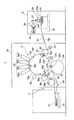
図1に示すように、搬送装置としてのデジタル印刷装置1は、供給部としての給紙装置2、処理部としてのデジタル印刷ユニット3及び排出部としての排紙装置4を備える。
<Configuration of digital printing device>
As shown in FIG. 1, a digital printing apparatus 1 as a transport apparatus includes a paper feeding device 2 as a supply unit, a digital printing unit 3 as a processing unit, and a paper discharge device 4 as a discharge unit.

給紙装置2には、複数のシートS1が積載された積載台21および、その積載台21の最上段のシートS1をフィーダボードFBへ搬送するサッカー装置23が設けられている。サッカー装置23は、第1吸23aおよび第2吸23bを備え、第1吸23aおよび第2吸23bが連続供給バルブ26および間欠供給バルブ27を介して負圧源25と接続されている。   The paper feeding device 2 is provided with a stacking table 21 on which a plurality of sheets S1 are stacked, and a soccer device 23 that conveys the uppermost sheet S1 of the stacking table 21 to the feeder board FB. The soccer device 23 includes a first suction 23 a and a second suction 23 b, and the first suction 23 a and the second suction 23 b are connected to the negative pressure source 25 through a continuous supply valve 26 and an intermittent supply valve 27.

連続供給バルブ26および間欠供給バルブ27は、共に第1吸23aおよび第2吸23bの負圧源25からの吸引を断接するものであるが、後述するように吸引を断接するタイミングがそれぞれ異なっている。   The continuous supply valve 26 and the intermittent supply valve 27 both connect and disconnect the suction from the negative pressure source 25 of the first suction 23a and the second suction 23b, but the timings for connecting and disconnecting the suction are different as will be described later. Yes.

フィーダボードFBのシート搬送方向先端側には、デジタル印刷ユニット3のフレーム3aに揺動自在に支持され、シートS1の一方の端部である先端(くわえ側端部)をくわえて保持する図示しないくわえ爪装置を備えたスイング装置31fが配設されている。スイング装置31fには給紙側渡し胴32が対向して配置され、その給紙側渡し胴32がフレーム3aに回転自在に支持されている。   On the front end side in the sheet conveying direction of the feeder board FB, it is supported by the frame 3a of the digital printing unit 3 so as to be swingable, and holds the front end (the end on the holding side) as one end of the sheet S1. A swing device 31f provided with a gripper device is provided. A paper feed side transfer drum 32 is disposed opposite to the swing device 31f, and the paper feed side transfer drum 32 is rotatably supported by the frame 3a.

給紙側渡し胴32には、スイング装置31fのくわえ爪装置により受け渡されるシートS1の先端をくわえた状態で保持するくわえ爪装置32aが設けられている。なおデジタル印刷ユニット3では、スイング装置31fおよび給紙側渡胴32により上流側シート搬送装置を構成している。   The feeding side transfer cylinder 32 is provided with a gripping claw device 32a that holds the leading end of the sheet S1 delivered by the gripping claw device of the swing device 31f. In the digital printing unit 3, the swing device 31f and the sheet feeding side transfer cylinder 32 constitute an upstream sheet conveying device.

給紙側渡し胴32には、スイング装置31fよりもシート搬送方向下流側に胴としての印刷胴33が対接配置され、その印刷胴33がフレーム3aに回転自在に支持されている。印刷胴33は、給紙側渡し胴32のくわえ爪装置32aからシートS1の先端を受け取って保持する印刷胴くわえ爪装置33a、33b、33cと、この印刷胴くわえ爪装置33a、33b、33cに対応して設けられシートS1を支持する支持面33d、33e、33fとを備え、本実施の形態においては、印刷胴くわえ爪装置と支持面との組が3組設けられた3倍胴として構成されており、その直径も給紙側渡し胴32の3倍の直径を有している。ここで、シートS1を保持する印刷胴くわえ爪装置33a、33b、33cは円周方向に互いに120度位相をずらした状態で設けられている。この実施の形態においては、印刷胴くわえ爪装置33a、33b、33cが本発明でいう「第1のくわえ爪装置」に相当する。 A printing cylinder 33 as a cylinder is disposed in contact with the sheet feeding side transfer cylinder 32 on the downstream side in the sheet conveyance direction from the swing device 31f, and the printing cylinder 33 is rotatably supported by the frame 3a. The printing cylinder 33 includes a printing cylinder holding claw device 33a, 33b, 33c that receives and holds the leading end of the sheet S1 from the holding claw device 32a of the paper feeding side transfer cylinder 32, and the printing cylinder holding claw device 33a, 33b, 33c. Correspondingly provided support surfaces 33d, 33e, 33f for supporting the sheet S1, and in the present embodiment, a triple cylinder is provided in which three sets of the printing cylinder holding nail device and the support surface are provided. The diameter of the paper feeding side transfer cylinder 32 is three times as large. Here, the printing cylinder holding claw devices 33a, 33b, and 33c that hold the sheet S1 are provided in a state where the phases are shifted by 120 degrees in the circumferential direction. In this embodiment, the printing cylinder gripper devices 33a, 33b and 33c correspond to the “first gripper device” in the present invention.

印刷胴33の支持面33d、33e、33fには複数の吸引用孔33h(図3)が各支持面33d、33e、33fの周面全体に形成されており、その複数の吸引用孔33hが負圧源と接続されている。また印刷胴33には、給紙側渡し胴32との対接部分よりもシート搬送方向下流側であり、その対接部分の近傍位置に表面がゴムで構成されたシートローラ51が対向して配置され、そのシートローラ51がフレーム3aに回転自在に支持されている。シートローラ51は、シートS1を印刷胴33の支持面33d、33e、33fに押し付け当該シートS1の皺を伸ばすものである。   A plurality of suction holes 33h (FIG. 3) are formed on the entire peripheral surfaces of the support surfaces 33d, 33e, and 33f on the support surfaces 33d, 33e, and 33f of the printing cylinder 33, and the plurality of suction holes 33h are formed. Connected to negative pressure source. Further, a sheet roller 51 having a surface made of rubber is opposed to the printing cylinder 33 on the downstream side in the sheet conveying direction with respect to the contact portion with the feeding-side transfer cylinder 32 and in the vicinity of the contact portion. The sheet roller 51 is rotatably supported by the frame 3a. The sheet roller 51 presses the sheet S1 against the support surfaces 33d, 33e, and 33f of the printing cylinder 33 and extends the ridges of the sheet S1.

この印刷胴33の給紙側渡し胴32との対接部分よりもシート搬送方向下流側には、当該印刷胴33の周面に対向してインクジェットノズル部34が配置されている。   An ink jet nozzle portion 34 is disposed on the downstream side of the printing cylinder 33 with respect to the sheet feeding side transfer cylinder 32 in the sheet conveying direction so as to face the peripheral surface of the printing cylinder 33.

インクジェットノズル部34には、互いに異なる色のインキがセットされた複数のインクジェットノズルヘッド34a〜34dが印刷胴33の周面に沿ってシート搬送方向に並設され、それぞれが印刷胴33の周面を指向している。インクジェットノズルヘッド34a〜34dは、印刷胴33の支持面33d、33e、33fに複数の吸引用孔33h(図3)を介して全面吸着されたシートS1との隙間が僅かな間隔となるよう印刷胴33に近接して配設されている。なお、印刷胴33、インクジェットノズル部34によりシート印刷装置を構成している。   A plurality of inkjet nozzle heads 34 a to 34 d in which inks of different colors are set are arranged in the inkjet nozzle portion 34 side by side along the circumferential surface of the printing cylinder 33, and each of them is a circumferential surface of the printing cylinder 33. Is oriented. The ink jet nozzle heads 34a to 34d are printed so that the gap between the print surface 33 and the sheet S1 adsorbed on the entire surface through a plurality of suction holes 33h (FIG. 3) is slightly spaced. It is disposed close to the body 33. The printing cylinder 33 and the inkjet nozzle unit 34 constitute a sheet printing apparatus.

印刷胴33のインクジェットノズル部34よりもシート搬送方向下流側には、印刷胴33に対接配置され、シートS1に赤外線や紫外線などの光を照射して当該シートS1上に印刷されたインキを乾燥させる乾燥装置としてのインキ乾燥ランプ35が設けられている。ここで、乾燥とは熱エネルギーを与えてインキの水分を蒸発させることやインキを硬化させることを含むものであり、固化と言い換えることができる。   An ink printed on the sheet S1 by irradiating the sheet S1 with light such as infrared rays or ultraviolet rays is disposed on the downstream side of the printing cylinder 33 in the sheet conveyance direction with respect to the inkjet nozzle portion 34, and is irradiated with light such as infrared rays or ultraviolet rays. An ink drying lamp 35 is provided as a drying device for drying. Here, the term “drying” includes evaporation of moisture of the ink by applying thermal energy and curing of the ink, which can be called solidification.

印刷胴33には、インクジェットノズル部34よりもシート搬送方向下流側に、第1の排紙側渡し胴36が対接配置され、その第1の排紙側渡し胴36がフレーム3aに回転自在に支持されている。第1の排紙側渡し胴36には、印刷胴33により搬送されるシートS1の先端を印刷胴くわえ爪装置33a、33b、33cから受け取って保持するくわえ爪装置36aが設けられている。この実施の形態においては、この第1の排紙側渡し胴36のくわえ爪装置36aが本発明でいう「第2のくわえ爪装置」に相当する。 A first paper discharge side transfer cylinder 36 is disposed in contact with the printing cylinder 33 on the downstream side in the sheet conveying direction from the ink jet nozzle portion 34, and the first paper discharge side transfer cylinder 36 is rotatable to the frame 3a. It is supported by. The first paper discharge side transfer cylinder 36 is provided with a gripping claw device 36a that receives and holds the leading end of the sheet S1 conveyed by the printing cylinder 33 from the printing cylinder gripping claw devices 33a, 33b, and 33c. In this embodiment, the holding claw device 36a of the first discharge side transfer drum 36 corresponds to the “second holding claw device” in the present invention.

第1の排紙側渡し胴36の印刷胴33との対接部分よりもシート搬送方向下流側には、第2の排紙側渡し胴37が第1の排紙側渡し胴36と対接配置され、その第2の排紙側渡し胴37がフレーム3aに回転自在に支持されている。第2の排紙側渡し胴37には、第1の排紙側渡し胴36により搬送されるシートS1の先端を受け取って保持するくわえ爪装置37aが設けられている。   A second paper discharge side transfer cylinder 37 is in contact with the first paper discharge side transfer cylinder 36 on the downstream side of the first paper discharge side transfer cylinder 36 in contact with the printing cylinder 33 in the sheet conveying direction. The second paper discharge side transfer cylinder 37 is rotatably supported by the frame 3a. The second paper discharge side transfer drum 37 is provided with a gripping claw device 37a for receiving and holding the leading edge of the sheet S1 conveyed by the first paper discharge side transfer drum 36.

第2の排紙側渡し胴37の第1の排紙側渡し胴36との対接部分よりもシート搬送方向下流側には紙取胴38が対接配置され、その紙取胴38がフレーム3aに回転自在に支持されている。紙取胴38には、第2の排紙側渡し胴37により搬送されるシートS1の先端を受け取って保持するくわえ爪装置38aが設けられている。   A paper take-up cylinder 38 is disposed in contact with the first paper discharge-side transfer cylinder 37 on the downstream side of the second paper discharge-side transfer cylinder 37 with respect to the first paper discharge-side transfer cylinder 36. 3a is rotatably supported. The paper take-up cylinder 38 is provided with a gripping claw device 38a that receives and holds the leading end of the sheet S1 conveyed by the second paper discharge side transfer cylinder 37.

紙取胴38の下方には、シートS1を搬送するベルトコンベア状のデリバリーベルト40が配設されている。デリバリーベルト40のシート搬送方向先端側には、デジタル印刷ユニット3によりデジタル印刷処理の施されたシートS1を積載する積載台41が設けられている。なお、紙取胴38、デリバリーベルト40、積載台41により排紙装置4を構成し、紙取胴38およびデリバリーベルト40により搬送されるシートS1の経路がシート排出経路を構成する。   Below the paper drum 38, a belt-conveyor-like delivery belt 40 that conveys the sheet S1 is disposed. On the leading end side of the delivery belt 40 in the sheet conveyance direction, a stacking base 41 on which the sheet S1 subjected to digital printing processing by the digital printing unit 3 is stacked is provided. The paper take-up cylinder 38, the delivery belt 40, and the stacking base 41 constitute the paper discharge device 4, and the path of the sheet S1 conveyed by the paper take-up cylinder 38 and the delivery belt 40 constitutes the sheet discharge path.

第2の排紙側渡し胴37の紙取胴38との対接部分よりもシート搬送方向下流側には、反転前倍胴39が対接配置され、その反転前倍胴39がフレーム3aに回転自在に支持されている。反転前倍胴39は、第2の排紙側渡し胴37の2倍の直径を有する2倍胴であり、第2の排紙側渡し胴37により搬送されるシートS1の先端を受け取って保持する単一のくわえ爪装置39aが設けられている。ここで、反転前倍胴39は、両面印刷モードが選択されてシートS1が間欠給紙される場合に用いられるものであるため、くわえ爪装置39aが少なくとも1つ単独で備えられていれば十分であり、それにより構成が簡素化されている。   A pre-reverse double cylinder 39 is disposed in contact with the paper discharge cylinder 38 on the downstream side of the second paper discharge side transfer cylinder 37 and the paper take-up cylinder 38. The pre-reverse double cylinder 39 is disposed on the frame 3a. It is supported rotatably. The pre-inversion double cylinder 39 is a double cylinder having a diameter twice that of the second paper discharge side transfer cylinder 37, and receives and holds the leading end of the sheet S1 conveyed by the second paper discharge side transfer cylinder 37. A single gripper device 39a is provided. Here, since the double cylinder 39 before reversal is used when the duplex printing mode is selected and the sheet S1 is intermittently fed, it is sufficient that at least one gripper device 39a is provided. This simplifies the configuration.

反転前倍胴39の第2の排紙側渡し胴37との対接部分よりもシート搬送方向下流側には、図2に示されるように、シートS1の他方の端部としての後端(尻側端部)を受け取って保持するくわえ爪装置31btを備えた反転スイング装置31bが対向して配置されている。なお、反転スイング装置31bはシートS1の表裏を反転させる反転部を構成する。   As shown in FIG. 2, as shown in FIG. 2, the rear end (the other end portion of the sheet S <b> 1) is located downstream of the contact portion of the pre-reverse double cylinder 39 with the second discharge-side transfer cylinder 37. A reversing swing device 31b provided with a gripper device 31bt for receiving and holding the (butt side end) is disposed oppositely. The reversing swing device 31b constitutes a reversing unit that reverses the front and back of the sheet S1.

反転スイング装置31bは、印刷胴33の第1の排紙側渡し胴36との対接部分よりも印刷胴33の回転方向下流側かつ給紙側渡し胴32との対接部分よりも印刷胴33の回転方向上流側において印刷胴33に対向して配置されている。そして、この反転スイング装置31bは、反転前倍胴39により搬送されるシートS1の後端を受け取る破線で示された受取位置(図1)と、印刷胴33の印刷胴くわえ爪装置33a、33b、33cにシートS1の後端を受け渡す実線で示された受渡位置(図1)との間で揺動自在にフレーム3aに支持されている。なお、第1の排紙側渡し胴36、第2の排紙側渡し胴37、反転前倍胴39、反転スイング装置31bにより反転機構を構成し、第1の排紙側渡し胴36、第2の排紙側渡し胴37、反転前倍胴39、反転スイング装置31bにより搬送されるシートS1の経路がシート反転経路を構成する。   The reversing swing device 31b is located downstream of the printing cylinder 33 in the rotational direction of the printing cylinder 33 with respect to the first discharge-side transfer cylinder 36 and more than the printing cylinder with respect to the feeding cylinder 32. It is disposed opposite to the printing cylinder 33 on the upstream side in the rotational direction of 33. The reversing swing device 31b includes a receiving position (FIG. 1) indicated by a broken line that receives the rear end of the sheet S1 conveyed by the pre-reversing double cylinder 39, and printing cylinder holding claw devices 33a and 33b of the printing cylinder 33. , 33c is supported by the frame 3a so as to be swingable between a delivery position (FIG. 1) indicated by a solid line that delivers the rear end of the sheet S1. The first paper discharge side transfer drum 36, the second paper discharge side transfer drum 37, the pre-reverse double drum 39, and the reverse swing device 31b constitute a reversing mechanism, and the first paper discharge side transfer drum 36, The path of the sheet S1 conveyed by the sheet discharge side transfer cylinder 37, the pre-reverse double cylinder 39, and the reverse swing device 31b constitutes a sheet reverse path.

第2の排紙側渡し胴37のくわえ爪装置37aは、紙取胴38のくわえ爪装置38aと反転前倍胴39のくわえ爪装置39aとに選択的にシートS1を受け渡すことが可能に駆動される。また、紙取胴38のくわえ爪装置38aは、第2の排紙側渡し胴37により搬送されるシートS1の先端を選択的に受け取ることが可能に駆動され、これらくわえ爪装置37a、38aはシートS1の搬送先を排紙装置4または反転スイング装置31bに切替える、すなわち、シートS1の搬送経路をシート排出経路またはシート反転経路に切替える搬送経路切替手段82(図6)を構成する。   The gripping claw device 37a of the second paper discharge side transfer drum 37 can selectively deliver the sheet S1 to the gripping claw device 38a of the paper take-up drum 38 and the gripping claw device 39a of the pre-reverse double cylinder 39. Driven. Further, the gripping claw device 38a of the paper take-up cylinder 38 is driven so as to be able to selectively receive the leading end of the sheet S1 conveyed by the second paper discharge side transfer cylinder 37. The gripping claw devices 37a, 38a A conveyance path switching unit 82 (FIG. 6) is configured to switch the conveyance destination of the sheet S1 to the paper discharge device 4 or the reverse swing device 31b, that is, to switch the conveyance path of the sheet S1 to the sheet discharge route or the sheet reverse route.

<印刷胴の構成>
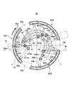
図3乃至図5に示すように印刷胴33の支持面33d、33e、33fには、その周面の矢印で示されるシート搬送方向に所定間隔ごとに複数の吸引孔33hが形成されるとともに、図示しないが、周面のシート幅方向(軸方向)に対しても所定間隔ごとに複数の吸引孔33hが形成されており、かくして多数の吸引孔33hは周面全体にマトリクス状に配置されている。
<Configuration of printing cylinder>
As shown in FIGS. 3 to 5, the support surfaces 33d, 33e, and 33f of the printing cylinder 33 are formed with a plurality of suction holes 33h at predetermined intervals in the sheet conveyance direction indicated by arrows on the peripheral surface. Although not shown, a plurality of suction holes 33h are formed at predetermined intervals also in the sheet width direction (axial direction) of the peripheral surface, and thus a large number of suction holes 33h are arranged in a matrix on the entire peripheral surface. Yes.

印刷胴33は、その周面における印刷胴くわえ爪装置33aと印刷胴くわえ爪装置33bとの間の吸引エリアVA1が、シートS1の先端側を吸引する最下流側の吸引部としてのくわえ側吸引部VA1k、シートS1の中間部分を吸引する中間吸引部VA1m、シートS1の後端側を吸引する紙尻側吸引部VA1hによって円周方向に複数に分割されている。なお、くわえ側吸引部VA1kの円周長は最小シートS1の搬送方向長さに設定されており、したがって、最小シートS1は全面がくわえ側吸引部VA1kに吸引されることになる。   In the printing cylinder 33, the suction side VA1 between the printing cylinder holding claw device 33a and the printing cylinder holding claw device 33b on the peripheral surface thereof is a holding side suction as a most downstream side suction portion that sucks the leading end side of the sheet S1. The sheet is divided into a plurality of parts in the circumferential direction by a part VA1k, an intermediate suction part VA1m that sucks an intermediate part of the sheet S1, and a paper bottom side suction part VA1h that sucks the rear end side of the sheet S1. Note that the circumferential length of the holding side suction portion VA1k is set to the length in the conveyance direction of the minimum sheet S1, and therefore the entire surface of the minimum sheet S1 is sucked by the holding side suction portion VA1k.

くわえ側吸引部VA1kにおける複数の吸引孔33hの下方には吸引室65kが設けられ、中間吸引部VA1mにおける複数の吸引孔33hの下方には吸引室65mが設けられるとともに、紙尻側吸引部VA1hにおける複数の吸引孔33hの下方には吸引室65hが設けられている。ここで吸引室65kはあたかも3つ存在するようにみえるが、空間的に繋がった1つの吸引空間である。   A suction chamber 65k is provided below the plurality of suction holes 33h in the holding side suction part VA1k, a suction chamber 65m is provided below the plurality of suction holes 33h in the intermediate suction part VA1m, and a paper bottom side suction part VA1h. A suction chamber 65h is provided below the plurality of suction holes 33h. Here, although there seem to be three suction chambers 65k, they are one suction space connected spatially.

くわえ側吸引部VA1kの吸引室65kには吸引孔61ksが設けられ、当該吸引孔61ksは印刷胴33の側面に設けられた開口61keと吸引管61kにより接続されている。   A suction hole 61ks is provided in the suction chamber 65k of the holding side suction part VA1k, and the suction hole 61ks is connected to an opening 61ke provided on the side surface of the printing cylinder 33 by a suction pipe 61k.

中間吸引部VA1mの吸引室65mには吸引孔61msが設けられ、吸引孔61msは印刷胴33の側面に設けられた開口61meと吸引管61mにより接続されている。   The suction chamber 65m of the intermediate suction part VA1m is provided with a suction hole 61ms, and the suction hole 61ms is connected to an opening 61me provided on the side surface of the printing cylinder 33 by a suction pipe 61m.

紙尻側吸引部VA1hの吸引室65hには吸引孔61hsが設けられ、吸引孔61hsは印刷胴33の側面に設けられた開口61heと吸引管61hにより接続されている。   A suction hole 61hs is provided in the suction chamber 65h of the paper bottom side suction part VA1h, and the suction hole 61hs is connected to an opening 61he provided on the side surface of the printing cylinder 33 by a suction pipe 61h.

なお図4に示すように印刷胴33は、印刷胴くわえ爪装置33bと印刷胴くわえ爪装置33cとの間の吸引エリアVA2、および印刷胴くわえ爪装置33cと印刷胴くわえ爪装置33aとの間の吸引エリアVA3についても、シート搬送方向に向かってくわえ側吸引部VA2k、VA3k、中間吸引部VA2m、VA3m、および紙尻側吸引部VA2h、VA3hのように分割されている。吸引エリアVA2、VA3については、吸引管62k、63k、吸引管62m、63m及び吸引管62h、63hが設けられているため、吸引エリアVA1と同様の機能を果たすように構成されている。   As shown in FIG. 4, the printing cylinder 33 has a suction area VA2 between the printing cylinder holding nail device 33b and the printing cylinder holding nail device 33c, and between the printing cylinder holding nail device 33c and the printing cylinder holding nail device 33a. The suction area VA3 is also divided into gripping side suction parts VA2k and VA3k, intermediate suction parts VA2m and VA3m, and paper bottom side suction parts VA2h and VA3h in the sheet conveying direction. The suction areas VA2 and VA3 are configured to perform the same function as the suction area VA1 because the suction tubes 62k and 63k, the suction tubes 62m and 63m, and the suction tubes 62h and 63h are provided.

因みに印刷胴33(図3)は、当該印刷胴33(図1)の反対側から見た状態が示されており、吸引エリアVA1乃至VA3等の位置関係が全て逆向きとなっている。フレーム3aには、略C字状でなる吸引切換部としての切換プレート71(図4)が、当該切換プレート71の表面(接触面)が印刷胴33の側面に面接触した状態で取り付けられる。   Incidentally, the printing cylinder 33 (FIG. 3) shows a state viewed from the opposite side of the printing cylinder 33 (FIG. 1), and the positional relationships of the suction areas VA1 to VA3 and the like are all reversed. A switching plate 71 (FIG. 4) serving as a substantially C-shaped suction switching unit is attached to the frame 3 a in a state where the surface (contact surface) of the switching plate 71 is in surface contact with the side surface of the printing cylinder 33.

図5に示すように切換プレート71は、その裏面にスプリング装着穴75a及び75b、76a及び76b、77a及び77b、78a及び78b、79a及び79b、80a及び80bが所定間隔ごとに設けられており、これらのスプリング装着穴にはスプリング(図示せず)が装着され、当該スプリングにより切換プレート71の表面が印刷胴33の側面に押し付けられる。   As shown in FIG. 5, the switching plate 71 is provided with spring mounting holes 75a and 75b, 76a and 76b, 77a and 77b, 78a and 78b, 79a and 79b, 80a and 80b at predetermined intervals on the back surface thereof. A spring (not shown) is mounted in these spring mounting holes, and the surface of the switching plate 71 is pressed against the side surface of the printing cylinder 33 by the spring.

切換プレート71の表面には、くわえ側吸引部VA1k、VA2k、VA3kの開口61ke、62ke、63keが印刷胴33の回転に伴う移動軌跡に沿う円弧状の溝でなる負圧吸引流路72l及び72rが形成されている。但し、負圧吸引流路72l及び72rは別々に形成されるのではなく、負圧吸引流路72lと負圧吸引流路72rとが繋がって一つの負圧吸引流路として形成されても良い。   On the surface of the switching plate 71, negative pressure suction flow paths 72l and 72r each having openings 61ke, 62ke, 63ke of the gripper side suction portions VA1k, VA2k, VA3k are formed as arcuate grooves along the movement trajectory accompanying the rotation of the printing cylinder 33. Is formed. However, the negative pressure suction channels 72l and 72r are not formed separately, but the negative pressure suction channel 72l and the negative pressure suction channel 72r may be connected to form a single negative pressure suction channel. .

また、切換プレート71の表面には、くわえ側吸引部VA1m、VA2m、VA3mの開口61me、62me、63meが印刷胴33の回転に伴う移動軌跡に沿う円弧状の溝でなる負圧吸引流路73l及び73rが形成されている。但し、負圧吸引流路73l及び73rは別々に形成されるのではなく、負圧吸引流路73lと負圧吸引流路73rとが繋がってひとつの負圧吸引流路として形成されても良い。   Further, on the surface of the switching plate 71, the negative pressure suction passage 73l in which the openings 61me, 62me, and 63me of the gripper side suction portions VA1m, VA2m, and VA3m are arc-shaped grooves along the movement trajectory accompanying the rotation of the printing cylinder 33 are provided. And 73r are formed. However, the negative pressure suction channels 73l and 73r are not formed separately, but the negative pressure suction channel 73l and the negative pressure suction channel 73r may be connected to form one negative pressure suction channel. .

さらに、切換プレート71の表面には、くわえ側吸引部VA1h、VA2h、VA3hの開口61he、62he、63heが印刷胴33の回転に伴う移動軌跡に沿う円弧状の溝でなる負圧吸引流路74l及び74rが形成されている。但し、負圧吸引流路74l及び74rは別々に形成されるのではなく、負圧吸引流路74lと負圧吸引流路74rと繋がってひとつの負圧吸引流路として形成されても良い。   Further, on the surface of the switching plate 71, negative pressure suction flow paths 74l in which openings 61he, 62he, 63he of the gripper side suction portions VA1h, VA2h, VA3h are formed as arcuate grooves along the movement trajectory accompanying the rotation of the printing cylinder 33. And 74r are formed. However, the negative pressure suction channels 74l and 74r are not formed separately, but may be formed as one negative pressure suction channel by connecting the negative pressure suction channel 74l and the negative pressure suction channel 74r.

負圧吸引流路72l及び72r、負圧吸引流路73l及び73r、負圧吸引流路74l及び74rには、それぞれ流路口72lx及び72rx、流路口73lx及び73rx、流路口74lx及び74rxが設けられ、これら流路口72lx、72rx、73lx、73rx、74lx、74rxは負圧源(図示せず)と接続されている。従って、これら切換プレート71の流路口72lx及び72rx、流路口73lx及び73rx、流路口74lx及び74rxは、印刷胴33の回転中に、開口61ke〜61he、開口62ke〜62he、開口63ke〜63heと負圧吸引流路72l及び72r、負圧吸引流路73l及び73r、負圧吸引流路74l及び74rを介して連通するように構成されている。   The negative pressure suction channels 72l and 72r, the negative pressure suction channels 73l and 73r, and the negative pressure suction channels 74l and 74r are provided with channel ports 72lx and 72rx, channel ports 73lx and 73rx, and channel ports 74lx and 74rx, respectively. These flow path ports 72lx, 72rx, 73lx, 73rx, 74lx, 74rx are connected to a negative pressure source (not shown). Accordingly, the flow path openings 72lx and 72rx, the flow path openings 73lx and 73rx, and the flow path openings 74lx and 74rx of the switching plate 71 are negatively compared with the openings 61ke to 61he, the openings 62ke to 62he, and the openings 63ke to 63he during the rotation of the printing cylinder 33. The pressure suction flow paths 72l and 72r, the negative pressure suction flow paths 73l and 73r, and the negative pressure suction flow paths 74l and 74r are configured to communicate with each other.

ここで、シートローラ51は、最下流側の吸引部であるくわえ側吸引部VA1kの後端部(くわえ側吸引部VA1kにおける印刷胴33の回転方向の上流側端部)が通過するタイミングで当該くわえ側吸引部VA1kの開口61keが負圧吸引流路72lと対向する位置に設けられている。   Here, the sheet roller 51 is at the timing when the rear end portion of the gripping side suction portion VA1k which is the most downstream suction portion (the upstream end portion in the rotation direction of the printing cylinder 33 in the gripping side suction portion VA1k) passes. The opening 61ke of the holding side suction part VA1k is provided at a position facing the negative pressure suction flow path 72l.

<デジタル印刷装置の制御系の構成>
図6に示すように、デジタル印刷装置1は、全体を統括制御するためのCPU(Central processing Unit)構成でなる制御部としての制御装置81を備えている。制御装置81には、シートS1の片面だけにデジタル印刷処理を施す片面印刷モード、シートS1の表面および裏面の両面にデジタル印刷処理を施す両面印刷モードの何れかを作業者に選択させる印刷モード選択スイッチ80、給紙装置2の連続供給バルブ26および間欠供給バルブ27、インクジェットノズル部34の各インクジェットノズルヘッド34a〜34d、搬送経路切替手段82、シートS1のシート長を入力するシート長入力部85、および、印刷胴33の吸引エリアVA1、VA2、VA3の吸引管61k〜63k、吸引管61m〜63m、吸引管61h〜63hの切替バルブ90が接続されている。
<Configuration of control system of digital printing device>
As illustrated in FIG. 6, the digital printing apparatus 1 includes a control device 81 as a control unit having a CPU (Central processing Unit) configuration for overall control. The control device 81 allows the operator to select either a single-sided printing mode in which digital printing processing is performed on only one side of the sheet S1, or a double-sided printing mode in which digital printing processing is performed on both the front and back surfaces of the sheet S1. The switch 80, the continuous supply valve 26 and the intermittent supply valve 27 of the sheet feeding device 2, the inkjet nozzle heads 34a to 34d of the inkjet nozzle section 34, the conveyance path switching means 82, and the sheet length input section 85 for inputting the sheet length of the sheet S1. The suction pipes 61k to 63k, suction pipes 61m to 63m, and suction pipes 61h to 63h in the suction areas VA1, VA2, and VA3 of the printing cylinder 33 are connected.

<デジタル印刷装置の印刷動作>
このように構成されたデジタル印刷装置1の印刷動作について、片面印刷モードが選択
された場合と、両面印刷モードが選択された場合とに分けて説明する。但し、ここでは、シートS1のシート長は印刷胴33の吸引エリアVA1、VA2およびVA3に相当する最大長さであり、デフォルトとして吸引管61k〜63k、吸引管61m〜63m、吸引管61h〜63hの切替バルブ90が全て「開」となっている場合について説明する。
<Printing operation of digital printing device>
The printing operation of the digital printing apparatus 1 configured as described above will be described separately when the single-sided printing mode is selected and when the double-sided printing mode is selected. However, here, the sheet length of the sheet S1 is the maximum length corresponding to the suction areas VA1, VA2, and VA3 of the printing cylinder 33. By default, the suction tubes 61k to 63k, the suction tubes 61m to 63m, and the suction tubes 61h to 63h A case where all the switching valves 90 are “open” will be described.

図1に示されるように、作業者の印刷モード選択スイッチ80の操作により片面印刷モードが選択されると、制御装置81は連続供給バルブ26を作動させ、これにより第1吸23aおよび第2吸23bが積載台21のシートS1を吸着しフィーダボードFBへ搬送する。   As shown in FIG. 1, when the single-sided printing mode is selected by the operator's operation of the printing mode selection switch 80, the control device 81 activates the continuous supply valve 26, whereby the first suction 23a and the second suction are performed. 23b adsorbs the sheet S1 on the loading table 21 and conveys it to the feeder board FB.

連続供給バルブ26は、印刷胴33の1回転中に当該印刷胴33に設けられた印刷胴くわえ爪装置33a、33b、33cの数と同じ枚数のシートS1を供給するタイミング、換言すると、印刷胴33における印刷胴くわえ爪装置33a乃至33cと、給紙側渡し胴32のくわえ爪装置32aとが対向するタイミング(第1の周期)ごとにバルブが「開」して第1吸23aおよび第2吸23bの負圧源25からの吸引が行なわれるように制御装置81によって制御される。このように、印刷胴33の全ての印刷胴くわえ爪装置33a、33b、33cがシートS1をくわえるように当該シートS1を供給することを連続給紙と呼び、連続給紙における連続供給バルブ26の開閉周期を第1の周期と呼ぶ。連続供給バルブ26の作動により、サッカー装置23はシートS1を第1の周期でフィーダボードFBへ供給する。   The continuous supply valve 26 feeds the same number of sheets S1 as the number of the printing cylinder holding nail devices 33a, 33b, 33c provided in the printing cylinder 33 during one rotation of the printing cylinder 33, in other words, the printing cylinder. The valve is "opened" at each timing (first period) at which the printing cylinder gripping device 33a to 33c in 33 and the gripping device 32a of the paper feeding side transfer cylinder 32 face each other. The controller 81 controls the suction 23b to be sucked from the negative pressure source 25. In this way, supplying the sheet S1 so that all the printing cylinder holding claw devices 33a, 33b, and 33c of the printing cylinder 33 hold the sheet S1 is called continuous feeding, and the continuous supply valve 26 in continuous feeding is used. The opening / closing cycle is referred to as a first cycle. With the operation of the continuous supply valve 26, the soccer device 23 supplies the sheet S1 to the feeder board FB in the first cycle.

フィーダボードFBにより搬送されるシートS1はその先端がスイング装置31fのくわえ爪装置によって保持された後に給紙側渡し胴32へ向かって揺動して搬送され、その給紙側渡し胴32のくわえ爪装置32aに当該シートS1の先端がくわえ替えされる。   The sheet S1 conveyed by the feeder board FB is held by the gripping claw device of the swing device 31f and then oscillated toward the sheet feeding side transfer cylinder 32. The sheet S1 is held by the sheet feeding side transfer cylinder 32. The leading end of the sheet S1 is replaced by the nail device 32a.

給紙側渡し胴32の回転に伴って搬送されるシートS1は、印刷胴33との対接部分において給紙側渡し胴32のくわえ爪装置32aから印刷胴33の印刷胴くわえ爪装置33a〜33cの何れかにその先端がくわえ替えされた後、印刷胴33の回転とともに搬送される。ここで、切換プレート71の表面は印刷胴33の側面に押し付けられているため、印刷胴33は当該切換プレート71の表面と摺接しながら回転する。   The sheet S1 conveyed along with the rotation of the sheet feeding side transfer cylinder 32 is transferred from the gripping claw device 32a of the sheet feeding side transfer cylinder 32 to the printing cylinder holding claw device 33a to 33a of the printing cylinder 33 at the contact portion with the printing cylinder 33. After the tip is replaced by any of 33c, it is conveyed along with the rotation of the printing cylinder 33. Here, since the surface of the switching plate 71 is pressed against the side surface of the printing cylinder 33, the printing cylinder 33 rotates while being in sliding contact with the surface of the switching plate 71.

給紙側渡し胴32のくわえ爪装置32aから印刷胴33の印刷胴くわえ爪装置33bにくわえ替えされたシートS1は、シートローラ51により支持面33dに押し付けられ、印刷胴33の円周方向および/または軸方向に広げられる。これによりシートS1は皺が伸ばされて印刷胴33の支持面33dに密着する。   The sheet S1 that has been replaced by the gripper claw device 33b of the printing cylinder 33 from the gripper claw device 32a of the feeding side transfer cylinder 32 is pressed against the support surface 33d by the sheet roller 51, and the circumferential direction of the printing cylinder 33 and And / or expanded in the axial direction. As a result, the sheet S <b> 1 is stretched and closely contacts the support surface 33 d of the printing cylinder 33.

図7に示すように、くわえ側吸引部VA1kの後端部がシートローラ51を通過するタイミングでは、印刷胴33の回転に伴い、吸引エリアVA1におけるくわえ側吸引部VA1kの開口61keの開口と切換プレート71の負圧吸引流路72lの一方の端部としての開始端とが対向状態になり、吸引室65kと負圧源(図示せず)とが連通状態となるので、くわえ側吸引部VA1kの吸引室65kと連通した複数の吸引孔33hからの吸引が開始される。   As shown in FIG. 7, at the timing when the rear end portion of the gripping side suction portion VA1k passes the sheet roller 51, the opening 61ke of the gripping side suction portion VA1k in the suction area VA1 is switched with the rotation of the printing cylinder 33. Since the starting end as one end of the negative pressure suction flow path 72l of the plate 71 is in an opposing state and the suction chamber 65k and a negative pressure source (not shown) are in communication with each other, the holding side suction portion VA1k Suction from the plurality of suction holes 33h communicating with the suction chamber 65k is started.

吸引管61kの吸引開始タイミングは、印刷胴33の吸引室65kがシートローラ51を通過した直後である。これにより、シートS1はくわえ側吸引部VA1kの範囲でシートローラ51により皺が伸ばされて密着した後に吸着されるため、皺がない状態で支持面33dに密着される。   The suction start timing of the suction pipe 61k is immediately after the suction chamber 65k of the printing cylinder 33 passes the sheet roller 51. As a result, the sheet S1 is attracted by the sheet roller 51 in the range of the gripping side suction portion VA1k and then adsorbed thereto, so that the sheet S1 is in close contact with the support surface 33d without wrinkles.

但し、この時点では、吸引エリアVA1における中間吸引部VA1mの開口61me及び紙尻側吸引部VA1hの開口61heと、切換プレート71の負圧吸引流路73l及び負圧吸引流路74lとが対向状態になっていないため、中間吸引部VA1m及び紙尻側吸引部VA1hにおける吸引は開始されていない。   However, at this time, the opening 61me of the intermediate suction part VA1m and the opening 61he of the paper bottom side suction part VA1h in the suction area VA1 are opposed to the negative pressure suction flow path 73l and the negative pressure suction flow path 74l of the switching plate 71. Therefore, the suction in the intermediate suction part VA1m and the paper bottom side suction part VA1h has not been started.

続いて図8に示すように、くわえ側吸引部VA1kの範囲が吸引され密着したシートS1は、印刷胴33の回転に伴い、その中間部がシートローラ51と対向することにより支持面33dに押し付けられ、印刷胴33の円周方向および/または軸方向に広げられる。これによりシートS1の中間部は皺が伸ばされて印刷胴33の支持面33dに密着される。   Subsequently, as shown in FIG. 8, the sheet S <b> 1 in which the range of the gripping side suction portion VA <b> 1 k is sucked and adhered is pressed against the support surface 33 d by the intermediate portion thereof facing the sheet roller 51 as the printing cylinder 33 rotates. And is expanded in the circumferential direction and / or the axial direction of the printing cylinder 33. As a result, the intermediate portion of the sheet S <b> 1 is stretched and closely attached to the support surface 33 d of the printing cylinder 33.

このとき、吸引エリアVA1における中間吸引部VA1mの開口61meと切換プレート71の負圧吸引流路73lの一方の端部としての開始端とが対向状態になり、吸引室65mと負圧源(図示せず)とが連通状態となるので、中間吸引部VA1mの吸引室65mと連通した複数の吸引孔33hからの吸引が開始される。   At this time, the opening 61me of the intermediate suction portion VA1m in the suction area VA1 and the start end as one end of the negative pressure suction flow path 73l of the switching plate 71 are opposed to each other, and the suction chamber 65m and the negative pressure source (FIG. (Not shown) is in a communication state, and suction from a plurality of suction holes 33h communicating with the suction chamber 65m of the intermediate suction portion VA1m is started.

吸引管61mの吸引開始タイミングは、印刷胴33の吸引室65mとシートローラ51とが対向しているときである。これにより、シートS1は中間吸引部VA1mの範囲でシートローラ51により皺伸ばしされると同時に吸引され、皺がない状態で支持面33dに密着される。   The suction start timing of the suction pipe 61m is when the suction chamber 65m of the printing cylinder 33 and the sheet roller 51 face each other. As a result, the sheet S1 is sucked and simultaneously sucked by the sheet roller 51 in the range of the intermediate suction portion VA1m, and is in close contact with the support surface 33d without any wrinkles.

この時点では、くわえ側吸引部VA1kの開口61keと切換プレート71の負圧吸引流路72lとの対向状態が継続しているため、くわえ側吸引部VA1kの吸引室65kに対する吸引については継続されているが、紙尻側吸引部VA1hの開口61heと、切換プレート71の負圧吸引流路74lの一方の端部としての開始端とは未だ対向状態になっていないため、紙尻側吸引部VA1hにおける吸引は開始されていない。   At this time, since the opening 61ke of the gripper side suction part VA1k and the negative pressure suction flow path 72l of the switching plate 71 continue, the suction of the gripper side suction part VA1k to the suction chamber 65k is continued. However, since the opening 61he of the paper bottom side suction part VA1h and the start end as one end of the negative pressure suction flow path 74l of the switching plate 71 are not yet opposed to each other, the paper bottom side suction part VA1h Aspiration at has not started.

続いて図9に示すように、くわえ側吸引部VA1kおよび中間吸引部VA1mの範囲が吸引され密着したシートS1は、印刷胴33の回転に伴い、その後端部がシートローラ51と対向することにより支持面33dに押し付けられ、印刷胴33の円周方向および/または軸方向に広げられる。これによりシートS1は皺が伸ばされて印刷胴33の支持面33dに密着される。   Subsequently, as shown in FIG. 9, the sheet S <b> 1 in which the range of the gripping side suction part VA <b> 1 k and the intermediate suction part VA <b> 1 m is sucked and closely adhered is caused by the rear end thereof facing the sheet roller 51 as the printing cylinder 33 rotates. It is pressed against the support surface 33d and spreads in the circumferential direction and / or the axial direction of the printing cylinder 33. As a result, the sheet S <b> 1 is stretched and brought into close contact with the support surface 33 d of the printing cylinder 33.

このとき、吸引エリアVA1における紙尻側吸引部VA1hの開口61heの開口と切換プレート71の負圧吸引流路74lの一方の端部としての開始端とが対向状態になり、吸引室65hと負圧源(図示せず)とが連通状態となるので、紙尻側吸引部VA1hの吸引室65hと連通した複数の吸引孔33hからの吸引が開始される。   At this time, the opening 61he of the paper bottom side suction part VA1h in the suction area VA1 and the start end as one end of the negative pressure suction flow path 74l of the switching plate 71 are opposed to each other, and the suction chamber 65h is negative. Since the pressure source (not shown) is in communication, suction from a plurality of suction holes 33h communicating with the suction chamber 65h of the paper bottom side suction part VA1h is started.

吸引管61hの吸引開始タイミングは、印刷胴33の吸引室65hとシートローラ51とが対向しているときである。これにより、シートS1は紙尻側吸引部VA1hの範囲でシートローラ51により皺伸ばしされると同時に吸引され、皺がない状態で支持面33dに密着される。   The suction start timing of the suction pipe 61h is when the suction chamber 65h of the printing cylinder 33 and the sheet roller 51 face each other. As a result, the sheet S1 is stretched and simultaneously sucked by the sheet roller 51 in the range of the paper bottom side suction portion VA1h, and is in close contact with the support surface 33d without any wrinkles.

このとき、くわえ側吸引部VA1k、中間吸引部VA1m、及び紙尻側吸引部VA1hの全てにおいてシートS1に対する吸引が行なわれることになり、シートローラ51により皺の無い状態にされたシートS1の全面が吸引エリアVA1の全体で吸着される。   At this time, suction to the sheet S1 is performed in all of the gripping side suction part VA1k, the intermediate suction part VA1m, and the paper bottom side suction part VA1h, and the entire surface of the sheet S1 that has been free of wrinkles by the sheet roller 51 Is adsorbed in the entire suction area VA1.

このように印刷胴33の回転に伴って、くわえ側吸引部VA1k、中間吸引部VA1m、および紙尻側吸引部VA1hによるシートS1の吸引を順番に開始するので、シートS1を先端から後端へ向かって印刷胴33の周面に次第に吸着させながらインクジェットノズル部34へ搬送することができる。すなわち、シートS1がシートローラ51を通過するくわえ側吸引部VA1k、中間吸引部VA1mおよび紙尻側吸引部VA1hの順番で吸引されるので、シートローラ51を通過する前の無駄な空吸いを防止し、効率的にシートS1を吸引しながらインクジェットノズル部34へ搬送することができる。   As the printing cylinder 33 rotates in this manner, the suction of the sheet S1 by the holding side suction part VA1k, the intermediate suction part VA1m, and the paper bottom side suction part VA1h is started in order, so that the sheet S1 is moved from the leading edge to the trailing edge. The ink can be conveyed to the inkjet nozzle portion 34 while being gradually attracted to the peripheral surface of the printing cylinder 33. That is, since the sheet S1 is sucked in the order of the holding side suction portion VA1k, the intermediate suction portion VA1m, and the paper bottom side suction portion VA1h that pass through the sheet roller 51, unnecessary idle suction before passing through the sheet roller 51 is prevented. In addition, the sheet S1 can be efficiently conveyed to the inkjet nozzle unit 34 while being sucked.

印刷胴33により搬送されるシートS1の表面には、インクジェットノズル部34のインクジェットノズルヘッド34a〜34dから微滴化されたインクが吹き付けられることによりデジタル印刷処理が施される。このときシートS1の全面は、印刷胴33における複数の吸引用孔33hを介して当該印刷胴33の周面に吸着され、インクジェットノズル部34のインクジェットノズルヘッド34a〜34dと最小の微少間隔を維持した状態で搬送される。この微小間隔が維持されることにより吐出されたインクがシートS1に高精度で着弾することができ、高品質な印刷を行うことができる。そして、印刷胴33とインキ乾燥ランプ35との間を通過する際、当該インキ乾燥ランプ35からの光が照射されることによりシートS1のインキが乾燥され、当該シートS1は第1の排紙側渡し胴36へ搬送される。   On the surface of the sheet S <b> 1 conveyed by the printing cylinder 33, digital printing processing is performed by spraying fine droplets of ink from the inkjet nozzle heads 34 a to 34 d of the inkjet nozzle portion 34. At this time, the entire surface of the sheet S1 is adsorbed to the peripheral surface of the printing cylinder 33 through the plurality of suction holes 33h in the printing cylinder 33, and maintains a minimum minute distance from the inkjet nozzle heads 34a to 34d of the inkjet nozzle portion 34. It is conveyed in the state. By maintaining this minute interval, the ejected ink can land on the sheet S1 with high accuracy, and high-quality printing can be performed. Then, when passing between the printing cylinder 33 and the ink drying lamp 35, light from the ink drying lamp 35 is irradiated to dry the ink on the sheet S1, and the sheet S1 is on the first paper discharge side. It is conveyed to the transfer cylinder 36.

その後、図10に示すように、印刷胴33の回転に伴い、吸引エリアVA1におけるくわえ側吸引部VA1kの開口61keの開口と切換プレート71の負圧吸引流路72rの他方の端部としての終了端との対向状態が解消されると、吸引管61kと負圧吸引流路72lとの連通状態が断たれ、負圧源(図示せず)によるくわえ側吸引部VA1kの吸引室65kに対する吸引が終了する。   Thereafter, as shown in FIG. 10, with the rotation of the printing cylinder 33, the opening 61ke of the holding side suction portion VA1k in the suction area VA1 and the end of the switching plate 71 as the other end of the negative pressure suction flow path 72r are completed. When the state of being opposed to the end is eliminated, the communication state between the suction pipe 61k and the negative pressure suction flow path 72l is cut off, and suction to the suction chamber 65k of the holding side suction part VA1k by a negative pressure source (not shown) is performed. finish.

吸引管61kの吸引終了タイミングは、印刷胴33のくわえ爪装置33bから第1の排紙側渡胴36のくわえ爪装置36aにシートS1がくわえ替えされた後であり、シートS1のくわえ側吸引部VA1kに支持された部分が第1の排紙側渡胴36の周面に支持された後である。   The suction end timing of the suction pipe 61k is after the sheet S1 is replaced by the gripping claw device 36a of the first discharge side transfer cylinder 36 from the gripping claw device 33b of the printing cylinder 33, and the gripping side suction of the sheet S1 is performed. This is after the portion supported by the portion VA1k is supported by the peripheral surface of the first paper discharge side transfer drum 36.

但し、この場合、吸引エリアVA1における中間吸引部VA1mの開口61me及び紙尻側吸引部VA1hの開口61heと、切換プレート71の負圧吸引流路73R及び負圧吸引流路74Rとの対向状態が継続されているため、中間吸引部VA1m及び紙尻側吸引部VA1hにおけるシートS1の吸引は継続されている。   In this case, however, the opening 61me of the intermediate suction portion VA1m and the opening 61he of the paper bottom side suction portion VA1h in the suction area VA1 are opposed to the negative pressure suction flow path 73R and the negative pressure suction flow path 74R of the switching plate 71. Since it is continued, the suction of the sheet S1 in the intermediate suction part VA1m and the paper bottom side suction part VA1h is continued.

続いて図11に示すように、更なる印刷胴33の回転に伴い、吸引エリアVA1における中間吸引部VA1mの開口61meと切換プレート71の負圧吸引流路73rの他方の端部としての終了端との対向状態が解消されると、吸引管61mと負圧吸引流路73rとの連通状態が断たれ、負圧源(図示せず)による中間吸引部VA1mの吸引室65mに対する吸引が終了する。   Next, as shown in FIG. 11, with the further rotation of the printing cylinder 33, the opening 61me of the intermediate suction portion VA1m in the suction area VA1 and the end end as the other end of the negative pressure suction flow path 73r of the switching plate 71 When the facing state is eliminated, the communication state between the suction pipe 61m and the negative pressure suction flow path 73r is cut off, and the suction to the suction chamber 65m of the intermediate suction part VA1m by the negative pressure source (not shown) is completed. .

吸引管61mの吸引終了タイミングは、シートS1のうち中間吸引部VA1mの吸引室65mによって吸引された部分が印刷胴33から第1の排紙側渡胴36の周面に支持された後である。   The suction end timing of the suction tube 61m is after the portion of the sheet S1 sucked by the suction chamber 65m of the intermediate suction portion VA1m is supported from the printing cylinder 33 to the peripheral surface of the first discharge side transfer cylinder 36. .

最後に図12に示すように、更なる印刷胴33の回転に伴い、吸引エリアVA1における紙尻側吸引部VA1hの開口61heと切換プレート71の負圧吸引流路74rの他方の端部としての終了端との対向状態が解消されると、吸引管61hと負圧吸引流路73rとの連通状態が断たれ、負圧源(図示せず)による紙尻側吸引部VA1hの吸引室65hに対する吸引が終了する。   Finally, as shown in FIG. 12, with further rotation of the printing cylinder 33, the opening 61he of the paper bottom side suction part VA1h in the suction area VA1 and the other end of the negative pressure suction channel 74r of the switching plate 71 are used. When the opposed state to the end end is eliminated, the communication state between the suction pipe 61h and the negative pressure suction flow path 73r is cut off, and the paper bottom side suction part VA1h with respect to the suction chamber 65h by the negative pressure source (not shown). Suction ends.

吸引管61hの吸引終了タイミングは、シートS1のうち紙尻側吸引部VA1hの吸引室65hによって吸引された部分が印刷胴33から第1の排紙側渡胴36の周面に支持された後、すなわちシートS1の全部が印刷胴33から第1の排紙側渡胴36へ受け渡された後である。   The suction end timing of the suction pipe 61h is after the portion of the sheet S1 sucked by the suction chamber 65h of the paper bottom side suction portion VA1h is supported from the printing cylinder 33 to the peripheral surface of the first discharge side transfer cylinder 36. That is, after the entire sheet S1 has been transferred from the printing cylinder 33 to the first discharge side transfer cylinder 36.

次に、シートS1が最小サイズのシートであり、そのシート長が吸引エリアVA1のくわえ側吸引部VA1kだけで吸引される最短長さである場合と、吸引エリアVA1のくわえ側吸引部VA1kおよび中間吸引部VA1mで吸引される中間長さである場合のシート長に応じた吸引動作について説明する。   Next, the sheet S1 is a minimum-sized sheet, and the sheet length is the shortest length that is sucked only by the holding side suction portion VA1k of the suction area VA1, and the holding side suction portion VA1k and the middle of the suction area VA1. A suction operation according to the sheet length in the case of the intermediate length sucked by the suction portion VA1m will be described.

シートS1のシート長がシート長入力部80を介してユーザにより予め入力されると、その入力結果に基づいて制御装置81がシートS1のシート長を認識する。制御装置81は、例えばシートS1がくわえ側吸引部VA1kにのみ相当する最短長さであることを認識すると、中間吸引部VA1mおよび紙尻側吸引部VA1hにそれぞれ対応した吸引管61mおよび吸引管61hの切替バルブ90を閉め(オフ)、中間吸引部VA1mおよび紙尻側吸引部VA1hの吸引を停止する。   When the sheet length of the sheet S1 is input in advance by the user via the sheet length input unit 80, the control device 81 recognizes the sheet length of the sheet S1 based on the input result. For example, when the control device 81 recognizes that the sheet S1 has the shortest length corresponding only to the holding side suction portion VA1k, the suction tube 61m and the suction tube 61h respectively corresponding to the intermediate suction portion VA1m and the paper bottom side suction portion VA1h. The switching valve 90 is closed (off), and the suction of the intermediate suction part VA1m and the paper bottom side suction part VA1h is stopped.

また制御装置81は、シート長入力部80の入力結果に基づいてシートS1がくわえ側吸引部VA1k及び中間吸引部VA1mに相当する中間長さであることを認識すると、紙尻側吸引部VA1hに対応した吸引管61hの切替バルブ90を閉め(オフ)、紙尻側吸引部VA1hの吸引を停止する。   When the control device 81 recognizes that the sheet S1 has an intermediate length corresponding to the holding side suction portion VA1k and the intermediate suction portion VA1m based on the input result of the sheet length input portion 80, the control device 81 causes the paper bottom side suction portion VA1h to The switching valve 90 of the corresponding suction pipe 61h is closed (off), and the suction of the paper bottom side suction part VA1h is stopped.

これにより、シートS1のシート長がくわえ側吸引部VA1kにのみ相当する最短長さである場合、くわえ側吸引部VA1kだけでシートS1の全面を吸引し、予め中間吸引部VA1mおよび紙尻側吸引部VA1hによる無駄な吸引を行わなせずに済ませることができる。   Thereby, when the sheet length of the sheet S1 is the shortest length corresponding only to the holding side suction portion VA1k, the entire surface of the sheet S1 is sucked only by the holding side suction portion VA1k, and the intermediate suction portion VA1m and the paper bottom side suction are previously sucked. It is possible to dispense with unnecessary suction by the part VA1h.

同様に、シートS1のシート長がシート長入力部80を介してユーザにより予め入力され、シート長がくわえ側吸引部VA1k及び中間吸引部VA1mに相当する中間長さであることを制御部81が認識すると、紙尻側吸引部VA1hに対応した吸引管61hの切替バルブ90だけを閉め(オフ)、紙尻側吸引部VA1hの吸引だけを停止する。   Similarly, the control unit 81 determines that the sheet length of the sheet S1 is input in advance by the user via the sheet length input unit 80, and the sheet length is an intermediate length corresponding to the holding side suction unit VA1k and the intermediate suction unit VA1m. When recognized, only the switching valve 90 of the suction pipe 61h corresponding to the paper bottom side suction part VA1h is closed (off), and only the suction of the paper bottom side suction part VA1h is stopped.

これにより、シートS1のシート長がくわえ側吸引部VA1k及び中間吸引部VA1mに相当する中間長さである場合、くわえ側吸引部VA1kと中間吸引部VA1mとによりシートS1を吸引し、予め紙尻側吸引部VA1hによる無駄な吸引を行わなせずに済ませることができる。   Thereby, when the sheet length of the sheet S1 is an intermediate length corresponding to the holding side suction part VA1k and the intermediate suction part VA1m, the sheet S1 is sucked by the holding side suction part VA1k and the intermediate suction part VA1m in advance, This eliminates unnecessary suction by the side suction unit VA1h.

図13に示すように、印刷胴33と第1の排紙側渡し胴36との対接部分において印刷胴33の印刷胴くわえ爪装置33a〜33cから第1の排紙側渡し胴36のくわえ爪装置36aにシートS1の先端がくわえ替えされる。その後、図14に示すように、第1の排紙側渡し胴36のくわえ爪装置36aに保持されたシートS1は、第1の排紙側渡し胴36と第2の排紙側渡し胴37との対接部分において、第1の排紙側渡し胴36のくわえ爪装置36aから第2の排紙側渡し胴37のくわえ爪装置37aにその先端がくわえ替えされる。   As shown in FIG. 13, in the contact portion between the printing cylinder 33 and the first paper discharge side transfer cylinder 36, the print cylinder holding claw devices 33 a to 33 c of the printing cylinder 33 hold the first paper discharge side transfer cylinder 36. The leading end of the sheet S1 is replaced with the nail device 36a. Thereafter, as shown in FIG. 14, the sheet S <b> 1 held by the holding claw device 36 a of the first paper discharge side transfer drum 36 is transferred to the first paper discharge side transfer drum 36 and the second paper discharge side transfer drum 37. At the contact portion, the gripper claw device 36a of the first paper discharge side transfer drum 36 is replaced with the gripper claw device 37a of the second paper discharge side transfer drum 37.

片面印刷モードの場合、第2の排紙側渡し胴37と紙取胴38との対接部分において、第2の排紙側渡し胴37のくわえ爪装置37aがシートS1の先端の保持を解除するとともに、紙取胴38のくわえ爪装置38aがシートS1の先端をくわえて保持し、くわえ替えが行なわれる。これによりシートS1は第2の排紙側渡し胴37から紙取胴38へくわえ替えされて搬送される。   In the single-sided printing mode, the holding claw device 37a of the second discharge side transfer cylinder 37 releases the holding of the leading edge of the sheet S1 at the contact portion between the second discharge side transfer cylinder 37 and the paper take-up cylinder 38. At the same time, the holding claw device 38a of the paper take-up cylinder 38 holds the leading end of the sheet S1, and the holding is changed. As a result, the sheet S1 is transferred from the second delivery side transfer cylinder 37 to the paper take-up cylinder 38 and conveyed.

紙取胴38にくわえ替えされたシートS1は、デリバリーベルト40の上方に紙取胴38のくわえ爪装置38aが位置したタイミングで当該くわえ爪装置38aによる保持が解除され、デリバリーベルト40上に載せられる。   The sheet S1 that has been replaced by the paper take-up cylinder 38 is released from being held by the holding claw device 38a at the timing when the holding claw device 38a of the paper take-up cylinder 38 is positioned above the delivery belt 40 and placed on the delivery belt 40. It is done.

デリバリーベルト40上に載せられたシートS1は当該デリバリーベルト40の走行とともに搬送され、表面にデジタル印刷処理の施されたシートS1が積載台41上に排出される。   The sheet S1 placed on the delivery belt 40 is conveyed along with the travel of the delivery belt 40, and the sheet S1 whose surface is subjected to digital printing processing is discharged onto the stacking table 41.

一方、作業者の印刷モード選択スイッチ80の操作により両面印刷モードが選択された場合、制御装置81は間欠供給バルブ27を作動し、これにより第1吸23aおよび第2吸23bが積載台21のシートS1を吸着しフィーダボードFBへ搬送する。   On the other hand, when the duplex printing mode is selected by the operator's operation of the printing mode selection switch 80, the control device 81 operates the intermittent supply valve 27, whereby the first suction 23 a and the second suction 23 b are moved to the loading table 21. The sheet S1 is sucked and conveyed to the feeder board FB.

間欠供給バルブ27は、連続給紙のタイミングに対して1枚おきのタイミングでシートS1を供給するタイミング、換言すると、印刷胴33における印刷胴くわえ爪装置33a乃至33cと、給紙側渡し胴32のくわえ爪装置32aとが対向するタイミング(第2の周期)で、バルブが「開」、「閉」、「開」、「閉」、…、となるように制御装置81によって制御される。これは、連続供給の周期の2倍の周期である。このように、印刷胴33の印刷胴くわえ爪装置33a、33b、33cが一つおきにシートS1をくわえるように当該シートS1を供給することを間欠給紙と呼び、間欠給紙における間欠供給バルブ27の開閉周期を第2の周期と呼ぶ。間欠供給バルブ27の作動により、サッカー装置23はシートS1を第2の周期で1枚おきに間欠的に吸着しフィーダボードFBへ搬送する。   The intermittent supply valve 27 supplies the sheet S1 at every other sheet timing with respect to the continuous feeding timing, in other words, the printing cylinder holding claw devices 33a to 33c in the printing cylinder 33 and the feeding side transfer cylinder 32. The control device 81 controls the valve to be “open”, “closed”, “open”, “closed”,... This is twice the period of continuous supply. In this way, feeding the sheet S1 so that the printing cylinder holding claw devices 33a, 33b, 33c of the printing cylinder 33 hold the sheet S1 every other time is called intermittent feeding, and the intermittent supply valve in intermittent feeding The open / close cycle of 27 is referred to as a second cycle. By the operation of the intermittent supply valve 27, the soccer device 23 intermittently sucks every other sheet S1 in the second period and conveys it to the feeder board FB.

サッカー装置23によりフィーダボードFBへ送り出されたシートS1は、片面印刷モードの場合と同様にスイング装置31fおよび給紙側渡し胴32を介して印刷胴33に受け渡されるが、シートS1は間欠給紙のタイミングで送り出されているため、印刷胴33の印刷胴くわえ爪装置33a〜33cは一つおきに給紙側渡し胴32から搬送される新規なシートS1を受取る。 The sheet S1 sent to the feeder board FB by the soccer device 23 is delivered to the printing cylinder 33 via the swing device 31f and the sheet feeding side transfer cylinder 32 as in the single-sided printing mode, but the sheet S1 is intermittently fed. Since the paper is fed at the paper timing, the printing cylinder holding claw devices 33a to 33c of the printing cylinder 33 receive every other new sheet S1 conveyed from the sheet feeding side transfer cylinder 32.

その後、シートS1はインクジェットノズル部34に搬送され、その一方の面(表面)に表面用の印刷が施される。ここで、制御装置81は、印刷胴33の印刷胴くわえ爪装置33a〜33cの一つおきに保持された新規なシートS1に対して印刷を施し、シートS1を保持していない印刷胴くわえ爪装置33a〜33cに対応する支持面33d〜33fに対して印刷を行なわないようにインクジェットノズル部34の各インクジェットノズルヘッド34a〜34dを制御する。   Thereafter, the sheet S1 is conveyed to the inkjet nozzle portion 34, and printing for the surface is performed on one surface (front surface) thereof. Here, the control device 81 performs printing on a new sheet S1 held every other one of the printing cylinder holding nail devices 33a to 33c of the printing cylinder 33, and the printing cylinder holding nail that does not hold the sheet S1. The inkjet nozzle heads 34a to 34d of the inkjet nozzle portion 34 are controlled so that printing is not performed on the support surfaces 33d to 33f corresponding to the devices 33a to 33c.

両面印刷モードの場合には、インクジェットノズル部34により表面に印刷が施されたシートS1は、第2の排紙側渡し胴37から紙取胴38へ受け渡されずに、反転前倍胴39に受け渡される。 In the double-sided printing mode, the sheet S1 printed on the surface by the ink jet nozzle unit 34 is not delivered from the second paper discharge side transfer cylinder 37 to the paper take-up cylinder 38, but before-inversion double cylinder 39. Is passed on.

このように両面印刷モードの場合であって、表面に印刷が施されているが他方の面(裏面)には印刷が施されていない場合には、制御装置81により搬送経路切替手段82が制御され、第2の排紙側渡し胴37と紙取胴38との対接部分において第2の排紙側渡し胴37のくわえ爪装置37aの爪は開かずに閉じたままの状態、すなわちシートS1の先端を保持した状態が維持されるとともに、紙取胴38のくわえ爪装置38aの爪は閉じずに開いた状態が維持される。   Thus, in the case of the duplex printing mode, when printing is performed on the front side but printing is not performed on the other side (back side), the transport path switching means 82 is controlled by the control device 81. The nail of the gripping device 37a of the second paper discharge side transfer cylinder 37 remains closed without opening at the contact portion between the second paper discharge side transfer cylinder 37 and the paper take-up cylinder 38, that is, the sheet. The state in which the tip of S1 is held is maintained, and the claw of the gripping claw device 38a of the paper drum 38 is maintained in an open state without closing.

これによりシートS1は第2の排紙側渡し胴37から紙取胴38へくわえ替えされることなく反転前倍胴39へ搬送される。第2の排紙側渡し胴37と反転前倍胴39との対接部分において反転前倍胴39のくわえ爪装置39aの爪を閉じてシートS1の先端を保持させるとともに、第2の排紙側渡し胴37のくわえ爪装置37aの爪を開いてシートS1の先端の保持を解除させ、図15に示すように、第2の排紙側渡し胴37のくわえ爪装置37aから反転前倍胴39のくわえ爪装置39aにシートS1の先端がくわえ替えされる。   As a result, the sheet S1 is conveyed from the second discharge side transfer drum 37 to the paper take-up drum 38 without being replaced by the pre-inversion double drum 39. The claw of the gripping claw device 39a of the pre-reverse double cylinder 39 is closed at the contact portion between the second paper discharge side transfer cylinder 37 and the pre-reverse double cylinder 39 to hold the leading edge of the sheet S1, and the second paper discharge The nail | claw of the holding nail | claw apparatus 37a of the side transfer cylinder 37 is opened, the holding | maintenance of the front-end | tip of sheet | seat S1 is cancelled | released, and as shown in FIG. The leading end of the sheet S1 is replaced by 39 holding claw devices 39a.

図16に示すように、反転前倍胴39の回転とともに搬送されるシートS1は、反転スイング装置31bが実線で示される受渡位置から破線で示される受取位置へ揺動し、シートS1の後端を当該反転スイング装置31bのくわえ爪装置31btにより保持すると同時に、反転前倍胴39のくわえ爪装置39aによるシートS1の先端に対する保持を解除する。   As shown in FIG. 16, the sheet S1 conveyed along with the rotation of the pre-reverse double cylinder 39 swings the reverse swing device 31b from the delivery position indicated by the solid line to the reception position indicated by the broken line, and the rear end of the sheet S1. Is held by the holding claw device 31bt of the reversing swing device 31b, and at the same time, the holding of the double cylinder 39 before reversing to the leading end of the sheet S1 by the holding claw device 39a is released.

図17に示すように、反転スイング装置31bの破線で示す受取位置から実線で示す受渡位置への揺動によりシートS1はその後端を先頭にして印刷胴33に向けて搬送され、反転スイング装置31bのくわえ爪装置31btから印刷胴33の印刷胴くわえ爪装置33a〜33cの何れかに表裏反転状態のシートS1の後端がくわえ替えされる。   As shown in FIG. 17, the sheet S1 is conveyed toward the printing cylinder 33 with the trailing edge at the head by swinging from the receiving position indicated by the broken line to the delivery position indicated by the solid line of the reverse swing device 31b, and the reverse swing device 31b. The rear end of the sheet S1 in the reversed state is switched from the gripper nail device 31bt to any of the print cylinder gripper nail devices 33a to 33c of the printing cylinder 33.

ここで、印刷胴33の印刷胴くわえ爪装置33a〜33cは給紙側渡し胴32から搬送される新規なシートS1を一つおきに保持しているのであるが、反転スイング装置31bは新規なシートS1を保持しない印刷胴くわえ爪装置33a〜33cと対向するタイミングで受渡位置へ位置付けられ、反転スイング装置31bのくわえ爪装置31btからシートS1の後端を印刷胴くわえ爪装置33a〜33cへ受け渡す。これにより、印刷胴33の印刷胴くわえ爪装置33a〜33cには、給紙側渡し胴32から受け渡された新規なシートS1と反転スイング装置31bのくわえ爪装置31btから受け渡された表裏反転状態のシートS1とが交互に保持され、インクジェットノズル部34へ搬送される。
Here, the printing cylinder holding claw devices 33a to 33c of the printing cylinder 33 hold every other new sheet S1 conveyed from the sheet feeding side transfer cylinder 32, but the reverse swing device 31b is a new one. positioned to the transfer position at a timing opposite to the printing cylinder gripper device 33a to 33c have while preserving the sheet S1, the trailing end of the printing cylinder gripper device of the sheet S1 to gripper device 31bt inversion swing device 31b 33a to 33c Hand over to. As a result, the front and back of the new sheet S1 delivered from the paper feeding side transfer cylinder 32 and the front and back reversal device 31bt of the reversing swing device 31b are transferred to the print cylinder holding claw devices 33a to 33c of the printing cylinder 33. The sheet S1 in the state is held alternately and conveyed to the ink jet nozzle unit 34.

このとき反転スイング装置31bのくわえ爪装置31btから受け渡された表裏反転状態のシートS1は、インクジェットノズル部34により既にデジタル印刷処理の施された表面(デジタル印刷処理済みの面)が印刷胴33の支持面33d、33e、33fと対接し、シートS1の裏面(デジタル印刷未処理の面)が露出した状態で、シートS1の後端が印刷胴33の印刷胴くわえ爪装置33a〜33cにより保持された状態のまま搬送される。   At this time, the sheet S1 in the reverse state, which has been transferred from the gripper device 31bt of the reversing swing device 31b, has a surface that has already been subjected to digital printing processing by the inkjet nozzle unit 34 (surface that has been subjected to digital printing processing). In contact with the support surfaces 33d, 33e, and 33f of the sheet S1, and the rear surface of the sheet S1 is exposed (surface not yet processed by digital printing), and the rear end of the sheet S1 is held by the printing cylinder holding nail devices 33a to 33c of the printing cylinder 33. It is transported as it is.

シートS1の後端が保持された状態で印刷胴33とシートローラ51との間を通過する際、当該シートローラ51によって当該シートS1が引き伸ばされ、皺の無い状態のシートS1が印刷胴33の印刷胴くわえ爪装置33a〜33cの何れかによりくわえられ、かつ、片面印刷モードの場合と同様に、当該シートS1の全面が複数の吸引用孔33hにより皺の無い状態で全面吸着されながらインクジェットノズル部34へ向かって搬送される。   When the sheet S1 passes between the printing cylinder 33 and the sheet roller 51 with the trailing end of the sheet S1 held, the sheet S1 is stretched by the sheet roller 51, and the sheet S1 without wrinkles is formed on the printing cylinder 33. As in the case of the single-sided printing mode, the entire surface of the sheet S1 is picked up by the plurality of suction holes 33h while being adsorbed on the entire surface without wrinkles, as in the case of the single-sided printing mode. It is conveyed toward the section 34.

ここで、制御装置81は、反転スイング装置31bのくわえ爪装置31btから受け渡された表裏反転状態のシートS1に対しては裏面用の印刷を施し、印刷胴33のくわえ爪装置33a〜33cのひとつおきに保持された新規なシートS1に対しては表面用の印刷を施すようにインクジェットノズル部34の各インクジェットノズルヘッド34a〜34dを制御する。これにより、インクジェットノズルヘッド34a〜34dは、印刷胴33に交互に保持された新規なシートS1と表裏反転状態のシートS1に対応して表面用の印刷と裏面用の印刷を交互に行うことになる。 Here, the control device 81 performs printing for the back side of the sheet S1 in the front and back inverted state transferred from the gripping claw device 31bt of the reversing swing device 31b, and the gripping claw devices 33a to 33c of the printing cylinder 33. The ink jet nozzle heads 34a to 34d of the ink jet nozzle unit 34 are controlled so as to perform printing for the front surface for every other new sheet S1 held. As a result, the inkjet nozzle heads 34a to 34d alternately perform printing for the front surface and printing for the back surface corresponding to the new sheet S1 held alternately on the printing cylinder 33 and the sheet S1 in the reverse state. Become.

その後、裏面に裏面用の印刷が施されたシートS1は、片面印刷モードの場合と同様に、第1の排出側渡し胴36、第2の排紙側渡し胴37、紙取胴38を順次介してデリバリーベルト40から排紙装置4の積載台41へ排出される。   Thereafter, the sheet S1 printed on the back side is printed on the first discharge side transfer drum 36, the second discharge side transfer drum 37, and the paper drum 38 in the same manner as in the single-sided printing mode. Then, the paper is discharged from the delivery belt 40 to the loading table 41 of the paper discharge device 4.

<他の実施の形態>
なお、上述した実施の形態においては、シートS1のシート長がシート長入力部85を介してユーザにより入力されると、制御装置81がシートS1のシート長さを認識し、吸引エリアVA1におけるくわえ側吸引部VA1k、中間吸引部VA1mおよび紙尻側吸引部VA1hの吸引を切替バルブ90を介して個別に制御するようにした場合について述べた。
<Other embodiments>
In the above-described embodiment, when the sheet length of the sheet S1 is input by the user via the sheet length input unit 85, the control device 81 recognizes the sheet length of the sheet S1 and holds it in the suction area VA1. The case where the suction of the side suction part VA1k, the intermediate suction part VA1m and the paper bottom side suction part VA1h is individually controlled via the switching valve 90 has been described.

本発明はこれに限るものではなく、吸引エリアVA1におけるくわえ側吸引部VA1k、中間吸引部VA1mおよび紙尻側吸引部VA1hの吸引を個別に制御することにくわえて、更に、シートS1のシート幅(印刷胴33の軸方向の長さ)に対応させて吸引を制御するようにしても良い。すなわち、吸引部をシート搬送方向長さである円周方向だけでなくシート幅方向にも複数に分割して、シート幅入力部(図示せず)に入力されたシート幅に基づいて、制御装置81がシート幅方向へ分割しておいた複数の吸引部の吸引を個別に制御するようにしても良い。   The present invention is not limited to this. In addition to individually controlling the suction of the holding side suction part VA1k, the intermediate suction part VA1m, and the paper bottom side suction part VA1h in the suction area VA1, the sheet width of the sheet S1 is further increased. The suction may be controlled corresponding to (the length of the printing cylinder 33 in the axial direction). That is, the control unit is configured to divide the suction unit into a plurality of not only in the circumferential direction which is the length in the sheet conveyance direction but also in the sheet width direction, and based on the sheet width input to the sheet width input unit (not shown) The suction of a plurality of suction portions 81 divided in the sheet width direction may be individually controlled.

また、上述した実施の形態においては、シートS1のシート長がシート長入力部85を介してユーザにより入力されると、制御装置81がシート長さを認識し、吸引エリアVA1におけるくわえ側吸引部VA1k、中間吸引部VA1mおよび紙尻側吸引部VA1hの吸引を切替バルブ90を介して個別に制御するようにした場合について述べた。しかしながら、本発明はこれに限らず、図6との対応部分に同一符号を付した図18に示すように、印刷胴33の位相を検出するロータリーエンコーダ87および給紙側渡し胴32の近傍に設けられた光電センサでなるシート有無検知センサ86が制御装置81に接続された構成であれば、ロータリーエンコーダ87により検出された印刷胴33の位相においてシート有無検知センサ86によるシートS1の有無を検知することによりシートS1のシート長を算出し、そのシート長に応じて吸引エリアVA1におけるくわえ側吸引部VA1k、中間吸引部VA1mおよび紙尻側吸引部VA1hの吸引を個別に制御するようにしても良い。   In the above-described embodiment, when the sheet length of the sheet S1 is input by the user via the sheet length input unit 85, the control device 81 recognizes the sheet length, and the holding side suction unit in the suction area VA1. The case where the suction of the VA1k, the intermediate suction part VA1m, and the paper bottom side suction part VA1h is individually controlled via the switching valve 90 has been described. However, the present invention is not limited to this, and as shown in FIG. 18 in which parts corresponding to those in FIG. 6 are assigned the same reference numerals, the rotary encoder 87 for detecting the phase of the printing cylinder 33 and the feeding side transfer cylinder 32 are located in the vicinity. If the sheet presence / absence detection sensor 86, which is a photoelectric sensor provided, is connected to the control device 81, the presence / absence of the sheet S1 is detected by the sheet presence / absence detection sensor 86 in the phase of the printing cylinder 33 detected by the rotary encoder 87. Thus, the sheet length of the sheet S1 is calculated, and the suction of the holding side suction portion VA1k, the intermediate suction portion VA1m, and the paper bottom side suction portion VA1h in the suction area VA1 is individually controlled according to the sheet length. good.

さらに、上述した実施の形態においては、3倍胴でなる印刷胴33を用いるようにした場合について述べたが、本発明はこれに限らず、2倍胴、4倍胴、6倍胴等でなる印刷胴を用いるようにしてもよい。   Further, in the above-described embodiment, the case where the printing cylinder 33 having a triple cylinder is used has been described. However, the present invention is not limited to this, and the double cylinder, the quadruple cylinder, the six cylinder, etc. A printing cylinder may be used.

さらに、上述した実施の形態においては、本発明の搬送装置をデジタル印刷装置1に適用するようにした場合について述べたが、本発明はこれに限らず、シートS1を皺の無い状態で搬送することの必要なオフセット印刷装置、検査装置等に適用するようにしてもよい。   Furthermore, in the above-described embodiment, the case where the conveyance device of the present invention is applied to the digital printing device 1 has been described. However, the present invention is not limited to this, and the sheet S1 is conveyed without wrinkles. The present invention may be applied to an offset printing apparatus, an inspection apparatus, or the like that requires this.

1…デジタル印刷装置(搬送装置)、2…給紙装置、3…デジタル印刷ユニット、4…排紙装置、21…積載板、23…サッカー装置、25…負圧源、26…連続供給バルブ、27…間欠供給バルブ、31b…反転スイング装置、31f…スイング装置、32…給紙側渡し胴、33…印刷胴(胴)、33h…吸引用孔、34…インクジェットノズル部、35…インキ乾燥ランプ、36…第1の排紙側渡し胴、37…第2の排紙側渡し胴、38…紙取胴、39…反転前倍胴、41…デリバリーベルト、FB…フィーダボード、S1…シート、51…シートローラ、61〜63…吸引管、71…切換プレート(吸引切換部)、72〜74…吸引流路、80…印刷モード選択スイッチ、81…制御装置、85…シート長入力部、82…搬送経路切替手段、87…ロータリーエンコーダ、90…吸引管の切替バルブ、VA1〜VA3…吸引エリア。   DESCRIPTION OF SYMBOLS 1 ... Digital printing apparatus (conveyance apparatus), 2 ... Paper feeding apparatus, 3 ... Digital printing unit, 4 ... Paper discharge apparatus, 21 ... Stacking board, 23 ... Soccer device, 25 ... Negative pressure source, 26 ... Continuous supply valve, 27 ... intermittent supply valve, 31b ... reverse swing device, 31f ... swing device, 32 ... paper feed side transfer cylinder, 33 ... printing cylinder (cylinder), 33h ... suction hole, 34 ... inkjet nozzle section, 35 ... ink drying lamp , 36 ... first discharge side transfer cylinder, 37 ... second discharge side transfer cylinder, 38 ... paper cylinder, 39 ... pre-reversal double cylinder, 41 ... delivery belt, FB ... feeder board, S1 ... sheet, DESCRIPTION OF SYMBOLS 51 ... Sheet roller, 61-63 ... Suction tube, 71 ... Switching plate (suction switching part), 72-74 ... Suction flow path, 80 ... Print mode selection switch, 81 ... Control apparatus, 85 ... Sheet length input part, 82 ... Transfer route switching Stage, 87 ... rotary encoder, 90 ... switching valve of the suction pipe, VAl to VA3 ... suction area.

Claims (4)

シートを吸引して搬送する胴を備えた搬送装置において、
前記胴に設けられ、シートを支持する支持面の周面全面に形成された複数の吸引用孔を有し、シートの全面を吸引する吸引エリアと、
前記吸引エリアを円周方向に分割する複数の吸引部と、
前記胴に対向して設けられ、シートと対接して当該シートを伸ばすシートローラと、
負圧源と複数の前記吸引部との間に設けられ、前記負圧源とそれぞれの前記吸引部との接続を断接し、前記胴の回転に伴い複数の前記吸引部を当該胴の回転方向の下流側の吸引部から上流側の吸引部へ順番に前記負圧源と接続させる吸引切換部と
を備え、
複数の前記吸引部は、前記胴の側面に設けられ吸引室と連通する開口を備え、
前記吸引切換部は、フレームに支持され前記胴の前記側面に接触し、当該胴の前記側面との接触面に前記開口の移動軌跡に沿う円弧状に形成され前記負圧源と接続された複数の負圧吸引流路が設けられる切換プレートを備え、
前記吸引切換部は、前記吸引部のうち最下流側の吸引部が前記シートローラを通過するタイミングで前記吸引切換部による最下流側の前記吸引部のシートの吸引が開始する
ことを特徴とする搬送装置。
In a transport device equipped with a drum that sucks and transports a sheet,
A suction area that is provided in the cylinder and has a plurality of suction holes formed on the entire peripheral surface of the support surface that supports the sheet, and sucks the entire surface of the sheet;
A plurality of suction sections that divide the suction area in a circumferential direction;
A sheet roller provided facing the cylinder and extending the sheet in contact with the sheet;
Provided between a negative pressure source and a plurality of the suction portions, the connection between the negative pressure source and each of the suction portions is disconnected, and the plurality of suction portions are rotated in the rotation direction of the barrel along with the rotation of the barrel. A suction switching unit for connecting the negative pressure source in order from the downstream suction unit to the upstream suction unit,
The plurality of suction portions include an opening provided on a side surface of the trunk and communicating with a suction chamber,
The suction switching unit is supported by a frame, contacts the side surface of the cylinder, and is formed in an arc shape along the movement trajectory of the opening on the contact surface with the side surface of the cylinder, and is connected to the negative pressure source. A switching plate provided with a negative pressure suction flow path of
The suction switching unit is configured to start suction of a sheet of the suction unit on the most downstream side by the suction switching unit at a timing when the suction unit on the most downstream side of the suction unit passes the sheet roller. Conveying device.
前記負圧吸引流路は前記胴の径方向に複数設けられていることを特徴とする請求項1に記載の搬送装置。The conveying apparatus according to claim 1, wherein a plurality of the negative pressure suction flow paths are provided in a radial direction of the body. 前記最下流側の吸引部の円周方向長さが、最小サイズのシートの搬送方向長さと等しい ことを特徴とする請求項1に記載の搬送装置。   The conveyance device according to claim 1, wherein a circumferential direction length of the most downstream suction unit is equal to a conveyance direction length of a minimum size sheet. 前記胴に設けられ、シートの先端を保持する第1のくわえ爪装置と、A first nail device provided on the cylinder and holding a leading edge of the sheet;
前記胴のシート搬送方向下流側に設けられた排紙側渡し胴と、A paper discharge side transfer cylinder provided downstream of the cylinder in the sheet conveying direction;
前記排紙側渡し胴に設けられた第2のくわえ爪装置と、A second gripper device provided on the paper discharge side transfer cylinder;
を備え、With
前記吸引切換部は、前記第1のくわえ爪装置から前記第2のくわえ爪装置にシートがくわえ替えされた後吸引を終了することを特徴とする請求項1に記載の搬送装置。2. The transport device according to claim 1, wherein the suction switching unit ends the suction after the sheet is replaced by the second gripper device from the first gripper device. 3.
JP2013087129A 2012-04-24 2013-04-18 Transport device Active JP6002622B2 (en)

Priority Applications (1)

Application Number Priority Date Filing Date Title
JP2013087129A JP6002622B2 (en) 2012-04-24 2013-04-18 Transport device

Applications Claiming Priority (3)

Application Number Priority Date Filing Date Title
JP2012098710 2012-04-24
JP2013087129A JP6002622B2 (en) 2012-04-24 2013-04-18 Transport device

Publications (3)

Publication Number Publication Date
JP2013241272A JP2013241272A (en) 2013-12-05
JP2013241272A5 JP2013241272A5 (en) 2015-07-30
JP6002622B2 true JP6002622B2 (en) 2016-10-05

Family

ID=49842591

Family Applications (1)

Application Number Title Priority Date Filing Date
JP2013087129A Active JP6002622B2 (en) 2012-04-24 2013-04-18 Transport device

Country Status (1)

Country Link
JP (1) JP6002622B2 (en)

Families Citing this family (9)

* Cited by examiner, † Cited by third party
Publication number Priority date Publication date Assignee Title
JP6529347B2 (en) * 2015-06-05 2019-06-12 株式会社小森コーポレーション Printer
JP7069869B2 (en) * 2018-03-13 2022-05-18 株式会社リコー Transport equipment, printing equipment
JP2020019637A (en) 2018-08-01 2020-02-06 株式会社リコー Sheet suction device, sheet transport device, printing device, suction area switching device
JP7419777B2 (en) 2019-12-06 2024-01-23 コニカミノルタ株式会社 Image forming device and cooling method
JP2021116156A (en) 2020-01-27 2021-08-10 株式会社リコー Sheet suction device, sheet transport device, printer and suction region switching device
JP2021120323A (en) 2020-01-31 2021-08-19 株式会社リコー Sheet suction device, sheet transport device, printer, and suction area switch device
JP7443791B2 (en) 2020-01-31 2024-03-06 株式会社リコー Sheet suction device, sheet conveyance device, printing device, suction area switching device
JP7443792B2 (en) 2020-01-31 2024-03-06 株式会社リコー Sheet suction device, sheet conveyance device, printing device, suction area switching device
JP2022081942A (en) 2020-11-20 2022-06-01 株式会社リコー Sheet suction apparatus, sheet conveyance apparatus and printer

Family Cites Families (14)

* Cited by examiner, † Cited by third party
Publication number Priority date Publication date Assignee Title
JPS62199341A (en) * 1986-02-21 1987-09-03 Aisin Warner Ltd Detecting device for pin or rod fracture
JP3297141B2 (en) * 1993-04-23 2002-07-02 大日本印刷株式会社 Windowless and film bonding equipment
JP3401711B2 (en) * 1993-12-22 2003-04-28 パナソニック コミュニケーションズ株式会社 Image recording device
JP3410313B2 (en) * 1997-01-07 2003-05-26 東芝テック株式会社 Medium holding device for inkjet printer
JP3450620B2 (en) * 1997-01-22 2003-09-29 東芝テック株式会社 Inkjet printer
JP3600727B2 (en) * 1997-03-28 2004-12-15 大日本スクリーン製造株式会社 Printing equipment
JP2001022088A (en) * 1999-07-12 2001-01-26 Matsushita Graphic Communication Systems Inc Image recorder
JP2001206585A (en) * 2000-01-24 2001-07-31 Noritsu Koki Co Ltd Suction feed mechanism for paper, suction feed method for paper, and printer device having the same
JP3935797B2 (en) * 2001-07-23 2007-06-27 三菱重工業株式会社 Sheet-fed printing press
JP5299736B2 (en) * 2007-09-04 2013-09-25 Nltテクノロジー株式会社 Film sticking device
JP4478897B2 (en) * 2008-03-05 2010-06-09 富士フイルム株式会社 Medium holding apparatus, image recording apparatus, and image forming apparatus
JP4943366B2 (en) * 2008-03-31 2012-05-30 富士フイルム株式会社 Conveying body and image forming apparatus
JP5350933B2 (en) * 2009-07-31 2013-11-27 富士フイルム株式会社 Medium fixing device and image forming apparatus
JP5422458B2 (en) * 2010-03-25 2014-02-19 富士フイルム株式会社 Medium conveying apparatus, image forming apparatus, and medium conveying method

Also Published As

Publication number Publication date
JP2013241272A (en) 2013-12-05

Similar Documents

Publication Publication Date Title
JP6002622B2 (en) Transport device
JP2013240997A (en) Conveying device
US20160288538A1 (en) Digital printing apparatus
US11220410B2 (en) Sheet suction device, sheet conveying device incorporating the sheet suction device, printer incorporating the sheet conveying device, and suction area switcher
JP6030979B2 (en) Sheet transport device
JP6224919B2 (en) Sheet processing device
JP6584255B2 (en) Sheet feeding device
US8899584B2 (en) Sheet reversing device
JP2014168962A (en) Printing apparatus
JP6178598B2 (en) Printing device
JP2013240989A (en) Liquid transfer device
JP6133108B2 (en) Sheet feeding device
JP2013241277A (en) Sheet conveyance device
JP2013241267A (en) Conveyance device
JP2008213181A (en) Recording medium conveying device and printing machine
JP7443792B2 (en) Sheet suction device, sheet conveyance device, printing device, suction area switching device
JP7443791B2 (en) Sheet suction device, sheet conveyance device, printing device, suction area switching device
US11407604B2 (en) Sheet suction device, sheet conveyor, printer, and suction area switching device
JP2013241276A (en) Sheet digital printer
JP6104690B2 (en) Inverted sheet processing device
JP2024013368A (en) sheet processing equipment
JP2013249205A (en) Printing apparatus
JP6067464B2 (en) Sheet processing device
JP2013241274A (en) Swing device
JP5443313B2 (en) Print sheet transport device

Legal Events

Date Code Title Description
A521 Written amendment

Free format text: JAPANESE INTERMEDIATE CODE: A523

Effective date: 20150612

A621 Written request for application examination

Free format text: JAPANESE INTERMEDIATE CODE: A621

Effective date: 20150612

A977 Report on retrieval

Free format text: JAPANESE INTERMEDIATE CODE: A971007

Effective date: 20160420

A131 Notification of reasons for refusal

Free format text: JAPANESE INTERMEDIATE CODE: A131

Effective date: 20160510

A521 Written amendment

Free format text: JAPANESE INTERMEDIATE CODE: A523

Effective date: 20160705

TRDD Decision of grant or rejection written
A01 Written decision to grant a patent or to grant a registration (utility model)

Free format text: JAPANESE INTERMEDIATE CODE: A01

Effective date: 20160816

A61 First payment of annual fees (during grant procedure)

Free format text: JAPANESE INTERMEDIATE CODE: A61

Effective date: 20160905

R150 Certificate of patent or registration of utility model

Ref document number: 6002622

Country of ref document: JP

Free format text: JAPANESE INTERMEDIATE CODE: R150