JP4692485B2 - Raw material alloy and powder for rare earth magnet and method for producing sintered magnet - Google Patents
Raw material alloy and powder for rare earth magnet and method for producing sintered magnet Download PDFInfo
- Publication number
- JP4692485B2 JP4692485B2 JP2006519516A JP2006519516A JP4692485B2 JP 4692485 B2 JP4692485 B2 JP 4692485B2 JP 2006519516 A JP2006519516 A JP 2006519516A JP 2006519516 A JP2006519516 A JP 2006519516A JP 4692485 B2 JP4692485 B2 JP 4692485B2
- Authority
- JP
- Japan
- Prior art keywords
- alloy
- temperature
- rare earth
- cooling
- manufacturing
- Prior art date
- Legal status (The legal status is an assumption and is not a legal conclusion. Google has not performed a legal analysis and makes no representation as to the accuracy of the status listed.)
- Active
Links
Images


Classifications
-
- B—PERFORMING OPERATIONS; TRANSPORTING
- B22—CASTING; POWDER METALLURGY
- B22F—WORKING METALLIC POWDER; MANUFACTURE OF ARTICLES FROM METALLIC POWDER; MAKING METALLIC POWDER; APPARATUS OR DEVICES SPECIALLY ADAPTED FOR METALLIC POWDER
- B22F9/00—Making metallic powder or suspensions thereof
- B22F9/02—Making metallic powder or suspensions thereof using physical processes
- B22F9/023—Hydrogen absorption
-
- B—PERFORMING OPERATIONS; TRANSPORTING
- B22—CASTING; POWDER METALLURGY
- B22F—WORKING METALLIC POWDER; MANUFACTURE OF ARTICLES FROM METALLIC POWDER; MAKING METALLIC POWDER; APPARATUS OR DEVICES SPECIALLY ADAPTED FOR METALLIC POWDER
- B22F9/00—Making metallic powder or suspensions thereof
- B22F9/002—Making metallic powder or suspensions thereof amorphous or microcrystalline
-
- C—CHEMISTRY; METALLURGY
- C22—METALLURGY; FERROUS OR NON-FERROUS ALLOYS; TREATMENT OF ALLOYS OR NON-FERROUS METALS
- C22C—ALLOYS
- C22C1/00—Making non-ferrous alloys
- C22C1/04—Making non-ferrous alloys by powder metallurgy
- C22C1/0433—Nickel- or cobalt-based alloys
- C22C1/0441—Alloys based on intermetallic compounds of the type rare earth - Co, Ni
-
- C—CHEMISTRY; METALLURGY
- C22—METALLURGY; FERROUS OR NON-FERROUS ALLOYS; TREATMENT OF ALLOYS OR NON-FERROUS METALS
- C22C—ALLOYS
- C22C1/00—Making non-ferrous alloys
- C22C1/04—Making non-ferrous alloys by powder metallurgy
- C22C1/047—Making non-ferrous alloys by powder metallurgy comprising intermetallic compounds
-
- C—CHEMISTRY; METALLURGY
- C22—METALLURGY; FERROUS OR NON-FERROUS ALLOYS; TREATMENT OF ALLOYS OR NON-FERROUS METALS
- C22C—ALLOYS
- C22C33/00—Making ferrous alloys
- C22C33/02—Making ferrous alloys by powder metallurgy
- C22C33/0257—Making ferrous alloys by powder metallurgy characterised by the range of the alloying elements
- C22C33/0278—Making ferrous alloys by powder metallurgy characterised by the range of the alloying elements with at least one alloying element having a minimum content above 5%
-
- C—CHEMISTRY; METALLURGY
- C22—METALLURGY; FERROUS OR NON-FERROUS ALLOYS; TREATMENT OF ALLOYS OR NON-FERROUS METALS
- C22C—ALLOYS
- C22C38/00—Ferrous alloys, e.g. steel alloys
- C22C38/005—Ferrous alloys, e.g. steel alloys containing rare earths, i.e. Sc, Y, Lanthanides
-
- H—ELECTRICITY
- H01—ELECTRIC ELEMENTS
- H01F—MAGNETS; INDUCTANCES; TRANSFORMERS; SELECTION OF MATERIALS FOR THEIR MAGNETIC PROPERTIES
- H01F1/00—Magnets or magnetic bodies characterised by the magnetic materials therefor; Selection of materials for their magnetic properties
- H01F1/01—Magnets or magnetic bodies characterised by the magnetic materials therefor; Selection of materials for their magnetic properties of inorganic materials
- H01F1/03—Magnets or magnetic bodies characterised by the magnetic materials therefor; Selection of materials for their magnetic properties of inorganic materials characterised by their coercivity
- H01F1/032—Magnets or magnetic bodies characterised by the magnetic materials therefor; Selection of materials for their magnetic properties of inorganic materials characterised by their coercivity of hard-magnetic materials
- H01F1/04—Magnets or magnetic bodies characterised by the magnetic materials therefor; Selection of materials for their magnetic properties of inorganic materials characterised by their coercivity of hard-magnetic materials metals or alloys
- H01F1/047—Alloys characterised by their composition
- H01F1/053—Alloys characterised by their composition containing rare earth metals
- H01F1/055—Alloys characterised by their composition containing rare earth metals and magnetic transition metals, e.g. SmCo5
- H01F1/057—Alloys characterised by their composition containing rare earth metals and magnetic transition metals, e.g. SmCo5 and IIIa elements, e.g. Nd2Fe14B
- H01F1/0571—Alloys characterised by their composition containing rare earth metals and magnetic transition metals, e.g. SmCo5 and IIIa elements, e.g. Nd2Fe14B in the form of particles, e.g. rapid quenched powders or ribbon flakes
- H01F1/0575—Alloys characterised by their composition containing rare earth metals and magnetic transition metals, e.g. SmCo5 and IIIa elements, e.g. Nd2Fe14B in the form of particles, e.g. rapid quenched powders or ribbon flakes pressed, sintered or bonded together
- H01F1/0577—Alloys characterised by their composition containing rare earth metals and magnetic transition metals, e.g. SmCo5 and IIIa elements, e.g. Nd2Fe14B in the form of particles, e.g. rapid quenched powders or ribbon flakes pressed, sintered or bonded together sintered
-
- H—ELECTRICITY
- H01—ELECTRIC ELEMENTS
- H01F—MAGNETS; INDUCTANCES; TRANSFORMERS; SELECTION OF MATERIALS FOR THEIR MAGNETIC PROPERTIES
- H01F41/00—Apparatus or processes specially adapted for manufacturing or assembling magnets, inductances or transformers; Apparatus or processes specially adapted for manufacturing materials characterised by their magnetic properties
- H01F41/02—Apparatus or processes specially adapted for manufacturing or assembling magnets, inductances or transformers; Apparatus or processes specially adapted for manufacturing materials characterised by their magnetic properties for manufacturing cores, coils, or magnets
- H01F41/0253—Apparatus or processes specially adapted for manufacturing or assembling magnets, inductances or transformers; Apparatus or processes specially adapted for manufacturing materials characterised by their magnetic properties for manufacturing cores, coils, or magnets for manufacturing permanent magnets
- H01F41/0266—Moulding; Pressing
-
- B—PERFORMING OPERATIONS; TRANSPORTING
- B22—CASTING; POWDER METALLURGY
- B22F—WORKING METALLIC POWDER; MANUFACTURE OF ARTICLES FROM METALLIC POWDER; MAKING METALLIC POWDER; APPARATUS OR DEVICES SPECIALLY ADAPTED FOR METALLIC POWDER
- B22F3/00—Manufacture of workpieces or articles from metallic powder characterised by the manner of compacting or sintering; Apparatus specially adapted therefor ; Presses and furnaces
- B22F3/10—Sintering only
- B22F2003/1032—Sintering only comprising a grain growth inhibitor
-
- B—PERFORMING OPERATIONS; TRANSPORTING
- B22—CASTING; POWDER METALLURGY
- B22F—WORKING METALLIC POWDER; MANUFACTURE OF ARTICLES FROM METALLIC POWDER; MAKING METALLIC POWDER; APPARATUS OR DEVICES SPECIALLY ADAPTED FOR METALLIC POWDER
- B22F2998/00—Supplementary information concerning processes or compositions relating to powder metallurgy
- B22F2998/10—Processes characterised by the sequence of their steps
-
- B—PERFORMING OPERATIONS; TRANSPORTING
- B22—CASTING; POWDER METALLURGY
- B22F—WORKING METALLIC POWDER; MANUFACTURE OF ARTICLES FROM METALLIC POWDER; MAKING METALLIC POWDER; APPARATUS OR DEVICES SPECIALLY ADAPTED FOR METALLIC POWDER
- B22F2999/00—Aspects linked to processes or compositions used in powder metallurgy
-
- C—CHEMISTRY; METALLURGY
- C21—METALLURGY OF IRON
- C21D—MODIFYING THE PHYSICAL STRUCTURE OF FERROUS METALS; GENERAL DEVICES FOR HEAT TREATMENT OF FERROUS OR NON-FERROUS METALS OR ALLOYS; MAKING METAL MALLEABLE, e.g. BY DECARBURISATION OR TEMPERING
- C21D1/00—General methods or devices for heat treatment, e.g. annealing, hardening, quenching or tempering
- C21D1/18—Hardening; Quenching with or without subsequent tempering
- C21D1/19—Hardening; Quenching with or without subsequent tempering by interrupted quenching
-
- H—ELECTRICITY
- H01—ELECTRIC ELEMENTS
- H01F—MAGNETS; INDUCTANCES; TRANSFORMERS; SELECTION OF MATERIALS FOR THEIR MAGNETIC PROPERTIES
- H01F1/00—Magnets or magnetic bodies characterised by the magnetic materials therefor; Selection of materials for their magnetic properties
- H01F1/01—Magnets or magnetic bodies characterised by the magnetic materials therefor; Selection of materials for their magnetic properties of inorganic materials
- H01F1/03—Magnets or magnetic bodies characterised by the magnetic materials therefor; Selection of materials for their magnetic properties of inorganic materials characterised by their coercivity
- H01F1/032—Magnets or magnetic bodies characterised by the magnetic materials therefor; Selection of materials for their magnetic properties of inorganic materials characterised by their coercivity of hard-magnetic materials
- H01F1/04—Magnets or magnetic bodies characterised by the magnetic materials therefor; Selection of materials for their magnetic properties of inorganic materials characterised by their coercivity of hard-magnetic materials metals or alloys
- H01F1/047—Alloys characterised by their composition
- H01F1/053—Alloys characterised by their composition containing rare earth metals
- H01F1/055—Alloys characterised by their composition containing rare earth metals and magnetic transition metals, e.g. SmCo5
- H01F1/058—Alloys characterised by their composition containing rare earth metals and magnetic transition metals, e.g. SmCo5 and IVa elements, e.g. Gd2Fe14C
-
- H—ELECTRICITY
- H01—ELECTRIC ELEMENTS
- H01F—MAGNETS; INDUCTANCES; TRANSFORMERS; SELECTION OF MATERIALS FOR THEIR MAGNETIC PROPERTIES
- H01F1/00—Magnets or magnetic bodies characterised by the magnetic materials therefor; Selection of materials for their magnetic properties
- H01F1/01—Magnets or magnetic bodies characterised by the magnetic materials therefor; Selection of materials for their magnetic properties of inorganic materials
- H01F1/03—Magnets or magnetic bodies characterised by the magnetic materials therefor; Selection of materials for their magnetic properties of inorganic materials characterised by their coercivity
- H01F1/032—Magnets or magnetic bodies characterised by the magnetic materials therefor; Selection of materials for their magnetic properties of inorganic materials characterised by their coercivity of hard-magnetic materials
- H01F1/04—Magnets or magnetic bodies characterised by the magnetic materials therefor; Selection of materials for their magnetic properties of inorganic materials characterised by their coercivity of hard-magnetic materials metals or alloys
- H01F1/047—Alloys characterised by their composition
- H01F1/053—Alloys characterised by their composition containing rare earth metals
- H01F1/055—Alloys characterised by their composition containing rare earth metals and magnetic transition metals, e.g. SmCo5
- H01F1/059—Alloys characterised by their composition containing rare earth metals and magnetic transition metals, e.g. SmCo5 and Va elements, e.g. Sm2Fe17N2
Landscapes
- Chemical & Material Sciences (AREA)
- Engineering & Computer Science (AREA)
- Materials Engineering (AREA)
- Mechanical Engineering (AREA)
- Metallurgy (AREA)
- Organic Chemistry (AREA)
- Power Engineering (AREA)
- Crystallography & Structural Chemistry (AREA)
- Inorganic Chemistry (AREA)
- Manufacturing & Machinery (AREA)
- Hard Magnetic Materials (AREA)
- Manufacture Of Metal Powder And Suspensions Thereof (AREA)
- Powder Metallurgy (AREA)
- Continuous Casting (AREA)
- Manufacturing Cores, Coils, And Magnets (AREA)
Description
本発明は、希土類磁石用原料合金、および、その粉末の製造方法に関し、また、希土類磁石用原料合金粉末を用いて焼結磁石を製造する方法に関している。 The present invention relates to a rare earth magnet raw material alloy and a method for producing the powder, and also relates to a method for producing a sintered magnet using the rare earth magnet raw material alloy powder.
ネオジム・鉄・硼素系磁石は、種々の磁石の中で最も高い磁気エネルギー積を示し、価格も比較的安いため、HDD、MRI、およびモータなどの重要部品として各種電子機器へ積極的に採用されている。 Neodymium / iron / boron magnets have the highest magnetic energy product among various magnets and are relatively inexpensive. Therefore, they are actively used in various electronic devices as important parts such as HDDs, MRIs, and motors. ing.
ネオジム・鉄・硼素系磁石は、Nd2Fe14B型結晶を主相とする磁石であるが、より一般的に「R−T−B系磁石」と称される場合がある。ここで、Rは希土類元素、TはFeを主とするNiやCoで代表される遷移金属元素、Bは硼素である。ただし、Bの一部は、C、N、Al、Si、および/またはPなどの元素によって置換され得るため、本明細書では、B、C、N、Al、Si、およびPからなる群から選択された少なくとも1種の元素を「Q」と表記し、「ネオジム・鉄・硼素系磁石」と称されている希土類磁石を広く「R−T−Q系希土類磁石」と記載する。R−T−Q系希土類磁石では、R2T14Q結晶粒が主相を構成している。A neodymium / iron / boron-based magnet is a magnet having an Nd 2 Fe 14 B-type crystal as a main phase, but may be more generally referred to as an “RTB-based magnet”. Here, R is a rare earth element, T is a transition metal element represented by Ni or Co mainly containing Fe, and B is boron. However, since a part of B can be substituted by an element such as C, N, Al, Si, and / or P, in this specification, from the group consisting of B, C, N, Al, Si, and P The selected at least one element is denoted as “Q”, and rare earth magnets called “neodymium / iron / boron magnets” are broadly referred to as “RTQ rare earth magnets”. In the RTQ-based rare earth magnet, R 2 T 14 Q crystal grains constitute the main phase.
R−T−Q系希土類磁石用原料合金の粉末は、当該原料合金の粗粉砕を行う第1粉砕工程と、原料合金の微粉砕を行う第2粉砕工程とを含む方法によって作製されることが多い。例えば、第1粉砕工程では水素脆化処理によって原料合金を数百μm以下のサイズに粗く粉砕した後、第2粉砕工程では、粗粉砕された原料合金(粗粉砕粉)をジェットミル粉砕装置などによって平均粒径が数μm程度のサイズに細かく粉砕する。 The raw material alloy powder for the RTQ-based rare earth magnet may be produced by a method including a first pulverization step for coarsely pulverizing the raw material alloy and a second pulverization step for finely pulverizing the raw material alloy. Many. For example, in the first pulverization process, the raw material alloy is roughly pulverized to a size of several hundred μm or less by hydrogen embrittlement treatment, and then in the second pulverization process, the coarsely pulverized raw material alloy (coarse pulverized powder) is jet mill pulverizer, etc. To finely pulverize to an average particle size of about several μm.
磁石用原料合金自体の作製方法には大きく分けて2種類ある。第1の方法は、所定組成の合金溶湯を鋳型に入れ、比較的ゆっくりと冷却するインゴット鋳造法である。第2の方法は、所定組成の合金溶湯を単ロール、双ロール、回転ディスク、または回転円筒鋳型等に接触させて急速に冷却し、合金溶湯からインゴット合金よりも薄い凝固合金を作製するストリップキャスト法や遠心鋳造法に代表される急冷法である。 There are roughly two types of methods for producing the magnet raw alloy itself. The first method is an ingot casting method in which a molten alloy having a predetermined composition is placed in a mold and cooled relatively slowly. The second method is a strip casting in which a molten alloy having a predetermined composition is brought into contact with a single roll, a twin roll, a rotating disk, or a rotating cylindrical mold, and rapidly cooled to produce a solidified alloy thinner than the ingot alloy from the molten alloy. This is a rapid cooling method typified by the process and centrifugal casting.
このような急冷法による場合、合金溶湯の冷却速度は、例えば101℃/秒以上104℃/秒以下の範囲にある。そして、急冷法によって作製された急冷合金の厚さは、0.03mm以上10mm以下の範囲にある。合金溶湯は冷却ロールの接触した面(ロール接触面)から凝固し、ロール接触面から厚さ方向に結晶が柱状(針状)に成長してゆく。その結果、上記急冷合金は、短軸方向サイズが3μm以上10μm以下で長軸方向サイズが10μm以上300μm以下のR2T14Q結晶相と、R2T14Q結晶相の粒界に分散して存在するRリッチ相(希土類元素Rの濃度が相対的に高い相)とを含有する微細結晶組織を持つにいたる。Rリッチ相は希土類元素Rの濃度が比較的に高い非磁性相であり、その厚さ(粒界の幅に相当する)は10μm以下である。In the case of such a rapid cooling method, the cooling rate of the molten alloy is, for example, in the range of 10 1 ° C / second to 10 4 ° C / second. And the thickness of the quenching alloy produced by the quenching method exists in the range of 0.03 mm or more and 10 mm or less. The molten alloy solidifies from the contact surface (roll contact surface) of the cooling roll, and crystals grow in a columnar shape (needle shape) in the thickness direction from the roll contact surface. As a result, the quenched alloy is dispersed at the grain boundaries of the R 2 T 14 Q crystal phase having a minor axis size of 3 μm to 10 μm and a major axis size of 10 μm to 300 μm, and the R 2 T 14 Q crystal phase. A fine crystal structure containing an R-rich phase (a phase in which the concentration of the rare earth element R is relatively high). The R-rich phase is a nonmagnetic phase in which the concentration of the rare earth element R is relatively high, and its thickness (corresponding to the width of the grain boundary) is 10 μm or less.
急冷合金は、従来のインゴット鋳造法(鋳型鋳造法)によって作製された合金(インゴット合金)に比較して、相対的に短時間で冷却されているため、組織が微細化され、結晶粒径が小さい。また、結晶粒が微細に分散して粒界の面積が広く、Rリッチ相は粒界内を薄く広がっているため、Rリッチ相の分散性にも優れ、焼結性が向上する。このため、特性の優れたR−T−Q系希土類焼結磁石を製造する場合には、その原料として、急冷合金が使用されるようになってきている。 The quenched alloy is cooled in a relatively short time compared to an alloy (ingot alloy) produced by a conventional ingot casting method (mold casting method), so that the structure is refined and the crystal grain size is reduced. small. Further, since the crystal grains are finely dispersed and the area of the grain boundary is wide and the R-rich phase spreads thinly in the grain boundary, the R-rich phase is excellent in dispersibility and the sinterability is improved. For this reason, when an RTQ-based rare earth sintered magnet having excellent characteristics is manufactured, a quenched alloy has been used as a raw material.
希土類合金(特に急冷合金)に水素ガスをいったん吸蔵させ、いわゆる水素粉砕処理によって粗粉砕を行う場合(本明細書では、このような粉砕方法を「水素脆化処理」と称する)、粒界に位置するRリッチ相が水素と反応し、膨張するため、Rリッチ相の部分(粒界部分)から割れる傾向にある。そのため、希土類合金を水素粉砕することによって得られた粉末の粒子表面にはRリッチ相が現われやすくなる。また、急冷合金の場合は、Rリッチ相が微細化されており、その分散性も高いため、水素粉砕粉の表面にはRリッチ相が特に露出しやすい。 When a rare earth alloy (especially a quenched alloy) is once occluded with hydrogen gas and coarsely pulverized by so-called hydrogen pulverization (in this specification, this pulverization method is referred to as “hydrogen embrittlement”), the grain boundary Since the positioned R-rich phase reacts with hydrogen and expands, it tends to break from the R-rich phase portion (grain boundary portion). Therefore, an R-rich phase tends to appear on the particle surface of the powder obtained by hydrogen pulverizing the rare earth alloy. In the case of a quenched alloy, the R-rich phase is miniaturized and its dispersibility is high, so that the R-rich phase is particularly easily exposed on the surface of the hydrogen pulverized powder.
上記の水素脆化処理による粉砕方法は、例えば米国特許出願09/503,738に開示されている。 The above-mentioned pulverization method by hydrogen embrittlement is disclosed in, for example, US patent application 09 / 503,738.
このようなR−T−Q系希土類磁石の保磁力を高めるため、希土類Rの一部をDy、Tb、および/またはHoで置換する技術が知られている。なお、本明細書では、Dy、Tb、およびHoからなる群から選択された少なくとも1種の元素をRHと表記することする。In order to increase the coercive force of such an RTQ-based rare earth magnet, a technique for replacing a part of the rare earth R with Dy, Tb, and / or Ho is known. In the present specification, at least one element selected from the group consisting of Dy, Tb, and Ho is denoted as RH .
しかしながら、R−T−Q系希土類磁石用原料合金に添加した元素RHは、合金溶湯の急冷後、主相であるR2T14Q相にだけではなく、粒界相にもほぼ一様に存在することになる。このような粒界相に存在する元素RHは、保磁力の向上に寄与しないという問題がある。However, the element RH added to the raw material alloy for the RTQ-based rare earth magnet is substantially uniform not only in the main phase R 2 T 14 Q phase but also in the grain boundary phase after the molten alloy is quenched. Will exist. There is a problem that the element RH present in such a grain boundary phase does not contribute to the improvement of the coercive force.
また、粒界に元素RHが多く存在することにより焼結性が低下するとう問題もある。この問題は、原料合金に占める元素RHの割合が1.5原子%以上の場合に大きくなり、この割合が2.0原子%以上になると顕著なものとなる。There is also a problem that sinterability deteriorates due to the presence of a large amount of element RH at the grain boundary. This problem becomes significant when the ratio of the element RH in the raw material alloy is 1.5 atomic% or more, and becomes prominent when this ratio is 2.0 atomic% or more.
また、凝固合金の粒界相部分は、水素脆化処理および微粉砕工程によって超微粉(粒径:1μm以下)となりやすく、かりに微粉末にならなかったとしても、露出した粉末表面を構成しやすい。超微粉は、酸化や発火の問題を引き起こしやすく、また、焼結にも悪影響を与えるため、粉砕工程中に除去される。粒径1μm以上の粉末粒子の表面に露出している希土類は酸化されやすく、また、元素RHはNdやPrよりも酸化されやすいため、合金の粒界相中に存在した元素RHは、安定な酸化物を形成してしまい、主相の希土類元素Rと置換することなく、粒界相に偏析した状態を維持しやすい。Further, the grain boundary phase portion of the solidified alloy tends to become ultrafine powder (particle diameter: 1 μm or less) by hydrogen embrittlement treatment and fine pulverization process, and even if it does not become fine powder, it tends to constitute the exposed powder surface . Ultrafine powder is easily removed during the pulverization process because it tends to cause oxidation and ignition problems and also has an adverse effect on sintering. Rare earth is easily oxidized exposed on the surface of the particle size 1μm or more powder particles, also, since the element R H is easily oxidized than Nd and Pr, the element R H that was present in the grain boundary phase of the alloy, A stable oxide is formed, and it is easy to maintain the state segregated in the grain boundary phase without replacing the rare earth element R of the main phase.
以上のことから、急冷合金中の元素RHのうち、その粒界相に存在する部分は保磁力向上のために有効利用されないという問題がある。元素RHは、希少な元素であり、価格も高いため、資源の有効利用や製造コストの低下という観点から、上述のような無駄を排除することが強く求められている。From the above, there is a problem that the portion present in the grain boundary phase of the element RH in the quenched alloy is not effectively used for improving the coercive force. Since the element RH is a rare element and has a high price, it is strongly required to eliminate the above-mentioned waste from the viewpoint of effective use of resources and reduction in manufacturing cost.
このような問題を解決するため、特許文献1は、ストリップキャスト法で作製した急冷凝固合金に対して、400〜800℃の温度範囲で5分〜12時間保持する熱処理工程を施すことにより、粒界に存在する重希土類を主相に濃縮することを開示している。 In order to solve such a problem,
なお、このようにDyを主相に濃縮することを目的とはしていないが、急冷合金の組織を調整する目的で、合金溶湯の急冷プロセスを制御することが特許文献2や特許文献3に開示されている。 Although not intended to concentrate Dy in the main phase in this way,
特許文献2は、急冷合金の組織を微細化するため、合金溶湯を急冷する過程を一次冷却と二次冷却の2つの段階に区分し、各段階における冷却速度を特定範囲に制御することを開示している。
特許文献3は、冷却ロールによって合金溶湯を急冷することによって薄帯状の急冷凝固合金を作製した直後に、その急冷凝固合金を収容容器内に収め、急冷凝固合金の温度を制御することを開示している。特許文献3の開示する方法では、急冷途中において合金温度が900℃から600℃に低下するときの平均冷却速度を10〜300℃/分に制御することにより、Rリッチ相の分布を調節している。
しかし、上記の従来技術には、以下に説明する問題がある。 However, the above prior art has the following problems.
特許文献1の方法では、急冷合金を一旦元素の拡散が生じない温度(例えば室温)まで冷却した後に、急冷装置とは別の炉で急冷合金を加熱することにより、前述した400〜800℃の熱処理行っている。このように急冷工程が完了した後に熱処理を行なうには、熱処理温度まで急冷合金を加熱するプロセスが必要になり、製造作業が煩雑となるだけでなく、結晶粒が粗大化して保磁力が低下するという不都合がある。 In the method of
特許文献2や特許文献3に開示されている方法では、急冷合金の組織を微細化したり、Rリッチ相を分散化することは達成できても、Dyなどの特定希土類元素を粒界から主相に拡散させることはできない。 In the methods disclosed in
本発明はかかる諸点に鑑みてなされたものであり、その主な目的は、製造工程を煩雑化することなく、Dy、Tb、およびHoを主相に濃縮して保磁力を効果的に向上させることのできるR−Fe−Q系希土類磁石の製造方法を提供することにある。 The present invention has been made in view of the above points, and its main purpose is to effectively improve the coercive force by concentrating Dy, Tb, and Ho into the main phase without complicating the production process. Another object of the present invention is to provide a method for producing an R—Fe—Q rare earth magnet that can be used.
本発明によるR−T−Q系希土類磁石用原料合金の製造方法は、R−T−Q系希土類合金(Rは希土類元素、Tは遷移金属元素、QはB、C、N、Al、Si、およびPからなる群から選択された少なくとも1種の元素)であって、希土類元素Rとして、Nd、Pr、Y、La、Ce、Pr、Sm、Eu、Gd、Er、Tm、Yb、およびLuからなる群から選択された少なくとも1種の元素RLと、Dy、Tb、およびHoからなる群から選択された少なくとも1種の元素RHとを含有する合金の溶湯を用意する工程と、前記合金の溶湯を700℃以上1000℃以下の温度まで急冷することによって凝固合金を形成する第1冷却工程と、前記凝固合金を、700℃以上900℃以下の温度範囲に含まれる温度で15秒以上600秒以下のあいだ保持する温度保持工程と、前記凝固合金を400℃以下の温度まで冷却する第2冷却工程とを包含する。The manufacturing method of the RTQ-based rare earth magnet alloy according to the present invention includes the RTQ-based rare earth alloy (R is a rare earth element, T is a transition metal element, Q is B, C, N, Al, Si And at least one element selected from the group consisting of P and N, and the rare earth element R includes Nd, Pr, Y, La, Ce, Pr, Sm, Eu, Gd, Er, Tm, Yb, and Providing a molten metal of an alloy containing at least one element RL selected from the group consisting of Lu and at least one element RH selected from the group consisting of Dy, Tb, and Ho; A first cooling step in which a molten alloy is rapidly cooled to a temperature of 700 ° C. or higher and 1000 ° C. or lower to form a solidified alloy; and the solidified alloy is heated at a temperature included in a temperature range of 700 ° C. or higher and 900 ° C. or lower for 15 seconds. 600 seconds or less It includes a temperature holding step of holding between, and a second cooling step of cooling the solidified alloy to a temperature of 400 ° C. or less.
好ましい実施形態において、前記温度保持工程は、前記凝固合金の温度を前記温度範囲に含まれる前記温度に保持する際、前記凝固合金の温度を10℃/分以下の冷却速度で低下させる工程および/または前記凝固合金の温度を1℃/分以下の昇温速度で上昇させる工程を含む。 In a preferred embodiment, the temperature holding step includes a step of reducing the temperature of the solidified alloy at a cooling rate of 10 ° C./min or less when the temperature of the solidified alloy is held at the temperature included in the temperature range. Or the process of raising the temperature of the said solidified alloy with the temperature increase rate of 1 degrees C / min or less is included.
好ましい実施形態において、前記第1冷却工程は、前記合金の溶湯の温度を102℃/秒以上104℃/秒以下の冷却速度で低下させる工程を含む。In a preferred embodiment, the first cooling step includes a step of reducing the temperature of the molten metal of the alloy at a cooling rate of 10 2 ° C / second or more and 10 4 ° C / second or less.
好ましい実施形態において、前記第2冷却工程は、前記凝固合金の温度を10℃/秒以上の冷却速度で低下させる工程を含む。 In a preferred embodiment, the second cooling step includes a step of reducing the temperature of the solidified alloy at a cooling rate of 10 ° C./second or more.
好ましい実施形態において、前記元素RHは、含有希土類元素全体の5原子%以上を占める。In a preferred embodiment, the element RH occupies 5 atomic% or more of the entire contained rare earth element.
好ましい実施形態において、前記第2冷却工程直後における前記凝固合金中のR2T14Q相に含まれる元素RHの原子数比率が希土類元素全体に占める元素RHの原子数比率よりも大きい。In a preferred embodiment, the atomic ratio of the element RH contained in the R 2 T 14 Q phase in the solidified alloy immediately after the second cooling step is larger than the atomic ratio of the element RH in the entire rare earth element.
好ましい実施形態において、前記第2冷却工程直後における前記凝固合金中のR2T14Q相に含まれる元素RHの原子数比率は、含有希土類元素全体に占める元素RHの原子数比率の1.1倍よりも大きい。In a preferred embodiment, the atomic ratio of the element RH contained in the R 2 T 14 Q phase in the solidified alloy immediately after the second cooling step is 1 of the atomic ratio of the element RH in the entire contained rare earth element. Greater than 1 time.
好ましい実施形態において、希土類元素Rは全体の11原子%以上17原子%以下、遷移金属元素Tは全体の75原子%以上84原子%以下、元素Qは全体の5原子%以上8原子%以下である。 In a preferred embodiment, the rare earth element R is 11 atomic% to 17 atomic% in total, the transition metal element T is 75 atomic% to 84 atomic% in total, and the element Q is 5 atomic% to 8 atomic% in total. is there.
好ましい実施形態において、前記合金は、Ti、V、Cr、Mn、Ni、Cu、Zn、Ga、Zr、Nb、Mo、In、Sn、Hf、Ta、W、およびPbからなる群から選択された少なくとも1種の添加元素Mを含有する。 In a preferred embodiment, the alloy is selected from the group consisting of Ti, V, Cr, Mn, Ni, Cu, Zn, Ga, Zr, Nb, Mo, In, Sn, Hf, Ta, W, and Pb. At least one additive element M is contained.
好ましい実施形態において、前記第1冷却工程は、回転する冷却ロールによって前記合金の溶湯を冷却する工程を含む。 In a preferred embodiment, the first cooling step includes a step of cooling the molten alloy using a rotating cooling roll.
好ましい実施形態において、前記温度保持工程は、700℃以上900℃以下の温度に加熱された部材で前記急冷凝固合金に熱を供給する工程を含む。 In a preferred embodiment, the temperature holding step includes a step of supplying heat to the rapidly solidified alloy with a member heated to a temperature of 700 ° C. or higher and 900 ° C. or lower.
本発明によるR−T−Q系希土類磁石用原料合金粉末の製造方法は、上記いずれかの製造方法によって製造されたR−T−Q系希土類磁石用原料合金を水素脆化法によって脆化させる工程と、前記脆化されたR−T−Q系希土類磁石用原料合金を粉砕する工程とを包含する。 The manufacturing method of the raw material alloy powder for RTQ-based rare earth magnets according to the present invention embrittles the raw material alloy for RTQ-based rare earth magnets manufactured by any one of the above manufacturing methods by a hydrogen embrittlement method. And a step of pulverizing the embrittled RTQ-based rare earth magnet raw alloy.
好ましい実施形態において、前記R−T−Q系希土類磁石を粉砕する工程では、不活性ガスの高速気流を用いて前記R−T−Q系希土類磁石の微粉砕を実行する。 In a preferred embodiment, in the step of pulverizing the RTQ rare earth magnet, the RTQ rare earth magnet is finely pulverized using a high-speed air flow of an inert gas.
本発明による焼結磁石の製造方法は、上記いずれかの製造方法によって製造されたR−T−Q系希土類磁石用原料合金粉末を用意し、前記粉末の成形体を作製する工程と、前記成形体を焼結する工程とを包含する。 The method for producing a sintered magnet according to the present invention comprises a step of preparing a raw material alloy powder for an RTQ-based rare earth magnet produced by any one of the above production methods, and producing a compact of the powder; Sintering the body.
好ましい実施形態において、前記成形体を焼結する工程は、脱水素工程のあと、液相が形成される温度(800℃)から焼結密度が真密度に達する温度までの加熱を行うとき、昇温速度を5℃/mim以上に設定する。 In a preferred embodiment, the step of sintering the shaped body is performed when heating from a temperature at which a liquid phase is formed (800 ° C.) to a temperature at which a sintered density reaches a true density is performed after the dehydrogenation step. The temperature rate is set to 5 ° C./mim or higher.
本発明のR−T−B系希土類磁石用原料合金は、上記の製造方法によって製造されたR−T−B系希土類磁石用原料合金であって、主相とRリッチ相とを含有し、前記Rリッチ相のうち前記主相と前記Rリッチ相との界面に接する部分における元素RHの濃度は、前記主相のうち前記界面に接する部分における元素RHの濃度よりも低下しており、前記主相を構成する結晶粒の短軸方向サイズが3μm以上10μm以下の範囲である。The raw material alloy for R-T-B system rare earth magnet of the present invention is a raw material alloy for R-T-B system rare earth magnet manufactured by the above manufacturing method, and contains a main phase and an R-rich phase, The concentration of element RH in the portion of the R-rich phase that contacts the interface between the main phase and the R-rich phase is lower than the concentration of element RH in the portion of the main phase that contacts the interface. The minor axis direction size of the crystal grains constituting the main phase is in the range of 3 μm to 10 μm.
本発明によれば、合金溶湯を冷却して凝固合金を作製する過程において、冷却途中の凝固合金を700℃以上900℃以下の温度範囲に保持する工程を行なうことにより、Dyなどの重希土類を粒界から主相へ拡散させることができる。本発明では、冷却工程が完了した後、室温レベルに低下した凝固合金を加熱して熱処理を行なう必要が無いため、粒成長が生じにくく、微細な組織を有する合金を得ることができ、Dyなどの重希土類元素による保磁力増大の効果を充分に発揮させることができる。 According to the present invention, in the process of producing a solidified alloy by cooling the molten alloy, a heavy rare earth such as Dy can be obtained by maintaining the solidified alloy in the middle of cooling in a temperature range of 700 ° C. or higher and 900 ° C. or lower. It can be diffused from the grain boundary to the main phase. In the present invention, after the cooling step is completed, it is not necessary to heat and heat the solidified alloy lowered to the room temperature level, so that it is difficult to produce grain growth, and an alloy having a fine structure can be obtained. The effect of increasing the coercive force by the heavy rare earth element can be sufficiently exhibited.
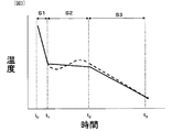
[図1]急冷工程中における合金の温度と経過時間との関係を模式的に示すグラフである。
[図2]本発明の或る実施形態の急冷工程中における合金の温度と経過時間との関係を模式的に示すグラフである。
[図3]本発明の実施に好適に使用可能な装置の構成を示す装置である。
[図4]凝固合金の組織構造を模式的に示す図である。FIG. 1 is a graph schematically showing the relationship between alloy temperature and elapsed time during a rapid cooling process.
FIG. 2 is a graph schematically showing the relationship between the temperature of the alloy and the elapsed time during the rapid cooling step of an embodiment of the present invention.
[FIG. 3] An apparatus showing a configuration of an apparatus that can be suitably used for carrying out the present invention.
FIG. 4 is a diagram schematically showing the structure of a solidified alloy.
1 坩堝
2 タンデッシュ
4 冷却ロール
5 凝固合金
6 ドラム状容器(温度保持手段)
7 モータ1
7 Motor
本発明では、まず、R−T−Q系希土類合金(Rは希土類元素、Tは遷移金属元素、QはB、C、N、Al、Si、およびPからなる群から選択された少なくとも1種の元素)の溶湯を用意する。このR−T−Q系希土類合金は、希土類元素Rとして、Nd、Pr、Y、La、Ce、Pr、Sm、Eu、Gd、Er、Tm、Yb、およびLuからなる群から選択された少なくとも1種の元素RLと、Dy、Tb、およびHoからなる群から選択された少なくとも1種の元素RHとを含有している。In the present invention, first, an RTQ-based rare earth alloy (R is a rare earth element, T is a transition metal element, Q is at least one selected from the group consisting of B, C, N, Al, Si, and P) Prepare a molten metal. This RTQ-based rare earth alloy has at least selected from the group consisting of Nd, Pr, Y, La, Ce, Pr, Sm, Eu, Gd, Er, Tm, Yb, and Lu as the rare earth element R. It contains one element RL and at least one element RH selected from the group consisting of Dy, Tb, and Ho.
次に、上記組成の合金溶湯を急冷して凝固合金を作製するが、本発明者は、このような合金溶湯を急冷して凝固合金を作製する過程において、以下に詳細を説明する「温度保持工程」を実行することにより、凝固合金の粒界相中に位置する元素RHを主相へ移動させ、主相に濃縮できることを見出し、本発明を想到するに到った。Next, a molten alloy having the above composition is rapidly cooled to produce a solidified alloy. The present inventor explained in detail below in the process of rapidly cooling such a molten alloy to produce a solidified alloy. By carrying out the “step”, it was found that the element RH located in the grain boundary phase of the solidified alloy can be moved to the main phase and concentrated in the main phase, and the present invention has been conceived.
以下、図1を参照しながら、本発明で実施する温度保持工程を説明する。 Hereafter, the temperature holding process implemented by this invention is demonstrated, referring FIG.
図1は、急冷工程中における合金の温度と経過時間との関係を模式的に示すグラフである。グラフの縦軸は合金温度であり、横軸は急冷開始からの経過時間である。 FIG. 1 is a graph schematically showing the relationship between the temperature of the alloy and the elapsed time during the rapid cooling process. The vertical axis of the graph is the alloy temperature, and the horizontal axis is the elapsed time from the start of quenching.
図1に示す例では、時刻t0から時刻t1までの期間、合金溶湯の第1冷却工程S1を行い、時刻t1から時刻t2までの期間、温度保持工程S2を行なう。その後、時刻t2から時刻t3まで第2冷却工程S3を実行する。In the example shown in FIG. 1, the period from time t 0 to time t 1, performing a first cooling step S1 of molten alloy, the period from time t 1 to time t 2, the performing temperature holding step S2. Then, run the second cooling process S3 from time t 2 to time t 3.
まず、合金溶湯を回転する冷却ロールの外周面に接触させ、薄帯状の凝固合金を作製する通常のストリップキャスト法を用いて凝固合金を作製する場合を考える。この場合、合金溶湯は時刻t0で冷却ロールの表面に接触し、冷却ロールによる抜熱が開始される。その後、合金溶湯は、回転する冷却ロール上を移動しながら更に急冷され、時刻t1において凝固した状態で冷却ロールの表面から離れることになる。冷却ロールから離れた合金の温度は、通常800〜1000℃程度の範囲にある。従来のストリップキャスト法による場合、冷却ロールを離れた凝固合金の温度は、空冷などの二次冷却により低下し、やがて常温(例えば室温)に達する。図1のグラフでは、破線で示す温度変化が、通常のストリップキャスト法による冷却を行なった場合に得られる時刻t1以降の温度変化を示している。First, let us consider a case in which a solidified alloy is produced using a normal strip casting method in which a molten alloy is brought into contact with the outer peripheral surface of a rotating cooling roll to produce a ribbon-like solidified alloy. In this case, molten alloy is in contact with the surface of the cooling roll at time t 0, heat removal by the cooling roll is started. Then, the molten alloy is further rapidly cooled while moving on a rotating chill roller, solidification state will be away from the surface of the cooling roll at time t 1. The temperature of the alloy separated from the cooling roll is usually in the range of about 800 to 1000 ° C. In the case of the conventional strip casting method, the temperature of the solidified alloy that has left the cooling roll decreases due to secondary cooling such as air cooling, and eventually reaches room temperature (for example, room temperature). In the graph of FIG. 1, the temperature change shown by the dashed lines indicate the temperature variation at time t 1 later obtained when performing cooling by conventional strip casting process.
このような従来の冷却工程に対して、本発明では、時刻t1から時刻t2までの間において、温度保持工程を行なう点に特徴を有している。図1のグラフでは、本発明による合金温度の変化を実線で示している。図1からわかるように、温度保持工程S2が終了する時刻t2以降に行なう第2冷却工程S3では、従来例の破線で示す温度変化と同様に、自然な冷却により、例えば室温程度まで温度を低下させている。For such conventional cooling step, in the present invention, during a period from time t 1 to time t 2, the is characterized in that performing the temperature holding step. In the graph of FIG. 1, the change in the alloy temperature according to the present invention is indicated by a solid line. As can be seen from Figure 1, the second cooling process S3 performed at time t 2 after the temperature holding step S2 is completed, similarly to the temperature change shown by the broken line in the conventional example, by natural cooling, for example a temperature up to about room temperature It is decreasing.
本発明で行なう温度保持工程S2は、合金を700℃以上900℃以下の温度範囲に含まれる所定温度で15秒以上600秒以下の間、保持する。温度保持工程S2を開始する時点において、急冷合金中の粒界には、Dy、Tb、およびHoなどの元素RHは粒界または主相中に略均等に分布していると考えられる。しかし、温度保持工程S2を行なう間に、粒界に存在していたDyなどの元素RHが主相に拡散する一方、主相からは元素RLが粒界に拡散する現象が生じる。700℃以上900℃以下の保持温度においては、凝固合金中の主相は略完全に固体化しているが、粒界は希土類成分が多く融点が低いため、少なくとも一部は液相化している。粒界の一部が液相化した状態にあるとき、粒界からDyなどの元素RHが主相へ活発に拡散すると考えられる。In the temperature holding step S2 performed in the present invention, the alloy is held at a predetermined temperature within a temperature range of 700 ° C. to 900 ° C. for 15 seconds to 600 seconds. At the time when the temperature holding step S2 is started, it is considered that the elements RH such as Dy, Tb, and Ho are distributed substantially uniformly in the grain boundaries or the main phase at the grain boundaries in the quenched alloy. However, during the temperature holding step S2, an element RH such as Dy existing at the grain boundary diffuses into the main phase, while the phenomenon that the element RL diffuses from the main phase into the grain boundary occurs. At a holding temperature of 700 ° C. or more and 900 ° C. or less, the main phase in the solidified alloy is almost completely solidified, but at least a part of the grain boundary is in the liquid phase because of the rare earth component and the low melting point. When a part of the grain boundary is in a liquid phase state, it is considered that an element RH such as Dy actively diffuses from the grain boundary to the main phase.
図4は、凝固合金の組織構造を模式的に示す図である。主相はR2T14Q相から構成され、粒界は希土類元素Rが高濃度に含まれるRリッチ相から構成されている。本発明によれば、図1の実線で示す温度プロファイルに従うように合金を冷却するため、図4に示す粒界にはNdなどの元素RLが相対的に多くなる代わりに、Dyなどの元素RHが主相に濃縮した組織構造が得られ、その結果、保磁力を向上させることが可能になる。FIG. 4 is a diagram schematically showing the structure of the solidified alloy. The main phase is composed of an R 2 T 14 Q phase, and the grain boundary is composed of an R rich phase containing a rare earth element R in a high concentration. According to the present invention, in order to cool the alloy so as to follow the temperature profile shown by the solid line in FIG. 1, instead of the relatively large amount of element RL such as Nd at the grain boundary shown in FIG. A structure in which RH is concentrated in the main phase is obtained, and as a result, the coercive force can be improved.
本発明の温度保持工程S2を行うことにより、図4に示すようにR−T−B系希土類磁石用原料合金の結晶相が粗大化せず、Rリッチ相から主相にDyが拡散される。こうして、主相外郭部にDyが濃縮された層が形成される。このように、温度保持工程S2を行なうことにより、急冷工程によって作製されるR−T−B系希土類磁石用原料合金における主相結晶粒の粒度分布が急峻(シャープ)なものに維持したまま、Dy濃縮層による保磁力向上効果を得ることができる。 By performing the temperature holding step S2 of the present invention, as shown in FIG. 4, the crystal phase of the R-T-B type rare earth magnet raw material alloy is not coarsened, and Dy is diffused from the R-rich phase to the main phase. . Thus, a layer in which Dy is concentrated is formed in the outer portion of the main phase. Thus, by performing the temperature holding step S2, the particle size distribution of the main phase crystal grains in the R-T-B type rare earth magnet raw material alloy produced by the rapid cooling step is maintained to be sharp (sharp), The effect of improving the coercive force by the Dy concentrated layer can be obtained.
なお、Dyが濃縮された層は、主相外郭部の全面に形成される必要は無く、外殻部の一部に形成されていてもよい。Dyが濃縮された層が主相外殻部の一部に形成された場合でも、保磁力向上効果が得られる。 In addition, the layer in which Dy is concentrated does not need to be formed on the entire surface of the main phase outline portion, and may be formed on a part of the outer shell portion. Even when the layer in which Dy is concentrated is formed in a part of the outer shell of the main phase, the effect of improving the coercive force can be obtained.
このようにして得られた凝固合金は、その後、粉砕処理を受けて粉末化される。粉砕工程の前に水素脆化処理を行う場合、粉末表面に粒界相部分が露出しやすいため、粉砕工程を不活性ガス中で行い、しかも、不活性ガス中の酸素濃度を1体積%以下に調節することが好ましい。雰囲気ガス中の酸素濃度が1体積%を超えて高くなりすぎると、微粉砕工程中に粉末粒子が酸化され、希土類元素の一部が酸化物の生成に消費されてしまう。希土類磁石用原料合金粉末中において磁性に寄与しない希土類酸化物が多く生成されると、主相であるR2T14Q系結晶相の存在比率が低下するため、磁石特性が劣化することになる。また、粒界で元素RHの酸化物が生成されやすくなり、主相中の元素RHの濃度が低下する。このような微粉砕は、ジェットミル、アトライタ、ボールミルなどの粉砕装置を用いて行うことができる。なお、ジェットミルによる粉砕は、米国出願09/851,423に開示されている。The solidified alloy thus obtained is then pulverized and pulverized. When hydrogen embrittlement is performed before the pulverization step, the grain boundary phase portion is easily exposed on the powder surface, so the pulverization step is performed in an inert gas, and the oxygen concentration in the inert gas is 1% by volume or less. It is preferable to adjust to. If the oxygen concentration in the atmospheric gas exceeds 1% by volume and becomes too high, the powder particles are oxidized during the pulverization step, and a part of the rare earth element is consumed for the production of oxides. If a large amount of rare earth oxides that do not contribute to magnetism are generated in the raw material alloy powder for rare earth magnets, the abundance ratio of the R 2 T 14 Q crystal phase that is the main phase is lowered, so that the magnet characteristics are deteriorated. . Further, an oxide of the element RH is easily generated at the grain boundary, and the concentration of the element RH in the main phase is lowered. Such fine pulverization can be performed using a pulverizer such as a jet mill, an attritor, or a ball mill. Note that pulverization by a jet mill is disclosed in US application 09 / 851,423.
以下、本発明の好ましい実施形態をより詳細に説明する。 Hereinafter, preferred embodiments of the present invention will be described in more detail.
まず、R−T−Q系希土類合金の溶湯を用意する。希土類元素Rとして、Nd、Pr、Y、La、Ce、Pr、Sm、Eu、Gd、Er、Tm、Yb、およびLuからなる群から選択された少なくとも1種の元素RLと、Dy、Tb、およびHoからなる群から選択された少なくとも1種の元素RHとを含有している。ここで、充分な保磁力向上効果を得るため、希土類元素全体の中に占める元素RHの原子数比率(モル比)を5%以上に設定する。好ましい実施形態において、希土類元素Rの含有量は、合金全体の11原子%以上17原子%以下であり、保磁力向上に寄与する元素RHは、希土類元素R全体の10原子%以上を占める。First, a molten metal of RTQ-based rare earth alloy is prepared. As the rare earth element R, at least one element R L selected from the group consisting of Nd, Pr, Y, La, Ce, Pr, Sm, Eu, Gd, Er, Tm, Yb, and Lu, and Dy, Tb And at least one element RH selected from the group consisting of Ho. Here, in order to obtain a sufficient coercive force improving effect, the atomic ratio (molar ratio) of the element RH in the entire rare earth element is set to 5% or more. In a preferred embodiment, the content of the rare earth element R is 11 atom% or more and 17 atom% or less of the whole alloy, and the element RH contributing to the improvement of the coercive force accounts for 10 atom% or more of the whole rare earth element R.
遷移金属元素Tは、Feを主成分(T全体の50原子%以上)とし、その残部はCoおよび/またはNiなどの遷移金属元素を含んでいてもよい。遷移金属元素Tの含有量は、合金全体の75原子%以上84原子%以下である。 The transition metal element T contains Fe as a main component (50 atomic% or more of the whole T), and the remainder may contain a transition metal element such as Co and / or Ni. The content of the transition metal element T is 75 atomic percent or more and 84 atomic percent or less of the entire alloy.
元素Qは、Bを主成分として含み、正方晶のNd2Fe14B結晶構造中のB(硼素)と置換し得る元素であるC、N、Al、Si、およびPからなる群から選択された少なくとも1種を含んでいても良い。元素Qの含有量は、合金全体の5原子%以上8原子%以下である。The element Q is selected from the group consisting of C, N, Al, Si, and P, which is an element that contains B as a main component and can be substituted for B (boron) in the tetragonal Nd 2 Fe 14 B crystal structure. In addition, at least one kind may be included. The content of the element Q is 5 atomic percent or more and 8 atomic percent or less of the entire alloy.
合金には、上記主要元素のほかに、Ti、V、Cr、Mn、Ni、Cu、Zn、Ga、Zr、Nb、Mo、In、Sn、Hf、Ta、W、およびPbからなる群から選択された少なくとも1種の添加元素Mが添加されていてもよい。 The alloy is selected from the group consisting of Ti, V, Cr, Mn, Ni, Cu, Zn, Ga, Zr, Nb, Mo, In, Sn, Hf, Ta, W, and Pb in addition to the above main elements. At least one kind of additive element M may be added.
上記組成の原料合金の溶湯を、ストリップキャスト装置の冷却ロールの表面と接触させることにより、急冷凝固させる。本実施形態のストリップキャスト装置としては、例えば図3に示す構成を有する装置を用いることができる。 The molten alloy of the raw material alloy having the above composition is rapidly solidified by bringing it into contact with the surface of the cooling roll of the strip casting apparatus. As the strip casting apparatus of the present embodiment, for example, an apparatus having the configuration shown in FIG. 3 can be used.
図3の装置は、傾動可能に指示され、合金溶湯を貯えることができる坩堝1と、坩堝1から供給される合金溶湯を受けるタンデッシュ2と、タンデッシュ2内の合金溶湯を引き上げなげながら急冷する冷却ロール4とを備えている。 The apparatus shown in FIG. 3 is instructed to be tiltable and can cool a
この装置は、回転する冷却ロール4の表面から離れた凝固合金5の薄帯に対して温度保持工程を行なうためのドラム状容器6と、このドラム状容器6を回転駆動するモータ7とを備えている。ドラム状容器6の少なくとも内壁部分における温度は、不図示のヒータなどにより、700℃以上900℃以下の範囲に保たれている。このヒータの出力を調節することにより、凝固合金5の保持温度を変化させることが可能である。温度保持工程においてモータ7を回動させると、凝固合金5の薄帯は例えば長さ数cm程度の鋳片に割れるが、ドラム状容器6の中で攪拌されるため、多数の鋳片は略均等な温度保持処理を受けることになる。温度保持工程が終了した後、ドラム状容器6から凝固合金5の鋳片を取り出し、その後の自然放冷により、更に温度を低下させる。ドラム状容器6から取り出した後の凝固合金5に対しては、できる限り速いレートで冷却することが好ましいため、冷却用のガス(例えば窒素)を吹き付けてもよい。 This apparatus includes a drum-shaped container 6 for performing a temperature maintaining process on a thin strip of the solidified alloy 5 separated from the surface of the rotating cooling roll 4, and a motor 7 that rotationally drives the drum-shaped container 6. ing. The temperature of at least the inner wall portion of the drum-like container 6 is maintained in the range of 700 ° C. or higher and 900 ° C. or lower by a heater (not shown) or the like. The holding temperature of the solidified alloy 5 can be changed by adjusting the output of the heater. When the motor 7 is rotated in the temperature holding step, the ribbon of the solidified alloy 5 is broken into a slab having a length of, for example, about several centimeters. A uniform temperature holding process is performed. After the temperature holding step is completed, the slab of the solidified alloy 5 is taken out from the drum-like container 6 and the temperature is further lowered by subsequent natural cooling. Since it is preferable to cool the solidified alloy 5 after taking out from the drum-shaped container 6 at a rate as fast as possible, a cooling gas (for example, nitrogen) may be blown.
図3に示す装置を用いて本発明を実施する場合、第1冷却工程は、合金溶湯が冷却ロール5の表面と接触した時に開始し、冷却ロール5の表面から離れるまで継続する。第1冷却工程の期間は例えば0.1秒〜10秒程度である。第1冷却工程における冷却速度は、冷却ロールの回転速度(表面周速度)を適切な範囲(例えば1m/秒以上3m/秒以下)に調節することにより、冷却速度は102℃/秒以上104℃/秒以下の範囲に調節する。第1冷却工程で凝固合金の温度を低下しすぎると、その後の温度保持工程を行なうために必要な温度に上昇させるための余分な加熱処理が必要になるので好ましくない。このため、第1冷却工程では、合金温度を700℃以上1000℃以下の範囲までに低下させることが望ましい。When the present invention is carried out using the apparatus shown in FIG. 3, the first cooling step starts when the molten alloy comes into contact with the surface of the cooling roll 5 and continues until it leaves the surface of the cooling roll 5. The period of the first cooling step is, for example, about 0.1 seconds to 10 seconds. The cooling rate in the first cooling step is adjusted to 10 2 ° C./sec or more and 10 to 10 ° C./sec or more by adjusting the rotation speed (surface peripheral speed) of the cooling roll to an appropriate range (for example, 1 m / sec to 3 m / sec). Adjust to the range of 4 ° C / second or less. If the temperature of the solidified alloy is lowered too much in the first cooling step, it is not preferable because an extra heat treatment for raising the temperature to a temperature necessary for the subsequent temperature holding step is required. For this reason, in the first cooling step, it is desirable to lower the alloy temperature to a range of 700 ° C. or higher and 1000 ° C. or lower.
第1冷却工程の後に行なう温度保持工程は、凝固合金5がドラム状容器6の内部に収容されているときに行なわれる。図1に示す例では、時刻t1で第1冷却工程が完了した後、直ちに温度保持工程が開始されているが、図3に示すような装置を用いる場合は、凝固合金5が冷却ロール5から離れてからドラム状容器6の中に移動するまでにかかる時間だけ、温度保持工程の開始時期が遅れる。このように温度保持工程の開始が遅れると、その間に凝固合金5の温度が低下することになるが、その温度が700℃を下回らなければ、問題はない。例えば保持温度を800℃に設定している場合において、温度保持工程開始直前における凝固合金5の温度が750℃に低下していることが起こり得る。このような場合、温度保持工程の少なくとも初期においては、凝固合金5はドラム状容器6に加熱され、750℃から800℃に昇温する。このような昇温が生じたとしても、その間に、Dyなどの元素RHは粒界から主相に拡散するため、保磁力増大の効果を得ることができる。また、温度保持工程は600秒以下の短い期間であるため、結晶粒の粗大化は問題にならない。The temperature holding process performed after the first cooling process is performed when the solidified alloy 5 is accommodated in the drum-shaped container 6. In the example shown in FIG. 1, the temperature holding step is started immediately after the first cooling step is completed at time t 1. However, in the case of using the apparatus shown in FIG. The start time of the temperature holding process is delayed by the time required to move into the drum-like container 6 after leaving the station. If the start of the temperature holding step is delayed in this way, the temperature of the solidified alloy 5 decreases during that time, but there is no problem if the temperature does not fall below 700 ° C. For example, in the case where the holding temperature is set to 800 ° C., the temperature of the solidified alloy 5 immediately before the start of the temperature holding process may be lowered to 750 ° C. In such a case, at least in the initial stage of the temperature holding step, the solidified alloy 5 is heated to the drum-like container 6 and the temperature is raised from 750 ° C. to 800 ° C. Even if such a temperature rise occurs, the element RH such as Dy diffuses from the grain boundary to the main phase during this period, so that the effect of increasing the coercive force can be obtained. Further, since the temperature holding process is a short period of 600 seconds or less, the coarsening of crystal grains does not cause a problem.
このように、本発明における「温度保持工程」とは、凝固合金の温度を厳密に一定レベルに保持する場合のみを意味するのではなく、冷却工程の途中における一定期間、冷却速度を自然放冷の場合よりも意図的に低下させることにより、700℃以上900℃以下の温度範囲を通過する時間を長くすることを広く意味するものとする。 Thus, the “temperature holding step” in the present invention does not mean only when the temperature of the solidified alloy is kept at a strictly constant level, but the cooling rate is allowed to naturally cool for a certain period during the cooling step. By intentionally lowering than in the case of, it is meant broadly to extend the time for passing through the temperature range of 700 ° C. or more and 900 ° C. or less.
一般に、ストリップキャスト法などにより凝固合金を作製する場合、冷却ロールから離れた凝固合金は、大気雰囲気や搬送部材との接触によって抜熱される。このため、本発明における温度保持工程を行なうには、このような自然な冷却(抜熱)に反して熱を凝固合金に供給することが必要になる。この意味で、本発明の「温度保持工程」は、冷却途中に行なう一種の熱処理工程として機能する。 In general, when a solidified alloy is produced by a strip casting method or the like, the solidified alloy separated from the cooling roll is removed by contact with the air atmosphere or a conveying member. For this reason, in order to perform the temperature holding step in the present invention, it is necessary to supply heat to the solidified alloy against such natural cooling (heat removal). In this sense, the “temperature holding step” of the present invention functions as a kind of heat treatment step performed during cooling.
また、凝固合金の温度を一定に保持しようとしても、現実には多少の温度変化が不可避である。例えば、10℃/分以下の冷却速度で生じる緩やかな冷却や、1℃/分以下の昇温速度で生じる極めて緩やかな昇温が生じていても、通常の冷却工程に比べれば略一定の温度に保持されていると認められる。図2は、温度保持工程S2で、合金温度が緩やかに低下している例(実線)や、温度が増減している例(破線)を模式的に示している。このような場合でも、Dyなどの元素RHを粒界から主相に拡散し、保磁力を増大させることが可能である。Even if it is attempted to keep the temperature of the solidified alloy constant, in reality, some temperature change is unavoidable. For example, even when a gentle cooling that occurs at a cooling rate of 10 ° C./min or a very moderate temperature increase that occurs at a heating rate of 1 ° C./min or less occurs, the temperature is substantially constant as compared with a normal cooling process. It is recognized that FIG. 2 schematically shows an example (solid line) in which the alloy temperature is gradually decreased in the temperature holding step S2 and an example (broken line) in which the temperature is increased or decreased. Even in such a case, it is possible to increase the coercive force by diffusing the element RH such as Dy from the grain boundary to the main phase.
温度保持工程が長くなりすぎると、粒成長が生じ、保磁力が低下するおそれがあるため、温度保持の時間は15秒以上600秒以下に設定することが好ましい。 If the temperature holding step becomes too long, grain growth occurs and the coercive force may be lowered. Therefore, the temperature holding time is preferably set to 15 seconds or more and 600 seconds or less.
このような温度保持工程により、Dy、Tb、およびHoからなる群から選択された少なくとも1種の元素RHは、主相に濃縮される。保持温度は、前述したように700℃以上900℃以下の範囲から任意に設定され得るが、700℃〜800℃程度の温度に設定することが好ましい。By such a temperature holding step, at least one element RH selected from the group consisting of Dy, Tb, and Ho is concentrated in the main phase. The holding temperature can be arbitrarily set from the range of 700 ° C. or higher and 900 ° C. or lower as described above, but is preferably set to a temperature of about 700 ° C. to 800 ° C.
温度保持工程後に行う第2冷却工程では、常温(室温程度)まで10℃/秒以上の冷却速度で凝固合金を冷却することが好ましい、比較的大きな冷却速度で合金を冷却することにより、結晶粒の成長を充分に抑制することができる。第2冷却工程は、雰囲気ガスとの接触による自然な冷却で足りる場合もあるが、凝固合金に冷却ガスを吹き付けたり、冷却部材を接触させたりすることにより、積極的な冷却処理を行なっても良い。 In the second cooling step performed after the temperature holding step, it is preferable to cool the solidified alloy to a normal temperature (about room temperature) at a cooling rate of 10 ° C./second or more. By cooling the alloy at a relatively high cooling rate, the crystal grains Can be sufficiently suppressed. In the second cooling step, natural cooling by contact with the atmospheric gas may be sufficient, but even if a positive cooling process is performed by spraying a cooling gas on the solidified alloy or contacting a cooling member. good.
これら一連の工程は、真空または不活性ガス雰囲気中て行なうことが好ましい。図3に示す装置では、第1冷却工程、温度保持工程、および第2冷却工程を大気から仕切られたチャンバー内で実行しているが、第2冷却工程の後半では凝固合金5の温度は相当に低いレベルに低下しているため、大気に接しても酸化などによる品質劣化の問題は少ない。このため、第2冷却工程の一部または全部は、チャンバーの外部で行なっても良い。 These series of steps are preferably performed in a vacuum or an inert gas atmosphere. In the apparatus shown in FIG. 3, the first cooling step, the temperature holding step, and the second cooling step are performed in a chamber partitioned from the atmosphere, but the temperature of the solidified alloy 5 is considerable in the second half of the second cooling step. Therefore, even when exposed to the atmosphere, there is little problem of quality degradation due to oxidation or the like. For this reason, part or all of the second cooling step may be performed outside the chamber.
なお、温度保持工程は、図3に示すような装置によって行なう場合に限定されず、他の方法で行なっても良い。例えば、ストリップキャスト装置の冷却ロールから離れた急冷合金を搬送しながら温度保持工程を行なうようにしても良い。この場合、搬送路上にヒータによる加熱部を配置し、冷却ロールから離れて搬送されてくる凝固合金の自然放熱を抑制すればよい。 The temperature holding step is not limited to the case where it is performed by an apparatus as shown in FIG. 3, and may be performed by another method. For example, the temperature holding step may be performed while conveying a rapidly cooled alloy separated from the cooling roll of the strip casting apparatus. In this case, a heating unit using a heater may be disposed on the transport path to suppress natural heat dissipation of the solidified alloy transported away from the cooling roll.
このようにして作製された急冷合金(ストリップキャスト合金)中には、主相としてR2T14Q相(Rは希土類元素、Tは遷移金属元素、QはB、C、N、Al、Si、およびPからなる群から選択された少なくとも1種の元素)が形成されている。R2T14Q相(主相結晶粒)は、短軸方向サイズ(平均大きさ)が3μm以上10μm以下であり、長軸方向サイズが10μm以上300μm以下の針状結晶(デンドライト)である。In the quenched alloy (strip cast alloy) produced in this way, the R 2 T 14 Q phase (R is a rare earth element, T is a transition metal element, Q is B, C, N, Al, Si) as a main phase. And at least one element selected from the group consisting of P). The R 2 T 14 Q phase (main phase crystal grains) is a needle crystal (dendrites) having a minor axis direction size (average size) of 3 μm to 10 μm and a major axis direction size of 10 μm to 300 μm.
第2冷却工程が終了した時点における(as−spun)凝固合金では、主相であるR2T14Q相における元素RHの濃度がR2T14Q相以外の相(粒界相など)における元素RHの濃度よりも高く、主相への元素RHの濃縮が実現している。In the (as-spun) solidified alloy at the time when the second cooling step is completed, the concentration of the element RH in the main phase R 2 T 14 Q phase is a phase other than the R 2 T 14 Q phase (such as a grain boundary phase). The concentration of element RH in the main phase is higher than the concentration of element RH in FIG.
これは、温度保持工程を行なうことにより、第1冷却工程終了段階において粒界相部分に存在した元素RHが、主相であるR2T14Q相に移動し、R2T14Q相中に濃縮されたことを意味している。こうして、最終的にR2T14Q相における元素RHの濃度は、R2T14Q相以外の相における元素RHの濃度よりも高い凝固合金が得られる。急冷合金中におけるデンドライトの間隔は、温度保持工程の前後で殆んど変化しない。このため、R2T14Q相の短軸方向サイズは、3μm以上10μm以下の範囲のまま、殆んど変化せず、たとえデンドライド結晶が成長したとしても、その成長量は短軸方向にせいぜい1〜2μm程度である。This can be achieved by performing the temperature holding step, the element R H that was present in the grain boundary phase portion in the first cooling step is completed stage is moved to the R 2 T 14 Q phase as the main phase,
本発明では、一旦、室温程度まで冷却した急冷合金を再び加熱することによってDyを拡散させる方法を用いていないため、そのような加熱による結晶粒の粗大化を抑制することができ、Dyなどの希土類元素による保磁力増大効果を効果的に高めることが可能になる。 In the present invention, since the method of diffusing Dy by once again heating the rapidly cooled alloy once cooled to about room temperature is not used, the coarsening of crystal grains due to such heating can be suppressed. The effect of increasing the coercive force due to the rare earth element can be effectively enhanced.
次に、上記の方法によって凝固合金を水素脆化法によって脆化させた後、ジェットミル装置などの粉砕機を用いて粉砕し、微粉末化する。得られた乾式粉末の平均粒径(F.S.S.S.粒径)は、例えば3.0〜4.0μmである。ジェットミル装置では、所定量の酸素が導入された不活性ガスの高速気流を用いて原料合金を粉砕する。不活性ガス中の酸素濃度は1体積%以下に調節することが好ましい。より好ましい酸素濃度は0.1体積%以下である。 Next, after the solidified alloy is embrittled by the hydrogen embrittlement method by the above method, it is pulverized by using a pulverizer such as a jet mill apparatus to make a fine powder. The average particle size (FSSS particle size) of the obtained dry powder is, for example, 3.0 to 4.0 μm. In a jet mill apparatus, a raw material alloy is pulverized using a high-speed air stream of an inert gas into which a predetermined amount of oxygen has been introduced. The oxygen concentration in the inert gas is preferably adjusted to 1% by volume or less. A more preferable oxygen concentration is 0.1% by volume or less.
本発明において、このように粉砕時の雰囲気中酸素濃度を制限する理由は、粒界相から主相へ移動させた元素RHが酸化によって再び粒界相部分に移動・析出しないようにするためである。粉末中に酸素が多く含まれると、Dy、Tb、Hoなどの重希土類元素RHは、酸素と結合してより安定な酸化物を生成する傾向がある。本発明で用いる合金組織では、酸素は主相中よりも粒界相に多く分布するため、主相中の元素RHは再び粒界相へ拡散し、そこで酸化物生成に消費されるものと考えられる。このようにして主相中から元素RHが流出すると、保磁力の十分な向上を実現できないため、粉砕工程および次に説明する焼結工程では、粉末の酸化を適切に抑制することが望ましい。In the present invention, the reason for limiting the oxygen concentration in the atmosphere at the time of pulverization is to prevent the element RH moved from the grain boundary phase to the main phase from moving / precipitating again in the grain boundary phase portion by oxidation. It is. When the powder contains a large amount of oxygen, heavy rare earth elements RH such as Dy, Tb, and Ho tend to combine with oxygen to form a more stable oxide. In the alloy structure used in the present invention, oxygen is distributed more in the grain boundary phase than in the main phase, so that the element RH in the main phase diffuses again into the grain boundary phase, where it is consumed for oxide formation. Conceivable. When the element RH flows out of the main phase in this way, it is not possible to sufficiently improve the coercive force. Therefore, it is desirable to appropriately suppress the oxidation of the powder in the pulverization step and the sintering step described below.
次に、粉体プレス装置を用い、上記粉末を配向磁界中で圧縮し、所望の形状に成形する。こうして得られた粉末成形体を例えば10−4Pa以上106Pa以下の不活性ガス雰囲気下で焼結する。このように酸素濃度を所定レベル以下に制限した雰囲気中にて焼結工程を実行することにより、焼結体(焼結磁石)に含まれる酸素の濃度を0.3質量%以下にすることが望ましい。Next, using a powder press apparatus, the powder is compressed in an orientation magnetic field and formed into a desired shape. The powder compact thus obtained is sintered, for example, in an inert gas atmosphere of 10 −4 Pa to 10 6 Pa. By executing the sintering step in an atmosphere in which the oxygen concentration is limited to a predetermined level or less in this way, the concentration of oxygen contained in the sintered body (sintered magnet) can be reduced to 0.3% by mass or less. desirable.
焼結温度は、主相に濃縮されたDyが長時間の焼結工程時に拡散しないように設定することが好ましい。具体的には、液相が形成される温度(800℃)から、焼結密度が真密度に達する温度までの昇温速度を5℃/mim以上50℃/mim以下の範囲に設定することが好ましい。焼結工程における昇温速度を5℃/mim以上50℃/mim以下の範囲にすると、粉末となった凝固合金の主相に濃縮されたDyが等温保持によって再びRリッチ相に拡散することを抑制することができる。 The sintering temperature is preferably set so that Dy concentrated in the main phase does not diffuse during the long sintering process. Specifically, the rate of temperature increase from the temperature at which the liquid phase is formed (800 ° C.) to the temperature at which the sintered density reaches the true density may be set in the range of 5 ° C./mim to 50 ° C./mim. preferable. When the heating rate in the sintering process is in the range of 5 ° C./mim to 50 ° C./mim, the Dy concentrated in the main phase of the solidified alloy that has become powder diffuses again into the R-rich phase by isothermal holding. Can be suppressed.
水素脆化処理を施すことにより粗粉砕された急冷合金の粉末には、水素が含有されているが、そのような水素を合金粉末から除去するため、焼結前に急冷合金を800℃以上1000℃以下の温度(例えば900℃)で30分から6時間分程度保持しても良い。このような脱水素工程を行なう場合、上記昇温速度での加熱は、脱水素工程の後に行うことになる。 The rapidly-cooled alloy powder coarsely pulverized by the hydrogen embrittlement treatment contains hydrogen, but in order to remove such hydrogen from the alloy powder, the quenched alloy is heated to 800 ° C. or more and 1000 ° C. before sintering. You may hold | maintain for 30 minutes to about 6 hours at the temperature below (for example, 900 degreeC). When performing such a dehydrogenation process, the heating at the above temperature increase rate is performed after the dehydrogenation process.
800℃以上1000℃以下の温度範囲に保持する脱水素工程の後、焼結のための昇温を行なうとき、昇温速度を5℃/mim以上50℃/mim以下の範囲にすると、焼結にともなう粒成長が抑えられるため、等温保持によって向上した保磁力の低下を抑制することもできる。 After the dehydrogenation step of maintaining in the temperature range of 800 ° C. or higher and 1000 ° C. or lower, when the temperature is increased for sintering, if the temperature increase rate is in the range of 5 ° C./mim to 50 ° C./mim, sintering Since the grain growth accompanying it is suppressed, the fall of the coercive force improved by isothermal holding | maintenance can also be suppressed.
なお、焼結後、400℃〜900℃の温度範囲で再加熱処理を行ってもよい。このような再加熱処理を行なうことにより、粒界相を制御し、保磁力を更に高めることができる。 In addition, you may reheat in the temperature range of 400 to 900 degreeC after sintering. By performing such reheating treatment, the grain boundary phase can be controlled and the coercive force can be further increased.
[実施例および比較例]
まず、質量比率で22%Nd−6.0%Pr−3.5%Dy−0.9%Co−1.0%B−残部Fe(その他に不可避的に混入する微量の不純物)の組成を有する合金の溶湯を、単ロールのストリップキャスト法で急冷することにより、上記組成の凝固合金を作製した。[Examples and Comparative Examples]
First, the composition of 22% Nd-6.0% Pr-3.5% Dy-0.9% Co-1.0% B-remaining Fe (a trace amount of impurities inevitably mixed in) in mass ratio The molten alloy was rapidly cooled by a single roll strip casting method to produce a solidified alloy having the above composition.
急冷を開始する直前における溶湯の温度は1350℃であり、ロール表面の周速度は70m/分に設定した。第1冷却工程では、図3に示すようなストリップキャスト装置により、凝固合金の温度700〜800℃程度に低下させた。そして、図3のドラム状容器6により、以下の表1に示す条件で温度保持工程を行なった後、室温まで冷却する第2冷却工程を行なった。 The temperature of the molten metal immediately before starting the rapid cooling was 1350 ° C., and the peripheral speed of the roll surface was set to 70 m / min. In the first cooling step, the temperature of the solidified alloy was lowered to about 700 to 800 ° C. by a strip casting apparatus as shown in FIG. And after performing the temperature holding process on the conditions shown in the following Table 1 with the drum-shaped container 6 of FIG. 3, the 2nd cooling process cooled to room temperature was performed.

なお、サンプルNo.4の比較例では、温度保持工程を行なうことなく、室温まで単調かつ連続的な冷却工程を継続した。 Sample No. In Comparative Example 4, the monotonous and continuous cooling process was continued to room temperature without performing the temperature holding process.
こうして作製されたサンプルNo.1〜4の凝固合金について、電子線を照射して特性X線を検出するEPMA(Electron Probe Micro Analyzer)によるライン分析を行なったところ、Dyの濃度は粒界相よりも主相において相対的に高く、また、NdおよびPrの濃度は主相よりも粒界相において相対的に高いことを確認した。また、BHトレーサにより磁気特性を測定したところ、以下の表2に示す結果が得られた。 Sample no. When the line analysis by EPMA (Electron Probe Micro Analyzer) which detects the characteristic X-rays by irradiating an electron beam was performed on the solidified
表2からわかるように、サンプルNo.1〜3の保磁力HcJは20.1〜20.5kOeであるのに対して、サンプルNo.4の保磁力HcJは19.5kOeである。このように、保持力HcJについては、実施例の値が比較例の値に比べて最大で5%も高いことが確認できた。As can be seen from Table 2, sample no. The
なお、本実施例では、前述のように、微粉砕工程時における酸素濃度を適切な範囲に調節しているため、焼結工程におけるDyの粒界への拡散を抑制するとともに、保磁力の向上を達成することができた。 In this example, as described above, the oxygen concentration during the fine pulverization step is adjusted to an appropriate range, so that diffusion of Dy to the grain boundary in the sintering step is suppressed and the coercive force is improved. Could be achieved.
本発明によれば、保磁力向上目的で添加したDyなど元素RHを、合金溶湯の冷却過程の途中に実行する温度保持工程により、主相中に濃縮することができる。このため、特別な熱処理工程を別途行なうことなく、希少な重希土類元素を有効に活用して保磁力を向上させることが可能になる。According to the present invention, the element RH such as Dy added for the purpose of improving the coercive force can be concentrated in the main phase by the temperature holding step executed during the cooling process of the molten alloy. For this reason, it is possible to improve the coercive force by effectively utilizing a rare heavy rare earth element without separately performing a special heat treatment step.
Claims (13)
前記合金の溶湯を700℃以上1000℃以下の温度まで急冷することによって凝固合金を形成する第1冷却工程と、
前記凝固合金を、700℃以上900℃以下の温度範囲に含まれる温度で15秒以上600秒以下保持する温度保持工程と、
前記凝固合金を400℃以下の温度まで冷却する第2冷却工程と、
を包含し、
前記温度保持工程では、700℃以上900℃以下の温度に加熱された部材で前記急冷凝固合金に熱を供給する、R−T−Q系希土類磁石用原料合金の製造方法。R-T-Q rare earth alloy (R is a rare earth element, T is a transition metal element, Q is at least one element selected from the group consisting of B, C, N, Al, Si, and P) , As the rare earth element R, at least one element R L selected from the group consisting of Nd, Pr, Y, La, Ce, Pr, Sm, Eu, Gd, Er, Tm, Yb, and Lu, and Dy, Preparing a molten alloy containing at least one element R H selected from the group consisting of Tb and Ho;
A first cooling step of forming a solidified alloy by rapidly cooling the molten alloy to a temperature of 700 ° C. or higher and 1000 ° C. or lower;
A temperature holding step for holding the solidified alloy at a temperature included in a temperature range of 700 ° C. to 900 ° C. for 15 seconds to 600 seconds;
A second cooling step for cooling the solidified alloy to a temperature of 400 ° C. or lower;
Including
In the temperature holding step, a method of manufacturing a raw material alloy for an RTQ-based rare earth magnet in which heat is supplied to the rapidly solidified alloy with a member heated to a temperature of 700 ° C. or higher and 900 ° C. or lower.
遷移金属元素Tは全体の75原子%以上84原子%以下、
元素Qは全体の5原子%以上8原子%以下である請求項1に記載の製造方法。Rare earth element R is 11 atomic% or more and 17 atomic% or less of the whole,
Transition metal element T is 75 atom% or more and 84 atom% or less of the whole,
The manufacturing method according to claim 1, wherein the element Q is 5 atomic% or more and 8 atomic% or less of the whole.
前記脆化されたR−T−Q系希土類磁石用原料合金を粉砕する工程と、
を包含するR−T−Q系希土類磁石用原料合金粉末の製造方法。A step of embrittlement of a raw material alloy for RTQ-based rare earth magnet produced by the production method according to claim 1 by a hydrogen embrittlement method;
Crushing the embrittled RTQ-based rare earth magnet raw material alloy;
Of raw material alloy powder for RTQ-based rare earth magnet including
前記成形体を焼結する工程と、
を包含する焼結磁石の製造方法。Preparing a raw material alloy powder for RTQ-based rare earth magnet manufactured by the manufacturing method according to claim 10 or 11, and producing a compact of the powder;
Sintering the molded body;
The manufacturing method of the sintered magnet containing this.
Priority Applications (1)
| Application Number | Priority Date | Filing Date | Title |
|---|---|---|---|
| JP2006519516A JP4692485B2 (en) | 2004-04-30 | 2005-04-27 | Raw material alloy and powder for rare earth magnet and method for producing sintered magnet |
Applications Claiming Priority (4)
| Application Number | Priority Date | Filing Date | Title |
|---|---|---|---|
| JP2004135656 | 2004-04-30 | ||
| JP2004135656 | 2004-04-30 | ||
| JP2006519516A JP4692485B2 (en) | 2004-04-30 | 2005-04-27 | Raw material alloy and powder for rare earth magnet and method for producing sintered magnet |
| PCT/JP2005/008019 WO2005105343A1 (en) | 2004-04-30 | 2005-04-27 | Methods for producing raw material alloy for rare earth magnet, powder and sintered magnet |
Publications (2)
| Publication Number | Publication Date |
|---|---|
| JPWO2005105343A1 JPWO2005105343A1 (en) | 2008-03-13 |
| JP4692485B2 true JP4692485B2 (en) | 2011-06-01 |
Family
ID=35241487
Family Applications (1)
| Application Number | Title | Priority Date | Filing Date |
|---|---|---|---|
| JP2006519516A Active JP4692485B2 (en) | 2004-04-30 | 2005-04-27 | Raw material alloy and powder for rare earth magnet and method for producing sintered magnet |
Country Status (5)
| Country | Link |
|---|---|
| US (1) | US7585378B2 (en) |
| EP (1) | EP1749599B1 (en) |
| JP (1) | JP4692485B2 (en) |
| CN (1) | CN100366363C (en) |
| WO (1) | WO2005105343A1 (en) |
Cited By (1)
| Publication number | Priority date | Publication date | Assignee | Title |
|---|---|---|---|---|
| JP5936688B2 (en) * | 2013-07-31 | 2016-06-22 | 株式会社日立製作所 | Permanent magnet material |
Families Citing this family (33)
| Publication number | Priority date | Publication date | Assignee | Title |
|---|---|---|---|---|
| DK1838887T3 (en) | 2004-12-07 | 2012-07-09 | Hydrexia Pty Ltd | MAGNESIUM ALLOYS FOR HYDROGEN STORAGE |
| JP5063918B2 (en) * | 2006-04-07 | 2012-10-31 | 昭和電工株式会社 | Alloy production equipment |
| US20090035170A1 (en) * | 2007-02-05 | 2009-02-05 | Showa Denko K.K. | R-t-b type alloy and production method thereof, fine powder for r-t-b type rare earth permanent magnet, and r-t-b type rare earth permanent magnet |
| JP4219390B1 (en) * | 2007-09-25 | 2009-02-04 | 昭和電工株式会社 | Alloy production equipment |
| US20100230013A1 (en) * | 2007-12-13 | 2010-09-16 | Showa Denko K.K. | R-t-b alloy, process for production of r-t-b alloy, fine powder for r-t-b rare earth permanent magnets, and r-t-b rare earth permanent magnet |
| CN101872668B (en) * | 2009-04-23 | 2014-06-25 | 北京中科三环高技术股份有限公司 | Sintered NdFeB rear-earth permanent magnet with fine magnetization characteristic and manufacturing method thereof |
| JP5479491B2 (en) * | 2009-12-01 | 2014-04-23 | 株式会社アルバック | Vacuum melting casting equipment |
| JP5059929B2 (en) * | 2009-12-04 | 2012-10-31 | 住友電気工業株式会社 | Magnet powder |
| JP5736653B2 (en) * | 2010-03-09 | 2015-06-17 | Tdk株式会社 | Rare earth sintered magnet and method for producing rare earth sintered magnet |
| JP5059955B2 (en) | 2010-04-15 | 2012-10-31 | 住友電気工業株式会社 | Magnet powder |
| US9196403B2 (en) | 2010-05-19 | 2015-11-24 | Sumitomo Electric Industries, Ltd. | Powder for magnetic member, powder compact, and magnetic member |
| US9862030B2 (en) | 2010-07-02 | 2018-01-09 | Santoku Corporation | Method for producing alloy cast slab for rare earth sintered magnet |
| JP5218869B2 (en) * | 2011-05-24 | 2013-06-26 | 住友電気工業株式会社 | Rare earth-iron-nitrogen alloy material, method for producing rare earth-iron-nitrogen alloy material, rare earth-iron alloy material, and method for producing rare earth-iron alloy material |
| CN102832003A (en) * | 2011-06-17 | 2012-12-19 | 中国科学院宁波材料技术与工程研究所 | Neodymium/ferrum/boron permanent magnet |
| US10497497B2 (en) | 2012-02-02 | 2019-12-03 | Santoku Corporation | R-T-B—Ga-based magnet material alloy and method of producing the same |
| JP5758016B2 (en) * | 2012-02-02 | 2015-08-05 | 中央電気工業株式会社 | Raw material alloy for RTB-Ga magnet and method for producing the same |
| WO2014040525A1 (en) * | 2012-09-12 | 2014-03-20 | 厦门钨业股份有限公司 | Alloy powder for rare-earth magnet, rare-earth magnet manufacturing method and powder pulverizing device |
| CN103050267B (en) * | 2012-12-31 | 2016-01-20 | 厦门钨业股份有限公司 | A kind of based on fine powder heat treated sintered Nd-Fe-B based magnet manufacture method |
| WO2014156181A1 (en) | 2013-03-29 | 2014-10-02 | 中央電気工業株式会社 | Starting-material alloy for r-t-b type magnet and process for producing same |
| WO2014174795A1 (en) * | 2013-04-24 | 2014-10-30 | 中央電気工業株式会社 | Raw material alloy for r-t-b-based magnet |
| CN103219117B (en) * | 2013-05-05 | 2016-04-06 | 沈阳中北真空磁电科技有限公司 | A kind of Double-alloy neodymium iron boron rare earth permanent magnetic material and manufacture method |
| EP3011573B1 (en) | 2013-06-17 | 2020-06-10 | Urban Mining Technology Company, LLC | Magnet recycling to create nd-fe-b magnets with improved or restored magnetic performance |
| CN103377820B (en) | 2013-07-17 | 2015-11-25 | 烟台首钢磁性材料股份有限公司 | A kind of R-T-B-M based sintered magnet and manufacture method thereof |
| CN103871702B (en) * | 2014-03-04 | 2016-04-13 | 山西三益强磁业股份有限公司 | A kind of didymium iron boron nitrogen permanent magnetic material and preparation method |
| CN103871704B (en) * | 2014-03-04 | 2016-03-09 | 南京信息工程大学 | A kind of neodymium iron nitrogen phosphorus permanent magnetic material and preparation method |
| CN103794320B (en) * | 2014-03-04 | 2017-01-18 | 南京信息工程大学 | Neodymium iron nitrogen permanent magnet material and preparation method |
| CN103871701B (en) * | 2014-03-04 | 2016-02-24 | 南京信息工程大学 | A kind of high remanent magnetism praseodymium iron phosphorus permanent magnetic material and preparation method |
| CN103871703B (en) * | 2014-03-04 | 2016-04-13 | 山西三益强磁业股份有限公司 | A kind of praseodymium Nd-Fe-Bo permanent magnet material and preparation method |
| US9336932B1 (en) | 2014-08-15 | 2016-05-10 | Urban Mining Company | Grain boundary engineering |
| RU2578211C1 (en) * | 2014-10-29 | 2016-03-27 | Федеральное государственное унитарное предприятие "Всероссийский научно-исследовательский институт авиационных материалов" (ФГУП "ВИАМ") | Magnetic material for permanent magnets and item made from it |
| CN105374487A (en) * | 2015-12-16 | 2016-03-02 | 南通长江电器实业有限公司 | Corrosion-resistant high-performance rare earth permanent magnet material |
| CN108122653B (en) * | 2017-12-21 | 2019-11-12 | 宁波金轮磁材技术有限公司 | A kind of high-performance neodymium iron boron magnetic materials containing dysprosium and preparation method thereof |
| CN113028842A (en) * | 2021-03-31 | 2021-06-25 | 爱发科真空技术(沈阳)有限公司 | Cooling mechanism and smelting system |
Citations (10)
| Publication number | Priority date | Publication date | Assignee | Title |
|---|---|---|---|---|
| JPH02251345A (en) * | 1989-03-25 | 1990-10-09 | Kobe Steel Ltd | Method for continuously casting magnetic alloy |
| JPH07176413A (en) * | 1993-12-17 | 1995-07-14 | Hitachi Metals Ltd | Manufacture of rare earth element magnet |
| JPH08269643A (en) * | 1995-03-29 | 1996-10-15 | Sumitomo Special Metals Co Ltd | Cast strip for r-fe-b magnetic alloy and its production |
| JPH09170055A (en) * | 1995-12-18 | 1997-06-30 | Showa Denko Kk | Alloy for rare earth magnet, its production and production of permanent magnet |
| JP2000188213A (en) * | 1998-10-14 | 2000-07-04 | Hitachi Metals Ltd | R-t-b sintered permanent magnet |
| JP2002266006A (en) * | 2001-03-12 | 2002-09-18 | Showa Denko Kk | Method for controlling structure of rare-earth- containing alloy, and powder of the alloy and magnet using the same |
| JP2002275598A (en) * | 2001-03-16 | 2002-09-25 | Showa Denko Kk | Normal/defective judgement method for rare earth magnet alloy ingot, manufacturing method, rare earth magnet alloy ingot and rare earth magnet alloy |
| WO2003001541A1 (en) * | 2001-06-22 | 2003-01-03 | Sumitomo Special Metals Co., Ltd. | Rare earth magnet and method for production thereof |
| JP2003188006A (en) * | 2001-12-18 | 2003-07-04 | Showa Denko Kk | Rare earth magnetic alloy sheet, its manufacturing method, sintered rare earth magnetic alloy powder, sintered rare earth magnet, metal powder for bonded magnet, and bonded magnet |
| JP2003226944A (en) * | 2002-02-05 | 2003-08-15 | Sumitomo Special Metals Co Ltd | Sintered magnet using rare earth-iron-boron alloy powder for magnet |
Family Cites Families (18)
| Publication number | Priority date | Publication date | Assignee | Title |
|---|---|---|---|---|
| US5486224A (en) * | 1993-12-28 | 1996-01-23 | Sumitomo Metal Industries, Ltd. | Powder mixture for use in compaction to produce rare earth iron sintered permanent magnets |
| JP3536943B2 (en) * | 1994-12-21 | 2004-06-14 | 昭和電工株式会社 | Alloy for rare earth magnet and method for producing the same |
| JP3201944B2 (en) * | 1995-12-04 | 2001-08-27 | 株式会社三徳 | Rare earth metal containing alloy production system |
| EP0886284B1 (en) * | 1996-04-10 | 2002-10-23 | Showa Denko Kabushiki Kaisha | Cast alloy used for production of rare earth magnet and method for producing cast alloy and magnet |
| CN1188969A (en) * | 1996-11-05 | 1998-07-29 | 三荣化成株式会社 | Preparation method of raw material powder for permanent magnet |
| TW442803B (en) * | 1998-01-23 | 2001-06-23 | Hitachi Metals Ltd | Bond magnet, magnet roll and ferrite powder used thereon, and method of manufacturing them |
| GB9801797D0 (en) * | 1998-01-28 | 1998-03-25 | Rothmans International Ltd | Smoking articles |
| CN1177334C (en) * | 1998-03-27 | 2004-11-24 | 株式会社东芝 | Magnet powder and method for producing the same, and bonded magnet using the same |
| DE19981167T1 (en) * | 1998-05-26 | 2000-08-10 | Hitachi Metals Ltd | Rare earth magnet materials of the nitride type and bond magnets formed therefrom |
| DE69911138T2 (en) | 1998-10-14 | 2004-07-22 | Hitachi Metals, Ltd. | Sintered R-T-B permanent magnet |
| US6403024B1 (en) * | 1999-02-19 | 2002-06-11 | Sumitomo Special Metals Co., Ltd. | Hydrogen pulverizer for rare-earth alloy magnetic material powder using the pulverizer, and method for producing magnet using the pulverizer |
| US6589367B2 (en) * | 1999-06-14 | 2003-07-08 | Shin-Etsu Chemical Co., Ltd. | Anisotropic rare earth-based permanent magnet material |
| JP3231034B1 (en) * | 2000-05-09 | 2001-11-19 | 住友特殊金属株式会社 | Rare earth magnet and manufacturing method thereof |
| WO2002072900A2 (en) * | 2001-03-12 | 2002-09-19 | Showa Denko K.K. | Method for controlling structure of rare earth element-containing alloy, powder material of the alloy and magnet using the same |
| CN1306527C (en) | 2001-12-18 | 2007-03-21 | 昭和电工株式会社 | Rare earth magnetic alloy sheet, its manufacturing method, sintered rare earth magnetic alloy powder, sintered rare earth magnet, metal powder for bonded magnet, and bonded magnet |
| AU2002354227A1 (en) * | 2001-12-19 | 2003-06-30 | Neomax Co., Ltd. | Rare earth element-iron-boron alloy, and magnetically anisotropic permanent magnet powder and method for production thereof |
| AU2003241888A1 (en) * | 2002-05-29 | 2003-12-12 | Santoku Corporation | System for producing alloy containing rare earth metal |
| CN100334662C (en) * | 2002-09-30 | 2007-08-29 | Tdk株式会社 | Method for producing r-t-b based rare earth element permanent magnet |
-
2005
- 2005-04-27 EP EP05736734.4A patent/EP1749599B1/en active Active
- 2005-04-27 WO PCT/JP2005/008019 patent/WO2005105343A1/en active Application Filing
- 2005-04-27 CN CNB2005800008500A patent/CN100366363C/en active Active
- 2005-04-27 US US10/597,853 patent/US7585378B2/en active Active
- 2005-04-27 JP JP2006519516A patent/JP4692485B2/en active Active
Patent Citations (10)
| Publication number | Priority date | Publication date | Assignee | Title |
|---|---|---|---|---|
| JPH02251345A (en) * | 1989-03-25 | 1990-10-09 | Kobe Steel Ltd | Method for continuously casting magnetic alloy |
| JPH07176413A (en) * | 1993-12-17 | 1995-07-14 | Hitachi Metals Ltd | Manufacture of rare earth element magnet |
| JPH08269643A (en) * | 1995-03-29 | 1996-10-15 | Sumitomo Special Metals Co Ltd | Cast strip for r-fe-b magnetic alloy and its production |
| JPH09170055A (en) * | 1995-12-18 | 1997-06-30 | Showa Denko Kk | Alloy for rare earth magnet, its production and production of permanent magnet |
| JP2000188213A (en) * | 1998-10-14 | 2000-07-04 | Hitachi Metals Ltd | R-t-b sintered permanent magnet |
| JP2002266006A (en) * | 2001-03-12 | 2002-09-18 | Showa Denko Kk | Method for controlling structure of rare-earth- containing alloy, and powder of the alloy and magnet using the same |
| JP2002275598A (en) * | 2001-03-16 | 2002-09-25 | Showa Denko Kk | Normal/defective judgement method for rare earth magnet alloy ingot, manufacturing method, rare earth magnet alloy ingot and rare earth magnet alloy |
| WO2003001541A1 (en) * | 2001-06-22 | 2003-01-03 | Sumitomo Special Metals Co., Ltd. | Rare earth magnet and method for production thereof |
| JP2003188006A (en) * | 2001-12-18 | 2003-07-04 | Showa Denko Kk | Rare earth magnetic alloy sheet, its manufacturing method, sintered rare earth magnetic alloy powder, sintered rare earth magnet, metal powder for bonded magnet, and bonded magnet |
| JP2003226944A (en) * | 2002-02-05 | 2003-08-15 | Sumitomo Special Metals Co Ltd | Sintered magnet using rare earth-iron-boron alloy powder for magnet |
Cited By (1)
| Publication number | Priority date | Publication date | Assignee | Title |
|---|---|---|---|---|
| JP5936688B2 (en) * | 2013-07-31 | 2016-06-22 | 株式会社日立製作所 | Permanent magnet material |
Also Published As
| Publication number | Publication date |
|---|---|
| EP1749599A1 (en) | 2007-02-07 |
| CN100366363C (en) | 2008-02-06 |
| WO2005105343A1 (en) | 2005-11-10 |
| US7585378B2 (en) | 2009-09-08 |
| JPWO2005105343A1 (en) | 2008-03-13 |
| EP1749599B1 (en) | 2015-09-09 |
| CN1842385A (en) | 2006-10-04 |
| EP1749599A4 (en) | 2010-08-04 |
| US20080251159A1 (en) | 2008-10-16 |
Similar Documents
| Publication | Publication Date | Title |
|---|---|---|
| JP4692485B2 (en) | Raw material alloy and powder for rare earth magnet and method for producing sintered magnet | |
| CN107871582B (en) | R-Fe-B sintered magnet | |
| CN107871581B (en) | Method for preparing R-Fe-B sintered magnet | |
| JP3909707B2 (en) | Rare earth magnet and manufacturing method thereof | |
| JP4591633B2 (en) | Nanocomposite bulk magnet and method for producing the same | |
| EP0886284A1 (en) | Cast alloy used for production of rare earth magnet and method for producing cast alloy and magnet | |
| JP3267133B2 (en) | Alloy for rare earth magnet, method for producing the same, and method for producing permanent magnet | |
| EP1479787B2 (en) | Sinter magnet made from rare earth-iron-boron alloy powder for magnet | |
| JP2016017203A (en) | Production method for r-t-b-based rear earth sintered magnetic alloy and production method for r-t-b-based rear earth sintered magnet | |
| JP4329318B2 (en) | Rare earth sintered magnet and manufacturing method thereof | |
| JP4879503B2 (en) | Alloy block for RTB-based sintered magnet, manufacturing method thereof and magnet | |
| JPH0931609A (en) | Rare earth magnet alloy and its production | |
| JP2008192903A (en) | Iron-based rare- earth alloy magnet | |
| JP4479944B2 (en) | Alloy flake for rare earth magnet and method for producing the same | |
| JPH08296005A (en) | Alloy for rare earth magnet and its production | |
| JP4442597B2 (en) | Rare earth magnet and manufacturing method thereof | |
| JP4955217B2 (en) | Raw material alloy for RTB-based sintered magnet and method for manufacturing RTB-based sintered magnet | |
| JP3583105B2 (en) | Production method of iron-based rare earth magnet raw material alloy | |
| JP3773484B2 (en) | Nano composite magnet | |
| JP2005288493A (en) | Method and apparatus for producing alloy strip, and method for producing alloy powder | |
| JP6773150B2 (en) | RTB-based rare earth sintered magnet alloy, RTB-based rare earth sintered magnet | |
| JP3815983B2 (en) | Rare earth magnet and manufacturing method thereof | |
| JP2004137582A (en) | Sintered rare earth magnet and its production method | |
| JP2013098319A (en) | METHOD FOR MANUFACTURING Nd-Fe-B MAGNET | |
| JP2003077717A (en) | Rare-earth magnetic alloy agglomeration, its manufacturing method and sintered magnet |
Legal Events
| Date | Code | Title | Description |
|---|---|---|---|
| A131 | Notification of reasons for refusal |
Free format text: JAPANESE INTERMEDIATE CODE: A131 Effective date: 20100706 |
|
| A521 | Request for written amendment filed |
Free format text: JAPANESE INTERMEDIATE CODE: A523 Effective date: 20100901 |
|
| A02 | Decision of refusal |
Free format text: JAPANESE INTERMEDIATE CODE: A02 Effective date: 20101116 |
|
| A521 | Request for written amendment filed |
Free format text: JAPANESE INTERMEDIATE CODE: A523 Effective date: 20101203 |
|
| A911 | Transfer to examiner for re-examination before appeal (zenchi) |
Free format text: JAPANESE INTERMEDIATE CODE: A911 Effective date: 20101210 |
|
| TRDD | Decision of grant or rejection written | ||
| A01 | Written decision to grant a patent or to grant a registration (utility model) |
Free format text: JAPANESE INTERMEDIATE CODE: A01 Effective date: 20110125 |
|
| A01 | Written decision to grant a patent or to grant a registration (utility model) |
Free format text: JAPANESE INTERMEDIATE CODE: A01 |
|
| A61 | First payment of annual fees (during grant procedure) |
Free format text: JAPANESE INTERMEDIATE CODE: A61 Effective date: 20110207 |
|
| FPAY | Renewal fee payment (event date is renewal date of database) |
Free format text: PAYMENT UNTIL: 20140304 Year of fee payment: 3 |
|
| R150 | Certificate of patent or registration of utility model |
Ref document number: 4692485 Country of ref document: JP Free format text: JAPANESE INTERMEDIATE CODE: R150 Free format text: JAPANESE INTERMEDIATE CODE: R150 |
|
| S531 | Written request for registration of change of domicile |
Free format text: JAPANESE INTERMEDIATE CODE: R313531 |
|
| S533 | Written request for registration of change of name |
Free format text: JAPANESE INTERMEDIATE CODE: R313533 |
|
| R350 | Written notification of registration of transfer |
Free format text: JAPANESE INTERMEDIATE CODE: R350 |