JP4689571B2 - Lightweight joining head assembly - Google Patents
Lightweight joining head assembly Download PDFInfo
- Publication number
- JP4689571B2 JP4689571B2 JP2006280417A JP2006280417A JP4689571B2 JP 4689571 B2 JP4689571 B2 JP 4689571B2 JP 2006280417 A JP2006280417 A JP 2006280417A JP 2006280417 A JP2006280417 A JP 2006280417A JP 4689571 B2 JP4689571 B2 JP 4689571B2
- Authority
- JP
- Japan
- Prior art keywords
- head assembly
- joining
- joining head
- motor
- support structure
- Prior art date
- Legal status (The legal status is an assumption and is not a legal conclusion. Google has not performed a legal analysis and makes no representation as to the accuracy of the status listed.)
- Active
Links
- 239000000758 substrate Substances 0.000 claims description 9
- 238000005452 bending Methods 0.000 claims description 8
- 230000003993 interaction Effects 0.000 claims description 3
- 238000003466 welding Methods 0.000 claims description 3
- DMFGNRRURHSENX-UHFFFAOYSA-N beryllium copper Chemical compound [Be].[Cu] DMFGNRRURHSENX-UHFFFAOYSA-N 0.000 claims description 2
- 229910001220 stainless steel Inorganic materials 0.000 claims description 2
- 239000010935 stainless steel Substances 0.000 claims description 2
- 239000007787 solid Substances 0.000 claims 1
- 239000004065 semiconductor Substances 0.000 description 7
- 238000010348 incorporation Methods 0.000 description 4
- 238000013461 design Methods 0.000 description 3
- 230000036316 preload Effects 0.000 description 3
- 238000000034 method Methods 0.000 description 2
- 238000012545 processing Methods 0.000 description 2
- 239000000853 adhesive Substances 0.000 description 1
- 230000001070 adhesive effect Effects 0.000 description 1
- 230000009286 beneficial effect Effects 0.000 description 1
- 230000008901 benefit Effects 0.000 description 1
- 238000006243 chemical reaction Methods 0.000 description 1
- 238000011109 contamination Methods 0.000 description 1
- 230000008878 coupling Effects 0.000 description 1
- 238000010168 coupling process Methods 0.000 description 1
- 238000005859 coupling reaction Methods 0.000 description 1
- 238000005336 cracking Methods 0.000 description 1
- 238000011143 downstream manufacturing Methods 0.000 description 1
- 239000000463 material Substances 0.000 description 1
- 238000012986 modification Methods 0.000 description 1
- 230000004048 modification Effects 0.000 description 1
- 238000012544 monitoring process Methods 0.000 description 1
- 238000004806 packaging method and process Methods 0.000 description 1
- 230000008569 process Effects 0.000 description 1
- 230000000284 resting effect Effects 0.000 description 1
- 230000003068 static effect Effects 0.000 description 1
Images


Classifications
-
- H—ELECTRICITY
- H01—ELECTRIC ELEMENTS
- H01L—SEMICONDUCTOR DEVICES NOT COVERED BY CLASS H10
- H01L21/00—Processes or apparatus adapted for the manufacture or treatment of semiconductor or solid state devices or of parts thereof
- H01L21/67—Apparatus specially adapted for handling semiconductor or electric solid state devices during manufacture or treatment thereof; Apparatus specially adapted for handling wafers during manufacture or treatment of semiconductor or electric solid state devices or components ; Apparatus not specifically provided for elsewhere
- H01L21/67005—Apparatus not specifically provided for elsewhere
- H01L21/67011—Apparatus for manufacture or treatment
- H01L21/67144—Apparatus for mounting on conductive members, e.g. leadframes or conductors on insulating substrates
-
- H—ELECTRICITY
- H01—ELECTRIC ELEMENTS
- H01L—SEMICONDUCTOR DEVICES NOT COVERED BY CLASS H10
- H01L21/00—Processes or apparatus adapted for the manufacture or treatment of semiconductor or solid state devices or of parts thereof
- H01L21/67—Apparatus specially adapted for handling semiconductor or electric solid state devices during manufacture or treatment thereof; Apparatus specially adapted for handling wafers during manufacture or treatment of semiconductor or electric solid state devices or components ; Apparatus not specifically provided for elsewhere
- H01L21/683—Apparatus specially adapted for handling semiconductor or electric solid state devices during manufacture or treatment thereof; Apparatus specially adapted for handling wafers during manufacture or treatment of semiconductor or electric solid state devices or components ; Apparatus not specifically provided for elsewhere for supporting or gripping
- H01L21/6838—Apparatus specially adapted for handling semiconductor or electric solid state devices during manufacture or treatment thereof; Apparatus specially adapted for handling wafers during manufacture or treatment of semiconductor or electric solid state devices or components ; Apparatus not specifically provided for elsewhere for supporting or gripping with gripping and holding devices using a vacuum; Bernoulli devices
Landscapes
- Engineering & Computer Science (AREA)
- Physics & Mathematics (AREA)
- Condensed Matter Physics & Semiconductors (AREA)
- General Physics & Mathematics (AREA)
- Manufacturing & Machinery (AREA)
- Computer Hardware Design (AREA)
- Microelectronics & Electronic Packaging (AREA)
- Power Engineering (AREA)
- Die Bonding (AREA)
- Adhesives Or Adhesive Processes (AREA)
- Wire Bonding (AREA)
Description
本発明は、例えば、ダイ・ボンディング機のためのピックアンドプレイス工具を保持するために使用する接合ヘッド組立体に関する。 The present invention relates to a joining head assembly used, for example, to hold a pick and place tool for a die bonding machine.
半導体パッケージングの間、半導体チップ又はダイは、通常、処理のための基板又は担持体上に装着される。半導体ダイは基板の表層上に直に配置することができるか、あるいは、例えば、複数のダイを積み重ねた構成体のように他のダイ上に配置することができる。基板又は他のダイへの半導体ダイの接続の後、デバイスは、通常、下流の工程において封止される。 During semiconductor packaging, semiconductor chips or dialog are usually mounted on a substrate or carrier for processing. The semiconductor dialog Do can be directly disposed on the surface of the substrate, or, for example, can be arranged on the other of the die as configuration adult stacked a plurality of dies. After the semiconductor die connected to the substrate or other die, the device is usually sealed in a downstream process.
ダイ・ボンディング機は、これら半導体ダイ(これらは、通常、ウェーハから切断される)をピックアップし、その後、基板、キャリア又は他のダイ上にこれらを配置するために使用される。こうしたダイ・ボンディング機は、これらピックアンドプレイス・プロセスで使われるダイピック及びダイ接合ツールを保持して位置決めする接合ヘッド組立体を具備する。 Die bonding machines, these semi-conductor dialog (which are usually is the cut from the wafer) to pick up, then, it is used to place these substrates, onto a carrier, or other dialog. Such die bonding machine comprises a bonding head assembly for holding and positioning Daipikku and die bonding tool used in this Rapi click-and-place process.
寸法が益々小さくなっている半導体ダイの導入により、ダイ・ボンディング機に対する要求はより厳しくなっている。他の考慮すべき問題の中には、より小さく及び/又はより薄いダイは割れ易く、取り扱いにおける、より細かな注意を必要とする。現在のダイボンディング・システムは、徐々にこれら要求に対処することができなくなっていっている。 With the introduction of semiconductor dialog dimensions becomes beneficial s small fence, request against the die bonding machines have become more stringent. Among other considerations, smaller and / or thinner dies are more prone to cracking and require more care in handling . Current of die bonding system has became not be able to cope with gradually this RaKaname required.
図1は、ダイボンダーに使用する慣用の接合ヘッド100の側断面図である。この接合ヘッドは、通常、支持構造体104によって担持される接合本体102を備える。接合本体102は、支持構造体104を上下させることによって鉛直軸線に沿って移動するように駆動可能であるとともに、調節可能なバネ・ポスト106を介して支持構造体104に取り付けられており、このバネ・ポスト106は、調節可能なバネ・ポスト106と接合本体102との間に予圧ばね108を更に備えている。予圧ばね108は、接合ヘッド100が待機位置にあるときには、支持構造体104に向けて接合本体102を付勢する。★更に、接合本体102と支持構造体104との間の相対移動は、シャフト112に沿って可動なケージ軸受110によって案内される。
Figure 1 is a side sectional view of a
接合本体102はピックアンドプレイス・ツールを保持し、このピックアンドプレイス・ツールは、ピックアップ位置からダイをピックし、次いで、これらダイを配置位置に配置する及び/又は接合するように作動可能である。ピックアンドプレイス・ツール114は、通常、コレット組立体の形態をしている。ダイが真空吸引を使用してピックされる場合には、ピックアンドプレイス・ツール114に接続された真空出口116が使用される。図1において、ピックアンドプレイス・ツール114によって保持されたダイ118は基板120上に配置されている。ダイ118は、接着剤又は他の手段を使用して基板120に装着することができる。接合本体102の端部の接触センサ122は、待機中には支持構造体104の一部と接触している。支持構造体104が下方に移動するにつれてピックアンドプレイス・ツール114が更に下方に移動しないようにする際には、接触センサ122は支持構造体104との接触から解放される。接触センサ122の解放は、ピックアンドプレイス・ツール114の接触が相対的に固定された表面で為され、従って、基板120を有するダイ118の表面で為されるということを示す。支持構造体104の更なる下降は、予圧ばね108によって働く力によって接合力をダイ118に与える。
この慣用の接合ヘッドの設計においては、ダイとの接触は、接触センサ122を使用して検出される。上述した接合ヘッドに含まれる全移動質量は約17グラムである。こうした大きな浮動質量の欠点は、比較的高い衝撃力が、ピックアンドプレイス・ツール114からダイ118上に与えられることである。これは、ピックアンドプレイス・ツール114の短寿命並びに不定期に生じるダイクラックの両方をもたらす場合がある。基板120上へのダイ配置の間のサーチ速度が、衝撃力を減らすために遅くされる場合、マイナス面は機械のスループットが実質的に減少されるということである。ケージ軸受110とシャフト112との間の摩擦力は、これらケージ軸受とシャフトとの相対移動を調和させなくするのに要する力を生じさせるので、調和の取れた性能はケージ軸受110の静止摩擦力によって更に制限される。さらに、接触センサ122の使用は、例えば、汚染及び消耗のような接触センサ自体に関する問題をもたらす場合がある。上述した慣用の接合ヘッド100と比べて、より軽く、且つ、より信頼し得る接合ヘッドを開発する要望が存在する。
In this conventional bonding head design, contact with the die is detected using a
従って、従来技術と比較して、より軽量であり、かつ少なくとも慣用の接合ヘッドの幾つかの上記不利な点を回避しようとする接合ヘッドを提供しようとすることが本発明の目的である。 Accordingly, it is an object of the present invention to provide a joining head that is lighter than the prior art and at least tries to avoid some of the above disadvantages of conventional joining heads.
従って、本発明は、接合ヘッド組立体であって、接合ツールを装着するための接合本体と、前記接合ヘッド組立体を異なる位置に移動させるために駆動可能に形状構成された支持構造体と、前記支持構造体に対する移動の間に前記接合本体を撓み可能に支持するための、前記接合本体を前記支持構造体に結合する、少なくとも1つの平面に実質的に沿って配置された撓み要素と、少なくとも1つの前記平面に実質的に直角に延在する軸線に沿って、前記接合本体を前記支持構造体に対して移動するように作動可能な、前記支持構造体に連結されたモータと、を備える接合ヘッド組立体を提供する。 Accordingly, the present invention provides a joining head assembly, a joining body for mounting a joining tool , a support structure configured to be drivable to move the joining head assembly to a different position, wherein for possible to support flex the joint body during movement relative to the support structure, coupling the joint body to the support structure, the flexure elements arranged substantially along at least one plane, along at least one of said axis substantially perpendicular extending plane, operable to move against the joint body to the support structure, and a motor coupled to the support structure A joining head assembly is provided.
本発明の好ましい実施例を例示する添付の図面を参照することで本発明を更に詳細に記載する。図面及び関連した説明の特殊性は、特許請求の範囲の各請求項に記載の本発明の広義の解釈の一般性に代わるものとして理解されるべきではない。 The invention will now be described in further detail with reference to the accompanying drawings, which illustrate preferred embodiments of the invention. Particularity of the drawings and the related description is not a Rubeki be understood as an alternative to the generality of the broad interpretation of the invention as set forth in the following claims.
本発明による接合ヘッド組立体の好ましい実施形態の例を添付の図面を参照して記載する。 Examples of preferred embodiments of the bonding head assembly according to the present invention will be described with reference to the accompanying drawings.
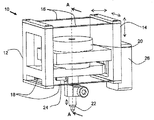
図2は、本発明の好ましい実施形態によるダイボンダーのための接合ヘッド組立体10の等角図である。接合ヘッド組立体は、支持構造体14に対する移動中に接合本体12を撓み可能に支持するための、例えば2組の撓み部材16、18のような撓み要素によって支持構造体14に連結される接合本体12を備える。撓み部材16、18は好ましくは2つの平面に沿って配置され、1つの撓み部材16は接合本体12の上部に向けて装着され、そして、他の撓み部材18は接合本体12の底部に向けて装着される。第1及び第2の平面は互いに対して平行に配置される。あるいは、撓み部材を1つの平面だけに沿って配置するように、1組の撓み部材を使用することができるが、これは、横方向の剛性及び回転剛性が低くなる結果に帰着する場合がある。
Figure 2 is an isometric view of a
コレット22の形態をした接合ツールは、接合本体12に装着され、かつ接合本体122と共に移動可能に構成される。接合ツールは、ダイ・ピックアンドプレイス・ツールまたはダイ接合ツールとし得る。移動を接合本体12及びコレット22に直に与えるように形状構成された、好ましくはボイスコイルモータ20であるモータは、支持構造体14に装着される。接合本体12は、ボイスコイルモータ20によって、撓み部材16 、18が配置された平面に略直角に延在する軸線に沿って上下に駆動可能であり、これに応じてコレット22を駆動する。真空出口24はコレット22に流体連結されて該コレットが真空吸引力によって半導体ダイのピックアップを可能にする。さらに、エンコーダ26が支持構造体に好都合に装着されており、接合本体12の移動を監視している。
A joining tool in the form of a
支持構造体14は、ダイピック位置とダイ接合位置との間のような異なる位置に接合ヘッド組立体10を移動させるためのモータ(図示せず)によって駆動可能に形状構成されている。支持構造体14は、通常、コレット22がボイスコイルモータ20によって更に駆動されて、ダイをピックアップ又は接合する前に、所望の位置上に接合ヘッド組立体10を位置づけるように駆動される。表面に向かって上下にのみ駆動可能に形状構成される接合本体12及びコレット22とは対照的に、支持構造体14は、直交座標系3つの軸線全てに沿って駆動可能に構成されており、所望の場所に亘って該コレット22を配置する。
The
図3は、その中間位置又は待機位置にある接合ヘッド組立体10の、図2の線A−Aに沿って切断した側断面図である。この図においては、ボイスコイルモータ20は、磁気回路を構成するための、支持構造体14に装着された永久磁石26のような磁気回路構成要素と、接合本体12に装着されたボイスコイル28を備えるボイスコイル構成要素とを備えていることが理解できる。そうではなく、永久磁石26を接合本体12に装着することができ、その場合には、ボイスコイル28を支持構造体14に装着することができることが理解される。ボイスコイル28は、電磁相互作用によって接合本体12を駆動させるために磁石26に対して移動可能に適用される。この待機位置においては、撓み部材16、18の方向は、比較的水平である。より大きな剛性を図るために、撓み部材16、18は、ボイスコイルモータ20の対向する両側に配置されている。
FIG. 3 is a side cross-sectional view of the
ボイスコイルモータ20からの駆動力は、撓み部材16、18が配置され、かつこれら撓み部材16、18の中間点を通過する平面に直交する平面に位置するように配置されることが好ましい。コレット22及びボイスコイルモータ20、及びこれによる作用力は、撓み部材16、18の位置に対して実質的に中央に位置し、かつ、撓み部材16、18のそれぞれの側面から実質的に等距離にある点に留意すべきである。このことは、鉛直以外の方向の撓み部材16、18の撓みを制限することによって移動の精度を高める。コレット22は、好ましくはボイスコイルモータ20がコレット22と同軸であるように装着され、これにより、モータの実効力がコレット22を直接通過する。
Driving force from the
図4は、図3による接合ヘッド組立体10の、ダイ30をピックアップするための下向きストロークの間における側断面図である。電流がボイスコイル28を通じて流され、ボイスコイル28が電磁相互作用によって磁石26に対して移動される。この場合、ボイスコイル28は磁石26から離間する方向に移動し、これにより、表面32に載っているダイ30に向かって下向きにコレット22を突出させる。
4, the
接合本体12が支持構造体14に対して移動する際に、この接合本体12の移動はダイ30の方向に撓み部材16、18を撓ませる。好ましくは、支持構造体14は、この移動の間中、相対的に静止したままである。また、エンコーダ26は、接合本体12に連結されたスケール27上のマーキングを参照することによって、接合本体12によって移動された距離を監視し得る。接合本体12の移動の監視は、コレット22の能動的な駆動を促進する。コレット22がダイ30に十分接近するか又はダイ30に接触すると、真空吸引を真空出口24を通じて作動することができ、この真空吸引力によってダイ30を保持する。
When joining the
この形状構成のボイスコイルモータ20を使用することの他の利点は、コレット22の下向き移動中のコレット22とダイ30との間の接触がボイスコイル28によって担持される電流の所定のレベルより高い急激なサージによって検出可能であることである。最初に、ボイスコイル28の電流は、撓み部材16、18の抵抗に打ち勝つのに十分であることを必要とするのみである。しかしながら、コレット22が相対的に固定された表面32に静止しているダイ30に接触すると、電流のサージがコレット22から生じ、表面32からの反力を克服しようとする。したがって、コレット22とダイ30との間の接触が、従来技術の別個の接触センサを用いずに検出可能である。
Another advantage of using the
図5は、図3による接合ヘッド組立体10の、ダイ30がピックアップされ、かつ他の位置にまさに移動しようとしているときの、上向きストロークの間の側断面図である。これを達成するために、ボイスコイル28の電流は、コレット22を下降させるために使用される電流に対して反対方向に流されて、ボイスコイル28が磁石26に向かう方向に移動する。これは、コレット22を、ダイ30を保持しつつ上向きに後退させ、このことがダイを表面32から持ち上げる。
5, the
接合本体12が上向きに移動する際に、撓み部材16、18もまた表面32から離間する方向に上向きに撓む。コレット22がダイ30の配置のために該ダイ30を保持している間に、接合ヘッド組立体10は配置位置に移動することができる。
When joining the
図6は、本発明の好ましい実施例による接合ヘッド組立体10に組み込むのに適した、平らな撓み部材16a、18aの実施例の等角図である。平らな撓み部材16a、18aは、同一平面上に配置され、かつ略長方形状又は略正方形状に固定された、4つの可撓性アーム36から形成されている。装着される際に、接合本体12と支持構造体14との間に延在する可撓性アーム36のうちの2つは互いから離間しているように示されている。撓み部材は、ステンレス鋼又はベリリウム銅を含む、いずれの材料からも作ることができる。装着穴38が、可撓性アームを接合本体12又は支持構造体14に適切に装着するために、可撓性アーム36それぞれの隅部に形成されている。
Figure 6 is suitable for incorporation into the
図7は、本発明の好ましい実施例による接合ヘッド組立体10に組み込むのに適した翼付撓み部材16b、18bの実施例の等角図である。この設計は平らな撓み部材16a、18bの設計に類似しているが、翼付フランジ40が追加されている。これら翼付フランジ40は、可撓性アーム36の少なくとも2つの側面に沿って好ましくは形成され、かつ撓み部材16b、18bの平面に対して垂直に外方に延在している。これら翼付フランジ40は、撓み部材16b、18bの平面に平行な横方向移動42並びに翼付フランジ40に対して平行に延びる軸線回りの回転移動44に対する翼付撓み部材16b、18bにおける横方向及び捩り剛性を高めさせる。翼付撓み部材16b、18bの移動は、翼40の平面に対して本質的に平行な方向にのみ行わせることができる。さらに、翼付フランジ40は、撓み部材16b、18bの座屈を回避させる。上述の内容にもかかわらず、上述した記載は本発明とともに有益に使用することのできる撓み部材16、18の実例にしかすぎず、この記載は排他的であることを意味するものではないことが理解されるべきである。
Figure 7 is an isometric view of a preferred embodiment
本発明の好ましい実施例に記載されている撓み部材の使用が接合ヘッド組立体の重量を減少させ、これにより接合ヘッド組立体は軽くなるということが理解される。このような接合ヘッド組立体10に対して5グラム未満の重量が、慣用の接合ヘッド100に対する17グラムまでの重量と比較して、達成可能である。より軽い接合ヘッド組立体によって、ピックアンドプレースされるダイへの衝撃が、機械の処理能力を減少させることなく、減少される。
It will be appreciated that the use of the flexure members described in the preferred embodiment of the present invention reduces the weight of the joining head assembly, thereby reducing the joining head assembly . Weight of such less than 5 grams with respect to joining the
さらに、ボイスコイルモータ20の駆動力を撓み部材の平面に垂直であり、かつこれらの平面の中央点を通過する平面に位置するように配置し得るので、撓み部材16、18の対称的な負荷が保証される。また、ボイスコイルモータ20は接合ツール又はコレット22と同軸であり、その結果、モータの力は、この力を撓み部材16、18を通じて中継させること無く、コレットの軸を通じて直接伝えられる。この方法は、撓み部材16、18の座屈による故障の危険性を回避するのに役立つ。
Further, since the driving force of the
本願明細書に記載された本発明は、変形、変更及び/又は特に記載された以外の加入を受け入れる余地を有し、本発明が前記記載の精神及び範囲内に入る全ての変形、変更及び/又は加入を含むことを理解すべきである。 The present invention has been described herein, variations, has a room to accept subscription other than those changes and / or in particular wherein, all modifications to which the present invention fall within the spirit and scope of the described, changes and / Or it should be understood to include subscription.
10 接合ヘッド組立体
12 接合本体
14 支持構造体
16、18 屈曲要素
16a、18a 屈曲要素
16b、18b 屈曲要素
20 ボイスコイルモータ
22 コレット
24 真空出口
26 エンコーダ、磁石
28 ボイスコイル
30 ダイ
32 表面
36 屈曲アーム
38 装着穴
40 翼付フランジ
42 横方向移動
44 回転移動
DESCRIPTION OF
Claims (14)
ダイを基板に接合するための接合ツールと、
該接合ツールを装着している接合本体と、
前記接合ヘッド組立体を異なる位置に移動するよう駆動されるように形状構成された支持構造体と、
少なくとも1つの平面に実質的に沿って配置されているとともに、前記接合本体と前記支持構造体とに取り付けられた撓み部材であって、前記支持構造体に対する前記接合本体の移動の間、前記接合本体を撓み可能に支持するように作動可能である撓み部材と、
前記支持構造体に連結されたモータであって、前記少なくとも1つの平面に実質的に垂直に延在する軸線に沿って前記接合本体を前記支持構造体に対して移動させるよう駆動するように作動可能であるとともに、前記接合ツールと同軸に配置されて前記モータからの実効力を前記接合ツールへ直接伝えるモータと、
を備える接合ヘッド組立体。 A joining head assembly comprising:
A bonding tool for bonding the die to the substrate;
A joining body on which the joining tool is mounted;
A support structure shaped and configured to be driven to move the joining head assembly to a different position;
A flexure member disposed substantially along at least one plane and attached to the joint body and the support structure, wherein the joint is moved during movement of the joint body relative to the support structure. A flexure member operable to flexibly support the body;
A motor coupled to the support structure and operative to drive the joint body relative to the support structure along an axis extending substantially perpendicular to the at least one plane; A motor that is disposed coaxially with the welding tool and transmits the effective force from the motor directly to the welding tool,
A joining head assembly comprising:
ボイスコイル構成要素と、
電磁相互作用を行うように形状構成された磁気回路構成要素と、
を有するボイスコイルモータを備え、
前記ボイスコイル構成要素と前記磁気回路構成要素とのうちの一方の構成要素は前記接合本体に装着され、他方の構成要素は前記支持構造体に装着される、請求項1に記載の接合ヘッド組立体。 The motor is
A voice coil component;
A magnetic circuit component shaped and configured to perform electromagnetic interaction;
A voice coil motor having
The joining head assembly according to claim 1, wherein one of the voice coil component and the magnetic circuit component is attached to the joining body, and the other component is attached to the support structure. Solid.
Applications Claiming Priority (2)
| Application Number | Priority Date | Filing Date | Title |
|---|---|---|---|
| US11/250,270 | 2005-10-14 | ||
| US11/250,270 US7303111B2 (en) | 2005-10-14 | 2005-10-14 | Lightweight bondhead assembly |
Publications (3)
| Publication Number | Publication Date |
|---|---|
| JP2007110136A JP2007110136A (en) | 2007-04-26 |
| JP2007110136A5 JP2007110136A5 (en) | 2010-03-11 |
| JP4689571B2 true JP4689571B2 (en) | 2011-05-25 |
Family
ID=37433618
Family Applications (1)
| Application Number | Title | Priority Date | Filing Date |
|---|---|---|---|
| JP2006280417A Active JP4689571B2 (en) | 2005-10-14 | 2006-10-13 | Lightweight joining head assembly |
Country Status (6)
| Country | Link |
|---|---|
| US (1) | US7303111B2 (en) |
| EP (1) | EP1775753A3 (en) |
| JP (1) | JP4689571B2 (en) |
| CN (1) | CN100440426C (en) |
| MY (1) | MY138793A (en) |
| SG (1) | SG131882A1 (en) |
Families Citing this family (18)
| Publication number | Priority date | Publication date | Assignee | Title |
|---|---|---|---|---|
| EP1424884A1 (en) * | 2002-11-29 | 2004-06-02 | Leica Geosystems AG | Method of mounting miniaturised parts on a carrier plate |
| US8293043B2 (en) * | 2006-07-24 | 2012-10-23 | Asm Assembly Automation Ltd | Automatic level adjustment for die bonder |
| US8215648B2 (en) * | 2008-04-21 | 2012-07-10 | Asm Assembly Automation Ltd | Collet mounting assembly for a die bonder |
| CN101635267B (en) * | 2008-07-21 | 2015-03-25 | 旺矽科技股份有限公司 | Device for taking and putting crystalline grain and method thereof |
| US8651159B2 (en) * | 2009-06-12 | 2014-02-18 | Asm Assembly Automation Ltd | Die bonder providing a large bonding force |
| KR200460026Y1 (en) | 2010-02-03 | 2012-04-27 | 리드텍(주) | Die bonding apparatus using non contact driving motor |
| CN102343477B (en) * | 2010-08-02 | 2014-02-19 | 北京中电科电子装备有限公司 | Bonding head device |
| CN102343476B (en) * | 2010-08-02 | 2015-06-03 | 北京中电科电子装备有限公司 | Bonding head device |
| CN102157409A (en) * | 2011-03-17 | 2011-08-17 | 南通富士通微电子股份有限公司 | Bonder |
| JP5813432B2 (en) * | 2011-09-19 | 2015-11-17 | ファスフォードテクノロジ株式会社 | Die bonder and bonding method |
| US8858744B2 (en) | 2011-11-18 | 2014-10-14 | Nike, Inc. | Multi-functional manufacturing tool |
| US20130127193A1 (en) * | 2011-11-18 | 2013-05-23 | Nike, Inc. | Manufacturing Vacuum Tool |
| US9010827B2 (en) | 2011-11-18 | 2015-04-21 | Nike, Inc. | Switchable plate manufacturing vacuum tool |
| US9136243B2 (en) * | 2013-12-03 | 2015-09-15 | Kulicke And Soffa Industries, Inc. | Systems and methods for determining and adjusting a level of parallelism related to bonding of semiconductor elements |
| CN105762099B (en) * | 2014-12-17 | 2019-07-09 | 北京中电科电子装备有限公司 | A kind of chip feed mechanism and die Bonder |
| CN105789101B (en) * | 2014-12-25 | 2020-05-05 | 北京中电科电子装备有限公司 | Chip supply mechanism and chip bonding machine |
| CN106964889A (en) * | 2017-04-28 | 2017-07-21 | 菲斯达排放控制装置(苏州)有限公司 | It is easy to the spot welding device of deep cavity configuration welding |
| CN111573266B (en) * | 2019-02-18 | 2022-01-11 | 宁波舜宇光电信息有限公司 | Loading and unloading equipment for jointed boards of carriers and automatic material buckling machine |
Citations (2)
| Publication number | Priority date | Publication date | Assignee | Title |
|---|---|---|---|---|
| JPH10242175A (en) * | 1997-02-28 | 1998-09-11 | Toshiba Mechatronics Kk | Pellet bonder |
| WO2004064124A1 (en) * | 2003-01-16 | 2004-07-29 | Koninklijke Philips Electronics N.V. | Chip transfer method and apparatus |
Family Cites Families (10)
| Publication number | Priority date | Publication date | Assignee | Title |
|---|---|---|---|---|
| US3209447A (en) * | 1962-03-12 | 1965-10-05 | Aeroprojects Inc | Transducer coupling system |
| DE19724732A1 (en) * | 1997-06-12 | 1998-12-17 | Heidenhain Gmbh Dr Johannes | Length measuring system with a modular scale |
| US6425514B1 (en) * | 1999-11-10 | 2002-07-30 | Asm Technology Singapore Pte Ltd | Force sensing apparatus |
| US6640423B1 (en) * | 2000-07-18 | 2003-11-04 | Endwave Corporation | Apparatus and method for the placement and bonding of a die on a substrate |
| KR100773170B1 (en) * | 2000-09-12 | 2007-11-02 | 언액시스 인터내셔널 트레이딩 엘티디 | Method and apparatus for the mounting of semiconductor chips |
| JP3885867B2 (en) * | 2000-11-29 | 2007-02-28 | 日本電気株式会社 | Wire bonding equipment |
| US6813225B2 (en) * | 2001-08-20 | 2004-11-02 | Asm Assembly Automation Limited | Linear motor driven mechanism using flexure bearings for opto-mechanical devices |
| US20040105750A1 (en) * | 2002-11-29 | 2004-06-03 | Esec Trading Sa, A Swiss Corporation | Method for picking semiconductor chips from a foil |
| US7305757B2 (en) * | 2004-03-15 | 2007-12-11 | Asm Technology Singapore Pte Ltd. | Die ejector system using linear motor |
| US7202956B2 (en) * | 2004-10-08 | 2007-04-10 | Asm Technology Singapore Pte Ltd. | Translation mechanism for opto-mechanical inspection |
-
2005
- 2005-10-14 US US11/250,270 patent/US7303111B2/en active Active
-
2006
- 2006-10-02 EP EP06020698A patent/EP1775753A3/en not_active Withdrawn
- 2006-10-11 CN CNB2006101408244A patent/CN100440426C/en active Active
- 2006-10-11 MY MYPI20064310A patent/MY138793A/en unknown
- 2006-10-12 SG SG200607123-7A patent/SG131882A1/en unknown
- 2006-10-13 JP JP2006280417A patent/JP4689571B2/en active Active
Patent Citations (2)
| Publication number | Priority date | Publication date | Assignee | Title |
|---|---|---|---|---|
| JPH10242175A (en) * | 1997-02-28 | 1998-09-11 | Toshiba Mechatronics Kk | Pellet bonder |
| WO2004064124A1 (en) * | 2003-01-16 | 2004-07-29 | Koninklijke Philips Electronics N.V. | Chip transfer method and apparatus |
Also Published As
| Publication number | Publication date |
|---|---|
| SG131882A1 (en) | 2007-05-28 |
| JP2007110136A (en) | 2007-04-26 |
| EP1775753A2 (en) | 2007-04-18 |
| EP1775753A3 (en) | 2009-01-07 |
| MY138793A (en) | 2009-07-31 |
| CN100440426C (en) | 2008-12-03 |
| US7303111B2 (en) | 2007-12-04 |
| CN1956144A (en) | 2007-05-02 |
| US20070084901A1 (en) | 2007-04-19 |
Similar Documents
| Publication | Publication Date | Title |
|---|---|---|
| JP4689571B2 (en) | Lightweight joining head assembly | |
| EP2711980A1 (en) | Overhead transport carriage | |
| US10340163B2 (en) | Mounting apparatus | |
| WO2007010971A1 (en) | Stage device | |
| US6805616B2 (en) | Wafer planarization apparatus and planarization method thereof | |
| JP2001351930A (en) | Device for transferring die and small part | |
| CN103295932A (en) | Two-shaft drive mechanism and die bonder | |
| TWI231561B (en) | Apparatus for mounting semiconductors | |
| JP5705052B2 (en) | Die bonding equipment | |
| JP2004103653A (en) | Die bonder | |
| JP5762185B2 (en) | Die bonding equipment | |
| JP4496007B2 (en) | Semiconductor mounting equipment | |
| KR101584328B1 (en) | Chip transfer apparatus having an enhanced velocity of chip transfer | |
| KR100310282B1 (en) | Bonding apparatus | |
| JP4954652B2 (en) | Precision parts assembly equipment | |
| JP6186053B2 (en) | Mounting device | |
| JP7543357B2 (en) | Flexible pick arm for pick and place device | |
| CN214956783U (en) | Tie up first solid brilliant device and solid brilliant machine | |
| JP7503712B2 (en) | Parts transfer device | |
| CN212848350U (en) | Die bonding welding head mechanism and system thereof | |
| CN113496931B (en) | Silicon wafer handover device | |
| CN219418976U (en) | Bonded wafer separating device | |
| KR101183093B1 (en) | Bond head module for die bonder | |
| CN114999991A (en) | Piece claw of ultra-precise motion platform | |
| JPH0526740Y2 (en) |
Legal Events
| Date | Code | Title | Description |
|---|---|---|---|
| A977 | Report on retrieval |
Free format text: JAPANESE INTERMEDIATE CODE: A971007 Effective date: 20090909 |
|
| A131 | Notification of reasons for refusal |
Free format text: JAPANESE INTERMEDIATE CODE: A131 Effective date: 20091027 |
|
| A524 | Written submission of copy of amendment under article 19 pct |
Free format text: JAPANESE INTERMEDIATE CODE: A524 Effective date: 20100122 |
|
| A131 | Notification of reasons for refusal |
Free format text: JAPANESE INTERMEDIATE CODE: A131 Effective date: 20100921 |
|
| A521 | Request for written amendment filed |
Free format text: JAPANESE INTERMEDIATE CODE: A523 Effective date: 20101221 |
|
| TRDD | Decision of grant or rejection written | ||
| A01 | Written decision to grant a patent or to grant a registration (utility model) |
Free format text: JAPANESE INTERMEDIATE CODE: A01 Effective date: 20110118 |
|
| A01 | Written decision to grant a patent or to grant a registration (utility model) |
Free format text: JAPANESE INTERMEDIATE CODE: A01 |
|
| A61 | First payment of annual fees (during grant procedure) |
Free format text: JAPANESE INTERMEDIATE CODE: A61 Effective date: 20110216 |
|
| R150 | Certificate of patent or registration of utility model |
Ref document number: 4689571 Country of ref document: JP Free format text: JAPANESE INTERMEDIATE CODE: R150 Free format text: JAPANESE INTERMEDIATE CODE: R150 |
|
| FPAY | Renewal fee payment (event date is renewal date of database) |
Free format text: PAYMENT UNTIL: 20140225 Year of fee payment: 3 |
|
| R250 | Receipt of annual fees |
Free format text: JAPANESE INTERMEDIATE CODE: R250 |
|
| R250 | Receipt of annual fees |
Free format text: JAPANESE INTERMEDIATE CODE: R250 |
|
| R250 | Receipt of annual fees |
Free format text: JAPANESE INTERMEDIATE CODE: R250 |
|
| R250 | Receipt of annual fees |
Free format text: JAPANESE INTERMEDIATE CODE: R250 |
|
| R250 | Receipt of annual fees |
Free format text: JAPANESE INTERMEDIATE CODE: R250 |
|
| R250 | Receipt of annual fees |
Free format text: JAPANESE INTERMEDIATE CODE: R250 |
|
| R250 | Receipt of annual fees |
Free format text: JAPANESE INTERMEDIATE CODE: R250 |
|
| R250 | Receipt of annual fees |
Free format text: JAPANESE INTERMEDIATE CODE: R250 |
|
| R250 | Receipt of annual fees |
Free format text: JAPANESE INTERMEDIATE CODE: R250 |
|
| R250 | Receipt of annual fees |
Free format text: JAPANESE INTERMEDIATE CODE: R250 |
|
| S533 | Written request for registration of change of name |
Free format text: JAPANESE INTERMEDIATE CODE: R313533 |
|
| R350 | Written notification of registration of transfer |
Free format text: JAPANESE INTERMEDIATE CODE: R350 |
|
| R250 | Receipt of annual fees |
Free format text: JAPANESE INTERMEDIATE CODE: R250 |