JP4655723B2 - Vehicle and control method thereof - Google Patents
Vehicle and control method thereof Download PDFInfo
- Publication number
- JP4655723B2 JP4655723B2 JP2005102119A JP2005102119A JP4655723B2 JP 4655723 B2 JP4655723 B2 JP 4655723B2 JP 2005102119 A JP2005102119 A JP 2005102119A JP 2005102119 A JP2005102119 A JP 2005102119A JP 4655723 B2 JP4655723 B2 JP 4655723B2
- Authority
- JP
- Japan
- Prior art keywords
- vehicle speed
- target vehicle
- power
- detected
- brake
- Prior art date
- Legal status (The legal status is an assumption and is not a legal conclusion. Google has not performed a legal analysis and makes no representation as to the accuracy of the status listed.)
- Expired - Fee Related
Links
Images


Classifications
-
- B—PERFORMING OPERATIONS; TRANSPORTING
- B60—VEHICLES IN GENERAL
- B60L—PROPULSION OF ELECTRICALLY-PROPELLED VEHICLES; SUPPLYING ELECTRIC POWER FOR AUXILIARY EQUIPMENT OF ELECTRICALLY-PROPELLED VEHICLES; ELECTRODYNAMIC BRAKE SYSTEMS FOR VEHICLES IN GENERAL; MAGNETIC SUSPENSION OR LEVITATION FOR VEHICLES; MONITORING OPERATING VARIABLES OF ELECTRICALLY-PROPELLED VEHICLES; ELECTRIC SAFETY DEVICES FOR ELECTRICALLY-PROPELLED VEHICLES
- B60L58/00—Methods or circuit arrangements for monitoring or controlling batteries or fuel cells, specially adapted for electric vehicles
- B60L58/10—Methods or circuit arrangements for monitoring or controlling batteries or fuel cells, specially adapted for electric vehicles for monitoring or controlling batteries
- B60L58/12—Methods or circuit arrangements for monitoring or controlling batteries or fuel cells, specially adapted for electric vehicles for monitoring or controlling batteries responding to state of charge [SoC]
- B60L58/14—Preventing excessive discharging
-
- B—PERFORMING OPERATIONS; TRANSPORTING
- B60—VEHICLES IN GENERAL
- B60K—ARRANGEMENT OR MOUNTING OF PROPULSION UNITS OR OF TRANSMISSIONS IN VEHICLES; ARRANGEMENT OR MOUNTING OF PLURAL DIVERSE PRIME-MOVERS IN VEHICLES; AUXILIARY DRIVES FOR VEHICLES; INSTRUMENTATION OR DASHBOARDS FOR VEHICLES; ARRANGEMENTS IN CONNECTION WITH COOLING, AIR INTAKE, GAS EXHAUST OR FUEL SUPPLY OF PROPULSION UNITS IN VEHICLES
- B60K6/00—Arrangement or mounting of plural diverse prime-movers for mutual or common propulsion, e.g. hybrid propulsion systems comprising electric motors and internal combustion engines ; Control systems therefor, i.e. systems controlling two or more prime movers, or controlling one of these prime movers and any of the transmission, drive or drive units Informative references: mechanical gearings with secondary electric drive F16H3/72; arrangements for handling mechanical energy structurally associated with the dynamo-electric machine H02K7/00; machines comprising structurally interrelated motor and generator parts H02K51/00; dynamo-electric machines not otherwise provided for in H02K see H02K99/00
- B60K6/20—Arrangement or mounting of plural diverse prime-movers for mutual or common propulsion, e.g. hybrid propulsion systems comprising electric motors and internal combustion engines ; Control systems therefor, i.e. systems controlling two or more prime movers, or controlling one of these prime movers and any of the transmission, drive or drive units Informative references: mechanical gearings with secondary electric drive F16H3/72; arrangements for handling mechanical energy structurally associated with the dynamo-electric machine H02K7/00; machines comprising structurally interrelated motor and generator parts H02K51/00; dynamo-electric machines not otherwise provided for in H02K see H02K99/00 the prime-movers consisting of electric motors and internal combustion engines, e.g. HEVs
- B60K6/42—Arrangement or mounting of plural diverse prime-movers for mutual or common propulsion, e.g. hybrid propulsion systems comprising electric motors and internal combustion engines ; Control systems therefor, i.e. systems controlling two or more prime movers, or controlling one of these prime movers and any of the transmission, drive or drive units Informative references: mechanical gearings with secondary electric drive F16H3/72; arrangements for handling mechanical energy structurally associated with the dynamo-electric machine H02K7/00; machines comprising structurally interrelated motor and generator parts H02K51/00; dynamo-electric machines not otherwise provided for in H02K see H02K99/00 the prime-movers consisting of electric motors and internal combustion engines, e.g. HEVs characterised by the architecture of the hybrid electric vehicle
- B60K6/44—Series-parallel type
- B60K6/442—Series-parallel switching type
-
- B—PERFORMING OPERATIONS; TRANSPORTING
- B60—VEHICLES IN GENERAL
- B60K—ARRANGEMENT OR MOUNTING OF PROPULSION UNITS OR OF TRANSMISSIONS IN VEHICLES; ARRANGEMENT OR MOUNTING OF PLURAL DIVERSE PRIME-MOVERS IN VEHICLES; AUXILIARY DRIVES FOR VEHICLES; INSTRUMENTATION OR DASHBOARDS FOR VEHICLES; ARRANGEMENTS IN CONNECTION WITH COOLING, AIR INTAKE, GAS EXHAUST OR FUEL SUPPLY OF PROPULSION UNITS IN VEHICLES
- B60K6/00—Arrangement or mounting of plural diverse prime-movers for mutual or common propulsion, e.g. hybrid propulsion systems comprising electric motors and internal combustion engines ; Control systems therefor, i.e. systems controlling two or more prime movers, or controlling one of these prime movers and any of the transmission, drive or drive units Informative references: mechanical gearings with secondary electric drive F16H3/72; arrangements for handling mechanical energy structurally associated with the dynamo-electric machine H02K7/00; machines comprising structurally interrelated motor and generator parts H02K51/00; dynamo-electric machines not otherwise provided for in H02K see H02K99/00
- B60K6/20—Arrangement or mounting of plural diverse prime-movers for mutual or common propulsion, e.g. hybrid propulsion systems comprising electric motors and internal combustion engines ; Control systems therefor, i.e. systems controlling two or more prime movers, or controlling one of these prime movers and any of the transmission, drive or drive units Informative references: mechanical gearings with secondary electric drive F16H3/72; arrangements for handling mechanical energy structurally associated with the dynamo-electric machine H02K7/00; machines comprising structurally interrelated motor and generator parts H02K51/00; dynamo-electric machines not otherwise provided for in H02K see H02K99/00 the prime-movers consisting of electric motors and internal combustion engines, e.g. HEVs
- B60K6/42—Arrangement or mounting of plural diverse prime-movers for mutual or common propulsion, e.g. hybrid propulsion systems comprising electric motors and internal combustion engines ; Control systems therefor, i.e. systems controlling two or more prime movers, or controlling one of these prime movers and any of the transmission, drive or drive units Informative references: mechanical gearings with secondary electric drive F16H3/72; arrangements for handling mechanical energy structurally associated with the dynamo-electric machine H02K7/00; machines comprising structurally interrelated motor and generator parts H02K51/00; dynamo-electric machines not otherwise provided for in H02K see H02K99/00 the prime-movers consisting of electric motors and internal combustion engines, e.g. HEVs characterised by the architecture of the hybrid electric vehicle
- B60K6/48—Parallel type
-
- B—PERFORMING OPERATIONS; TRANSPORTING
- B60—VEHICLES IN GENERAL
- B60L—PROPULSION OF ELECTRICALLY-PROPELLED VEHICLES; SUPPLYING ELECTRIC POWER FOR AUXILIARY EQUIPMENT OF ELECTRICALLY-PROPELLED VEHICLES; ELECTRODYNAMIC BRAKE SYSTEMS FOR VEHICLES IN GENERAL; MAGNETIC SUSPENSION OR LEVITATION FOR VEHICLES; MONITORING OPERATING VARIABLES OF ELECTRICALLY-PROPELLED VEHICLES; ELECTRIC SAFETY DEVICES FOR ELECTRICALLY-PROPELLED VEHICLES
- B60L15/00—Methods, circuits, or devices for controlling the traction-motor speed of electrically-propelled vehicles
- B60L15/20—Methods, circuits, or devices for controlling the traction-motor speed of electrically-propelled vehicles for control of the vehicle or its driving motor to achieve a desired performance, e.g. speed, torque, programmed variation of speed
- B60L15/2009—Methods, circuits, or devices for controlling the traction-motor speed of electrically-propelled vehicles for control of the vehicle or its driving motor to achieve a desired performance, e.g. speed, torque, programmed variation of speed for braking
- B60L15/2018—Methods, circuits, or devices for controlling the traction-motor speed of electrically-propelled vehicles for control of the vehicle or its driving motor to achieve a desired performance, e.g. speed, torque, programmed variation of speed for braking for braking on a slope
- B60L15/2027—Methods, circuits, or devices for controlling the traction-motor speed of electrically-propelled vehicles for control of the vehicle or its driving motor to achieve a desired performance, e.g. speed, torque, programmed variation of speed for braking for braking on a slope whilst maintaining constant speed
-
- B—PERFORMING OPERATIONS; TRANSPORTING
- B60—VEHICLES IN GENERAL
- B60L—PROPULSION OF ELECTRICALLY-PROPELLED VEHICLES; SUPPLYING ELECTRIC POWER FOR AUXILIARY EQUIPMENT OF ELECTRICALLY-PROPELLED VEHICLES; ELECTRODYNAMIC BRAKE SYSTEMS FOR VEHICLES IN GENERAL; MAGNETIC SUSPENSION OR LEVITATION FOR VEHICLES; MONITORING OPERATING VARIABLES OF ELECTRICALLY-PROPELLED VEHICLES; ELECTRIC SAFETY DEVICES FOR ELECTRICALLY-PROPELLED VEHICLES
- B60L15/00—Methods, circuits, or devices for controlling the traction-motor speed of electrically-propelled vehicles
- B60L15/20—Methods, circuits, or devices for controlling the traction-motor speed of electrically-propelled vehicles for control of the vehicle or its driving motor to achieve a desired performance, e.g. speed, torque, programmed variation of speed
- B60L15/2045—Methods, circuits, or devices for controlling the traction-motor speed of electrically-propelled vehicles for control of the vehicle or its driving motor to achieve a desired performance, e.g. speed, torque, programmed variation of speed for optimising the use of energy
-
- B—PERFORMING OPERATIONS; TRANSPORTING
- B60—VEHICLES IN GENERAL
- B60L—PROPULSION OF ELECTRICALLY-PROPELLED VEHICLES; SUPPLYING ELECTRIC POWER FOR AUXILIARY EQUIPMENT OF ELECTRICALLY-PROPELLED VEHICLES; ELECTRODYNAMIC BRAKE SYSTEMS FOR VEHICLES IN GENERAL; MAGNETIC SUSPENSION OR LEVITATION FOR VEHICLES; MONITORING OPERATING VARIABLES OF ELECTRICALLY-PROPELLED VEHICLES; ELECTRIC SAFETY DEVICES FOR ELECTRICALLY-PROPELLED VEHICLES
- B60L50/00—Electric propulsion with power supplied within the vehicle
- B60L50/10—Electric propulsion with power supplied within the vehicle using propulsion power supplied by engine-driven generators, e.g. generators driven by combustion engines
- B60L50/16—Electric propulsion with power supplied within the vehicle using propulsion power supplied by engine-driven generators, e.g. generators driven by combustion engines with provision for separate direct mechanical propulsion
-
- B—PERFORMING OPERATIONS; TRANSPORTING
- B60—VEHICLES IN GENERAL
- B60L—PROPULSION OF ELECTRICALLY-PROPELLED VEHICLES; SUPPLYING ELECTRIC POWER FOR AUXILIARY EQUIPMENT OF ELECTRICALLY-PROPELLED VEHICLES; ELECTRODYNAMIC BRAKE SYSTEMS FOR VEHICLES IN GENERAL; MAGNETIC SUSPENSION OR LEVITATION FOR VEHICLES; MONITORING OPERATING VARIABLES OF ELECTRICALLY-PROPELLED VEHICLES; ELECTRIC SAFETY DEVICES FOR ELECTRICALLY-PROPELLED VEHICLES
- B60L58/00—Methods or circuit arrangements for monitoring or controlling batteries or fuel cells, specially adapted for electric vehicles
- B60L58/10—Methods or circuit arrangements for monitoring or controlling batteries or fuel cells, specially adapted for electric vehicles for monitoring or controlling batteries
- B60L58/12—Methods or circuit arrangements for monitoring or controlling batteries or fuel cells, specially adapted for electric vehicles for monitoring or controlling batteries responding to state of charge [SoC]
- B60L58/15—Preventing overcharging
-
- B—PERFORMING OPERATIONS; TRANSPORTING
- B60—VEHICLES IN GENERAL
- B60L—PROPULSION OF ELECTRICALLY-PROPELLED VEHICLES; SUPPLYING ELECTRIC POWER FOR AUXILIARY EQUIPMENT OF ELECTRICALLY-PROPELLED VEHICLES; ELECTRODYNAMIC BRAKE SYSTEMS FOR VEHICLES IN GENERAL; MAGNETIC SUSPENSION OR LEVITATION FOR VEHICLES; MONITORING OPERATING VARIABLES OF ELECTRICALLY-PROPELLED VEHICLES; ELECTRIC SAFETY DEVICES FOR ELECTRICALLY-PROPELLED VEHICLES
- B60L7/00—Electrodynamic brake systems for vehicles in general
- B60L7/10—Dynamic electric regenerative braking
- B60L7/14—Dynamic electric regenerative braking for vehicles propelled by ac motors
-
- B—PERFORMING OPERATIONS; TRANSPORTING
- B60—VEHICLES IN GENERAL
- B60W—CONJOINT CONTROL OF VEHICLE SUB-UNITS OF DIFFERENT TYPE OR DIFFERENT FUNCTION; CONTROL SYSTEMS SPECIALLY ADAPTED FOR HYBRID VEHICLES; ROAD VEHICLE DRIVE CONTROL SYSTEMS FOR PURPOSES NOT RELATED TO THE CONTROL OF A PARTICULAR SUB-UNIT
- B60W10/00—Conjoint control of vehicle sub-units of different type or different function
- B60W10/04—Conjoint control of vehicle sub-units of different type or different function including control of propulsion units
- B60W10/06—Conjoint control of vehicle sub-units of different type or different function including control of propulsion units including control of combustion engines
-
- B—PERFORMING OPERATIONS; TRANSPORTING
- B60—VEHICLES IN GENERAL
- B60W—CONJOINT CONTROL OF VEHICLE SUB-UNITS OF DIFFERENT TYPE OR DIFFERENT FUNCTION; CONTROL SYSTEMS SPECIALLY ADAPTED FOR HYBRID VEHICLES; ROAD VEHICLE DRIVE CONTROL SYSTEMS FOR PURPOSES NOT RELATED TO THE CONTROL OF A PARTICULAR SUB-UNIT
- B60W10/00—Conjoint control of vehicle sub-units of different type or different function
- B60W10/04—Conjoint control of vehicle sub-units of different type or different function including control of propulsion units
- B60W10/08—Conjoint control of vehicle sub-units of different type or different function including control of propulsion units including control of electric propulsion units, e.g. motors or generators
-
- B—PERFORMING OPERATIONS; TRANSPORTING
- B60—VEHICLES IN GENERAL
- B60W—CONJOINT CONTROL OF VEHICLE SUB-UNITS OF DIFFERENT TYPE OR DIFFERENT FUNCTION; CONTROL SYSTEMS SPECIALLY ADAPTED FOR HYBRID VEHICLES; ROAD VEHICLE DRIVE CONTROL SYSTEMS FOR PURPOSES NOT RELATED TO THE CONTROL OF A PARTICULAR SUB-UNIT
- B60W20/00—Control systems specially adapted for hybrid vehicles
-
- B—PERFORMING OPERATIONS; TRANSPORTING
- B60—VEHICLES IN GENERAL
- B60W—CONJOINT CONTROL OF VEHICLE SUB-UNITS OF DIFFERENT TYPE OR DIFFERENT FUNCTION; CONTROL SYSTEMS SPECIALLY ADAPTED FOR HYBRID VEHICLES; ROAD VEHICLE DRIVE CONTROL SYSTEMS FOR PURPOSES NOT RELATED TO THE CONTROL OF A PARTICULAR SUB-UNIT
- B60W30/00—Purposes of road vehicle drive control systems not related to the control of a particular sub-unit, e.g. of systems using conjoint control of vehicle sub-units, or advanced driver assistance systems for ensuring comfort, stability and safety or drive control systems for propelling or retarding the vehicle
- B60W30/14—Adaptive cruise control
- B60W30/143—Speed control
-
- B—PERFORMING OPERATIONS; TRANSPORTING
- B60—VEHICLES IN GENERAL
- B60K—ARRANGEMENT OR MOUNTING OF PROPULSION UNITS OR OF TRANSMISSIONS IN VEHICLES; ARRANGEMENT OR MOUNTING OF PLURAL DIVERSE PRIME-MOVERS IN VEHICLES; AUXILIARY DRIVES FOR VEHICLES; INSTRUMENTATION OR DASHBOARDS FOR VEHICLES; ARRANGEMENTS IN CONNECTION WITH COOLING, AIR INTAKE, GAS EXHAUST OR FUEL SUPPLY OF PROPULSION UNITS IN VEHICLES
- B60K1/00—Arrangement or mounting of electrical propulsion units
- B60K1/02—Arrangement or mounting of electrical propulsion units comprising more than one electric motor
-
- B—PERFORMING OPERATIONS; TRANSPORTING
- B60—VEHICLES IN GENERAL
- B60L—PROPULSION OF ELECTRICALLY-PROPELLED VEHICLES; SUPPLYING ELECTRIC POWER FOR AUXILIARY EQUIPMENT OF ELECTRICALLY-PROPELLED VEHICLES; ELECTRODYNAMIC BRAKE SYSTEMS FOR VEHICLES IN GENERAL; MAGNETIC SUSPENSION OR LEVITATION FOR VEHICLES; MONITORING OPERATING VARIABLES OF ELECTRICALLY-PROPELLED VEHICLES; ELECTRIC SAFETY DEVICES FOR ELECTRICALLY-PROPELLED VEHICLES
- B60L2220/00—Electrical machine types; Structures or applications thereof
- B60L2220/10—Electrical machine types
- B60L2220/14—Synchronous machines
-
- B—PERFORMING OPERATIONS; TRANSPORTING
- B60—VEHICLES IN GENERAL
- B60L—PROPULSION OF ELECTRICALLY-PROPELLED VEHICLES; SUPPLYING ELECTRIC POWER FOR AUXILIARY EQUIPMENT OF ELECTRICALLY-PROPELLED VEHICLES; ELECTRODYNAMIC BRAKE SYSTEMS FOR VEHICLES IN GENERAL; MAGNETIC SUSPENSION OR LEVITATION FOR VEHICLES; MONITORING OPERATING VARIABLES OF ELECTRICALLY-PROPELLED VEHICLES; ELECTRIC SAFETY DEVICES FOR ELECTRICALLY-PROPELLED VEHICLES
- B60L2220/00—Electrical machine types; Structures or applications thereof
- B60L2220/10—Electrical machine types
- B60L2220/16—DC brushless machines
-
- B—PERFORMING OPERATIONS; TRANSPORTING
- B60—VEHICLES IN GENERAL
- B60L—PROPULSION OF ELECTRICALLY-PROPELLED VEHICLES; SUPPLYING ELECTRIC POWER FOR AUXILIARY EQUIPMENT OF ELECTRICALLY-PROPELLED VEHICLES; ELECTRODYNAMIC BRAKE SYSTEMS FOR VEHICLES IN GENERAL; MAGNETIC SUSPENSION OR LEVITATION FOR VEHICLES; MONITORING OPERATING VARIABLES OF ELECTRICALLY-PROPELLED VEHICLES; ELECTRIC SAFETY DEVICES FOR ELECTRICALLY-PROPELLED VEHICLES
- B60L2240/00—Control parameters of input or output; Target parameters
- B60L2240/10—Vehicle control parameters
- B60L2240/12—Speed
-
- B—PERFORMING OPERATIONS; TRANSPORTING
- B60—VEHICLES IN GENERAL
- B60L—PROPULSION OF ELECTRICALLY-PROPELLED VEHICLES; SUPPLYING ELECTRIC POWER FOR AUXILIARY EQUIPMENT OF ELECTRICALLY-PROPELLED VEHICLES; ELECTRODYNAMIC BRAKE SYSTEMS FOR VEHICLES IN GENERAL; MAGNETIC SUSPENSION OR LEVITATION FOR VEHICLES; MONITORING OPERATING VARIABLES OF ELECTRICALLY-PROPELLED VEHICLES; ELECTRIC SAFETY DEVICES FOR ELECTRICALLY-PROPELLED VEHICLES
- B60L2240/00—Control parameters of input or output; Target parameters
- B60L2240/10—Vehicle control parameters
- B60L2240/14—Acceleration
-
- B—PERFORMING OPERATIONS; TRANSPORTING
- B60—VEHICLES IN GENERAL
- B60L—PROPULSION OF ELECTRICALLY-PROPELLED VEHICLES; SUPPLYING ELECTRIC POWER FOR AUXILIARY EQUIPMENT OF ELECTRICALLY-PROPELLED VEHICLES; ELECTRODYNAMIC BRAKE SYSTEMS FOR VEHICLES IN GENERAL; MAGNETIC SUSPENSION OR LEVITATION FOR VEHICLES; MONITORING OPERATING VARIABLES OF ELECTRICALLY-PROPELLED VEHICLES; ELECTRIC SAFETY DEVICES FOR ELECTRICALLY-PROPELLED VEHICLES
- B60L2240/00—Control parameters of input or output; Target parameters
- B60L2240/40—Drive Train control parameters
- B60L2240/42—Drive Train control parameters related to electric machines
- B60L2240/421—Speed
-
- B—PERFORMING OPERATIONS; TRANSPORTING
- B60—VEHICLES IN GENERAL
- B60L—PROPULSION OF ELECTRICALLY-PROPELLED VEHICLES; SUPPLYING ELECTRIC POWER FOR AUXILIARY EQUIPMENT OF ELECTRICALLY-PROPELLED VEHICLES; ELECTRODYNAMIC BRAKE SYSTEMS FOR VEHICLES IN GENERAL; MAGNETIC SUSPENSION OR LEVITATION FOR VEHICLES; MONITORING OPERATING VARIABLES OF ELECTRICALLY-PROPELLED VEHICLES; ELECTRIC SAFETY DEVICES FOR ELECTRICALLY-PROPELLED VEHICLES
- B60L2240/00—Control parameters of input or output; Target parameters
- B60L2240/40—Drive Train control parameters
- B60L2240/42—Drive Train control parameters related to electric machines
- B60L2240/423—Torque
-
- B—PERFORMING OPERATIONS; TRANSPORTING
- B60—VEHICLES IN GENERAL
- B60L—PROPULSION OF ELECTRICALLY-PROPELLED VEHICLES; SUPPLYING ELECTRIC POWER FOR AUXILIARY EQUIPMENT OF ELECTRICALLY-PROPELLED VEHICLES; ELECTRODYNAMIC BRAKE SYSTEMS FOR VEHICLES IN GENERAL; MAGNETIC SUSPENSION OR LEVITATION FOR VEHICLES; MONITORING OPERATING VARIABLES OF ELECTRICALLY-PROPELLED VEHICLES; ELECTRIC SAFETY DEVICES FOR ELECTRICALLY-PROPELLED VEHICLES
- B60L2240/00—Control parameters of input or output; Target parameters
- B60L2240/40—Drive Train control parameters
- B60L2240/44—Drive Train control parameters related to combustion engines
- B60L2240/441—Speed
-
- B—PERFORMING OPERATIONS; TRANSPORTING
- B60—VEHICLES IN GENERAL
- B60L—PROPULSION OF ELECTRICALLY-PROPELLED VEHICLES; SUPPLYING ELECTRIC POWER FOR AUXILIARY EQUIPMENT OF ELECTRICALLY-PROPELLED VEHICLES; ELECTRODYNAMIC BRAKE SYSTEMS FOR VEHICLES IN GENERAL; MAGNETIC SUSPENSION OR LEVITATION FOR VEHICLES; MONITORING OPERATING VARIABLES OF ELECTRICALLY-PROPELLED VEHICLES; ELECTRIC SAFETY DEVICES FOR ELECTRICALLY-PROPELLED VEHICLES
- B60L2240/00—Control parameters of input or output; Target parameters
- B60L2240/40—Drive Train control parameters
- B60L2240/44—Drive Train control parameters related to combustion engines
- B60L2240/443—Torque
-
- B—PERFORMING OPERATIONS; TRANSPORTING
- B60—VEHICLES IN GENERAL
- B60L—PROPULSION OF ELECTRICALLY-PROPELLED VEHICLES; SUPPLYING ELECTRIC POWER FOR AUXILIARY EQUIPMENT OF ELECTRICALLY-PROPELLED VEHICLES; ELECTRODYNAMIC BRAKE SYSTEMS FOR VEHICLES IN GENERAL; MAGNETIC SUSPENSION OR LEVITATION FOR VEHICLES; MONITORING OPERATING VARIABLES OF ELECTRICALLY-PROPELLED VEHICLES; ELECTRIC SAFETY DEVICES FOR ELECTRICALLY-PROPELLED VEHICLES
- B60L2240/00—Control parameters of input or output; Target parameters
- B60L2240/40—Drive Train control parameters
- B60L2240/48—Drive Train control parameters related to transmissions
- B60L2240/486—Operating parameters
-
- B—PERFORMING OPERATIONS; TRANSPORTING
- B60—VEHICLES IN GENERAL
- B60L—PROPULSION OF ELECTRICALLY-PROPELLED VEHICLES; SUPPLYING ELECTRIC POWER FOR AUXILIARY EQUIPMENT OF ELECTRICALLY-PROPELLED VEHICLES; ELECTRODYNAMIC BRAKE SYSTEMS FOR VEHICLES IN GENERAL; MAGNETIC SUSPENSION OR LEVITATION FOR VEHICLES; MONITORING OPERATING VARIABLES OF ELECTRICALLY-PROPELLED VEHICLES; ELECTRIC SAFETY DEVICES FOR ELECTRICALLY-PROPELLED VEHICLES
- B60L2240/00—Control parameters of input or output; Target parameters
- B60L2240/60—Navigation input
- B60L2240/64—Road conditions
- B60L2240/642—Slope of road
-
- B—PERFORMING OPERATIONS; TRANSPORTING
- B60—VEHICLES IN GENERAL
- B60L—PROPULSION OF ELECTRICALLY-PROPELLED VEHICLES; SUPPLYING ELECTRIC POWER FOR AUXILIARY EQUIPMENT OF ELECTRICALLY-PROPELLED VEHICLES; ELECTRODYNAMIC BRAKE SYSTEMS FOR VEHICLES IN GENERAL; MAGNETIC SUSPENSION OR LEVITATION FOR VEHICLES; MONITORING OPERATING VARIABLES OF ELECTRICALLY-PROPELLED VEHICLES; ELECTRIC SAFETY DEVICES FOR ELECTRICALLY-PROPELLED VEHICLES
- B60L2250/00—Driver interactions
- B60L2250/26—Driver interactions by pedal actuation
- B60L2250/28—Accelerator pedal thresholds
-
- B—PERFORMING OPERATIONS; TRANSPORTING
- B60—VEHICLES IN GENERAL
- B60L—PROPULSION OF ELECTRICALLY-PROPELLED VEHICLES; SUPPLYING ELECTRIC POWER FOR AUXILIARY EQUIPMENT OF ELECTRICALLY-PROPELLED VEHICLES; ELECTRODYNAMIC BRAKE SYSTEMS FOR VEHICLES IN GENERAL; MAGNETIC SUSPENSION OR LEVITATION FOR VEHICLES; MONITORING OPERATING VARIABLES OF ELECTRICALLY-PROPELLED VEHICLES; ELECTRIC SAFETY DEVICES FOR ELECTRICALLY-PROPELLED VEHICLES
- B60L2260/00—Operating Modes
- B60L2260/20—Drive modes; Transition between modes
- B60L2260/26—Transition between different drive modes
-
- B—PERFORMING OPERATIONS; TRANSPORTING
- B60—VEHICLES IN GENERAL
- B60L—PROPULSION OF ELECTRICALLY-PROPELLED VEHICLES; SUPPLYING ELECTRIC POWER FOR AUXILIARY EQUIPMENT OF ELECTRICALLY-PROPELLED VEHICLES; ELECTRODYNAMIC BRAKE SYSTEMS FOR VEHICLES IN GENERAL; MAGNETIC SUSPENSION OR LEVITATION FOR VEHICLES; MONITORING OPERATING VARIABLES OF ELECTRICALLY-PROPELLED VEHICLES; ELECTRIC SAFETY DEVICES FOR ELECTRICALLY-PROPELLED VEHICLES
- B60L2260/00—Operating Modes
- B60L2260/20—Drive modes; Transition between modes
- B60L2260/28—Four wheel or all wheel drive
-
- B—PERFORMING OPERATIONS; TRANSPORTING
- B60—VEHICLES IN GENERAL
- B60W—CONJOINT CONTROL OF VEHICLE SUB-UNITS OF DIFFERENT TYPE OR DIFFERENT FUNCTION; CONTROL SYSTEMS SPECIALLY ADAPTED FOR HYBRID VEHICLES; ROAD VEHICLE DRIVE CONTROL SYSTEMS FOR PURPOSES NOT RELATED TO THE CONTROL OF A PARTICULAR SUB-UNIT
- B60W2520/00—Input parameters relating to overall vehicle dynamics
- B60W2520/10—Longitudinal speed
-
- B—PERFORMING OPERATIONS; TRANSPORTING
- B60—VEHICLES IN GENERAL
- B60W—CONJOINT CONTROL OF VEHICLE SUB-UNITS OF DIFFERENT TYPE OR DIFFERENT FUNCTION; CONTROL SYSTEMS SPECIALLY ADAPTED FOR HYBRID VEHICLES; ROAD VEHICLE DRIVE CONTROL SYSTEMS FOR PURPOSES NOT RELATED TO THE CONTROL OF A PARTICULAR SUB-UNIT
- B60W2540/00—Input parameters relating to occupants
- B60W2540/10—Accelerator pedal position
-
- B—PERFORMING OPERATIONS; TRANSPORTING
- B60—VEHICLES IN GENERAL
- B60W—CONJOINT CONTROL OF VEHICLE SUB-UNITS OF DIFFERENT TYPE OR DIFFERENT FUNCTION; CONTROL SYSTEMS SPECIALLY ADAPTED FOR HYBRID VEHICLES; ROAD VEHICLE DRIVE CONTROL SYSTEMS FOR PURPOSES NOT RELATED TO THE CONTROL OF A PARTICULAR SUB-UNIT
- B60W2540/00—Input parameters relating to occupants
- B60W2540/12—Brake pedal position
-
- B—PERFORMING OPERATIONS; TRANSPORTING
- B60—VEHICLES IN GENERAL
- B60W—CONJOINT CONTROL OF VEHICLE SUB-UNITS OF DIFFERENT TYPE OR DIFFERENT FUNCTION; CONTROL SYSTEMS SPECIALLY ADAPTED FOR HYBRID VEHICLES; ROAD VEHICLE DRIVE CONTROL SYSTEMS FOR PURPOSES NOT RELATED TO THE CONTROL OF A PARTICULAR SUB-UNIT
- B60W2540/00—Input parameters relating to occupants
- B60W2540/18—Steering angle
-
- B—PERFORMING OPERATIONS; TRANSPORTING
- B60—VEHICLES IN GENERAL
- B60W—CONJOINT CONTROL OF VEHICLE SUB-UNITS OF DIFFERENT TYPE OR DIFFERENT FUNCTION; CONTROL SYSTEMS SPECIALLY ADAPTED FOR HYBRID VEHICLES; ROAD VEHICLE DRIVE CONTROL SYSTEMS FOR PURPOSES NOT RELATED TO THE CONTROL OF A PARTICULAR SUB-UNIT
- B60W2720/00—Output or target parameters relating to overall vehicle dynamics
- B60W2720/10—Longitudinal speed
-
- Y—GENERAL TAGGING OF NEW TECHNOLOGICAL DEVELOPMENTS; GENERAL TAGGING OF CROSS-SECTIONAL TECHNOLOGIES SPANNING OVER SEVERAL SECTIONS OF THE IPC; TECHNICAL SUBJECTS COVERED BY FORMER USPC CROSS-REFERENCE ART COLLECTIONS [XRACs] AND DIGESTS
- Y02—TECHNOLOGIES OR APPLICATIONS FOR MITIGATION OR ADAPTATION AGAINST CLIMATE CHANGE
- Y02T—CLIMATE CHANGE MITIGATION TECHNOLOGIES RELATED TO TRANSPORTATION
- Y02T10/00—Road transport of goods or passengers
- Y02T10/60—Other road transportation technologies with climate change mitigation effect
- Y02T10/62—Hybrid vehicles
-
- Y—GENERAL TAGGING OF NEW TECHNOLOGICAL DEVELOPMENTS; GENERAL TAGGING OF CROSS-SECTIONAL TECHNOLOGIES SPANNING OVER SEVERAL SECTIONS OF THE IPC; TECHNICAL SUBJECTS COVERED BY FORMER USPC CROSS-REFERENCE ART COLLECTIONS [XRACs] AND DIGESTS
- Y02—TECHNOLOGIES OR APPLICATIONS FOR MITIGATION OR ADAPTATION AGAINST CLIMATE CHANGE
- Y02T—CLIMATE CHANGE MITIGATION TECHNOLOGIES RELATED TO TRANSPORTATION
- Y02T10/00—Road transport of goods or passengers
- Y02T10/60—Other road transportation technologies with climate change mitigation effect
- Y02T10/64—Electric machine technologies in electromobility
-
- Y—GENERAL TAGGING OF NEW TECHNOLOGICAL DEVELOPMENTS; GENERAL TAGGING OF CROSS-SECTIONAL TECHNOLOGIES SPANNING OVER SEVERAL SECTIONS OF THE IPC; TECHNICAL SUBJECTS COVERED BY FORMER USPC CROSS-REFERENCE ART COLLECTIONS [XRACs] AND DIGESTS
- Y02—TECHNOLOGIES OR APPLICATIONS FOR MITIGATION OR ADAPTATION AGAINST CLIMATE CHANGE
- Y02T—CLIMATE CHANGE MITIGATION TECHNOLOGIES RELATED TO TRANSPORTATION
- Y02T10/00—Road transport of goods or passengers
- Y02T10/60—Other road transportation technologies with climate change mitigation effect
- Y02T10/70—Energy storage systems for electromobility, e.g. batteries
-
- Y—GENERAL TAGGING OF NEW TECHNOLOGICAL DEVELOPMENTS; GENERAL TAGGING OF CROSS-SECTIONAL TECHNOLOGIES SPANNING OVER SEVERAL SECTIONS OF THE IPC; TECHNICAL SUBJECTS COVERED BY FORMER USPC CROSS-REFERENCE ART COLLECTIONS [XRACs] AND DIGESTS
- Y02—TECHNOLOGIES OR APPLICATIONS FOR MITIGATION OR ADAPTATION AGAINST CLIMATE CHANGE
- Y02T—CLIMATE CHANGE MITIGATION TECHNOLOGIES RELATED TO TRANSPORTATION
- Y02T10/00—Road transport of goods or passengers
- Y02T10/60—Other road transportation technologies with climate change mitigation effect
- Y02T10/7072—Electromobility specific charging systems or methods for batteries, ultracapacitors, supercapacitors or double-layer capacitors
-
- Y—GENERAL TAGGING OF NEW TECHNOLOGICAL DEVELOPMENTS; GENERAL TAGGING OF CROSS-SECTIONAL TECHNOLOGIES SPANNING OVER SEVERAL SECTIONS OF THE IPC; TECHNICAL SUBJECTS COVERED BY FORMER USPC CROSS-REFERENCE ART COLLECTIONS [XRACs] AND DIGESTS
- Y02—TECHNOLOGIES OR APPLICATIONS FOR MITIGATION OR ADAPTATION AGAINST CLIMATE CHANGE
- Y02T—CLIMATE CHANGE MITIGATION TECHNOLOGIES RELATED TO TRANSPORTATION
- Y02T10/00—Road transport of goods or passengers
- Y02T10/60—Other road transportation technologies with climate change mitigation effect
- Y02T10/72—Electric energy management in electromobility
-
- Y—GENERAL TAGGING OF NEW TECHNOLOGICAL DEVELOPMENTS; GENERAL TAGGING OF CROSS-SECTIONAL TECHNOLOGIES SPANNING OVER SEVERAL SECTIONS OF THE IPC; TECHNICAL SUBJECTS COVERED BY FORMER USPC CROSS-REFERENCE ART COLLECTIONS [XRACs] AND DIGESTS
- Y02—TECHNOLOGIES OR APPLICATIONS FOR MITIGATION OR ADAPTATION AGAINST CLIMATE CHANGE
- Y02T—CLIMATE CHANGE MITIGATION TECHNOLOGIES RELATED TO TRANSPORTATION
- Y02T90/00—Enabling technologies or technologies with a potential or indirect contribution to GHG emissions mitigation
- Y02T90/10—Technologies relating to charging of electric vehicles
- Y02T90/16—Information or communication technologies improving the operation of electric vehicles
Landscapes
- Engineering & Computer Science (AREA)
- Transportation (AREA)
- Mechanical Engineering (AREA)
- Chemical & Material Sciences (AREA)
- Combustion & Propulsion (AREA)
- Power Engineering (AREA)
- Sustainable Energy (AREA)
- Life Sciences & Earth Sciences (AREA)
- Sustainable Development (AREA)
- Automation & Control Theory (AREA)
- Hybrid Electric Vehicles (AREA)
- Electric Propulsion And Braking For Vehicles (AREA)
- Controls For Constant Speed Travelling (AREA)
- Control Of Vehicle Engines Or Engines For Specific Uses (AREA)
Description
本発明は、車両およびその制御方法に関する。 The present invention relates to a vehicle and a control method thereof.
従来、この種の車両としては、定速走行制御の実施を指示するメインスイッチをオンとした状態で一定の車速で所定時間経過したときにその車速を目標車速として定速走行するものが提案されている(例えば、特許文献1参照)。この車両では、定速走行中に、アクセルが踏み込まれたり、ブレーキが踏み込まれたりしたときに定速走行を解除している。
しかしながら、上述の車両では、定速走行を実施するためには定速走行制御の実施を指示するメインスイッチをオンする必要がある。また、定速走行に用いる目標車速を設定するのに一定の車速で所定時間経過する必要があるため、目標車速の設定に時間を要する。 However, in the vehicle described above, it is necessary to turn on a main switch that instructs execution of constant speed traveling control in order to perform constant speed traveling. Further, since it is necessary to elapse a predetermined time at a constant vehicle speed in order to set the target vehicle speed used for constant speed travel, it takes time to set the target vehicle speed.
ところで、通常の車両では、定速走行用のスイッチをオンしていないときに、ある程度の車速以上の車速の状態でアクセルオフするとエンジンブレーキなどによる若干の制動力が作用するように制御されており、巡航走行するにはアクセルを踏み続ける必要がある。 By the way, in a normal vehicle, when the switch for constant speed driving is not turned on, if the accelerator is turned off at a vehicle speed higher than a certain vehicle speed, a slight braking force by an engine brake or the like is controlled. To cruise, you need to keep stepping on the accelerator.
本発明の車両およびその制御方法は、定速走行(巡航走行)をより容易により迅速に行なうことを目的の一つとする。また、本発明の車両およびその制御方法は、運転状態に応じて定速走行(巡航走行)を行なうことを目的の一つとする。 One object of the vehicle and the control method thereof according to the present invention is to perform constant speed traveling (cruising traveling) more easily and quickly. Another object of the vehicle and the control method thereof according to the present invention is to perform constant speed travel (cruising travel) according to the driving state.
本発明の車両およびその制御方法は、上述の目的の少なくとも一部を達成するために以下の手段を採った。 The vehicle and the control method thereof according to the present invention employ the following means in order to achieve at least a part of the above-described object.
本発明の車両は、
走行用の動力を出力する動力出力装置と、
運転者のアクセル操作を検出するアクセル操作検出手段と、
車速を検出する車速検出手段と、
前記アクセル操作検出手段によりアクセルオンの状態からアクセルオフが検出されたときに前記車速検出手段により検出される車速を目標車速として設定する目標車速設定手段と、
前記目標車速が設定されていないときには前記アクセル操作検出手段により検出されるアクセル操作に基づいて前記動力出力装置を制御し、前記目標車速が設定されているときには該設定されている目標車速で走行するよう前記動力出力装置を制御する制御手段と、
を備えることを要旨とする。
The vehicle of the present invention
A power output device that outputs power for traveling;
An accelerator operation detecting means for detecting the driver's accelerator operation;
Vehicle speed detection means for detecting the vehicle speed;
Target vehicle speed setting means for setting, as a target vehicle speed, a vehicle speed detected by the vehicle speed detection means when accelerator off is detected from an accelerator-on state by the accelerator operation detection means;
When the target vehicle speed is not set, the power output device is controlled based on the accelerator operation detected by the accelerator operation detecting means, and when the target vehicle speed is set, the vehicle travels at the set target vehicle speed. Control means for controlling the power output device,
It is a summary to provide.
この本発明の車両では、アクセルオンの状態からアクセルオフされたときに検出される車速を目標車速として設定し、その目標車速で走行するよう走行用の動力を出力する動力出力装置を制御する。したがって、アクセルオフするだけで容易に且つ迅速に定速走行(巡航走行)することができる。もとより、目標車速が設定されていないときにはアクセル操作に基づいて動力出力装置を制御するから、アクセル操作に応じた加速感で走行することができる。 In the vehicle according to the present invention, the vehicle speed detected when the accelerator is turned off from the accelerator-on state is set as the target vehicle speed, and the power output device that outputs the driving power so as to travel at the target vehicle speed is controlled. Therefore, it is possible to easily and quickly travel at a constant speed (cruise traveling) simply by turning off the accelerator. Of course, when the target vehicle speed is not set, the power output device is controlled based on the accelerator operation, so that the vehicle can travel with an acceleration feeling corresponding to the accelerator operation.
本発明の車両において、運転者のブレーキ操作を検出するブレーキ操作検出手段を備え、前記目標車速設定手段は、前記目標車速が設定されている最中に、前記ブレーキ操作検出手段によりブレーキオフの状態からブレーキオンが検出されたとき及び/又は前記アクセル操作検出手段によりアクセルオフの状態からアクセルオンが検出されたときに前記目標車速の設定を解除する手段であるものとすることもできる。こうすれば、ブレーキオンやアクセルオンにより目標車速の設定を解除することができる。したがって、アクセルオンにより目標車速の設定を解除し、その後にアクセルオフすることにより、そのときの車速を新たな目標車速として設定して定速走行(巡航走行)することができる。 The vehicle according to the present invention further includes a brake operation detection unit that detects a driver's brake operation, and the target vehicle speed setting unit is in a state of being braked off by the brake operation detection unit while the target vehicle speed is being set. When the brake-on is detected from the vehicle and / or when the accelerator-on is detected from the accelerator-off state by the accelerator operation detecting means, the target vehicle speed setting may be canceled. In this way, the target vehicle speed setting can be canceled by brake-on or accelerator-on. Therefore, by releasing the setting of the target vehicle speed by turning on the accelerator and then turning off the accelerator, the vehicle speed at that time can be set as a new target vehicle speed and the vehicle can travel at a constant speed (cruise traveling).
このブレーキオンやアクセルオンにより目標車速の設定を解除する態様の本発明の車両において、前記目標車速設定手段は、前記目標車速が設定されている最中にブレーキオンが検出されたことにより前記目標車速の設定が解除されその後に前記ブレーキ操作検出手段によりブレーキオフが検出されたときには、前記車速検出手段により検出される車速を前記目標車速として設定する手段であるものとすることもできる。こうすれば、ブレーキオンにより目標車速の設定を解除し、その後にブレーキオフすることにより、そのときの車速を新たな目標車速として設定して定速走行(巡航走行)することができる。 In the vehicle of the present invention in which the setting of the target vehicle speed is canceled when the brake is turned on or the accelerator is turned on, the target vehicle speed setting means is configured to detect the target when the brake on is detected while the target vehicle speed is set. When the setting of the vehicle speed is canceled and the brake operation detecting means detects the brake off thereafter, the vehicle speed detected by the vehicle speed detecting means may be a means for setting the target vehicle speed. By doing so, the setting of the target vehicle speed is canceled by turning on the brake, and then the brake is turned off, so that the vehicle speed at that time can be set as a new target vehicle speed and the vehicle can travel at a constant speed (cruising).
また、ブレーキオンやアクセルオンにより目標車速の設定を解除する態様の本発明の車両において、操舵角を検出する操舵角検出手段を備え、前記目標車速設定手段は、前記目標車速が設定されている最中にブレーキオンが検出されたことにより前記目標車速の設定が解除されたときに前記操舵角検出手段により直進状態から所定操舵角以上の操舵角が検出されたときには、その後に前記操舵角検出手段により直進状態から前記所定操舵角未満の操舵角が検出されると共に前記ブレーキ操作検出手段によりブレーキオフが検出されたときに前記解除した目標車速を新たな目標車速として設定する手段であるものとすることもできる。こうすれば、右左折の後に右左折の前に設定されていた目標車速による定速走行(巡航走行)に戻すことができる。 The vehicle of the present invention in which the setting of the target vehicle speed is canceled when the brake is turned on or the accelerator is turned on includes a steering angle detecting means for detecting a steering angle, and the target vehicle speed setting means is set with the target vehicle speed. When the steering angle detection means detects a steering angle greater than a predetermined steering angle from a straight traveling state when the setting of the target vehicle speed is canceled due to the detection of brake-on in the middle, the steering angle detection is performed thereafter. And means for setting the released target vehicle speed as a new target vehicle speed when a steering angle less than the predetermined steering angle is detected from the straight traveling state by the means, and when brake-off is detected by the brake operation detecting means. You can also If it carries out like this, it can return to the constant speed driving | running | working (cruising driving | running | working) by the target vehicle speed set before the right-left turn after the right-left turn.
本発明の車両において、前記目標車速設定手段は、前記車速検出手段により検出された車速が所定低車速未満のときには時間の経過に応じて車速が徐々に大きくなるよう前記目標車速を設定する手段であるものとすることもできる。こうすれば、所定定車速未満の車速領域の運転を容易なものとすることができる。特に、目標車速が設定されている最中にブレーキオンが検出されたことにより目標車速の設定が解除され、その後にブレーキオフが検出されたときにそのときの車速を目標車速として設定する態様とすれば、所定定車速未満の車速領域ではブレーキの操作のみで車両を操作することができ、アクセル操作とブレーキ操作の頻繁な切り替えを行なう必要がない。 In the vehicle of the present invention, the target vehicle speed setting means is a means for setting the target vehicle speed so that the vehicle speed gradually increases with time when the vehicle speed detected by the vehicle speed detection means is less than a predetermined low vehicle speed. It can also be. If it carries out like this, the driving | operation of the vehicle speed area | region below predetermined fixed vehicle speed can be made easy. In particular, when the target vehicle speed is set while the target vehicle speed is set, the setting of the target vehicle speed is canceled when the brake on is detected, and then when the brake off is detected, the vehicle speed at that time is set as the target vehicle speed. In this case, the vehicle can be operated only by operating the brake in the vehicle speed range below the predetermined constant vehicle speed, and there is no need to frequently switch between the accelerator operation and the brake operation.
本発明の車両において、前記目標車速設定手段は、前記車速検出手段により検出された車速が所定高車速以上のときには時間の経過に応じて車速が徐々に小さくなるよう前記目標車速を設定する手段であるものとすることもできる。こうすれば、所定高車速以上の車速で運転者に空走感を与えるのを抑制することができる。 In the vehicle of the present invention, the target vehicle speed setting means is a means for setting the target vehicle speed so that the vehicle speed gradually decreases with the passage of time when the vehicle speed detected by the vehicle speed detection means is equal to or higher than a predetermined high vehicle speed. It can also be. In this way, it is possible to suppress giving the driver a feeling of idling at a vehicle speed equal to or higher than a predetermined high vehicle speed.
本発明の車両において、前記目標車速設定手段は、前記目標車速が設定されている最中に前記車速検出手段により検出された車速と前記目標車速との車速差が所定車速差以上となるときには該車速差が小さくなる方向に前記目標車速を設定する手段であるものとすることもできる。こうすれば、登坂路や降坂路で目標車速と実際の車速が大きく離れることにより、登坂路の終了近傍における予期しない加速感や降坂路終了近傍における予期しない制動感を運転者に与えるのを抑制することができる。 In the vehicle according to the aspect of the invention, the target vehicle speed setting unit may detect the difference between the vehicle speed detected by the vehicle speed detection unit and the target vehicle speed when the target vehicle speed is set is equal to or greater than a predetermined vehicle speed difference. It may be a means for setting the target vehicle speed in a direction in which the vehicle speed difference decreases. In this way, the target vehicle speed and the actual vehicle speed on the uphill and downhill roads are significantly different from each other, thereby preventing the driver from feeling an unexpected acceleration near the end of the uphill road and an unexpected braking feeling near the end of the downhill road. can do.
本発明の車両において、前記動力出力装置は走行用の動力を出力する発電可能な電動機と該電動機と電力のやりとりが可能な蓄電手段とを備え、前記制御手段は、前記目標車速が設定されているときに該設定されている目標車速で走行する際には前記電動機からの動力により走行するよう制御する手段であるものとすることもできる。こうすれば、電動機による木目の細かな定速走行の制御を行なうことができると共に回生電力を有効に利用することができる。 In the vehicle of the present invention, the power output device includes an electric motor capable of generating electric power for outputting driving power and an electric storage means capable of exchanging electric power with the electric motor, and the control means is configured to set the target vehicle speed. When the vehicle is traveling at the set target vehicle speed, the vehicle may be controlled so as to travel with the power from the electric motor. In this way, it is possible to control the constant speed travel with a fine grain by the electric motor and to effectively use the regenerative power.
本発明の車両において、前記動力出力装置は走行用の動力を出力可能な内燃機関と走行用の動力を出力する発電可能な電動機と該電動機と電力のやりとりが可能な蓄電手段とを備え、前記制御手段は、前記目標車速が設定されているときに該設定されている目標車速で走行する際には前記内燃機関と前記電動機とからの動力により走行するよう制御する手段であるものとすることもできる。こうすれば、小型の電動機を用いて木目の細かな定速走行の制御を行なうことができると共に内燃機関を間欠運転する態様では内燃機関の始動や停止の頻度を低減することができる。 In the vehicle of the present invention, the power output device includes an internal combustion engine capable of outputting power for traveling, a motor capable of generating electric power for outputting power for traveling, and a storage means capable of exchanging electric power with the motor, When the target vehicle speed is set, the control means is a means for controlling to drive by the power from the internal combustion engine and the electric motor when traveling at the set target vehicle speed. You can also. In this way, it is possible to control the constant speed travel with a fine grain using a small electric motor and to reduce the frequency of starting and stopping the internal combustion engine in an aspect in which the internal combustion engine is intermittently operated.
この動力出力装置が内燃機関と電動機とを備える態様の本発明の車両において、前記動力出力装置は前記内燃機関からの動力の車軸側への伝達と前記内燃機関の前記車軸側からの切り離しとが可能な伝達切離手段を備え、前記制御手段は、前記目標車速が設定されているときに該設定されている目標車速で走行する際には前記伝達切離手段により前記内燃機関が前記車軸側から切り離されて前記電動機からの動力により走行するよう前記内燃機関と前記電動機と前記伝達切離手段とを制御する手段であるものとすることもできる。こうすれば、定速走行中は内燃機関を停止することができる。 In the vehicle of the present invention in which the power output device includes an internal combustion engine and an electric motor, the power output device transmits power from the internal combustion engine to the axle side and disconnects the internal combustion engine from the axle side. A transmission disconnecting means capable of transmitting the internal combustion engine to the axle side by the transmission disconnecting means when traveling at the set target vehicle speed when the target vehicle speed is set. The internal combustion engine, the electric motor, and the transmission disconnecting means may be controlled so as to be separated from each other and run by power from the electric motor. In this way, the internal combustion engine can be stopped during constant speed traveling.
また、動力出力装置が内燃機関と電動機とを備える態様の本発明の車両において、前記動力出力装置は前記内燃機関からの動力の車軸側への伝達と前記内燃機関の前記車軸側からの切り離しとが可能な伝達切離手段を備え、前記制御手段は、前記目標車速が設定されているときに該設定されている目標車速で走行する際には、所定の切離条件が成立していないときには前記伝達切離手段により前記内燃機関からの動力が前記車軸側に伝達される状態で前記内燃機関と前記電動機とからの動力により走行するよう前記内燃機関と前記電動機と前記伝達切離手段とを制御し、前記所定の切離条件が成立しているときには前記伝達切離手段により前記内燃機関が前記車軸側から切り離されて前記電動機からの動力により走行するよう前記内燃機関と前記電動機と前記伝達切離手段とを制御する手段であるものとすることもできる。即ち、所定の切離条件が成立していないときには内燃機関と電動機とからの動力により定速走行し、所定の切離条件が成立しているときには内燃機関を切り離して電動機からの動力により定速走行するのである。これにより、小型の電動機を用いることができると共に必要に応じて内燃機関からの動力を用いて定速走行することができる。 Further, in the vehicle of the present invention in which the power output apparatus includes an internal combustion engine and an electric motor, the power output apparatus transmits power from the internal combustion engine to the axle side and disconnects the internal combustion engine from the axle side. A transmission disconnecting means that is capable of operating when the target vehicle speed is set and the vehicle is traveling at the set target vehicle speed and a predetermined disconnection condition is not satisfied. The internal combustion engine, the electric motor, and the transmission disconnecting means are configured to travel by the power from the internal combustion engine and the electric motor in a state where the power from the internal combustion engine is transmitted to the axle side by the transmission disconnecting means. And when the predetermined disconnection condition is established, the internal combustion engine is separated from the axle side by the transmission disconnecting means and travels by power from the electric motor. It may be assumed to be a means for controlling the serial electric motor and said transmission disconnection means. That is, when the predetermined disconnection condition is not satisfied, the vehicle travels at a constant speed by the power from the internal combustion engine and the electric motor. When the predetermined disconnection condition is satisfied, the internal combustion engine is disconnected and the constant speed is generated by the power from the motor. It runs. As a result, a small electric motor can be used and constant speed running can be performed using the power from the internal combustion engine as necessary.
この所定の切離条件の成立の有無に応じて内燃機関を切り離して定速走行する態様の本発明の車両において、前記所定の切離条件は、前記車速検出手段により検出される車速が所定切離車速未満である条件であるものとすることもできる。また、前記所定の切離条件は、前記蓄電手段に蓄えられている蓄電量が所定蓄電量以上となる条件であるものとすることもできる。 In the vehicle of the present invention in which the internal combustion engine is separated and driven at a constant speed depending on whether or not the predetermined separation condition is satisfied, the predetermined separation condition is that the vehicle speed detected by the vehicle speed detecting means is a predetermined switching state. It may be a condition that the speed is less than the departure speed. In addition, the predetermined disconnection condition may be a condition in which the amount of power stored in the power storage unit is equal to or greater than a predetermined amount of power storage.
また、所定の切離条件の成立の有無に応じて内燃機関を切り離して定速走行する態様の本発明の車両において、前記制御手段は、前記目標車速が設定されている最中に前記伝達切離手段により前記内燃機関からの動力が前記車軸側に伝達される状態で前記内燃機関と前記電動機とからの動力により走行するときには、効率よく運転可能な運転領域で前記内燃機関が運転されるよう制御する手段であるものとすることもできる。こうすれば、車両全体のエネルギ効率を向上させることができる。 Further, in the vehicle according to the aspect of the invention in which the internal combustion engine is disconnected and driven at a constant speed according to whether a predetermined separation condition is satisfied, the control means is configured to perform the transmission disconnection while the target vehicle speed is set. When the vehicle is driven by the power from the internal combustion engine and the electric motor in a state where the power from the internal combustion engine is transmitted to the axle side by the separating means, the internal combustion engine is operated in an operation region where the operation can be efficiently performed. It can also be a means for controlling. In this way, the energy efficiency of the entire vehicle can be improved.
伝達切離手段を備える態様の本発明の車両において、前記制御手段は、前記目標車速が設定されている最中に前記伝達切離手段により前記内燃機関が前記車軸側から切り離されているときには前記内燃機関の運転が停止されるよう該内燃機関を制御する手段であるものとすることもできる。こうすれば、燃費の向上を図ることができる。 In the vehicle according to the aspect of the invention including the transmission disconnecting unit, the control unit may be configured such that the internal combustion engine is disconnected from the axle side by the transmission disconnecting unit while the target vehicle speed is set. It may be a means for controlling the internal combustion engine so that the operation of the internal combustion engine is stopped. In this way, fuel consumption can be improved.
また、伝達切離手段を備える態様の本発明の車両において、前記制御手段は、前記目標車速が設定されている最中に前記伝達切離手段により前記内燃機関が前記車軸側から切り離されているときには前記蓄電手段に蓄えられている蓄電量に基づいて前記目標車速で走行するよう制御する手段であるものとすることもできる。こうすれば、蓄電手段の蓄電量に応じて定速走行をすることができる。この場合、前記制御手段は、前記目標車速が設定されている最中に前記伝達切離手段により前記内燃機関が前記車軸側から切り離されているときには前記蓄電手段が過充放電されない範囲内で前記目標車速で走行するよう制御する手段であるものとすることもできる。こうすれば、蓄電手段の過充放電を抑制することができる。 Further, in the vehicle according to the aspect of the invention including the transmission disconnecting unit, the control unit is configured to disconnect the internal combustion engine from the axle side by the transmission disconnecting unit while the target vehicle speed is set. Sometimes, it may be a means for controlling the vehicle to travel at the target vehicle speed based on the amount of power stored in the power storage means. If it carries out like this, it can drive | work at constant speed according to the electrical storage amount of an electrical storage means. In this case, when the target vehicle speed is set, when the internal combustion engine is disconnected from the axle side by the transmission disconnecting means, the control means is within a range in which the power storage means is not overcharged / discharged. It may be a means for controlling to travel at the target vehicle speed. If it carries out like this, the overcharge / discharge of an electrical storage means can be suppressed.
さらに、伝達切離手段を備える態様の本発明の車両において前記伝達切離手段は、前記内燃機関側に接続されたクラッチと前記車軸側に接続された変速機とにより構成されてなるものとすることもできる。この場合、前記電動機は、前記変速機と前記クラッチとの間または前記変速機の前記車軸側に動力を出力するよう取り付けられてなるものとすることもできる。 Furthermore, in the vehicle of the present invention having transmission disconnection means, the transmission disconnection means is constituted by a clutch connected to the internal combustion engine side and a transmission connected to the axle side. You can also In this case, the electric motor may be attached so as to output power between the transmission and the clutch or to the axle side of the transmission.
動力出力装置が内燃機関と電動機とを備える態様の本発明の車両において、前記電動機は、前記内燃機関からの動力が出力される車軸とは異なる車軸に動力を出力するよう取り付けられてなるものとすることもできる。こうすれば、いわゆる4輪駆動車の構成とすることができる。 In the vehicle of the present invention in which the power output device includes an internal combustion engine and an electric motor, the electric motor is attached to output power to an axle different from the axle from which the power from the internal combustion engine is output. You can also If it carries out like this, it can be set as the structure of what is called a four-wheel drive vehicle.
本発明の車両の制御方法は、
走行用の動力を出力する動力出力装置と、運転者のアクセル操作を検出するアクセル操作検出手段と、車速を検出する車速検出手段と、を備える車両の制御方法であって、
(a)前記アクセル操作検出手段によりアクセルオンの状態からアクセルオフが検出されたときに前記車速検出手段により検出される車速を目標車速として設定し、
(b)前記目標車速が設定されていないときには前記アクセル操作検出手段により検出されるアクセル操作に基づいて前記動力出力装置を制御し、前記目標車速が設定されているときには該設定されている目標車速で走行するよう前記動力出力装置を制御する
ことを要旨とする。
The vehicle control method of the present invention includes:
A vehicle control method comprising: a power output device that outputs driving power; an accelerator operation detection unit that detects a driver's accelerator operation; and a vehicle speed detection unit that detects a vehicle speed,
(A) setting the vehicle speed detected by the vehicle speed detecting means when the accelerator-off state is detected from the accelerator-on state by the accelerator operation detecting means as a target vehicle speed;
(B) When the target vehicle speed is not set, the power output device is controlled based on the accelerator operation detected by the accelerator operation detecting means, and when the target vehicle speed is set, the set target vehicle speed is set. The gist of the invention is to control the power output device so that the vehicle travels on the road.
この本発明の車両の制御方法によれば、アクセルオンの状態からアクセルオフされたときに検出される車速を目標車速として設定し、その目標車速で走行するよう走行用の動力を出力する動力出力装置を制御する。したがって、アクセルオフするだけで容易に且つ迅速に定速走行(巡航走行)することができる。もとより、目標車速が設定されていないときにはアクセル操作に基づいて動力出力装置を制御するから、アクセル操作に応じた加速感で走行することができる。 According to this vehicle control method of the present invention, the vehicle speed detected when the accelerator is turned off from the accelerator-on state is set as the target vehicle speed, and the power output for outputting the driving power so as to travel at the target vehicle speed. Control the device. Therefore, it is possible to easily and quickly travel at a constant speed (cruise traveling) simply by turning off the accelerator. Of course, when the target vehicle speed is not set, the power output device is controlled based on the accelerator operation, so that the vehicle can travel with an acceleration feeling corresponding to the accelerator operation.
次に、本発明を実施するための最良の形態を実施例を用いて説明する。 Next, the best mode for carrying out the present invention will be described using examples.
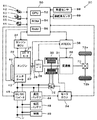
図1は、本発明の一実施例としてのハイブリッド自動車20の構成の概略を示す構成図である。実施例のハイブリッド自動車20は、図示するように、エンジン22と、エンジン22のクランクシャフト23に図示しないダンパを介して接続されたトルクコンバータ28と、このトルクコンバータ28にクラッチ29を介して接続されると共にデファレンシャルギヤ70を介して駆動輪72a,72bに接続された変速機36と、変速機36の入力側に動力を入出力する発電可能なモータ30と、エンジン22のクランクシャフト23にベルト42を介して接続されエンジン22の動力を用いて発電するオルタネータ40と、オルタネータ40やモータ30と電力のやりとりを行なう高圧バッテリ44と、オルタネータ40からの電力を電圧を低くして低圧バッテリ48や補機49側に供給するDC/DCコンバータ46と、車両全体をコントロールするハイブリッド用電子制御ユニット50と、を備える。
FIG. 1 is a configuration diagram showing an outline of the configuration of a
エンジン22は、ガソリンまたは軽油などの炭化水素系の燃料により動力を出力する内燃機関であり、エンジン22の運転状態を検出する各種センサから信号を入力するエンジン用電子制御ユニット(以下、エンジンECUという)24により燃料噴射制御や点火制御,吸入空気量調節制御などの運転制御を受けている。エンジン22のクランクシャフト23には、スタータモータ26が取り付けられており、必要に応じてクランキングされるようになっている。エンジンECU24は、ハイブリッド用電子制御ユニット50と通信しており、ハイブリッド用電子制御ユニット50からの制御信号によりエンジン22を運転制御すると共に必要に応じてエンジン22の運転状態に関するデータをハイブリッド用電子制御ユニット50に出力する。
The
モータ30は、発電機として駆動することができると共に電動機として駆動できる周知の同期発電電動機として構成されており、インバータ32を介してオルタネータ40や高圧バッテリ44が接続された高圧系と電力のやりとりを行なう。モータ30は、モータ用電子制御ユニット(以下、モータECUという)34により駆動制御されている。モータECU34には、モータ30を駆動制御するために必要な信号、例えばモータ30の回転子の回転位置を検出する回転位置検出センサ31からの信号や図示しない電流センサにより検出されるモータ30に印加される相電流などが入力されており、モータECU34からは、インバータ32へのスイッチング制御信号が出力されている。また、モータECU34は、高圧バッテリ44も管理しており、高圧バッテリ44からの電力ラインに接続された図示しない電流センサや電圧センサ,温度センサからのバッテリ電流Ibやバッテリ電圧Vb,バッテリ温度Tbなどを入力し、バッテリ電流Ibやバッテリ電圧Vbに基づいて高圧バッテリ44に蓄えられている電力量である残容量(SOC)や高圧バッテリ44の入出力制限Win,Woutを計算している。モータECU34は、ハイブリッド用電子制御ユニット50と通信しており、ハイブリッド用電子制御ユニット50からの制御信号によってモータ30を駆動制御すると共に必要に応じてモータ30の運転状態に関するデータや高圧バッテリ44の状態に関するデータをハイブリッド用電子制御ユニット50に出力する。
The
変速機36は、実施例では、例えばベルト駆動の無段変速機(CVT)として構成されており、トルクコンバータ28と共にオートマチックトランスミッション用電子制御ユニット(以下、ATECUという)38により制御されている。ATECU38は、トルクコンバータ28のロックアップを制御したり、クラッチ29のオンオフを制御したり、アクセル開度Accや車速Vに応じてその変速比γを変速したりする。このATECU38もハイブリッド用電子制御ユニット50と通信しており、ハイブリッド用電子制御ユニット50からの制御信号に基づいて変速機36の変速比γを変更する変速制御を実行すると共に必要に応じてトルクコンバータ28や変速機36の状態に関するデータをハイブリッド用電子制御ユニット50に出力する。
In the embodiment, the
ハイブリッド用電子制御ユニット50は、CPU52を中心とするマイクロプロセッサとして構成されており、CPU52の他に処理プログラムを記憶するROM54と、データを一時的に記憶するRAM56と、図示しない入出力ポートおよび通信ポートとを備える。ハイブリッド用電子制御ユニット50には、シフトレバー61の操作位置を検出するシフトポジションセンサ62からのシフトポジションSP,アクセルペダル63の踏み込み量を検出するアクセルペダルポジションセンサ64からのアクセル開度Acc,ブレーキペダル65の踏み込み量を検出するブレーキペダルポジションセンサ66からのブレーキポジションBP,車速センサ68からの車速V,操舵角センサ69からの操舵角θなどが入力ポートを介して入力されている。ハイブリッド用電子制御ユニット50からは、オルタネータ40への駆動信号やDC/DCコンバータ46へのスイッチング制御信号などが出力ポートを介して出力されている。また、ハイブリッド用電子制御ユニット50は、前述したように、エンジンECU24やモータECU34,ATECU38と通信ポートを介して接続されており、エンジンECU24やモータECU34,ATECU38と各種制御信号やデータのやりとりを行なっている。
The hybrid
こうして構成された実施例のハイブリッド自動車20は、クラッチ29をオン(接続)として主としてエンジン22からの動力を変速機36により変速して駆動輪72a,72bに出力することにより走行したり、クラッチ29をオフ(非接続)としてエンジン22の運転を停止した状態でモータ30からの動力を変速機36により変速して駆動輪72a,72bに出力することにより走行したりする。主としてエンジン22からの動力を用いて走行する場合には、更に、モータ30を力行駆動したり回生駆動したりすることによる高圧バッテリ44の充放電を伴って走行する場合も含まれる。また、ハイブリッド自動車20は、制動力を付与するときには、クラッチ29をオフ(非接続)としてモータ30を回生制御することにより、車両の運動エネルギを回収して燃費の向上を図っている。
The thus configured
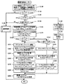
次に、実施例のハイブリッド自動車20の動作、特に踏み込んでいたアクセルペダル63を離してアクセルオフしたときの動作について説明する。図2は実施例のハイブリッド自動車20のハイブリッド用電子制御ユニット50により実行される駆動制御ルーチンの一例を示すフローチャートであり、図3は駆動制御ルーチンで用いられる目標車速V*を設定する目標車速設定ルーチンの一例を示すフローチャートである。この目標車速設定ルーチンもハイブリッド用電子制御ユニット50により実行される。駆動制御ルーチンも目標車速設定ルーチンもハイブリッド自動車20が始動されてから所定時間毎(例えば数msec毎)に繰り返し実行される。以下、まず駆動制御について説明し、その後に目標車速V*の設定について説明する。
Next, the operation of the
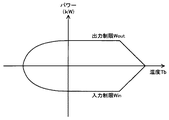
駆動制御ルーチンが実行されると、ハイブリッド用電子制御ユニット50のCPU52は、まず、アクセルペダルポジションセンサ64からのアクセル開度Accやブレーキペダルポジションセンサ66からのブレーキポジションBP,車速センサ68からの車速V,モータ30の回転数Nm,オルタネータ40の発電電力Pg,高圧バッテリ44の残容量(SOC),高圧バッテリ44の入出力制限Win,Woutなど制御に必要なデータを入力する処理を実行する(ステップS100)。ここで、モータ30の回転数Nmは、回転位置検出センサ31により検出されるモータ30の回転子の回転位置に基づいて計算されたものをモータECU34から通信により入力するものとした。また、オルタネータ40の発電電力Pgは、オルタネータ40の発電指令から計算したものを用いるものとした。さらに、高圧バッテリ44の残容量(SOC)や入出力制限Win,Woutは、高圧バッテリ44からの電力ラインに接続された図示しない電流センサや電圧センサ,温度センサからのバッテリ電流Ibやバッテリ電圧Vb,バッテリ温度Tbなどに基づいて計算したものをモータECU34から通信により入力するものとした。なお、高圧バッテリ44の入出力制限Win,Woutは、電池温度Tbに基づいて入出力制限Win,Woutの基本値を設定し、高圧バッテリ44の残容量(SOC)に基づいて出力制限用補正係数と入力制限用補正係数とを設定し、設定した入出力制限Win,Woutの基本値に補正係数を乗じて入出力制限Win,Woutを設定することができる。図4に電池温度Tbと入出力制限Win,Woutとの関係の一例を示し、図5に高圧バッテリ44の残容量(SOC)と入出力制限Win,Woutの補正係数との関係の一例を示す。
When the drive control routine is executed, first, the
こうしてデータを入力すると、入力したアクセル開度Accに基づいてアクセルオフの状態(値0)であるか否か(ステップS110)、ブレーキポジションBPに基づいてブレーキオフの状態(値0)であるか否か(ステップS120)、目標車速V*が設定されているか否か(ステップS130)、を判定する。アクセル開度Accに基づきアクセルオンの状態(値0でない状態)のときには、アクセル開度Accに基づいてエンジン22やモータ30から駆動輪72a,72bに動力を出力して走行する通常の駆動制御(図中、通常制御)を実行して(ステップS140)、本ルーチンを終了する。通常制御としては、例えば、アクセル開度Accに基づいてエンジン22のスロットル開度を調整すると共にモータ30のトルク指令Tm*を設定するなどの制御を行なうことができる。なお、こうした通常制御は、本発明の中核をなさないのでこれ以上の詳細な説明は省略する。アクセル開度Accに基づいてアクセルオフの状態と判定されるが、ブレーキポジションBPに基づいてブレーキオンの状態(値0でない状態)のときには、ブレーキポジションBPとモータ30の回転数Nmとに基づいてモータ30のトルク指令Tm*を設定すると共に(ステップS150)、エンジン22の目標トルクTe*に値0を設定して(ステップS155)、目標トルクTe*についてはエンジンECU24に、トルク指令Tm*についてはモータECU34に送信して(ステップS290)、本ルーチンを終了する。ブレーキポジションBPとモータ30の回転数Nmとに基づくトルク指令Tm*の設定は、実施例では、ブレーキポジションBPと回転数Nmとトルク指令Tm*との関係を予め定めてトルク設定用マップとしてROM54に記憶しておき、ブレーキポジションBPと回転数Nmとが与えられると記憶したマップから対応するトルク指令Tm*を導出して設定するものとした。図6にトルク設定用マップの一例を示す。図示するように、ブレーキポジションBPに対応するトルク指令Tm*の設定であるから、トルク指令Tm*には負の値、即ち発電用のトルク指令が設定される。値0の目標トルクTe*を受信したエンジンECU24は、エンジン22が運転されているときにはフューエルカットし、エンジン22を運転停止しているときにはその状態を保持する。トルク指令Tm*を受信したモータECU34は、トルク指令Tm*でモータ30が駆動されるようインバータ31のスイッチング素子のスイッチング制御を行なう。こうした制御により、ブレーキペダル65の踏み込みに応じた回生トルクがモータ30から出力され、得られる回生電力を用いて高圧バッテリ44を充電することができ、ハイブリッド自動車20の運動エネルギを電気エネルギとして回収することができる。アクセル開度AccおよびブレーキポジションBPに基づいてアクセルオフの状態とブレーキオフの状態が判定されたが、目標車速V*が設定されていないときには、目標車速V*に基づく制御を行なう必要がないため、通常制御を実行して(ステップS140)、本ルーチンを終了する。
When the data is input in this way, whether the accelerator is off (value 0) based on the input accelerator opening Acc (step S110) or whether the brake is off (value 0) based on the brake position BP. It is determined whether or not the target vehicle speed V * is set (step S130). When the accelerator is on (non-zero value) based on the accelerator opening Acc, the normal driving control for traveling by outputting power to the
アクセル開度AccおよびブレーキポジションBPに基づいてアクセルオフの状態とブレーキオフの状態が判定され、目標車速V*が設定されているときには、車速Vが目標車速V*となるよう以下に説明するステップS160〜S290の定速走行制御(巡航走行制御)を実行する。定速走行制御は、まず、モータ30の回転数Nmに基づいて定格値からモータ30から出力してもよいトルクの上下限である定格制限トルクTmax1,Tmin1を設定すると共に(ステップS160)、発電電力Pgと入出力制限Win,Woutとに基づいてモータ30から出力してもよいトルクの上下限である入出力制限トルクTmax2,Tmin2を次式(1)および式(2)により計算して設定する(ステップS170)。定格制限トルクTmax1,Tmin1は、モータ30の定格トルクと回転数Nmとの関係を定格制限トルク設定用マップとしてROM54に記憶しておき、回転数Nmが与えられると記憶したマップから対応する定格トルクを導出して設定するものとした。図7に定格制限トルク設定用マップの一例を示す。
Steps described below so that when the accelerator off state and the brake off state are determined based on the accelerator opening Acc and the brake position BP and the target vehicle speed V * is set, the vehicle speed V becomes the target vehicle speed V *. The constant speed traveling control (cruising traveling control) of S160 to S290 is executed. In the constant speed running control, first, rated limit torques Tmax1 and Tmin1 that are upper and lower limits of torque that may be output from the
Tmax2=(Wout+Pg)/Nm (1)
Tmin2=(Win+Pg)/Nm (2)
Tmax2 = (Wout + Pg) / Nm (1)
Tmin2 = (Win + Pg) / Nm (2)
こうして定格制限トルクTmax1,Tmin1や入出力制限トルクTmax2,Tmin2を設定すると、車速Vを閾値Vegと比較すると共に(ステップS180)、高圧バッテリ44の残容量(SOC)を閾値Srefと比較する(ステップS190)。ここで、閾値Vegは、エンジン22の運転の有無を判定する車速であり、車重やモータ30の性能,変速機36の性能などにより定めることができる。実施例では、若干の上り下りが生じてもモータ30からの動力によりほぼ定速走行を維持することができる程度の車速の上限値近傍の車速として閾値Vegを定めた。また、閾値Srefは、モータ走行の可否を判定するものであり、高圧バッテリ44の性能やモータ30の性能などによりさだめることができる。実施例では、高圧バッテリ44の過放電の可能性が小さい残容量(SOC)、例えば10%や15%などとして定めた。
When the rated limit torques Tmax1, Tmin1 and the input / output limit torques Tmax2, Tmin2 are set in this way, the vehicle speed V is compared with the threshold value Veg (step S180), and the remaining capacity (SOC) of the high-
車速Vが閾値Veg未満で高圧バッテリ44の残容量(SOC)が閾値Sref以上のときには、モータ走行による定速走行が可能と判断し、クラッチ29をオフ(非接続)とすると共にエンジン22の運転を停止し(ステップS200)、車速Vが目標車速V*になるようモータ30から出力すべきトルクをフィードバック制御における関係式としての次式(3)により仮モータトルクTmtmpとして計算すると共に(ステップS210)、計算した仮モータトルクTmtmpを定格制限トルクTmax1,Tmin1および入出力制限トルクTmax2,Tmin2で制限してモータ30のトルク指令Tm*を設定し(ステップS220)、設定したトルク指令Tm*をモータECU34に送信して(ステップS290)、本ルーチンを終了する。エンジン22の停止は、エンジンECU24に停止用の制御信号を送信することにより、エンジンECU24が燃料噴射制御や点火制御などを停止することにより行なわれる。このようにエンジン22を停止すると共にモータ30を駆動制御することにより、モータ30の定格値の範囲内で且つ高圧バッテリ44の入出力制限Win,Woutの範囲内でモータ走行による定速走行(巡航走行)を行なうことができる。なお、式(3)中、右辺第1項の「k1」は比例項のゲインであり、右辺第2項の「k2」は積分項のゲインである。また、ステップS290では目標トルクTe*も送信することになるが、この場合、エンジン22の運転は停止されているから、その送信は行なう必要はないが、図示の都合上、トルク指令Tm*の送信もステップS290により行なうものとした。
When the vehicle speed V is less than the threshold value Veg and the remaining capacity (SOC) of the
Tmtmp=k1・(V*-V)+k2∫(V*-V)dt (3) Tmtmp = k1 ・ (V * -V) + k2∫ (V * -V) dt (3)
車速Vが閾値Veg以上のときや高圧バッテリ44の残容量(SOC)が閾値Sref未満のときには、モータ走行による定速走行は不能と判断し、クラッチ29をオン(接続)とすると共にエンジン22を運転し(ステップS230)、エンジン22を効率よく運転することができる最適燃費ラインとモータ30の回転数Nmとに基づいてエンジン22から出力すべき仮エンジントルクTetmpを設定すると共に(ステップS240)、上述の式(3)の仮モータトルクTmtmpの計算と同様の計算により制御トルクT*を計算し(ステップS250)、計算した制御トルクT*から仮エンジントルクTetmpを減じて仮モータトルクTmtmpを設定する(ステップS260)。エンジン22の最適燃費ラインの一例と回転数Nmや仮エンジントルクTetmp,制御トルクT*,仮モータトルクTmtmpの関係の一例を図8に示す。定速走行中では、大きな動力の出力は行なわれないから、トルクコンバータ28はロックアップしており、エンジン22はモータ30の回転数Nmで回転する。したがって、エンジン22の最適燃費ラインを用いて仮エンジントルクTetmpを設定する際にモータ30の回転数Nmを用いることができる。図8に示すように、最適燃費ラインを用いて設定した仮エンジントルクTetmpは、車速Vを目標車速V*とするのに出力すべき制御トルクT*に一致しないから、その差分のトルクをモータ30から出力すれば、高圧バッテリ44の充放電を伴うが、エンジン22を最適燃費ライン上の運転ポイントで運転しながら制御トルクT*を出力することができる。実施例では、こうしたモータ30から出力するトルクとして仮モータトルクTmtmpを設定するである。
When the vehicle speed V is equal to or higher than the threshold value Veg or the remaining capacity (SOC) of the
仮モータトルクTmtmpを設定すると、設定した仮モータトルクTmtmpを定格制限トルクTmax1,Tmin1および入出力制限トルクTmax2,Tmin2で制限してモータ30のトルク指令Tm*を設定すると共に(ステップS270)、設定したトルク指令Tm*を制御トルクT*から減じてエンジン22の目標トルクTe*を設定し(ステップS280)、設定した目標トルクTe*についてはエンジンECU24に、設定したトルク指令Tm*についてはモータECU34に、それぞれ送信して(ステップS290)、本ルーチンを終了する。ここで、仮モータトルクTmtmpがモータ30の定格値の範囲内で且つ高圧バッテリ44の入出力制限Win,Woutの範囲内のときには、仮モータトルクTmtmpがそのままモータ30のトルク指令Tm*に設定されるから、エンジン22の目標トルクTe*にも仮エンジントルクTetmpがそのまま設定される。したがって、この場合、エンジン22を効率よく運転しながら車速Vを目標車速V*にするトルクを出力すること、即ち目標車速V*による定速走行(巡航走行)を行なうことができる。仮モータトルクTmtmpが定格制限トルクTmax1,Tmin1や入出力制限トルクTmax2,Tmin2で制限されてトルク指令Tm*が設定されたときには、仮エンジントルクTetmpとは若干異なるトルクがエンジン22の目標トルクTe*に設定されることになるが、仮モータトルクTetmpがそのまま目標トルクTe*に設定される場合に比して若干効率が低下する程度で車速Vを目標車速V*にするトルクを出力することができる。これにより、車両のエネルギ効率の向上を図ることができると共にモータ30の定格値の範囲内で且つ高圧バッテリ44の入出力制限Win,Woutの範囲内で車速Vを目標車速V*にするトルクを出力して車両を定速走行(巡航走行)することができる。
When the temporary motor torque Tmtmp is set, the set temporary motor torque Tmtmp is limited by the rated limit torques Tmax1, Tmin1 and the input / output limit torques Tmax2, Tmin2, and the torque command Tm * of the
次に、目標車速V*の設定について図3の目標車速設定ルーチンを用いて説明する。目標車速設定ルーチンが実行されると、ハイブリッド用電子制御ユニット50のCPU52は、まず、アクセルペダルポジションセンサ64からのアクセル開度Accやブレーキペダルポジションセンサ66からのブレーキポジションBP,車速センサ68からの車速V,操舵角履歴θrなど目標車速V*を設定する際に用いるデータを入力する処理を実行する(ステップS400)。ここで、操舵角履歴θrは、現時点から所定時間前(例えば、3秒前や5秒前など)までにブレーキペダル65の踏み込みと操舵が行なわれたときの操舵角θの大きさ(絶対値)の最大値であり、実施例では、図示しない操舵角履歴設定ルーチンにより検出されてRAM56の所定領域に記憶されたものを入力するものとした。
Next, the setting of the target vehicle speed V * will be described using the target vehicle speed setting routine of FIG. When the target vehicle speed setting routine is executed, first, the
こうしてデータを入力すると、アクセル開度Accに基づいてアクセルオフの状態(値0)であるか否かを判定し(ステップS410)、アクセルペダル63が踏み込まれてアクセルオンの状態にあるときには目標車速V*が設定されているときには目標車速V*の設定を解除して(ステップS420)、本ルーチンを終了する。即ち、目標車速V*はアクセルオンにより、その設定を解除するのである。
When data is thus input, it is determined whether or not the accelerator is off (value 0) based on the accelerator opening Acc (step S410). When the
ステップS410でアクセルオフの状態であると判定されたときには、前回このルーチンが実行されたときに入力したアクセル開度Accが値0であるか否か、即ち、アクセルオンの状態からアクセルオフの状態にされたかアクセルオフの状態が継続されているかを判定し(ステップS430)、アクセルオンの状態からアクセルオフの状態にされたときには、入力した車速Vを目標車速V*として設定して(ステップS440)、本ルーチンを終了する。即ち、運転者が踏み込んでいたアクセルペダル63を離してアクセルオフの状態としたときの車速Vを目標車速V*に設定するのである。これにより、これ以降は、図2の駆動制御ルーチンが実行されることにより、車速Vが目標車速V*に維持される定速走行(巡航走行)が行なわれる。
If it is determined in step S410 that the accelerator is in an off state, whether or not the accelerator opening Acc inputted when this routine was executed last time is 0, that is, from the accelerator on state to the accelerator off state. Whether the accelerator is off or the accelerator off state is maintained (step S430). When the accelerator on state is changed to the accelerator off state, the input vehicle speed V is set as the target vehicle speed V * (step S440). ), This routine is terminated. That is, the vehicle speed V when the driver depresses the
ステップS430でアクセルオフの状態が継続されていると判定されたときには、ブレーキポジションBPに基づいてブレーキオフの状態(値0)であるか否かを判定し(ステップS450)、ブレーキオンの状態のときには、ブレーキオフの状態からブレーキオンの状態にされたかブレーキオンの状態が継続されているかを判定する(ステップS460)。ブレーキオフの状態からブレーキオンの状態にされたと判定されたときには、それまで設定されている目標車速V*を前回目標車速Vpreに設定して記憶すると共に(ステップS470)、目標車速V*の設定を解除して(ステップS480)、本ルーチンを終了し、ブレーキオンの状態が継続されていると判定されたときには、前回目標車速Vpreは既に設定されていると共に目標車速V*の設定も解除されているから、そのまま、本ルーチンを終了する。即ち、運転者がブレーキペダル65を踏み込んだときに、そのときに設定されている目標車速V*を前回目標車速Vpreとして記憶し、目標車速V*の設定を解除するのである。
If it is determined in step S430 that the accelerator-off state continues, it is determined whether or not the brake is off (value 0) based on the brake position BP (step S450). Sometimes, it is determined whether the brake-off state is changed to the brake-on state or the brake-on state is continued (step S460). When it is determined that the brake is turned off from the brake-off state, the target vehicle speed V * that has been set up to that time is set and stored as the previous target vehicle speed Vpre (step S470), and the target vehicle speed V * is set. (Step S480), this routine is terminated, and when it is determined that the brake-on state is continued, the previous target vehicle speed Vpre is already set and the target vehicle speed V * is also released. Therefore, this routine is finished as it is. That is, when the driver depresses the
ステップS450でブレーキオフの状態であると判定されると、前回このルーチンが実行されたときに入力したブレーキポジションBPが値0であるか否か、即ち、ブレーキオンの状態からブレーキオフの状態にされたかブレーキオフの状態が継続されているかを判定し(ステップS490)、ブレーキオフの状態からブレーキオンの状態にされたときには、操舵角履歴θrを閾値θrefと比較する(ステップS500)。ここで、閾値θrefは、運転者が車両を右左折や右或いは左方向に旋回させるためにブレーキペダル65を踏み込んだか否かを判定するものであり、操舵装置の性能などにより定められる。操舵角履歴θrが閾値θref未満のときには、運転者によるブレーキペダル65の踏み込みは車両を右左折や右或いは左方向に旋回させるためではなく、単に車速を小さくするために行なわれたものと判断し、そのときの車速Vを目標車速V*に設定して(ステップS510)、本ルーチンを終了する。これにより、再び目標車速V*が設定されるから、それ以降は、図2に例示する駆動制御ルーチンを実行することにより、車速Vが目標車速V*に維持される定速走行(巡航走行)が行なわれる。一方、操舵角履歴θrが閾値θref以上のときには、運転者によるブレーキペダル65の踏み込みは車両を右左折や右或いは左方向に旋回させるためのものと判断し、ブレーキオフ後の車速を元の車速に戻すためにブレーキペダル65を踏み込んだときに記憶した前回目標車速Vpreを目標車速V*として設定して(ステップS520)、本ルーチンを終了する。これにより、車両を右左折や右或いは左方向に旋回させる前に設定されていた目標車速V*で車両を定速走行(巡航走行)させることができる。
If it is determined in step S450 that the brake is off, whether or not the brake position BP input when this routine was executed last time is 0, that is, from the brake-on state to the brake-off state. It is determined whether or not the brake-off state is continued (step S490), and when the brake-off state is changed to the brake-on state, the steering angle history θr is compared with a threshold θref (step S500). Here, the threshold value θref is used to determine whether or not the driver has depressed the
ステップS490でブレーキオフの状態が継続されていると判定されると、目標車速V*が設定されているか否かを判定し(ステップS530)、目標車速V*が設定されていないときには、そのまま本ルーチンを終了する。アクセルオフの状態とブレーキオフの状態とが継続されているが目標車速V*が設定されていないから、即ち、走行していない状態かアクセルペダル63を踏み込むことなくクリープトルクだけで走行している状態であるから、目標車速V*の設定や解除を行なうことなく、本ルーチンを終了するのである。
If it is determined in step S490 that the brake-off state continues, it is determined whether or not the target vehicle speed V * is set (step S530). If the target vehicle speed V * is not set, the present vehicle speed is unchanged. End the routine. The accelerator off state and the brake off state are continued, but the target vehicle speed V * is not set, that is, the vehicle is traveling only with creep torque without being depressed or without depressing the
ステップS530で目標車速V*が設定されていると判定されたときには、目標車速V*と車速Vとの偏差である車速偏差ΔVを計算すると共に(ステップS540)、計算した車速偏差ΔVの絶対値を閾値Vrefと比較し(ステップS550)、車速偏差ΔVの絶対値が閾値Vrefより大きいときには車速Vから目標車速V*方向に閾値Vrefだけ異なる値を新たな目標車速V*として設定して(ステップS560)、本ルーチンを終了する。ここで、閾値Vrefは、車速Vに応じて新たな目標車速V*を設定する必要があるかを判定するためのものであり、例えば3km/hや5km/h,7km/hなどのように定めることができる。モータ30は、実施例では、モータ走行時には比較的大きな加速度によって車両を加減速するには非力な性能のモータとして構成されているから、モータ走行による定速走行時に車両が比較的急な登坂路や降坂路を走行すると、図2の駆動制御ルーチンにより目標車速V*で走行するために必要なトルクとして仮モータトルクTmtmpにモータ30の力行限界や回生限界のトルクより大きな或いは小さなトルクが計算され(ステップS210)、この計算された仮モータトルクTmtmpが定格制限トルクTmax1,Tmin1によって制限されてトルク指令Tm*が設定されるため(ステップS220)、モータ30から車両の車速Vを目標車速V*にするのに必要なトルクを出力することができず、車速Vが目標車速V*から次第に離れていく。このとき、目標車速V*をそのまま維持しておくと、登坂路や降坂路の終了近傍で車速Vを目標車速V*にするために大きな駆動トルクや制動トルクがトルク指令Tm*に設定されてモータ30が駆動されることになるから、運転者の予期しない駆動トルクや制動トルクが作用することになり、運転者に違和感を与え、運転者の運転フィーリングを悪化させてしまう。実施例では、こうした運転フィーリングの悪化を抑制するために、車速Vが目標車速V*から閾値Vrefより離れたときには、車速Vから閾値Vrefだけ目標車速V*の方向にスライドさせた車速を新たな目標車速V*として設定するのである。これにより、登坂路や降坂路の終了近傍で運転者の予期しない駆動トルクや制動トルクが作用することによる運転フィーリングの悪化を抑制することができる。また、このように目標車速V*を変更することにより、エンジン22の運転停止を継続させることができ、エンジン22の頻繁な始動と運転停止を抑制することができる。
When it is determined in step S530 that the target vehicle speed V * is set, a vehicle speed deviation ΔV that is a deviation between the target vehicle speed V * and the vehicle speed V is calculated (step S540), and the absolute value of the calculated vehicle speed deviation ΔV is calculated. Is compared with the threshold value Vref (step S550), and when the absolute value of the vehicle speed deviation ΔV is larger than the threshold value Vref, a value different from the vehicle speed V by the threshold value Vref in the direction of the target vehicle speed V * is set as the new target vehicle speed V * (step S550). S560), this routine is finished. Here, the threshold value Vref is used to determine whether a new target vehicle speed V * needs to be set according to the vehicle speed V. For example, 3 km / h, 5 km / h, 7 km / h, etc. Can be determined. In the embodiment, the
ステップS550で車速偏差ΔVの絶対値が閾値Vref以下であると判定されると、車速Vが第1車速V1とこの第1車速V1より大きな第2車速V2との範囲内にあるか否かを判定し(ステップS570)、車速Vがこの範囲内にあるときにはこれで本ルーチンを終了し、車速Vが第1車速V1未満のときには、目標車速V*に調整車速Vrtを加えた値を新たな目標車速V*として設定して(ステップS580)、本ルーチンを終了し、車速Vが第2車速V2より大きいときには目標車速V*から調整車速Vrtを減じた値を新たな目標車速V*として設定して(ステップS590)、本ルーチンを終了する。ここで、第1車速V1は徐々に車速を増加することにより運転者による運転がブレーキペダル65の操作だけで行なうことができるために運転が容易なものとなる車速範囲の上限近傍の車速として設定されており、例えば15km/hや20km/h,25km/hなどのように定めることができる。また、第2車速V2は、徐々に車速を減少しないと運転者に空走感を与えてしまう虞がある車速範囲の下限近傍の車速として設定されており、例えば30km/hや40km/h,50km/hなどのように定めることができる。さらに、調整車速Vrtは、目標車速V*を徐々に変更するのに違和感を感じさせない程度の値として設定されており、目標車速設定ルーチンが実行される時間間隔などにより定められる。このように、車速Vが第1車速V1未満のときに目標車速V*を徐々に大きくすることにより、運転者による車両の運転をブレーキペダル65の操作だけで行なうことができるようにし、アクセルペダル63とブレーキペダル65の頻繁な踏み替えを抑制することができ、運転を容易なものとすることができる。また、車速Vが第2車速V2より大きいときに目標車速V*を徐々に小さくすることにより、運転者に空走感を与えるのを抑制することができる。
If it is determined in step S550 that the absolute value of the vehicle speed deviation ΔV is equal to or less than the threshold value Vref, it is determined whether or not the vehicle speed V is within the range of the first vehicle speed V1 and the second vehicle speed V2 that is greater than the first vehicle speed V1. This routine is terminated when the vehicle speed V is within this range, and when the vehicle speed V is less than the first vehicle speed V1, a value obtained by adding the adjusted vehicle speed Vrt to the target vehicle speed V * is newly determined. The target vehicle speed V * is set (step S580), and this routine is terminated. When the vehicle speed V is higher than the second vehicle speed V2, a value obtained by subtracting the adjusted vehicle speed Vrt from the target vehicle speed V * is set as the new target vehicle speed V *. (Step S590), and this routine is finished. Here, the first vehicle speed V1 is set as a vehicle speed in the vicinity of the upper limit of the vehicle speed range in which driving by the driver can be performed only by operating the
図9は、アクセルオフしたことにより目標車速V*が設定されて定速走行(巡航走行)している最中のアクセルやブレーキの状態,車速V,目標車速V*,エンジン22の状態,モータ30の出力,車両の加速度の時間変化の一例を示す説明図である。図示するように、時間T1にアクセルオフされてそのときの車速Vが目標車速V*に設定され、エンジン22の運転が停止されてモータ走行による定速走行(巡航走行)が開始される。ここで、車速Vが閾値Vegより大きいときや高圧バッテリ44の残容量(SOC)が閾値Sref未満のときにはエンジン22は運転が継続され、エンジン22の最適燃費ライン上での運転による定速走行(巡航走行)が開始されることになる。車両が降坂路を走行するとモータ30の出力は回生トルクの出力に変化し、回生限界に至った時間T2から車速Vは徐々に大きくなる。これに伴って車速Vと目標車速V*との偏差が閾値Vrefより大きくなると、目標車速V*が徐々に大きく設定される。時間T3に運転者がブレーキペダル65を踏み込むと、目標車速V*の設定が解除され、車速Vが減少する。時間T4に運転者がブレーキペダル65を離すとブレーキオフに伴ってそのときの車速Vが目標車速V*に設定され、再び定速走行(巡航走行)が実行される。なお、右左折などのために運転者がハンドルを大きく操作すれば、ブレーキオフ時に操舵角履歴θrの絶対値が閾値θrefより大きくなるから、その場合、ブレーキオン時に記憶された前回目標車速Vpreが目標車速V*に設定されて定速走行(巡航走行)が実行される。車両が登坂路を走行し始めると、モータ30の出力は大きくなり、その力行限界に至った時間T5を超えると車速Vは徐々に小さくなる。これに伴って車速Vと目標車速V*との偏差の絶対値が閾値Vrefより大きくなると、目標車速V*が徐々に小さく設定される。登坂路の終盤に近づいた時間T7では、目標車速V*と車速Vとの偏差を打ち消すために若干の加速が行なわれる。そして、運転者が加速するためにアクセルペダル63を踏み込んだ時間T8に目標車速V*の設定が解除され、エンジン22が始動される。
FIG. 9 shows the state of the accelerator and brake during the constant speed travel (cruising travel) with the target vehicle speed V * set by turning off the accelerator, the vehicle speed V, the target vehicle speed V *, the state of the
以上説明した実施例のハイブリッド自動車20によれば、アクセルオンの状態からアクセルオフとするだけで目標車速V*を設定して定速走行(巡航走行)を開始するから、定速走行(巡航走行)をより容易により迅速に実行することができる。しかも、目標車速V*が設定されているときに運転者がブレーキペダル65を踏み込み、その後にブレーキペダル65を離したときには、そのときの車速Vを目標車速V*に設定して定速走行(巡航走行)を再開するから、定速走行(巡航走行)をより容易により迅速に再開することができる。また、ブレーキペダル65を踏み込んだときにハンドル操作を行なうと、ブレーキペダル65を踏み込む直前に設定されていた目標車速V*を再び目標車速V*として設定するから、右左折した後に元の車速に容易に戻すことができる。これらの結果、運転状況に応じて定速走行(巡航走行)を行なうことができる。
According to the
また、実施例のハイブリッド自動車20によれば、車速Vが目標車速V*から閾値Vref以上離れたときには車速Vから目標車速V*方向に閾値Vrefだけ異なる値を新たな目標車速V*として設定するから、登坂路や降坂路の終了近傍で運転者の予期しない駆動トルクや制動トルクが作用することにより運転者に違和感を与えたり運転者の運転フィーリングを悪化させるなどの不都合を抑制することができる。これにより、エンジン22の運転停止を継続させることができ、エンジン22の頻繁な始動と運転停止を抑制することができる。さらに、車速Vが第1車速V1未満のときには徐々に目標車速V*が増加するよう目標車速V*を設定することにより、運転者による車両の運転をブレーキペダル65の操作だけで行なうことができるようにし、アクセルペダル63とブレーキペダル65の頻繁な踏み替えを抑制することができ、運転を容易なものとすることができる。或いは、車速Vが第2車速V2より大きいときには徐々に目標車速V*が減少するよう目標車速V*を設定することにより、運転者に空走感を与えるのを抑制することができる。これらの結果、運転状況に応じて定速走行(巡航走行)を行なうことができる。
Further, according to the
さらに、実施例のハイブリッド自動車20によれば、車速Vが閾値Veg以上のときや高圧バッテリ44の残容量(SOC)が閾値Sref未満のときには、モータ30の回転数Nmでエンジン22が効率よく運転できるように最適燃費ラインを用いてエンジン22を運転し、制御トルクT*とエンジン22から出力されるトルクとの差分のトルクが出力されるようモータ30を制御することにより、定速走行(巡航走行)におけるエネルギ効率を向上させることができる。
Furthermore, according to the
実施例のハイブリッド自動車20では、目標車速V*が設定されているときにブレーキオフの状態からブレーキオンの状態にされたときに目標車速V*を前回目標車速Vpreとして記憶して目標車速V*の設定を解除し、ブレーキオンの状態からブレーキオフの状態にされたときに操舵角履歴θrの絶対値が閾値θref以下のときにそのときの車速Vを目標車速V*に設定し、ブレーキオンの状態からブレーキオフの状態にされたときに操舵角履歴θrが閾値θrefより大きいときには、運転者によるブレーキペダル65の踏み込みは車両を右左折や右或いは左方向に旋回させるためのものと判断し、記憶しておいた前回目標車速Vpreを目標車速V*として設定するものとしたが、操舵角履歴θrに拘わらず、ブレーキオンの状態からブレーキオフの状態にされたときにはそのときの車速Vを目標車速V*に設定するものとしてもよい。また、目標車速V*が設定されているときにブレーキオフの状態からブレーキオンの状態にされたときには目標車速V*の設定を解除するだけで、その後にブレーキオンの状態からブレーキオフの状態にされても目標車速V*の設定は行なわないものとしても構わない。
In the
実施例のハイブリッド自動車20では、車速Vが目標車速V*から閾値Vref以上離れたときには車速Vから目標車速V*方向に閾値Vrefだけ異なる値を新たな目標車速V*として設定するものとしたが、車速Vが目標車速V*から閾値Vref以上離れたときにはそのときの車速Vを新たな目標車速V*として設定するものとしても構わない。また、車速Vが目標車速V*から閾値Vref以上離れたときには目標車速V*の設定を解除するものとしても差し支えない。さらに、車速Vが目標車速V*から閾値Vref以上離れても目標車速V*を変更しないものとしても差し支えない。
In the
実施例のハイブリッド自動車20では、車速Vが第1車速V1未満のときには徐々に目標車速V*が増加するようにしたが、車速Vが第1車速V1未満でも目標車速V*を増加しないものとしても構わない。また、車速Vが第2車速V2より大きいときには徐々に目標車速V*が減少するようにしたが、車速Vが第2車速V2より大きいときでも目標車速V*を減少しないものとしても構わない。さらに、車速Vが第1車速V1未満のときには目標車速V*に調整車速Vrt加えた値を新たな目標車速V*として設定し、車速Vが第2車速V2より大きいときには目標車速V*から調整車速Vrtを減じた値を新たな目標車速V*として設定するものとしたが、車速Vが第1車速V1未満のときに目標車速V*に加える調整車速Vrtと車速Vが第2車速V2より大きいときに目標車速V*から減じる調整車速Vrtは同一の値を用いる必要はなく、異なる値を用いるものとしてもよい。
In the
実施例のハイブリッド自動車20では、アクセル開度Accに基づいてアクセルオフの状態と判定されるがブレーキポジションBPに基づいてブレーキオンの状態(値0でない状態)のときには、エンジン22の目標トルクTe*に値0を設定し、エンジン22が運転されているときにはフューエルカットするものとしたが、エンジン22の目標トルクTe*に値0を設定する代わりにクラッチ29をオフとすると共にエンジン22の運転を停止するものとしてもよい。
In the
実施例のハイブリッド自動車20では、車速Vが閾値Veg以上のときや高圧バッテリ44の残容量(SOC)が閾値Sref未満のときには、基本的には、モータ30の回転数Nmでエンジン22が効率よく運転できるように最適燃費ラインを用いて目標トルクTe*を設定し、制御トルクT*と目標トルクTe*との差分としてモータ30のトルク指令Tm*を設定してエンジン22やモータ30を制御することにより制御トルクT*を出力するものとしたが、例えば、平坦路で一人乗車の際に目標車速V*で定速走行するのに必要なトルクをエンジン22の目標トルクTe*に設定すると共に制御トルクT*と目標トルクTe*との差分をモータ30のトルク指令Tm*に設定してエンジン22やモータ30を制御することにより制御トルクT*を出力するものなど、他の手法によりエンジン22とモータ30とから制御トルクT*が出力されるようエンジン22やモータ30を制御するものとしてもよい。
In the
実施例のハイブリッド自動車20では、クラッチ29によりエンジン22を車軸側から切り離し可能となるよう構成し、クラッチ29によりエンジン22を切り離した状態でモータ30からの動力だけで定速走行するモータ走行による定速走行と、クラッチ29によりエンジン22を接続した状態でエンジン22からの動力を用いて定速走行するエンジン駆動による定速走行とを切り替えて行なうものとしたが、クラッチ29を備えず、常にエンジン駆動による定速走行を行なうものとしても構わない。
In the
実施例のハイブリッド自動車20では、変速機36として無段変速機(CVT)を用いるものとしたが、無段変速機としてはベルト式のものに限定されるものではなく、如何なる方式のものとしてもよいし、無段変速機に限定されるものではなく、有段変速機を用いるものとしてもよい。
In the
実施例のハイブリッド自動車20では、モータ30を変速機36のエンジン22側に取り付けるものとしたが、図10の変形例のハイブリッド自動車20Bに示すように、モータ30を変速機36のエンジン22側とは反対側に取り付けるものとしてもよい。この場合、エンジン22の運転を伴う定速走行において最適燃費ライン上の目標トルクTe*の設定は、モータ30の回転数Nmに代えてエンジン22の回転数や回転数Nmに変速比γを乗じた回転数を用いて最適燃費ライン上の目標トルクTe*を設定すればよい。
In the
実施例のハイブリッド自動車20では、デファレンシャルギヤ70を介して駆動輪72a,72bにエンジン22からの動力もモータ30からの動力も出力するようモータ30を取り付けたが、図11に例示する変形例20Cに示すように、エンジン22からの動力が出力される駆動輪72a,72bとは異なる駆動輪74a,74bにデファレンシャルギヤ73を介してモータ30からの動力が出力されるようモータ30を取り付けるものとしても構わない。この場合、エンジン22の運転を伴う定速走行において最適燃費ライン上の目標トルクTe*の設定は、モータ30の回転数Nmに代えてエンジン22の回転数を用いて最適燃費ライン上の目標トルクTe*を設定すればよい。
In the
実施例では、エンジン22とモータ30とを搭載するハイブリッド自動車20として説明したが、アクセルオフ時に目標車速V*を設定して定速走行することができる構成であれば、如何なる構成の自動車にも適用することができる。例えば、モータとバッテリを搭載した電気自動車にも適用することができるし、燃料電池とバッテリとモータとを搭載した燃料電池車にも適用することができるし、エンジンだけを搭載した通常のエンジン自動車にも適用することができる。
In the embodiment, the
実施例では、本発明をハイブリッド自動車20の形態として説明したが、こうした自動車の制御方法の形態としてもよい。
In the embodiment, the present invention has been described as a form of the
以上、本発明を実施するための最良の形態について実施例を用いて説明したが、本発明はこうした実施例に何等限定されるものではなく、本発明の要旨を逸脱しない範囲内において、種々なる形態で実施し得ることは勿論である。 The best mode for carrying out the present invention has been described with reference to the embodiments. However, the present invention is not limited to these embodiments, and various modifications can be made without departing from the gist of the present invention. Of course, it can be implemented in the form.
本発明は、自動車製造産業などに利用可能である。 The present invention is applicable to the automobile manufacturing industry.
20,20B,20C ハイブリッド自動車、22 エンジン、23 クランクシャフト、24 エンジン用電子制御ユニット(エンジンECU)、26 スタータモータ、28 トルクコンバータ、29 クラッチ、30 モータ、31 回転位置検出センサ、32 インバータ、34 モータ用電子制御ユニット(モータECU)、36 変速機、38 オートマチックトランスミッション用電子制御ユニット(ATECU)、40 オルタネータ、42 ベルト、44 高圧バッテリ、46 DC/DCコンバータ、48 低圧バッテリ、49 補機、50 ハイブリッド用電子制御ユニット、52 CPU、54 ROM、56 RAM、61 シフトレバー、62 シフトポジションセンサ、63 アクセルペダル、64 アクセルペダルポジションセンサ、65 ブレーキペダル、66 ブレーキペダルポジションセンサ、68 車速センサ、69 操舵角センサ、70,73 デファレンシャルギヤ、72a,72b,74a,74b 駆動輪、。
20, 20B, 20C Hybrid vehicle, 22 engine, 23 crankshaft, 24 electronic control unit for engine (engine ECU), 26 starter motor, 28 torque converter, 29 clutch, 30 motor, 31 rotational position detection sensor, 32 inverter, 34 Electronic control unit for motor (motor ECU), 36 Transmission, 38 Electronic control unit for automatic transmission (ATECU), 40 Alternator, 42 Belt, 44 High voltage battery, 46 DC / DC converter, 48 Low voltage battery, 49 Auxiliary machine, 50 Electronic control unit for hybrid, 52 CPU, 54 ROM, 56 RAM, 61 shift lever, 62 shift position sensor, 63 accelerator pedal, 64 accelerator pedal position sensor, 65 brake Key pedal, 66 brake pedal position sensor, 68 vehicle speed sensor, 69 steering angle sensor, 70, 73 differential gear, 72a, 72b, 74a, 74b driving wheel,
Claims (18)
運転者のアクセル操作を検出するアクセル操作検出手段と、
車速を検出する車速検出手段と、
運転者のブレーキ操作を検出するブレーキ操作検出手段と、
操舵角を検出する操舵角検出手段と、
前記アクセル操作検出手段によりアクセルオンの状態からアクセルオフが検出されたときに前記車速検出手段により検出される車速を目標車速として設定し、前記目標車速が設定されている最中に前記ブレーキ操作検出手段によりブレーキオフの状態からブレーキオンが検出されたとき及び/又は前記アクセル操作検出手段によりアクセルオフの状態からアクセルオンが検出されたときに前記目標車速の設定を解除し、前記目標車速が設定されている最中にブレーキオンが検出されたことにより前記目標車速の設定が解除されている間に前記操舵角検出手段により直進状態から所定操舵角未満の操舵角が検出された場合には、その後に前記ブレーキ操作検出手段によりブレーキオフが検出されたときに前記車速検出手段により検出される車速を前記目標車速として設定すると共に、前記目標車速が設定されている最中にブレーキオンが検出されたことにより前記目標車速の設定が解除されている間に前記操舵角検出手段により直進状態から所定操舵角以上の操舵角が検出された場合には、その後に前記ブレーキ操作検出手段によりブレーキオフが検出されたときに前記解除した目標車速を新たな目標車速として設定する目標車速設定手段と、
前記目標車速が設定されていないときには前記アクセル操作検出手段により検出されるアクセル操作に基づいて前記動力出力装置を制御し、前記目標車速が設定されているときには該設定されている目標車速で走行するよう前記動力出力装置を制御する制御手段と、 を備える車両。A power output device that outputs power for traveling;
An accelerator operation detecting means for detecting the driver's accelerator operation;
Vehicle speed detection means for detecting the vehicle speed;
Brake operation detection means for detecting the driver's brake operation;
Steering angle detection means for detecting the steering angle;
The vehicle speed detected by the vehicle speed detecting means when the accelerator operation is detected from the accelerator-on state by the accelerator operation detecting means is set as a target vehicle speed, and the brake operation detection is performed while the target vehicle speed is being set. When the brake-on is detected from the brake-off state by the means and / or when the accelerator-on is detected from the accelerator-off state by the accelerator operation detection means, the setting of the target vehicle speed is canceled and the target vehicle speed is set. When a steering angle less than a predetermined steering angle is detected from the straight traveling state by the steering angle detection means while the setting of the target vehicle speed is canceled due to the detection of brake-on during Thereafter, the vehicle speed detected by the vehicle speed detecting means when the brake off is detected by the brake operation detecting means. And sets as the target vehicle speed, the predetermined steering from the straight state by the steering angle detecting means during the setting of the target vehicle speed by a brake on while said target vehicle speed is set is detected is released A target vehicle speed setting means for setting the released target vehicle speed as a new target vehicle speed when a brake-off is detected by the brake operation detection means after that, when a steering angle of an angle or more is detected;
When the target vehicle speed is not set, the power output device is controlled based on the accelerator operation detected by the accelerator operation detection means, and when the target vehicle speed is set, the vehicle travels at the set target vehicle speed. And a control means for controlling the power output device.
前記動力出力装置は、走行用の動力を出力する発電可能な電動機と、該電動機と電力のやりとりが可能な蓄電手段と、を備え、
前記制御手段は、前記目標車速が設定されているときに該設定されている目標車速で走行する際には前記電動機からの動力により走行するよう制御する手段である
車両。The vehicle according to any one of claims 1 to 4 ,
The power output device includes a motor capable of generating electric power that outputs driving power, and power storage means capable of exchanging electric power with the motor,
The said control means is a means which controls to drive | work with the motive power from the said motor, when drive | working with the set target vehicle speed when the said target vehicle speed is set.
前記動力出力装置は、走行用の動力を出力可能な内燃機関と、走行用の動力を出力する発電可能な電動機と、該電動機と電力のやりとりが可能な蓄電手段と、を備え、
前記制御手段は、前記目標車速が設定されているときに該設定されている目標車速で走行する際には前記内燃機関と前記電動機とからの動力により走行するよう制御する手段である
車両。The vehicle according to any one of claims 1 to 4 ,
The power output device comprises an internal combustion engine capable of outputting power for traveling, a motor capable of generating electricity for outputting power for traveling, and a storage means capable of exchanging power with the motor,
The said control means is a means which controls to drive | work with the motive power from the said internal combustion engine and the said motor, when drive | working with the set target vehicle speed when the said target vehicle speed is set.
前記動力出力装置は、前記内燃機関からの動力の車軸側への伝達と前記内燃機関の前記車軸側からの切り離しとが可能な伝達切離手段を備え、
前記制御手段は、前記目標車速が設定されているときに該設定されている目標車速で走行する際には前記伝達切離手段により前記内燃機関が前記車軸側から切り離されて前記電動機からの動力により走行するよう前記内燃機関と前記電動機と前記伝達切離手段とを制御する手段である
車両。The vehicle according to claim 6 , wherein
The power output device includes transmission separating means capable of transmitting power from the internal combustion engine to the axle side and disconnecting the internal combustion engine from the axle side,
When the target vehicle speed is set, the control means is configured such that when the vehicle travels at the set target vehicle speed, the internal combustion engine is separated from the axle side by the transmission disconnecting means, and the power from the electric motor is A vehicle for controlling the internal combustion engine, the electric motor, and the transmission disconnecting means so as to travel by the vehicle.
前記動力出力装置は、前記内燃機関からの動力の車軸側への伝達と前記内燃機関の前記車軸側からの切り離しとが可能な伝達切離手段を備え、
前記制御手段は、前記目標車速が設定されているときに該設定されている目標車速で走行する際には、所定の切離条件が成立していないときには前記伝達切離手段により前記内燃機関からの動力が前記車軸側に伝達される状態で前記内燃機関と前記電動機とからの動力により走行するよう前記内燃機関と前記電動機と前記伝達切離手段とを制御し、前記所定の切離条件が成立しているときには前記伝達切離手段により前記内燃機関が前記車軸側から切り離されて前記電動機からの動力により走行するよう前記内燃機関と前記電動機と前記伝達切離手段とを制御する手段である
車両。The vehicle according to claim 6 , wherein
The power output device includes transmission separating means capable of transmitting power from the internal combustion engine to the axle side and disconnecting the internal combustion engine from the axle side,
When the vehicle is traveling at the set target vehicle speed when the target vehicle speed is set, the control means is controlled by the transmission disconnect means from the internal combustion engine when a predetermined disconnect condition is not satisfied. The internal combustion engine, the electric motor and the transmission disconnecting means are controlled so as to travel by the power from the internal combustion engine and the electric motor in a state where the power of the engine is transmitted to the axle side, and the predetermined disconnection condition is When established, the internal combustion engine is separated from the axle side by the transmission disconnecting means and controls the internal combustion engine, the electric motor, and the transmission disconnecting means so that the internal combustion engine travels by power from the electric motor. vehicle.
(a)前記アクセル操作検出手段によりアクセルオンの状態からアクセルオフが検出されたときに前記車速検出手段により検出される車速を目標車速として設定し、前記目標車速が設定されている最中に前記ブレーキ操作検出手段によりブレーキオフの状態からブレーキオンが検出されたとき及び/又は前記アクセル操作検出手段によりアクセルオフの状態からアクセルオンが検出されたときに前記目標車速の設定を解除し、前記目標車速が設定されている最中にブレーキオンが検出されたことにより前記目標車速の設定が解除されている間に前記操舵角検出手段により直進状態から所定操舵角未満の操舵角が検出された場合には、その後に前記ブレーキ操作検出手段によりブレーキオフが検出されたときに前記車速検出手段により検出される車速を前記目標車速として設定すると共に、前記目標車速が設定されている最中にブレーキオンが検出されたことにより前記目標車速の設定が解除されている間に前記操舵角検出手段により直進状態から所定操舵角以上の操舵角が検出された場合には、その後に前記ブレーキ操作検出手段によりブレーキオフが検出されたときに前記解除した目標車速を新たな目標車速として設定し、
(b)前記目標車速が設定されていないときには前記アクセル操作検出手段により検出されるアクセル操作に基づいて前記動力出力装置を制御し、前記目標車速が設定されているときには該設定されている目標車速で走行するよう前記動力出力装置を制御する
車両の制御方法。A power output device that outputs driving power, an accelerator operation detecting unit that detects a driver's accelerator operation, a vehicle speed detecting unit that detects a vehicle speed, a brake operation detecting unit that detects a driver's brake operation, and steering A vehicle control method comprising: a steering angle detection means for detecting an angle,
(A) The vehicle speed detected by the vehicle speed detecting means when the accelerator operation is detected from the accelerator-on state by the accelerator operation detecting means is set as a target vehicle speed, and the target vehicle speed is set while the target vehicle speed is being set. When the brake operation is detected from the brake-off state by the brake operation detection means and / or when the accelerator operation is detected from the accelerator-off state by the accelerator operation detection means, the setting of the target vehicle speed is canceled, and the target When a steering angle less than a predetermined steering angle is detected from the straight traveling state by the steering angle detecting means while the setting of the target vehicle speed is canceled because the brake-on is detected while the vehicle speed is set Is detected by the vehicle speed detecting means when the brake off is detected by the brake operation detecting means. Sets the vehicle speed as the target vehicle speed, from the straight state by the steering angle detecting means during the setting of the target vehicle speed by a brake on while said target vehicle speed is set is detected is released If the predetermined steering angle or the steering angle is detected, it sets a target vehicle speed and the release when the brake off is detected by subsequent to the brake operation detecting means as a new target vehicle speed,
(B) When the target vehicle speed is not set, the power output device is controlled based on the accelerator operation detected by the accelerator operation detecting means, and when the target vehicle speed is set, the set target vehicle speed A method for controlling a vehicle, wherein the power output device is controlled to travel on a vehicle.
Priority Applications (6)
| Application Number | Priority Date | Filing Date | Title |
|---|---|---|---|
| JP2005102119A JP4655723B2 (en) | 2005-03-31 | 2005-03-31 | Vehicle and control method thereof |
| PCT/JP2006/306773 WO2006106894A1 (en) | 2005-03-31 | 2006-03-24 | Vehicle and control method of vehicle |
| CN2006800042510A CN101115638B (en) | 2005-03-31 | 2006-03-24 | Vehicle and control method of vehicle |
| DE602006003318T DE602006003318D1 (en) | 2005-03-31 | 2006-03-24 | VEHICLE AND CONTROL PROCEDURE FOR THE VEHICLE |
| EP06730721A EP1863668B1 (en) | 2005-03-31 | 2006-03-24 | Vehicle and control method of vehicle |
| US11/632,126 US7715971B2 (en) | 2005-03-31 | 2006-03-24 | Vehicle and control method of vehicle |
Applications Claiming Priority (1)
| Application Number | Priority Date | Filing Date | Title |
|---|---|---|---|
| JP2005102119A JP4655723B2 (en) | 2005-03-31 | 2005-03-31 | Vehicle and control method thereof |
Publications (2)
| Publication Number | Publication Date |
|---|---|
| JP2006281899A JP2006281899A (en) | 2006-10-19 |
| JP4655723B2 true JP4655723B2 (en) | 2011-03-23 |
Family
ID=36499141
Family Applications (1)
| Application Number | Title | Priority Date | Filing Date |
|---|---|---|---|
| JP2005102119A Expired - Fee Related JP4655723B2 (en) | 2005-03-31 | 2005-03-31 | Vehicle and control method thereof |
Country Status (6)
| Country | Link |
|---|---|
| US (1) | US7715971B2 (en) |
| EP (1) | EP1863668B1 (en) |
| JP (1) | JP4655723B2 (en) |
| CN (1) | CN101115638B (en) |
| DE (1) | DE602006003318D1 (en) |
| WO (1) | WO2006106894A1 (en) |
Families Citing this family (69)
| Publication number | Priority date | Publication date | Assignee | Title |
|---|---|---|---|---|
| JP4539640B2 (en) * | 2006-11-08 | 2010-09-08 | トヨタ自動車株式会社 | Secondary battery input / output control device and vehicle |
| CN101209681B (en) * | 2006-12-26 | 2010-09-29 | 比亚迪股份有限公司 | Electric motor outputting torque moment control system and control method in electric automobile descending condition |
| JP4321619B2 (en) * | 2007-03-30 | 2009-08-26 | トヨタ自動車株式会社 | Vehicle and control method thereof |
| DE102007025502A1 (en) * | 2007-06-01 | 2008-12-04 | Zf Friedrichshafen Ag | Operating and driving control device for a motor vehicle and method thereto |
| JP2009006828A (en) * | 2007-06-27 | 2009-01-15 | Denso Corp | Vehicle speed control device and vehicle speed program |
| JP4623062B2 (en) * | 2007-07-27 | 2011-02-02 | トヨタ自動車株式会社 | Vehicle driving force control device |
| US8138703B2 (en) * | 2007-11-04 | 2012-03-20 | GM Global Technology Operations LLC | Method and apparatus for constraining output torque in a hybrid powertrain system |
| JP5217430B2 (en) * | 2007-12-28 | 2013-06-19 | トヨタ自動車株式会社 | Alternator control device and alternator control method |
| JP4596016B2 (en) * | 2008-02-12 | 2010-12-08 | トヨタ自動車株式会社 | Vehicle travel control device |
| JP5018544B2 (en) * | 2008-02-22 | 2012-09-05 | トヨタ自動車株式会社 | Vehicle travel control device |
| JP5051458B2 (en) * | 2008-03-06 | 2012-10-17 | トヨタ自動車株式会社 | Vehicle speed control device |
| JP4513882B2 (en) * | 2008-03-21 | 2010-07-28 | トヨタ自動車株式会社 | Hybrid vehicle and control method thereof |
| US8143822B2 (en) * | 2008-12-19 | 2012-03-27 | Tai-Her Yang | Bidirectional unequal speed electric motor driven bidirectional output system |
| US8143823B2 (en) * | 2008-12-19 | 2012-03-27 | Tai-Her Yang | Bidirectional different speed ratio electric motor driving device with bidirectional input |
| CN201403072Y (en) * | 2008-12-19 | 2010-02-10 | 杨泰和 | Bidirectional input and constant-direction output electric motor driving system |
| US20100156210A1 (en) * | 2008-12-19 | 2010-06-24 | Tai-Her Yang | Bidirectional unequal speed electric motor driven constant directional output system |
| JP5152865B2 (en) * | 2008-12-22 | 2013-02-27 | Udトラックス株式会社 | Fuel efficient driving evaluation system |
| EP2404803A4 (en) * | 2009-03-06 | 2016-08-10 | Toyota Motor Co Ltd | Vehicle travel control device |
| US8433494B2 (en) * | 2009-07-14 | 2013-04-30 | GM Global Technology Operations LLC | Operating device for a cruise control system in a vehicle with regenerative braking capability |
| KR101103877B1 (en) * | 2009-07-30 | 2012-01-12 | 현대자동차주식회사 | Method for controlling variable voltage for hybrid vehicle |
| US9428041B2 (en) * | 2009-12-16 | 2016-08-30 | Honda Motor Co., Ltd. | Hybrid vehicle and control method thereof |
| RU2538906C2 (en) | 2009-12-22 | 2015-01-10 | Хонда Мотор Ко., Лтд. | Hybrid transport facility control device |
| US8793067B2 (en) * | 2009-12-28 | 2014-07-29 | Honda Motor Co., Ltd. | Route searching device |
| US9046379B2 (en) * | 2009-12-28 | 2015-06-02 | Honda Motor Co., Ltd. | Devices and methods for determining fuel consumption and searching vehicle routes |
| KR101628385B1 (en) * | 2010-03-31 | 2016-06-08 | 현대자동차주식회사 | Control method for permanent magnet synchronous motor |
| EP2557302B1 (en) * | 2010-04-07 | 2016-09-07 | Toyota Jidosha Kabushiki Kaisha | Vehicle control device |
| DE102010039041A1 (en) * | 2010-08-09 | 2012-02-09 | Robert Bosch Gmbh | Method for operating a vehicle electrical system, control and computer program product |
| JP5037669B2 (en) | 2010-10-21 | 2012-10-03 | 日野自動車株式会社 | Output restriction control device, hybrid vehicle, output restriction control method, and program |
| WO2012053596A1 (en) * | 2010-10-22 | 2012-04-26 | 日野自動車株式会社 | Vehicle, control method, and program |
| US9132747B2 (en) | 2010-11-26 | 2015-09-15 | Toyota Jidosha Kabushiki Kaisha | Control device of vehicle drive device |
| US8738250B2 (en) * | 2010-11-30 | 2014-05-27 | Caterpillar Inc. | Power source speed control in a machine with a CVT |
| US9043060B2 (en) | 2010-12-31 | 2015-05-26 | Cummins Inc. | Methods, systems, and apparatuses for driveline load management |
| US9061684B2 (en) * | 2011-01-26 | 2015-06-23 | Toyota Jidosha Kabushiki Kaisha | Control device of hybrid vehicle |
| DE112011105550B4 (en) * | 2011-08-24 | 2018-01-11 | Toyota Jidosha Kabushiki Kaisha | A vehicle driving control device |
| TW201311483A (en) * | 2011-09-14 | 2013-03-16 | Hua Chuang Automobile Information Technical Ct Co Ltd | Downhill constant speed power recharge system |
| CN103072493A (en) * | 2011-10-26 | 2013-05-01 | 华创车电技术中心股份有限公司 | Downhill constant-speed electric power back-charging system |
| CN103917424B (en) * | 2011-11-14 | 2016-08-17 | 丰田自动车株式会社 | The control device of vehicle driving apparatus |
| KR101339247B1 (en) * | 2011-11-30 | 2014-01-06 | 기아자동차 주식회사 | Battery charging method for a hybrid vehicle and the hybrid vehicle using the same |
| DE102011120500B4 (en) * | 2011-12-07 | 2014-08-21 | Audi Ag | Method for operating a motor vehicle and motor vehicle |
| DE102012002761A1 (en) * | 2012-02-11 | 2013-08-14 | Volkswagen Aktiengesellschaft | Method and driver assistance system for automatically controlling the speed of a vehicle |
| US8989978B2 (en) | 2012-03-06 | 2015-03-24 | Ford Global Technologies, Llc | Method for operating a vehicle powertrain |
| DE112012001156T5 (en) * | 2012-03-30 | 2014-01-30 | Honda Motor Co., Ltd. | Control device for an internal combustion engine and control method for an internal combustion engine |
| JP5218928B2 (en) * | 2012-03-30 | 2013-06-26 | トヨタ自動車株式会社 | Vehicle speed control device |
| JP5927717B2 (en) * | 2012-03-30 | 2016-06-01 | 本田技研工業株式会社 | Travel control device |
| CA2866818A1 (en) * | 2012-04-11 | 2013-10-17 | Honda Motor Co., Ltd. | Electric power generation control system for hybrid automobile |
| US8740744B2 (en) * | 2012-05-07 | 2014-06-03 | Ford Global Technologies, Llc | Adjusting motor torque to compensate for uphill and downhill demands during cruise control in hybrid vehicle |
| US9914454B2 (en) * | 2012-12-07 | 2018-03-13 | Kelsey-Hayes Company | Vehicle speed control system |
| US8897943B2 (en) * | 2013-03-15 | 2014-11-25 | Deere & Company | Battery electric hybrid drive for a combine harvester |
| CN104167972B (en) * | 2013-05-20 | 2017-07-14 | 安川电机(中国)有限公司 | Controller for motor and motor control method |
| JP6167665B2 (en) * | 2013-05-22 | 2017-07-26 | 三菱自動車工業株式会社 | Driving assistance device |
| JP5811148B2 (en) * | 2013-07-11 | 2015-11-11 | トヨタ自動車株式会社 | Vehicle with regenerative generator |
| GB2520556B (en) * | 2013-11-26 | 2016-05-25 | Ford Global Tech Llc | A method of controlling a mild hybrid electric vehicle |
| US20150251647A1 (en) * | 2014-03-06 | 2015-09-10 | Ford Global Technologies, Llc | System and method for controlling a powertrain in a vehicle |
| US10569638B2 (en) * | 2014-06-25 | 2020-02-25 | Heinz Welschoff | All electric vehicle without plug-in requirement |
| JP5866520B2 (en) * | 2014-06-30 | 2016-02-17 | パナソニックIpマネジメント株式会社 | Vehicle drive system |
| KR101618453B1 (en) * | 2014-10-29 | 2016-05-04 | 쌍용자동차 주식회사 | one-pedal driving control method of electric car |
| EP3023290B1 (en) * | 2014-11-21 | 2018-04-18 | Visedo Oy | An electromechanical power transmission chain for a working machine |
| JP5940637B2 (en) * | 2014-12-16 | 2016-06-29 | 太陽誘電株式会社 | Motor drive control device and electric assist vehicle |
| WO2016110730A1 (en) * | 2015-01-05 | 2016-07-14 | 日産自動車株式会社 | Target vehicle speed generation device and drive control device |
| JP6406226B2 (en) * | 2015-11-27 | 2018-10-17 | 株式会社デンソー | Vehicle control device |
| CN105799508B (en) * | 2016-05-03 | 2020-09-04 | 王卫平 | Automobile speed control device with driver only needing to operate automobile brake pedal |
| DE102016222448A1 (en) * | 2016-11-16 | 2018-05-17 | Bayerische Motoren Werke Aktiengesellschaft | Operating method for a hybrid vehicle |
| US11584372B2 (en) * | 2016-12-28 | 2023-02-21 | Baidu Usa Llc | Method to dynamically adjusting speed control rates of autonomous vehicles |
| JP7251913B2 (en) * | 2017-06-28 | 2023-04-04 | トヨタ自動車株式会社 | Machine design method |
| CN109835335B (en) * | 2017-11-28 | 2021-11-09 | 蔚来(安徽)控股有限公司 | Electric vehicle cruise control method and system, vehicle, controller and storage medium |
| KR102427806B1 (en) * | 2017-12-06 | 2022-08-02 | 현대자동차주식회사 | Cvt control method for vehicle on winding road |
| CN110370940B (en) * | 2019-06-19 | 2022-07-22 | 四川野马汽车股份有限公司 | Steep slope slow-falling constant-speed cruise system and method |
| CN112498330A (en) * | 2019-08-26 | 2021-03-16 | 上海汽车集团股份有限公司 | Method and device for calculating gear-shifting speed-regulating target of parallel motor of hybrid electric vehicle |
| KR20210152209A (en) * | 2020-06-08 | 2021-12-15 | 현대자동차주식회사 | Control device and method for hybrid electric vehicle |
Citations (15)
| Publication number | Priority date | Publication date | Assignee | Title |
|---|---|---|---|---|
| JPH01306334A (en) * | 1988-06-03 | 1989-12-11 | Fujitsu Ten Ltd | Device for controlling constant speed running of automobile |
| JPH03159825A (en) * | 1989-11-17 | 1991-07-09 | Fujitsu Ten Ltd | Constant speed travel control device |
| JPH04176735A (en) * | 1990-11-08 | 1992-06-24 | Mazda Motor Corp | Constant velocity traveling device for vehicle |
| JPH05305822A (en) * | 1992-04-30 | 1993-11-19 | Aqueous Res:Kk | Hybrid powered vehicle |
| JPH07149168A (en) * | 1993-11-29 | 1995-06-13 | Aisin Seiki Co Ltd | Control device for driving power of vehicle |
| JPH09294308A (en) * | 1996-04-25 | 1997-11-11 | Nissan Motor Co Ltd | Controller of hybrid vehicle |
| JPH1178596A (en) * | 1997-09-02 | 1999-03-23 | Denso Corp | Constant-speed travel device for vehicle |
| JP2000004502A (en) * | 1998-06-11 | 2000-01-07 | Toyota Motor Corp | Method and device for detecting charging state of battery |
| JP2000008902A (en) * | 1998-06-17 | 2000-01-11 | Nissan Motor Co Ltd | Constant speed traveling control system for vehicle |
| JP2000247162A (en) * | 1999-02-26 | 2000-09-12 | Mitsubishi Motors Corp | Operating state evaluating device for vehicle |
| JP2000255279A (en) * | 1999-03-11 | 2000-09-19 | Nissan Motor Co Ltd | Control device for hybrid vehicle |
| JP2001157305A (en) * | 1999-11-25 | 2001-06-08 | Honda Motor Co Ltd | Autocruise control device of hybrid vehicle |
| JP2001173481A (en) * | 1999-12-17 | 2001-06-26 | Mitsubishi Motors Corp | Control device for vehicular generator |
| JP2001191814A (en) * | 2000-01-07 | 2001-07-17 | Toyota Motor Corp | Control device for vehicle |
| JP2001336466A (en) * | 2000-05-29 | 2001-12-07 | Mitsubishi Motors Corp | Hybrid car |
Family Cites Families (15)
| Publication number | Priority date | Publication date | Assignee | Title |
|---|---|---|---|---|
| KR930004579B1 (en) * | 1988-11-09 | 1993-06-01 | 미쯔비시 덴끼 가부시기가이샤 | Slow speed cruising control apparatus |
| JPH05193394A (en) * | 1991-07-22 | 1993-08-03 | Nippondenso Co Ltd | Constant speed traveling device for vehicle |
| JPH09242579A (en) | 1996-03-06 | 1997-09-16 | Toyota Motor Corp | Prime mover control device |
| GB2329725A (en) * | 1997-09-30 | 1999-03-31 | Ibm | Vehicle cruise control and engine idle control |
| US6324463B1 (en) | 1998-05-12 | 2001-11-27 | C. Kumar N. Patel | Cruise control indicator |
| JP2000006682A (en) | 1998-06-24 | 2000-01-11 | Aisin Seiki Co Ltd | Constant-speed travel device |
| JP4531876B2 (en) | 1998-07-23 | 2010-08-25 | 株式会社エクォス・リサーチ | Vehicle shift control device |
| KR100320527B1 (en) * | 1999-12-30 | 2002-01-15 | 이계안 | Shift controlling method for automatic transmission of vehicle |
| DE10145915A1 (en) | 2001-09-18 | 2003-04-03 | Volkswagen Ag | Motor vehicle speed regulation, involves converting speed plus or minus delta value produced by gas/brake pedal position for at least certain time into automatically regulated speed |
| FR2838386B1 (en) | 2002-04-11 | 2004-06-18 | Renault Sa | METHOD AND DEVICE FOR AUTOMATIC ACTIVATION OF A SPEED REGULATOR FOR VEHICLE |
| JP3729165B2 (en) * | 2002-09-03 | 2005-12-21 | トヨタ自動車株式会社 | Vehicle control apparatus and control method thereof |
| US7096109B2 (en) * | 2002-11-12 | 2006-08-22 | Hitachi, Ltd. | Adaptive cruise control system |
| JP3997955B2 (en) | 2003-06-23 | 2007-10-24 | トヨタ自動車株式会社 | Hybrid vehicle and control method thereof |
| DE10347844B4 (en) * | 2003-10-10 | 2006-04-13 | Daimlerchrysler Ag | Method and device for activating / deactivating a longitudinal dynamics system |
| JP4254586B2 (en) * | 2004-03-15 | 2009-04-15 | 日産自動車株式会社 | Deceleration control device |
-
2005
- 2005-03-31 JP JP2005102119A patent/JP4655723B2/en not_active Expired - Fee Related
-
2006
- 2006-03-24 DE DE602006003318T patent/DE602006003318D1/en active Active
- 2006-03-24 EP EP06730721A patent/EP1863668B1/en not_active Expired - Fee Related
- 2006-03-24 WO PCT/JP2006/306773 patent/WO2006106894A1/en active Application Filing
- 2006-03-24 US US11/632,126 patent/US7715971B2/en active Active
- 2006-03-24 CN CN2006800042510A patent/CN101115638B/en not_active Expired - Fee Related
Patent Citations (15)
| Publication number | Priority date | Publication date | Assignee | Title |
|---|---|---|---|---|
| JPH01306334A (en) * | 1988-06-03 | 1989-12-11 | Fujitsu Ten Ltd | Device for controlling constant speed running of automobile |
| JPH03159825A (en) * | 1989-11-17 | 1991-07-09 | Fujitsu Ten Ltd | Constant speed travel control device |
| JPH04176735A (en) * | 1990-11-08 | 1992-06-24 | Mazda Motor Corp | Constant velocity traveling device for vehicle |
| JPH05305822A (en) * | 1992-04-30 | 1993-11-19 | Aqueous Res:Kk | Hybrid powered vehicle |
| JPH07149168A (en) * | 1993-11-29 | 1995-06-13 | Aisin Seiki Co Ltd | Control device for driving power of vehicle |
| JPH09294308A (en) * | 1996-04-25 | 1997-11-11 | Nissan Motor Co Ltd | Controller of hybrid vehicle |
| JPH1178596A (en) * | 1997-09-02 | 1999-03-23 | Denso Corp | Constant-speed travel device for vehicle |
| JP2000004502A (en) * | 1998-06-11 | 2000-01-07 | Toyota Motor Corp | Method and device for detecting charging state of battery |
| JP2000008902A (en) * | 1998-06-17 | 2000-01-11 | Nissan Motor Co Ltd | Constant speed traveling control system for vehicle |
| JP2000247162A (en) * | 1999-02-26 | 2000-09-12 | Mitsubishi Motors Corp | Operating state evaluating device for vehicle |
| JP2000255279A (en) * | 1999-03-11 | 2000-09-19 | Nissan Motor Co Ltd | Control device for hybrid vehicle |
| JP2001157305A (en) * | 1999-11-25 | 2001-06-08 | Honda Motor Co Ltd | Autocruise control device of hybrid vehicle |
| JP2001173481A (en) * | 1999-12-17 | 2001-06-26 | Mitsubishi Motors Corp | Control device for vehicular generator |
| JP2001191814A (en) * | 2000-01-07 | 2001-07-17 | Toyota Motor Corp | Control device for vehicle |
| JP2001336466A (en) * | 2000-05-29 | 2001-12-07 | Mitsubishi Motors Corp | Hybrid car |
Also Published As
| Publication number | Publication date |
|---|---|
| CN101115638B (en) | 2010-05-19 |
| WO2006106894A1 (en) | 2006-10-12 |
| US7715971B2 (en) | 2010-05-11 |
| CN101115638A (en) | 2008-01-30 |
| JP2006281899A (en) | 2006-10-19 |
| EP1863668B1 (en) | 2008-10-22 |
| EP1863668A1 (en) | 2007-12-12 |
| DE602006003318D1 (en) | 2008-12-04 |
| US20070255477A1 (en) | 2007-11-01 |
Similar Documents
| Publication | Publication Date | Title |
|---|---|---|
| JP4655723B2 (en) | Vehicle and control method thereof | |
| JP5521340B2 (en) | Control device for hybrid vehicle | |
| JP5854315B2 (en) | Control device for hybrid vehicle | |
| US9186975B2 (en) | Control apparatus for hybrid vehicle | |
| JP2007055493A (en) | Vehicle and control method therefor | |
| JP5338351B2 (en) | Control device for hybrid vehicle | |
| JP4637770B2 (en) | Control device for hybrid electric vehicle | |
| JP6008425B2 (en) | Auto cruise control device for hybrid vehicle | |
| KR101040349B1 (en) | System and method for control hybrid electric vehicle | |
| WO2013027511A1 (en) | Hybrid vehicle control apparatus | |
| JP2007331599A (en) | Transmission status switching controller for hybrid vehicle | |
| JP2012091563A (en) | Hybrid vehicle control device | |
| JP2011088595A (en) | Controller for hybrid electric automobile | |
| JP2001103613A (en) | Controller of hybrid vehicle | |
| US6641501B2 (en) | Control apparatus for hybrid vehicle | |
| JP2004242450A (en) | Controller for hybrid vehicle | |
| WO2018189896A1 (en) | Electric vehicle control device and electric vehicle control method | |
| JP6554030B2 (en) | Control device for hybrid vehicle | |
| JP3572868B2 (en) | Vehicle control device | |
| JP3721830B2 (en) | Control device for hybrid vehicle | |
| JP7207919B2 (en) | Control device for engine-electric hybrid vehicle | |
| JP2012218689A (en) | Vehicle controller | |
| JP2011061946A (en) | Wheel slip controller for electric vehicle | |
| WO2018078803A1 (en) | Hybrid vehicle control method and control device | |
| JP2020019457A (en) | Hybrid vehicle |
Legal Events
| Date | Code | Title | Description |
|---|---|---|---|
| A621 | Written request for application examination |
Free format text: JAPANESE INTERMEDIATE CODE: A621 Effective date: 20071213 |
|
| A131 | Notification of reasons for refusal |
Free format text: JAPANESE INTERMEDIATE CODE: A131 Effective date: 20091117 |
|
| A521 | Request for written amendment filed |
Free format text: JAPANESE INTERMEDIATE CODE: A523 Effective date: 20100113 |
|
| A02 | Decision of refusal |
Free format text: JAPANESE INTERMEDIATE CODE: A02 Effective date: 20100601 |
|
| A521 | Request for written amendment filed |
Free format text: JAPANESE INTERMEDIATE CODE: A523 Effective date: 20100820 |
|
| A911 | Transfer to examiner for re-examination before appeal (zenchi) |
Free format text: JAPANESE INTERMEDIATE CODE: A911 Effective date: 20100921 |
|
| TRDD | Decision of grant or rejection written | ||
| A01 | Written decision to grant a patent or to grant a registration (utility model) |
Free format text: JAPANESE INTERMEDIATE CODE: A01 Effective date: 20101130 |
|
| A01 | Written decision to grant a patent or to grant a registration (utility model) |
Free format text: JAPANESE INTERMEDIATE CODE: A01 |
|
| A61 | First payment of annual fees (during grant procedure) |
Free format text: JAPANESE INTERMEDIATE CODE: A61 Effective date: 20101213 |
|
| FPAY | Renewal fee payment (event date is renewal date of database) |
Free format text: PAYMENT UNTIL: 20140107 Year of fee payment: 3 |
|
| R151 | Written notification of patent or utility model registration |
Ref document number: 4655723 Country of ref document: JP Free format text: JAPANESE INTERMEDIATE CODE: R151 |
|
| FPAY | Renewal fee payment (event date is renewal date of database) |
Free format text: PAYMENT UNTIL: 20140107 Year of fee payment: 3 |
|
| LAPS | Cancellation because of no payment of annual fees |