JP4596016B2 - Vehicle travel control device - Google Patents
Vehicle travel control device Download PDFInfo
- Publication number
- JP4596016B2 JP4596016B2 JP2008030150A JP2008030150A JP4596016B2 JP 4596016 B2 JP4596016 B2 JP 4596016B2 JP 2008030150 A JP2008030150 A JP 2008030150A JP 2008030150 A JP2008030150 A JP 2008030150A JP 4596016 B2 JP4596016 B2 JP 4596016B2
- Authority
- JP
- Japan
- Prior art keywords
- acceleration
- deceleration
- travel
- pattern
- vehicle speed
- Prior art date
- Legal status (The legal status is an assumption and is not a legal conclusion. Google has not performed a legal analysis and makes no representation as to the accuracy of the status listed.)
- Expired - Fee Related
Links
Images


Classifications
-
- B—PERFORMING OPERATIONS; TRANSPORTING
- B60—VEHICLES IN GENERAL
- B60W—CONJOINT CONTROL OF VEHICLE SUB-UNITS OF DIFFERENT TYPE OR DIFFERENT FUNCTION; CONTROL SYSTEMS SPECIALLY ADAPTED FOR HYBRID VEHICLES; ROAD VEHICLE DRIVE CONTROL SYSTEMS FOR PURPOSES NOT RELATED TO THE CONTROL OF A PARTICULAR SUB-UNIT
- B60W20/00—Control systems specially adapted for hybrid vehicles
- B60W20/10—Controlling the power contribution of each of the prime movers to meet required power demand
-
- B—PERFORMING OPERATIONS; TRANSPORTING
- B60—VEHICLES IN GENERAL
- B60K—ARRANGEMENT OR MOUNTING OF PROPULSION UNITS OR OF TRANSMISSIONS IN VEHICLES; ARRANGEMENT OR MOUNTING OF PLURAL DIVERSE PRIME-MOVERS IN VEHICLES; AUXILIARY DRIVES FOR VEHICLES; INSTRUMENTATION OR DASHBOARDS FOR VEHICLES; ARRANGEMENTS IN CONNECTION WITH COOLING, AIR INTAKE, GAS EXHAUST OR FUEL SUPPLY OF PROPULSION UNITS IN VEHICLES
- B60K6/00—Arrangement or mounting of plural diverse prime-movers for mutual or common propulsion, e.g. hybrid propulsion systems comprising electric motors and internal combustion engines ; Control systems therefor, i.e. systems controlling two or more prime movers, or controlling one of these prime movers and any of the transmission, drive or drive units Informative references: mechanical gearings with secondary electric drive F16H3/72; arrangements for handling mechanical energy structurally associated with the dynamo-electric machine H02K7/00; machines comprising structurally interrelated motor and generator parts H02K51/00; dynamo-electric machines not otherwise provided for in H02K see H02K99/00
- B60K6/20—Arrangement or mounting of plural diverse prime-movers for mutual or common propulsion, e.g. hybrid propulsion systems comprising electric motors and internal combustion engines ; Control systems therefor, i.e. systems controlling two or more prime movers, or controlling one of these prime movers and any of the transmission, drive or drive units Informative references: mechanical gearings with secondary electric drive F16H3/72; arrangements for handling mechanical energy structurally associated with the dynamo-electric machine H02K7/00; machines comprising structurally interrelated motor and generator parts H02K51/00; dynamo-electric machines not otherwise provided for in H02K see H02K99/00 the prime-movers consisting of electric motors and internal combustion engines, e.g. HEVs
- B60K6/22—Arrangement or mounting of plural diverse prime-movers for mutual or common propulsion, e.g. hybrid propulsion systems comprising electric motors and internal combustion engines ; Control systems therefor, i.e. systems controlling two or more prime movers, or controlling one of these prime movers and any of the transmission, drive or drive units Informative references: mechanical gearings with secondary electric drive F16H3/72; arrangements for handling mechanical energy structurally associated with the dynamo-electric machine H02K7/00; machines comprising structurally interrelated motor and generator parts H02K51/00; dynamo-electric machines not otherwise provided for in H02K see H02K99/00 the prime-movers consisting of electric motors and internal combustion engines, e.g. HEVs characterised by apparatus, components or means specially adapted for HEVs
- B60K6/36—Arrangement or mounting of plural diverse prime-movers for mutual or common propulsion, e.g. hybrid propulsion systems comprising electric motors and internal combustion engines ; Control systems therefor, i.e. systems controlling two or more prime movers, or controlling one of these prime movers and any of the transmission, drive or drive units Informative references: mechanical gearings with secondary electric drive F16H3/72; arrangements for handling mechanical energy structurally associated with the dynamo-electric machine H02K7/00; machines comprising structurally interrelated motor and generator parts H02K51/00; dynamo-electric machines not otherwise provided for in H02K see H02K99/00 the prime-movers consisting of electric motors and internal combustion engines, e.g. HEVs characterised by apparatus, components or means specially adapted for HEVs characterised by the transmission gearings
- B60K6/365—Arrangement or mounting of plural diverse prime-movers for mutual or common propulsion, e.g. hybrid propulsion systems comprising electric motors and internal combustion engines ; Control systems therefor, i.e. systems controlling two or more prime movers, or controlling one of these prime movers and any of the transmission, drive or drive units Informative references: mechanical gearings with secondary electric drive F16H3/72; arrangements for handling mechanical energy structurally associated with the dynamo-electric machine H02K7/00; machines comprising structurally interrelated motor and generator parts H02K51/00; dynamo-electric machines not otherwise provided for in H02K see H02K99/00 the prime-movers consisting of electric motors and internal combustion engines, e.g. HEVs characterised by apparatus, components or means specially adapted for HEVs characterised by the transmission gearings with the gears having orbital motion
-
- B—PERFORMING OPERATIONS; TRANSPORTING
- B60—VEHICLES IN GENERAL
- B60K—ARRANGEMENT OR MOUNTING OF PROPULSION UNITS OR OF TRANSMISSIONS IN VEHICLES; ARRANGEMENT OR MOUNTING OF PLURAL DIVERSE PRIME-MOVERS IN VEHICLES; AUXILIARY DRIVES FOR VEHICLES; INSTRUMENTATION OR DASHBOARDS FOR VEHICLES; ARRANGEMENTS IN CONNECTION WITH COOLING, AIR INTAKE, GAS EXHAUST OR FUEL SUPPLY OF PROPULSION UNITS IN VEHICLES
- B60K6/00—Arrangement or mounting of plural diverse prime-movers for mutual or common propulsion, e.g. hybrid propulsion systems comprising electric motors and internal combustion engines ; Control systems therefor, i.e. systems controlling two or more prime movers, or controlling one of these prime movers and any of the transmission, drive or drive units Informative references: mechanical gearings with secondary electric drive F16H3/72; arrangements for handling mechanical energy structurally associated with the dynamo-electric machine H02K7/00; machines comprising structurally interrelated motor and generator parts H02K51/00; dynamo-electric machines not otherwise provided for in H02K see H02K99/00
- B60K6/20—Arrangement or mounting of plural diverse prime-movers for mutual or common propulsion, e.g. hybrid propulsion systems comprising electric motors and internal combustion engines ; Control systems therefor, i.e. systems controlling two or more prime movers, or controlling one of these prime movers and any of the transmission, drive or drive units Informative references: mechanical gearings with secondary electric drive F16H3/72; arrangements for handling mechanical energy structurally associated with the dynamo-electric machine H02K7/00; machines comprising structurally interrelated motor and generator parts H02K51/00; dynamo-electric machines not otherwise provided for in H02K see H02K99/00 the prime-movers consisting of electric motors and internal combustion engines, e.g. HEVs
- B60K6/42—Arrangement or mounting of plural diverse prime-movers for mutual or common propulsion, e.g. hybrid propulsion systems comprising electric motors and internal combustion engines ; Control systems therefor, i.e. systems controlling two or more prime movers, or controlling one of these prime movers and any of the transmission, drive or drive units Informative references: mechanical gearings with secondary electric drive F16H3/72; arrangements for handling mechanical energy structurally associated with the dynamo-electric machine H02K7/00; machines comprising structurally interrelated motor and generator parts H02K51/00; dynamo-electric machines not otherwise provided for in H02K see H02K99/00 the prime-movers consisting of electric motors and internal combustion engines, e.g. HEVs characterised by the architecture of the hybrid electric vehicle
- B60K6/44—Series-parallel type
- B60K6/445—Differential gearing distribution type
-
- B—PERFORMING OPERATIONS; TRANSPORTING
- B60—VEHICLES IN GENERAL
- B60W—CONJOINT CONTROL OF VEHICLE SUB-UNITS OF DIFFERENT TYPE OR DIFFERENT FUNCTION; CONTROL SYSTEMS SPECIALLY ADAPTED FOR HYBRID VEHICLES; ROAD VEHICLE DRIVE CONTROL SYSTEMS FOR PURPOSES NOT RELATED TO THE CONTROL OF A PARTICULAR SUB-UNIT
- B60W10/00—Conjoint control of vehicle sub-units of different type or different function
- B60W10/04—Conjoint control of vehicle sub-units of different type or different function including control of propulsion units
- B60W10/06—Conjoint control of vehicle sub-units of different type or different function including control of propulsion units including control of combustion engines
-
- B—PERFORMING OPERATIONS; TRANSPORTING
- B60—VEHICLES IN GENERAL
- B60W—CONJOINT CONTROL OF VEHICLE SUB-UNITS OF DIFFERENT TYPE OR DIFFERENT FUNCTION; CONTROL SYSTEMS SPECIALLY ADAPTED FOR HYBRID VEHICLES; ROAD VEHICLE DRIVE CONTROL SYSTEMS FOR PURPOSES NOT RELATED TO THE CONTROL OF A PARTICULAR SUB-UNIT
- B60W10/00—Conjoint control of vehicle sub-units of different type or different function
- B60W10/04—Conjoint control of vehicle sub-units of different type or different function including control of propulsion units
- B60W10/08—Conjoint control of vehicle sub-units of different type or different function including control of propulsion units including control of electric propulsion units, e.g. motors or generators
-
- B—PERFORMING OPERATIONS; TRANSPORTING
- B60—VEHICLES IN GENERAL
- B60W—CONJOINT CONTROL OF VEHICLE SUB-UNITS OF DIFFERENT TYPE OR DIFFERENT FUNCTION; CONTROL SYSTEMS SPECIALLY ADAPTED FOR HYBRID VEHICLES; ROAD VEHICLE DRIVE CONTROL SYSTEMS FOR PURPOSES NOT RELATED TO THE CONTROL OF A PARTICULAR SUB-UNIT
- B60W10/00—Conjoint control of vehicle sub-units of different type or different function
- B60W10/10—Conjoint control of vehicle sub-units of different type or different function including control of change-speed gearings
- B60W10/11—Stepped gearings
- B60W10/115—Stepped gearings with planetary gears
-
- B—PERFORMING OPERATIONS; TRANSPORTING
- B60—VEHICLES IN GENERAL
- B60W—CONJOINT CONTROL OF VEHICLE SUB-UNITS OF DIFFERENT TYPE OR DIFFERENT FUNCTION; CONTROL SYSTEMS SPECIALLY ADAPTED FOR HYBRID VEHICLES; ROAD VEHICLE DRIVE CONTROL SYSTEMS FOR PURPOSES NOT RELATED TO THE CONTROL OF A PARTICULAR SUB-UNIT
- B60W30/00—Purposes of road vehicle drive control systems not related to the control of a particular sub-unit, e.g. of systems using conjoint control of vehicle sub-units, or advanced driver assistance systems for ensuring comfort, stability and safety or drive control systems for propelling or retarding the vehicle
- B60W30/18—Propelling the vehicle
- B60W30/18009—Propelling the vehicle related to particular drive situations
- B60W30/18072—Coasting
-
- F—MECHANICAL ENGINEERING; LIGHTING; HEATING; WEAPONS; BLASTING
- F02—COMBUSTION ENGINES; HOT-GAS OR COMBUSTION-PRODUCT ENGINE PLANTS
- F02D—CONTROLLING COMBUSTION ENGINES
- F02D29/00—Controlling engines, such controlling being peculiar to the devices driven thereby, the devices being other than parts or accessories essential to engine operation, e.g. controlling of engines by signals external thereto
- F02D29/02—Controlling engines, such controlling being peculiar to the devices driven thereby, the devices being other than parts or accessories essential to engine operation, e.g. controlling of engines by signals external thereto peculiar to engines driving vehicles; peculiar to engines driving variable pitch propellers
-
- B—PERFORMING OPERATIONS; TRANSPORTING
- B60—VEHICLES IN GENERAL
- B60K—ARRANGEMENT OR MOUNTING OF PROPULSION UNITS OR OF TRANSMISSIONS IN VEHICLES; ARRANGEMENT OR MOUNTING OF PLURAL DIVERSE PRIME-MOVERS IN VEHICLES; AUXILIARY DRIVES FOR VEHICLES; INSTRUMENTATION OR DASHBOARDS FOR VEHICLES; ARRANGEMENTS IN CONNECTION WITH COOLING, AIR INTAKE, GAS EXHAUST OR FUEL SUPPLY OF PROPULSION UNITS IN VEHICLES
- B60K1/00—Arrangement or mounting of electrical propulsion units
- B60K1/02—Arrangement or mounting of electrical propulsion units comprising more than one electric motor
-
- B—PERFORMING OPERATIONS; TRANSPORTING
- B60—VEHICLES IN GENERAL
- B60L—PROPULSION OF ELECTRICALLY-PROPELLED VEHICLES; SUPPLYING ELECTRIC POWER FOR AUXILIARY EQUIPMENT OF ELECTRICALLY-PROPELLED VEHICLES; ELECTRODYNAMIC BRAKE SYSTEMS FOR VEHICLES IN GENERAL; MAGNETIC SUSPENSION OR LEVITATION FOR VEHICLES; MONITORING OPERATING VARIABLES OF ELECTRICALLY-PROPELLED VEHICLES; ELECTRIC SAFETY DEVICES FOR ELECTRICALLY-PROPELLED VEHICLES
- B60L2240/00—Control parameters of input or output; Target parameters
- B60L2240/40—Drive Train control parameters
- B60L2240/48—Drive Train control parameters related to transmissions
- B60L2240/486—Operating parameters
-
- B—PERFORMING OPERATIONS; TRANSPORTING
- B60—VEHICLES IN GENERAL
- B60W—CONJOINT CONTROL OF VEHICLE SUB-UNITS OF DIFFERENT TYPE OR DIFFERENT FUNCTION; CONTROL SYSTEMS SPECIALLY ADAPTED FOR HYBRID VEHICLES; ROAD VEHICLE DRIVE CONTROL SYSTEMS FOR PURPOSES NOT RELATED TO THE CONTROL OF A PARTICULAR SUB-UNIT
- B60W20/00—Control systems specially adapted for hybrid vehicles
-
- B—PERFORMING OPERATIONS; TRANSPORTING
- B60—VEHICLES IN GENERAL
- B60W—CONJOINT CONTROL OF VEHICLE SUB-UNITS OF DIFFERENT TYPE OR DIFFERENT FUNCTION; CONTROL SYSTEMS SPECIALLY ADAPTED FOR HYBRID VEHICLES; ROAD VEHICLE DRIVE CONTROL SYSTEMS FOR PURPOSES NOT RELATED TO THE CONTROL OF A PARTICULAR SUB-UNIT
- B60W2510/00—Input parameters relating to a particular sub-units
- B60W2510/06—Combustion engines, Gas turbines
- B60W2510/0604—Throttle position
-
- B—PERFORMING OPERATIONS; TRANSPORTING
- B60—VEHICLES IN GENERAL
- B60W—CONJOINT CONTROL OF VEHICLE SUB-UNITS OF DIFFERENT TYPE OR DIFFERENT FUNCTION; CONTROL SYSTEMS SPECIALLY ADAPTED FOR HYBRID VEHICLES; ROAD VEHICLE DRIVE CONTROL SYSTEMS FOR PURPOSES NOT RELATED TO THE CONTROL OF A PARTICULAR SUB-UNIT
- B60W2510/00—Input parameters relating to a particular sub-units
- B60W2510/06—Combustion engines, Gas turbines
- B60W2510/0614—Position of fuel or air injector
- B60W2510/0619—Air-fuel ratio
-
- B—PERFORMING OPERATIONS; TRANSPORTING
- B60—VEHICLES IN GENERAL
- B60W—CONJOINT CONTROL OF VEHICLE SUB-UNITS OF DIFFERENT TYPE OR DIFFERENT FUNCTION; CONTROL SYSTEMS SPECIALLY ADAPTED FOR HYBRID VEHICLES; ROAD VEHICLE DRIVE CONTROL SYSTEMS FOR PURPOSES NOT RELATED TO THE CONTROL OF A PARTICULAR SUB-UNIT
- B60W2510/00—Input parameters relating to a particular sub-units
- B60W2510/06—Combustion engines, Gas turbines
- B60W2510/0685—Engine crank angle
-
- B—PERFORMING OPERATIONS; TRANSPORTING
- B60—VEHICLES IN GENERAL
- B60W—CONJOINT CONTROL OF VEHICLE SUB-UNITS OF DIFFERENT TYPE OR DIFFERENT FUNCTION; CONTROL SYSTEMS SPECIALLY ADAPTED FOR HYBRID VEHICLES; ROAD VEHICLE DRIVE CONTROL SYSTEMS FOR PURPOSES NOT RELATED TO THE CONTROL OF A PARTICULAR SUB-UNIT
- B60W2510/00—Input parameters relating to a particular sub-units
- B60W2510/24—Energy storage means
- B60W2510/242—Energy storage means for electrical energy
- B60W2510/244—Charge state
-
- B—PERFORMING OPERATIONS; TRANSPORTING
- B60—VEHICLES IN GENERAL
- B60W—CONJOINT CONTROL OF VEHICLE SUB-UNITS OF DIFFERENT TYPE OR DIFFERENT FUNCTION; CONTROL SYSTEMS SPECIALLY ADAPTED FOR HYBRID VEHICLES; ROAD VEHICLE DRIVE CONTROL SYSTEMS FOR PURPOSES NOT RELATED TO THE CONTROL OF A PARTICULAR SUB-UNIT
- B60W2520/00—Input parameters relating to overall vehicle dynamics
- B60W2520/10—Longitudinal speed
- B60W2520/105—Longitudinal acceleration
-
- B—PERFORMING OPERATIONS; TRANSPORTING
- B60—VEHICLES IN GENERAL
- B60W—CONJOINT CONTROL OF VEHICLE SUB-UNITS OF DIFFERENT TYPE OR DIFFERENT FUNCTION; CONTROL SYSTEMS SPECIALLY ADAPTED FOR HYBRID VEHICLES; ROAD VEHICLE DRIVE CONTROL SYSTEMS FOR PURPOSES NOT RELATED TO THE CONTROL OF A PARTICULAR SUB-UNIT
- B60W2552/00—Input parameters relating to infrastructure
- B60W2552/15—Road slope
-
- B—PERFORMING OPERATIONS; TRANSPORTING
- B60—VEHICLES IN GENERAL
- B60W—CONJOINT CONTROL OF VEHICLE SUB-UNITS OF DIFFERENT TYPE OR DIFFERENT FUNCTION; CONTROL SYSTEMS SPECIALLY ADAPTED FOR HYBRID VEHICLES; ROAD VEHICLE DRIVE CONTROL SYSTEMS FOR PURPOSES NOT RELATED TO THE CONTROL OF A PARTICULAR SUB-UNIT
- B60W2710/00—Output or target parameters relating to a particular sub-units
- B60W2710/10—Change speed gearings
- B60W2710/105—Output torque
-
- B—PERFORMING OPERATIONS; TRANSPORTING
- B60—VEHICLES IN GENERAL
- B60W—CONJOINT CONTROL OF VEHICLE SUB-UNITS OF DIFFERENT TYPE OR DIFFERENT FUNCTION; CONTROL SYSTEMS SPECIALLY ADAPTED FOR HYBRID VEHICLES; ROAD VEHICLE DRIVE CONTROL SYSTEMS FOR PURPOSES NOT RELATED TO THE CONTROL OF A PARTICULAR SUB-UNIT
- B60W2720/00—Output or target parameters relating to overall vehicle dynamics
- B60W2720/10—Longitudinal speed
- B60W2720/106—Longitudinal acceleration
-
- Y—GENERAL TAGGING OF NEW TECHNOLOGICAL DEVELOPMENTS; GENERAL TAGGING OF CROSS-SECTIONAL TECHNOLOGIES SPANNING OVER SEVERAL SECTIONS OF THE IPC; TECHNICAL SUBJECTS COVERED BY FORMER USPC CROSS-REFERENCE ART COLLECTIONS [XRACs] AND DIGESTS
- Y02—TECHNOLOGIES OR APPLICATIONS FOR MITIGATION OR ADAPTATION AGAINST CLIMATE CHANGE
- Y02T—CLIMATE CHANGE MITIGATION TECHNOLOGIES RELATED TO TRANSPORTATION
- Y02T10/00—Road transport of goods or passengers
- Y02T10/10—Internal combustion engine [ICE] based vehicles
- Y02T10/40—Engine management systems
-
- Y—GENERAL TAGGING OF NEW TECHNOLOGICAL DEVELOPMENTS; GENERAL TAGGING OF CROSS-SECTIONAL TECHNOLOGIES SPANNING OVER SEVERAL SECTIONS OF THE IPC; TECHNICAL SUBJECTS COVERED BY FORMER USPC CROSS-REFERENCE ART COLLECTIONS [XRACs] AND DIGESTS
- Y02—TECHNOLOGIES OR APPLICATIONS FOR MITIGATION OR ADAPTATION AGAINST CLIMATE CHANGE
- Y02T—CLIMATE CHANGE MITIGATION TECHNOLOGIES RELATED TO TRANSPORTATION
- Y02T10/00—Road transport of goods or passengers
- Y02T10/60—Other road transportation technologies with climate change mitigation effect
- Y02T10/62—Hybrid vehicles
-
- Y—GENERAL TAGGING OF NEW TECHNOLOGICAL DEVELOPMENTS; GENERAL TAGGING OF CROSS-SECTIONAL TECHNOLOGIES SPANNING OVER SEVERAL SECTIONS OF THE IPC; TECHNICAL SUBJECTS COVERED BY FORMER USPC CROSS-REFERENCE ART COLLECTIONS [XRACs] AND DIGESTS
- Y02—TECHNOLOGIES OR APPLICATIONS FOR MITIGATION OR ADAPTATION AGAINST CLIMATE CHANGE
- Y02T—CLIMATE CHANGE MITIGATION TECHNOLOGIES RELATED TO TRANSPORTATION
- Y02T10/00—Road transport of goods or passengers
- Y02T10/80—Technologies aiming to reduce greenhouse gasses emissions common to all road transportation technologies
- Y02T10/84—Data processing systems or methods, management, administration
Description
本発明は、目標下限車速到達後に熱機関の駆動力を利用して目標上限車速まで加速させる加速走行と、目標上限車速到達後に駆動輪への熱機関の駆動力の伝達を遮断して目標下限車速まで車輌を惰性で走行させる惰性走行と、をアクセルオフ後に行う加減速走行パターンの実行が可能な車輌走行制御装置に関する。 The present invention uses acceleration driving to accelerate to the target upper limit vehicle speed using the driving force of the heat engine after reaching the target lower limit vehicle speed, and interrupts transmission of the driving force of the heat engine to the drive wheels after reaching the target upper limit vehicle speed. The present invention relates to a vehicle travel control device capable of executing an inertial travel in which a vehicle travels inertially to a vehicle speed and an acceleration / deceleration travel pattern performed after an accelerator is turned off.
従来、この種の加減速走行パターンを行う車輌走行制御装置について知られており、この車輌走行制御装置は、その加減速走行パターンで車輌を走行させることで燃費の向上を図っている。例えば、この車輌走行制御装置については、下記の特許文献1,2に開示されている。先ず、特許文献1には、前方の車輌との車間距離を観察し、その車間距離が車速に応じた最小車間距離よりも短いときに車輌を惰性走行させ、その車間距離が車速に応じた最大車間距離よりも長くなったときに車輌を加速走行させる技術が記載されている。また、特許文献2には、上限速度まで内燃機関の駆動力で加速走行させ、上限車速到達後に内燃機関を停止して下限車速まで惰性走行させ、下限車速到達後に内燃機関を再び始動して当該内燃機関の駆動力で加速走行させる技術が記載されている。
Conventionally, a vehicle travel control device that performs this type of acceleration / deceleration travel pattern is known, and this vehicle travel control device aims to improve fuel efficiency by causing the vehicle to travel in the acceleration / deceleration travel pattern. For example, this vehicle travel control device is disclosed in the following
ここで、上記特許文献1の車輌走行制御装置は、前方の車輌との車間距離に応じて加速走行や惰性走行の開始時期が決められてしまうので、その前方の車輌の動き(つまり車速の変化)次第で加速走行や惰性走行への切り替わり時期がまちまちになる。これが為、この車輌走行制御装置は、加速走行と惰性走行が頻繁に切り替わって車輌の加減速の変化を大きくし、運転者に不快な違和感を覚えさせてしまうことがある。また、惰性走行の走行時間に対して加速走行での走行時間が極端に長くなる可能性もあり、この場合は、燃料が多量に消費されて、燃費の改善効果が薄くなってしまう虞がある。 Here, the vehicle travel control device of Patent Document 1 determines the start time of acceleration travel and inertia travel according to the distance between the vehicle and the vehicle ahead, so that the movement of the vehicle ahead (that is, the change in vehicle speed). ) Depending on the situation, the timing for switching to acceleration and inertial driving varies. For this reason, this vehicle travel control device frequently switches between acceleration travel and inertia travel, increasing the acceleration / deceleration change of the vehicle, and may make the driver feel uncomfortable and uncomfortable. In addition, there is a possibility that the traveling time in the acceleration traveling is extremely longer than the traveling time in the inertia traveling. In this case, a large amount of fuel is consumed, and the improvement effect of the fuel consumption may be diminished. .
また、上記特許文献2の車輌走行制御装置は、上限速度や下限速度を燃費が最適となる速度にしたとしても、惰性走行と加速走行からなる1周期が短すぎると惰性走行と加速走行が頻繁に切り替わって、運転者に上記のような不快な違和感を覚えさせてしまうことがある。
In addition, even if the vehicle travel control device of
そこで、本発明は、かかる従来例の有する不都合を改善し、アクセルオフ後の走行パターンでの燃費の向上と車速や車輌の加減速の変化に伴う運転者への不快な違和感の解消とが両立可能な車輌走行制御装置を提供することを、その目的とする。 Therefore, the present invention improves the inconvenience of such a conventional example, and achieves both improvement in fuel consumption in the driving pattern after the accelerator is off and elimination of unpleasant discomfort to the driver due to changes in vehicle speed and acceleration / deceleration of the vehicle. It is an object of the present invention to provide a possible vehicle travel control device.
上記目的を達成する為、請求項1記載の発明では、少なくとも熱機関を駆動源にして走行する車輌を目標下限車速到達後に当該駆動源の駆動力を利用して目標上限車速まで加速させる加速走行と、その目標上限車速到達後に駆動輪への熱機関の駆動力の伝達を遮断して目標下限車速まで車輌を惰性で走行させる惰性走行と、を交互に繰り返す加減速走行パターンを実行する車輌走行制御装置において、燃費が良好になる前記加減速走行パターンの目標値としての実加減速走行パターンを現在の実際の車輌の車速や走行中の路面の路面勾配に基づいて生成する実加減速走行パターン生成手段と、その実加減速走行パターンにおける惰性走行が始まってから当該惰性走行に続く加速走行が終わるまでの実加減速周期と、惰性走行が始まってから当該惰性走行に続く加速走行が終わるまでの加減速周期であり、運転者が好みに応じて変更可能な又は予め燃費の向上及び車速や車輌の加減速の変化に伴う運転者の違和感の解消の両立が図れるよう設定された基準加減速周期と、を比較する加減速周期比較手段と、実加減速周期が基準加減速周期よりも短い場合に、実加減速走行パターンの実加減速周期を長くした補正加減速走行パターンを生成する補正加減速走行パターン生成手段と、を設け、その補正加減速走行パターンの生成が行われなければ実加減速走行パターンをそのまま加減速走行パターンの目標値として設定し、補正加減速走行パターンの生成が行われれば当該補正加減速走行パターンを実加減速走行パターンに替えて加減速走行パターンの目標値として設定することを特徴としている。 In order to achieve the above object, according to the first aspect of the present invention, at least a vehicle that runs using a heat engine as a drive source accelerates to a target upper limit vehicle speed using the driving force of the drive source after reaching the target lower limit vehicle speed. Vehicle travel that executes an acceleration / deceleration travel pattern that alternately repeats inertial travel that interrupts transmission of the driving force of the heat engine to the drive wheels and reaches the target lower limit vehicle speed after reaching the target upper limit vehicle speed In the control device, actual acceleration / deceleration traveling pattern generation means for generating an actual acceleration / deceleration traveling pattern as a target value of the acceleration / deceleration traveling pattern for improving fuel efficiency based on the current vehicle speed of the actual vehicle or the road surface gradient of the traveling road surface. When the actual acceleration and deceleration period since the start of coasting until the acceleration running following the coasting end at the actual deceleration running pattern, since the start of coasting those This is the acceleration / deceleration period until the acceleration running following inertial running ends, and it can be changed according to the driver's preference, or both improvement in fuel consumption and elimination of the driver's discomfort due to changes in vehicle speed and acceleration / deceleration of the vehicle are compatible. a deceleration period comparing means for comparing a reference acceleration and deceleration cycle set to attained is, when the actual acceleration or deceleration period is shorter than the reference acceleration and deceleration period, the correction acceleration and deceleration that longer actual deceleration period of the actual deceleration running pattern a correction deceleration running pattern generating means for generating a running pattern, and provided, set to be carried out the generation of the correction deceleration running pattern of the actual deceleration running pattern as it is as the target value of the deceleration running pattern, the correction acceleration and wherein the set if the generation of traveling patterns made the correction deceleration running pattern as a target value of the deceleration running pattern instead of the actual deceleration running pattern To have.
その補正加減速走行パターン生成手段は、請求項2記載の発明の如く、上記請求項1記載の車輌走行制御装置において、実加減速周期を長くした補正加減速走行パターンを生成する際、実加減速走行パターンにおける加速走行時の加速度を小さく補正するように構成している。
The corrected acceleration / deceleration running pattern generating means, as in the invention according to
また、そのように加速走行時の加速度を小さくするならば、請求項3記載の発明の如く、上記請求項2記載の車輌走行制御装置において、熱機関の動力の一部を利用して発電された電力を蓄電する蓄電池の目標充電量の設定を行う目標充電量設定手段を設け、この目標充電量設定手段は、補正加減速走行パターン生成手段によって加速走行時の加速度が小さく補正された場合に、その補正後の加速度に対応させた大きな値へと目標充電量を再設定するように構成すればよい。
Further, if the acceleration during acceleration traveling is reduced as described above, in the vehicle travel control device according to
また、請求項4記載の発明のように、上記請求項1記載の車輌走行制御装置において、車輌が熱機関の他に電動機を駆動源として備えている場合、補正加減速走行パターン生成手段は、実加減速周期を長くした補正加減速走行パターンを生成する際、その電動機の駆動力を加えることで実加減速走行パターンにおける惰性走行時の減速度を小さく補正するように構成している。 Further, as in the invention according to claim 4, in the vehicle travel control device according to claim 1, when the vehicle includes an electric motor as a drive source in addition to the heat engine, the corrected acceleration / deceleration travel pattern generation means includes: When generating a corrected acceleration / deceleration running pattern with a longer actual acceleration / deceleration cycle, the driving force of the motor is applied to correct the deceleration during inertia running in the actual acceleration / deceleration running pattern to be small.
また、補正加減速走行パターン生成手段は、請求項5記載の発明の如く、上記請求項1記載の車輌走行制御装置において、実加減速周期を長くした補正加減速走行パターンを生成する際、実加減速走行パターンの惰性走行から加速走行へと移るときに目標下限車速での定常車速走行を付け加え又は/及び実加減速走行パターンの加速走行から惰性走行へと移るときに目標上限車速での定常車速走行を付け加えるよう構成している。 Further, the corrected acceleration / deceleration running pattern generation means, when generating a corrected acceleration / deceleration running pattern with a longer actual acceleration / deceleration period in the vehicle running control device according to claim 1, as in the invention described in claim 5, Add the steady vehicle speed travel at the target lower limit vehicle speed when shifting from inertial traveling of the travel pattern to the acceleration and / or the steady vehicle speed travel at the target upper limit vehicle speed when shifting from the acceleration travel of the actual acceleration / deceleration travel pattern to the inertial travel. It is configured to add.
ここで、請求項6記載の発明の如く、上記請求項5記載の車輌走行制御装置において、目標上限車速での定常車速走行は、熱機関を作動させることで実行させ、目標下限車速での定常車速走行は、車輌が熱機関の他に電動機を駆動源として備えているならば当該電動機を作動させることで実行させるようにすればよい。 Here, as in the sixth aspect of the invention, in the vehicle travel control apparatus according to the fifth aspect, the steady vehicle speed running at the target upper limit vehicle speed is executed by operating the heat engine, and the steady running at the target lower limit vehicle speed is performed. The vehicle speed traveling may be executed by operating the electric motor if the vehicle includes an electric motor as a drive source in addition to the heat engine.
更に、実加減速走行パターン生成手段は、請求項7記載の発明の如く、上記請求項1から6の内の何れか1つに記載の車輌走行制御装置において、車輌の走行状況たる走行中の路面の路面勾配と車速とに基づいて熱機関の熱効率に優れる実加減速走行パターンの加速走行時の最良加速度を求めるよう構成すればよい。 Further, the actual acceleration / deceleration travel pattern generation means is the vehicle travel control device according to any one of claims 1 to 6 as in the invention described in claim 7, wherein the road surface during travel as a travel state of the vehicle is used. What is necessary is just to comprise so that the best acceleration at the time of the acceleration driving | running | working of the actual acceleration / deceleration driving | running | working pattern which is excellent in the thermal efficiency of a heat engine may be calculated | required based on this road surface gradient and vehicle speed.
また更に、この実加減速走行パターン生成手段は、請求項8記載の発明の如く、上記請求項1から7の内の何れか1つに記載の車輌走行制御装置において、運転者の要求に従って目標上限車速の設定を行うようにしている。 Still further, the actual acceleration / deceleration travel pattern generation means is the vehicle travel control device according to any one of claims 1 to 7, as in the invention according to claim 8, in accordance with a driver's request. The vehicle speed is set.
ここで、請求項9記載の発明の如く、上記請求項8記載の車輌走行制御装置において、その運転者の要求は当該運転者のアクセルペダル操作に伴うアクセルオフ要求であり、実加減速走行パターン生成手段は、アクセルオフとなった時点の車速を目標上限車速として設定するように構成する。 Here, as in the ninth aspect of the invention, in the vehicle travel control apparatus according to the eighth aspect, the driver's request is an accelerator off request accompanying the accelerator pedal operation of the driver, and an actual acceleration / deceleration travel pattern generation is performed. The means is configured to set the vehicle speed at the time when the accelerator is off as the target upper limit vehicle speed.
また、この実加減速走行パターン生成手段は、請求項10記載の発明の如く、上記請求項1から9の内の何れか1つに記載の車輌走行制御装置において、車輌の走行状況たる目標上限車速と走行中の路面の路面勾配とに基づいて目標下限車速の設定を行うようにしている。
Further, the actual acceleration / deceleration running pattern generation means is the vehicle upper limit vehicle speed as the running condition of the vehicle in the vehicle running control device according to any one of claims 1 to 9 as in the invention of
この実加減速走行パターン生成手段は、請求項11記載の発明の如く、上記請求項1から10の内の何れか1つに記載の車輌走行制御装置において、走行中の路面の路面勾配が上り勾配の場合、目標上限車速が高いほど当該目標上限車速との間の車速差が小さくなるように目標下限車速の設定を行うようにする。 This actual acceleration / deceleration running pattern generation means is the vehicle running control device according to any one of claims 1 to 10, as in the invention described in claim 11, wherein the road gradient of the running road surface is an ascending gradient. In this case, the target lower limit vehicle speed is set such that the higher the target upper limit vehicle speed, the smaller the vehicle speed difference from the target upper limit vehicle speed.
一方、この実加減速走行パターン生成手段は、請求項12記載の発明の如く、上記請求項1から11の内の何れか1つに記載の車輌走行制御装置において、走行中の路面の路面勾配が下り勾配の場合、目標上限車速が高いほど当該目標上限車速との間の車速差が大きくなるように目標下限車速の設定を行うようにする。 On the other hand, the actual acceleration / deceleration running pattern generating means is the vehicle running control device according to any one of claims 1 to 11 as in the invention of claim 12, wherein the road surface gradient of the running road surface is In the case of a downward slope, the target lower limit vehicle speed is set so that the difference between the target upper limit vehicle speed and the target upper limit vehicle speed increases as the target upper limit vehicle speed increases.
また、上記の惰性走行は、請求項13記載の発明の如く、熱機関の駆動力の駆動輪への伝達を遮断させると共に当該熱機関を停止させることで実行され又は熱機関のアイドリング状態での燃料消費量が少なければ当該熱機関を停止させずに当該熱機関の駆動力の駆動輪への伝達を遮断させるのみで実行されるようにする。 Further, the inertia running is performed by shutting off the transmission of the driving force of the heat engine to the drive wheels and stopping the heat engine as in the invention of claim 13 or in the idling state of the heat engine. If the amount of fuel consumption is small, the heat engine is executed only by shutting off the transmission of the driving force of the heat engine to the drive wheels without stopping the heat engine.
本発明に係る車輌走行制御装置は、実加減速周期と基準加減速周期とを比較して、実加減速周期が基準加減速周期よりも短い場合、実加減速走行パターンでの走行は車輌の加減速の大きな変化(惰性走行と加速走行の頻繁な切り替わり)を引き起こすと判断する。これが為、この場合の車輌走行制御装置は、その実加減速走行パターンの実加減速周期を長くすることで車輌の加減速の大きな変化を抑えた補正加減速走行パターンでの走行を行わせる。これにより、この車輌走行制御装置は、燃費の向上と運転者の違和感の解消を両立させることができる。一方、この車輌走行制御装置は、実加減速周期が基準加減速周期以上ならば、実加減速走行パターンでの走行によって燃費の向上と運転者の違和感の解消の両立が可能であると判断し、実加減速走行パターンでの走行を行う。このように、本発明に係る車輌走行制御装置は、燃費の向上のみならず、車速や車輌の加減速の変化に伴う運転者の不快な違和感をも解消させることができる。 The vehicle travel control device according to the present invention compares the actual acceleration / deceleration cycle with the reference acceleration / deceleration cycle, and when the actual acceleration / deceleration cycle is shorter than the reference acceleration / deceleration cycle, the vehicle travel control in the actual acceleration / deceleration travel pattern is the acceleration / deceleration of the vehicle. Judged to cause large changes (frequent switching between coasting and acceleration). For this reason, the vehicle travel control device in this case causes the vehicle to travel in the corrected acceleration / deceleration travel pattern in which a large change in the acceleration / deceleration of the vehicle is suppressed by increasing the actual acceleration / deceleration cycle of the actual acceleration / deceleration travel pattern. Thereby, this vehicle travel control device can achieve both improvement in fuel consumption and elimination of the driver's uncomfortable feeling. On the other hand, if the actual acceleration / deceleration cycle is equal to or greater than the reference acceleration / deceleration cycle, this vehicle travel control device determines that it is possible to improve both fuel efficiency and eliminate the driver's uncomfortable feeling by traveling in the actual acceleration / deceleration cycle. Runs in the deceleration running pattern. As described above, the vehicle travel control device according to the present invention can not only improve the fuel consumption but also eliminate the driver's unpleasant discomfort due to changes in vehicle speed and vehicle acceleration / deceleration.
以下に、本発明に係る車輌走行制御装置の実施例を図面に基づいて詳細に説明する。尚、この実施例によりこの発明が限定されるものではない。 Embodiments of a vehicle travel control device according to the present invention will be described below in detail with reference to the drawings. The present invention is not limited to the embodiments.
本発明に係る車輌走行制御装置の実施例を図1から図10に基づいて説明する。 An embodiment of a vehicle travel control device according to the present invention will be described with reference to FIGS.
本実施例の車輌走行制御装置は、少なくとも熱機関を駆動源にして走行する車輌に適用される制御装置であり、その熱機関の燃費(単位燃料量当たりの走行距離)を向上させる為に、目標下限車速Vmin到達後に駆動源の駆動力を利用して車輌を目標上限車速Vmaxまで加速させる加速走行と、その目標上限車速Vmax到達後に駆動輪への熱機関の駆動力の伝達を遮断すると共に当該熱機関を停止して目標下限車速Vminまで車輌を惰性で走行させる惰性走行と、を交互に繰り返す走行パターン(以下、「加減速走行パターン」という。)を実行できるものである。つまり、この車輌走行制御装置は、加減速走行パターンを実行することによって惰性走行中に熱機関の燃料の消費を抑制し、これにより燃費の向上を図るものである。 The vehicle travel control device of the present embodiment is a control device applied to a vehicle that travels with at least a heat engine as a drive source, and in order to improve the fuel consumption (travel distance per unit fuel amount) of the heat engine, After reaching the target lower limit vehicle speed Vmin, the driving force of the drive source is used to accelerate the vehicle to the target upper limit vehicle speed Vmax, and after reaching the target upper limit vehicle speed Vmax, the transmission of the driving force of the heat engine to the drive wheels is interrupted. A traveling pattern (hereinafter referred to as “acceleration / deceleration traveling pattern”) that alternately repeats inertial traveling in which the heat engine is stopped and the vehicle travels inertially to the target lower limit vehicle speed Vmin can be executed. That is, this vehicle travel control device suppresses the consumption of fuel of the heat engine during inertial travel by executing an acceleration / deceleration travel pattern, thereby improving fuel efficiency.
従って、この車輌走行制御装置が適用される車輌は、走行中に熱機関の出力軸と駆動輪との連結を切断でき且つ熱機関の動作を停止させる(つまり、燃料の供給を止めさせる)ことが可能なものであることを必要とする。例えば、本実施例においては、駆動源として熱機関と電動機の双方を同時に又は個別に使用することができ、且つ、走行中にその熱機関の出力軸と駆動輪との連結を切断して熱機関を停止させることのできる以下に示す如き所謂ハイブリッド車輌(ここでは、シリーズ・パラレルハイブリッド方式のハイブリッド車輌)について例示する。 Therefore, a vehicle to which this vehicle travel control device is applied can disconnect the connection between the output shaft of the heat engine and the drive wheel during traveling and stop the operation of the heat engine (that is, stop the supply of fuel). Need to be possible. For example, in the present embodiment, both the heat engine and the electric motor can be used simultaneously or individually as the drive source, and the connection between the output shaft of the heat engine and the drive wheels is cut off during traveling. An example of a so-called hybrid vehicle (here, a series / parallel hybrid hybrid vehicle) capable of stopping the engine will be described.
このハイブリッド車輌には、図1に示す如く、熱機関としての内燃機関10と、この内燃機関10から出力された駆動力(以下、「機関動力」という。)を分割する動力分割機構20と、この動力分割機構20により分割された機関動力(以下、「分割動力」という。)によって発電機として作動する第1モータ/ジェネレータ31と、この第1モータ/ジェネレータ31で発電された電力及び/又はバッテリ41の電力を用いて電動機として作動する第2モータ/ジェネレータ32と、が設けられている。
As shown in FIG. 1, the hybrid vehicle includes an
ここで、その動力分割機構20は、図示しないが、例えば、回転軸が内燃機関10のクランクシャフト11に連結されたプラネタリキャリアと、このプラネタリキャリアに軸支されたピニオンギヤと、回転軸が第1モータ/ジェネレータ31に連結されたサンギヤと、回転軸が第2モータ/ジェネレータ32に連結されたリングギヤと、を有する遊星歯車機構からなる。そして、そのリングギヤには、減速機等からなる動力伝達機構51を介して駆動輪W,Wの駆動軸61が連結されている。これが為、内燃機関10の機関動力は、ピニオンギヤを介してサンギヤ及びリングギヤに伝達される。そして、そのサンギヤを経た分割動力は第1モータ/ジェネレータ31を発電機として作動させ、そのリングギヤを経た分割動力は動力伝達機構51を介して駆動軸61を直接駆動する。
Here, the
また、このハイブリッド車輌には、各種動作を制御する制御手段が設けられている。本実施例においては、その制御手段として、ハイブリッド車輌全体の動作を制御する電子制御装置(以下、「メインECU」という。)71と、内燃機関10の動作を制御する電子制御装置(以下、「機関ECU」という。)72と、第1モータ/ジェネレータ31や第2モータ/ジェネレータ32の動作を制御する電子制御装置(以下、「モータ/ジェネレータECU」という。)73と、が設けられている。本実施例においては、これらメインECU71,機関ECU72及びモータ/ジェネレータECU73が本発明に係る車輌走行制御装置の機能を為す。これらメインECU71,機関ECU72及びモータ/ジェネレータECU73は、図示しないCPU(中央演算処理装置),所定の制御プログラム等を予め記憶しているROM(Read Only Memory),CPUの演算結果を一時記憶するRAM(Random Access Memory),予め用意されたマップデータ等の情報を記憶するバックアップRAM等で構成されている。
The hybrid vehicle is also provided with a control means for controlling various operations. In the present embodiment, as the control means, an electronic control device (hereinafter referred to as “main ECU”) 71 that controls the operation of the entire hybrid vehicle, and an electronic control device (hereinafter referred to as “the ECU”) that controls the operation of the
更に、このハイブリッド車輌には、内燃機関10のクランクシャフト11のクランク角を検出するクランク角センサ81,内燃機関10のスロットルバルブ(図示略)のスロットル開度を検出するスロットル開度センサ82,空燃比を検出するA/Fセンサ83及びアクセル開度を検出するアクセル開度センサ84等の種々のセンサが設けられている。
The hybrid vehicle further includes a
これら各センサ81〜84等の出力信号はメインECU71に入力され、このメインECU71の駆動力制御手段は、その入力信号やバックアップRAMのマップデータ等に基づいて、駆動軸61に働かせる駆動力の要求値(以下、「要求駆動力」という。)を求める。そして、その駆動力制御手段は、その要求駆動力を駆動軸61で発生させる為の内燃機関10と第2モータ/ジェネレータ32の動力及びその配分を設定し、その設定条件を機関ECU72とモータ/ジェネレータECU73に送る。
Output signals from these
内燃機関10の機関動力のみで駆動軸61に要求駆動力を発生させる場合、メインECU71の駆動力制御手段は、その機関動力の要求値(以下、「要求機関動力」という。)を求めて機関ECU72に対して送ると共に、第2モータ/ジェネレータ32を電動機として作動させないようモータ/ジェネレータECU73に対して指令を送る。その要求機関動力は、駆動軸61に要求駆動力を発生させる為に必要な内燃機関10の機関動力であり、動力分割機構20の動力配分比や動力伝達機構51の歯車比を考慮して求められる値である。
When the required driving force is generated in the
その指令を受け取った機関ECU72は、要求機関動力を出力させるように内燃機関10の点火時期等を制御する。従って、このときのハイブリッド車輌においては、内燃機関10から出力された要求機関動力が動力分割機構20で分割され、その内の一方の分割動力が動力伝達機構51を介して駆動軸61に伝えられる。このときには、第2モータ/ジェネレータ32が電動機として作動しないので、内燃機関10の機関動力のみによって駆動軸61が要求駆動力で駆動させられるようになる。その際、他方の分割動力は、第1モータ/ジェネレータ31に伝達され、この第1モータ/ジェネレータ31を発電機として作動させる。そして、蓄電量が少なくてバッテリ(蓄電池)41が目標充電量に達していなければ、モータ/ジェネレータECU73は、インバータ42を介して発電電力をバッテリ41に充電させる。ここで、その目標充電量は、バッテリ41の蓄電量や内燃機関10の機関動力等に応じてメインECU71の目標充電量設定手段に設定させる。
The
また、電動機として作動させた第2モータ/ジェネレータ32の駆動力(以下、「電動機動力」という。)のみで駆動軸61に要求駆動力を発生させる場合、メインECU71の駆動力制御手段は、内燃機関10のフューエルカット又は停止の制御条件値を機関ECU72に対して送ると共に、第2モータ/ジェネレータ32に出力させる電動機動力の要求値(以下、「要求電動機動力」という。)を求めてモータ/ジェネレータECU73に対して送る。その要求電動機動力は、駆動軸61に要求駆動力を発生させる為に必要な第2モータ/ジェネレータ32の電動機動力であり、動力伝達機構51の歯車比を考慮して求められる値である。
Further, when the required driving force is generated in the
その指令を受け取ったモータ/ジェネレータECU73は、要求電動機動力を実現させる第2モータ/ジェネレータ32への供給電力を求め、この供給電力を第2モータ/ジェネレータ32にバッテリ41からインバータ42を介して供給させる。従って、このときのハイブリッド車輌においては、出力された要求電動機動力が動力伝達機構51を介して駆動軸61に伝えられる。そして、このときには、内燃機関10が機関動力を出力しないので、第2モータ/ジェネレータ32の電動機動力のみによって駆動軸61が要求駆動力で駆動させられるようになる。ここで、この場合には、第2モータ/ジェネレータ32がバッテリ41の電力によって作動するので、そのバッテリ41の蓄電力が減っていく。例えば、電動機動力のみで運転を行う場合とは、発進時や低速走行時が該当する。
The motor /
また、内燃機関10の機関動力と第2モータ/ジェネレータ32の電動機動力で駆動軸61に要求駆動力を発生させる場合、メインECU71の駆動力制御手段は、その要求駆動力と動力分割機構20の動力配分比や動力伝達機構51の歯車比に基づいて要求機関動力と要求電動機動力を求め、その夫々を機関ECU72とモータ/ジェネレータECU73に対して送る。
When the required driving force is generated in the
その指令を受け取った際、機関ECU72は要求機関動力に応じて内燃機関10の機関動力を制御し、モータ/ジェネレータECU73は要求電動機動力に応じてインバータ42を制御する。従って、このときのハイブリッド車輌においては、要求機関動力の一方の分割動力と要求電動機動力とが動力伝達機構51を介して駆動軸61に伝えられて要求駆動力を発生させる。この際、要求機関動力の他方の分割動力は、第1モータ/ジェネレータ31に伝達され、この第1モータ/ジェネレータ31を発電機として作動させる。そして、ここでは、その第1モータ/ジェネレータ31で発電された電力を第2モータ/ジェネレータ32にインバータ42を介して供給させ、その電力で第2モータ/ジェネレータ32が電動機として駆動されるようにする。つまり、この場合のハイブリッド車輌においては、要求機関動力の分割動力で駆動軸61を直接駆動し、更に他方の分割動力による発電電力を用いて電動機として駆動させた第2モータ/ジェネレータ32で駆動軸61の駆動力を補助している。例えば、機関動力と電動機動力で運転を行う場合とは、全開加速等の高負荷運転時が該当する。尚、その第1モータ/ジェネレータ31の発電電力は、第2モータ/ジェネレータ32の動力として利用するもの以外がバッテリ41に蓄電される。
When receiving the command, the
更に、このハイブリッド車輌においては、制動操作時に内燃機関10を停止させ且つ第2モータ/ジェネレータ32の電動機としての作動を停止させる場合もある。尚、このときには、第2モータ/ジェネレータ32が発電機として作動して、その発電電力がバッテリ41に蓄電される。
Further, in this hybrid vehicle, the
ここで、その制動操作時の内燃機関10と第2モータ/ジェネレータ32の動作は、制動操作されていない(つまり、図示しないブレーキペダルが踏み込まれていない)走行中においても実現可能である。そして、このハイブリッド車輌は、走行中に内燃機関10を停止させると共に第2モータ/ジェネレータ32の電動機としての作動を停止させることによって、その停止時の車速から減速しながら惰性で走行していく。また、このハイブリッド車輌は、その惰性走行の状態から内燃機関10を再起動させて又は第2モータ/ジェネレータ32を電動機として作動させて加速走行へと移ることができる。従って、このハイブリッド車輌は、上述した加減速走行パターンの実現が可能である。
Here, the operation of the
次に、本実施例の車輌走行制御装置による加減速走行パターンでの走行の具体例について説明する。本実施例の車輌走行制御装置は、アクセルオフ時における現在の車輌の実際の走行状況(車速や走行中の路面の路面勾配等)に基づいて、燃費を良好にする加減速走行パターン(以下、「実加減速走行パターン」という。)を生成する。そして、この車輌走行制御装置は、その実加減速走行パターンで車輌を走行させる一方、その実加減速走行パターンのままでは車速や車輌の加減速の大きな変化に伴う違和感を運転者に与えてしまう虞があるならば、その違和感を解消すべく実加減速走行パターンに手を加えた加減速走行パターン(以下、「補正加減速走行パターン」という。)を生成し、この補正加減速走行パターンで車輌を走行させるものである。また、この車輌走行制御装置は、運転者の違和感の解消との観点で良好な定速での走行パターン(以下、「定常車速走行パターン」という。)の方が加減速走行パターンよりも燃費に優れるならば、その定常車速走行パターンで車輌を走行させるものである。 Next, a specific example of travel in the acceleration / deceleration travel pattern by the vehicle travel control device of the present embodiment will be described. The vehicle travel control device of the present embodiment is based on an actual travel state of the current vehicle at the time of accelerator off (vehicle speed, road surface gradient on the road surface, etc.), and an acceleration / deceleration travel pattern (hereinafter, referred to as “acceleration / deceleration travel pattern”). "Actual acceleration / deceleration travel pattern") is generated. The vehicle travel control device causes the vehicle to travel in the actual acceleration / deceleration travel pattern, while the actual acceleration / deceleration travel pattern may cause the driver to feel uncomfortable with a large change in vehicle speed or vehicle acceleration / deceleration. If there is, generate an acceleration / deceleration driving pattern (hereinafter referred to as “corrected acceleration / deceleration driving pattern”) by modifying the actual acceleration / deceleration driving pattern to eliminate the sense of incongruity, and drive the vehicle with this corrected acceleration / deceleration driving pattern. It is something to be made. In addition, this vehicle travel control device is more fuel efficient in a driving pattern at a constant speed (hereinafter referred to as a “steady vehicle speed driving pattern”) than in an acceleration / deceleration driving pattern from the viewpoint of eliminating a driver's discomfort. If it is excellent, the vehicle is driven in the steady vehicle speed traveling pattern.
この車輌走行制御装置は、運転者が図示しないアクセルペダルから足を離したこと(つまり、運転者の要求たるアクセルペダル操作に伴うアクセルオフ要求)を契機にして加減速走行パターン又は定常車速走行パターンでの走行へと移るものとする。例えば、メインECU71は、図2に示す如く、アクセル開度センサ84から検出されているアクセル開度が「0」になった時点で加減速走行パターンでの走行を開始させる。
This vehicle travel control device uses an acceleration / deceleration travel pattern or a steady vehicle speed travel pattern triggered by the driver releasing his / her foot from an unillustrated accelerator pedal (that is, an accelerator off request accompanying an accelerator pedal operation requested by the driver). And move on to driving. For example, as shown in FIG. 2, the
[実加減速走行パターン]
加減速走行パターンは、上述したように、目標上限車速Vmaxと目標下限車速Vminの間で加速走行と惰性走行を交互に繰り返す走行パターンである。これが為、加減速走行パターンでの走行(以下、「加減速走行」という。)を行う際には、その目標上限車速Vmaxと目標下限車速Vminの設定をメインECU71に実行させる。本実施例のメインECU71は、その目標上限車速Vmaxと目標下限車速Vminをアクセルオフ時における現在の車輌の実際の走行状況に基づいて設定する。換言するならば、その目標上限車速Vmaxと目標下限車速Vminとは、実加減速走行パターンにおける上限側と下限側の目標車速のことである。従って、本実施例においては、その目標上限車速Vmaxと目標下限車速VminをメインECU71の実加減速走行パターン生成手段に設定させるものとする。
[Real acceleration / deceleration running pattern]
As described above, the acceleration / deceleration traveling pattern is a traveling pattern in which acceleration traveling and inertia traveling are alternately repeated between the target upper limit vehicle speed Vmax and the target lower limit vehicle speed Vmin. For this reason, when traveling in the acceleration / deceleration traveling pattern (hereinafter referred to as “acceleration / deceleration traveling”), the
先ず、目標上限車速Vmaxについては、アクセルオフが検知された際の車速をそのまま設定する。これは、運転者がアクセルペダルから足を離したにも拘わらず車速が増えていくと、運転者に違和感を与えてしまうからである。その車速の情報については、図1に示す車速センサ85から検出させるものとする。
First, for the target upper limit vehicle speed Vmax, the vehicle speed when the accelerator-off is detected is set as it is. This is because the driver feels uncomfortable when the vehicle speed increases even though the driver lifts his foot from the accelerator pedal. The vehicle speed information is detected from the
また、目標下限車速Vminについては、目標上限車速Vmaxと目標下限車速Vminとの間の差(以下、「車速差」という。)に基づいて設定する。その車速差とは、運転者に上記の如き違和感を与えないようアクセルオフ時における現在の車輌の実際の走行状況に基づいて設定した値である。これが為、目標下限車速Vminは、その車速差を目標上限車速Vmaxから減算した値になる。従って、本実施例のメインECU71の実加減速走行パターン生成手段には、目標下限車速Vminを設定する際に、先ず車速差を求めさせる。
The target lower limit vehicle speed Vmin is set based on a difference between the target upper limit vehicle speed Vmax and the target lower limit vehicle speed Vmin (hereinafter referred to as “vehicle speed difference”). The vehicle speed difference is a value set on the basis of the actual running situation of the current vehicle when the accelerator is off so as not to give the driver the above-mentioned uncomfortable feeling. For this reason, the target lower limit vehicle speed Vmin is a value obtained by subtracting the vehicle speed difference from the target upper limit vehicle speed Vmax. Therefore, the actual acceleration / deceleration running pattern generation means of the
ここで、加減速走行パターンは加速走行と減速を伴う惰性走行とを或る周期(以下、「加減速周期」という。)で繰り返すものであることから、その加減速周期が短すぎた場合には、加速走行と惰性走行の切り替わりが頻繁に(換言すれば車輌の加減速の変化が速く)なって運転者に不快な違和感を与えてしまう。例えば、車速差を小さくしたときには、惰性走行の走行時間が短くなって加減速周期も短くなる。しかしながら、その車速差を必要以上に大きくしてしまうと、惰性走行の走行時間の延長によって加減速周期を長くすることはできるが、運転者は、車速の大きな変化によって不快な違和感を覚えてしまう。つまり、車速差とは、加減速周期を決める1つの要素になっている。 Here, since the acceleration / deceleration running pattern repeats acceleration running and inertial running with deceleration in a certain cycle (hereinafter referred to as “acceleration / deceleration cycle”), the acceleration / deceleration cycle is too short. Therefore, the switching between the acceleration traveling and the inertia traveling is frequently performed (in other words, the acceleration / deceleration of the vehicle changes rapidly), which gives the driver an uncomfortable feeling of incongruity. For example, when the vehicle speed difference is reduced, the traveling time of inertial traveling is shortened and the acceleration / deceleration cycle is also shortened. However, if the vehicle speed difference is increased more than necessary, the acceleration / deceleration period can be increased by extending the travel time of inertial driving, but the driver feels uncomfortable due to a large change in the vehicle speed. . That is, the vehicle speed difference is one element that determines the acceleration / deceleration period.
そこで、本実施例においては、これらの違和感を運転者に覚えさせないような車速差について実験やシミュレーションを行って予め設定しておく。ここでは、例えば、その実験等で求めた図3に示すマップデータを用意しておく。 Therefore, in the present embodiment, a vehicle speed difference that does not make the driver feel such discomfort is set in advance through experiments and simulations. Here, for example, the map data shown in FIG. 3 obtained in the experiment or the like is prepared.
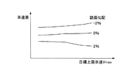
例えば、惰性走行中の車輌の減速度は、下り勾配の路面よりも平坦路、平坦路よりも上り勾配の路面の方が大きくなる。これが為、上り勾配の路面においては、惰性走行から加速走行へと切り替わったときの減速度と加速度の違いが大きくなるので、車速差を小さくして加減速の変化による違和感を運転者に感じ取らせないことが望ましい。従って、本実施例の車速差は、図3に示す如く、下り勾配の路面(例えば路面勾配−2%)よりも平坦路(路面勾配0%)、平坦路よりも上り勾配の路面(例えば路面勾配2%)の方が小さくなるようにする。また、本実施例においては、図3に示す如く、上り勾配の路面ならば惰性走行の初速たる目標上限車速Vmaxが高いほど車速差を小さくし、下り勾配の路面ならば目標上限車速Vmaxが高いほど車速差を大きくする。
For example, the deceleration of a vehicle during coasting is greater on a flat road than on a downward slope and on an upward slope than on a flat road. For this reason, on an uphill road surface, the difference between deceleration and acceleration when switching from coasting to acceleration is increased, so the difference in vehicle speed is reduced and the driver feels a sense of discomfort due to changes in acceleration / deceleration. Desirably not. Accordingly, as shown in FIG. 3, the vehicle speed difference of the present embodiment is such that the road surface is flat (
尚、路面勾配については、この技術分野における周知の方法によって求めればよく、例えば車輌前後方向加速度センサ86で検出された車輌前後方向加速度の変化から導き出すことができる。従って、本実施例のメインECU71は、走行中の車輌前後方向加速度の変化を常に観ながら路面勾配を求めるものとする。その路面勾配の情報については、新たな値が算出される度にその値へと置き換えてメインECU71のRAM等に記憶される。
The road surface gradient may be obtained by a well-known method in this technical field, and can be derived from, for example, a change in vehicle longitudinal acceleration detected by the vehicle
本実施例においては、このように目標上限車速Vmaxと目標下限車速Vminが設定されることによって、実加減速走行パターンにおける惰性走行の走行時間を導き出すことができる。つまり、その惰性走行の走行時間は、変数たる目標上限車速Vmaxと目標下限車速Vminと路面勾配とで決まるので、これら3者を明らかにすることによって求めることができる。本実施例においては、これら3者と惰性走行の走行時間の対応関係を予め実験やシミュレーションで求めたマップデータ(図示略)を用意しておき、これを用いてメインECU71の実加減速走行パターン生成手段に実加減速走行パターンにおける惰性走行の走行時間を演算させる。
In the present embodiment, by setting the target upper limit vehicle speed Vmax and the target lower limit vehicle speed Vmin in this way, it is possible to derive the coasting time in the actual acceleration / deceleration traveling pattern. That is, the traveling time of the inertia traveling is determined by the target upper limit vehicle speed Vmax, the target lower limit vehicle speed Vmin, and the road gradient, which can be obtained by clarifying these three factors. In the present embodiment, map data (not shown) for which the correspondence relationship between the travel time of these three persons and the inertia traveling is obtained in advance by experiments and simulations is prepared, and the actual acceleration / deceleration traveling pattern generation of the
一方、実加減速走行パターンにおける加速走行の走行時間については、目標上限車速Vmaxと目標下限車速Vminと路面勾配に加えて、その際の車輌の加速度の大きさによって決まる。つまり、加速走行の走行時間は、これら4者がどのような値になっているのかによって変化する。本実施例においては、その加速走行時の車輌の加速度(厳密には下記の最良加速度Gbest)をメインECU71の実加減速走行パターン生成手段に求めさせ、その加速度と目標上限車速Vmaxと目標下限車速Vminと路面勾配の4者と加速走行の走行時間の対応関係を予め実験やシミュレーションで求めたマップデータ(図示略)を用意しておき、これを用いて実加減速走行パターン生成手段に加速走行の走行時間を演算させる。
On the other hand, the travel time of acceleration travel in the actual acceleration / deceleration travel pattern is determined by the magnitude of vehicle acceleration at that time, in addition to the target upper limit vehicle speed Vmax, the target lower limit vehicle speed Vmin, and the road surface gradient. That is, the travel time of the acceleration travel changes depending on what value these four members have. In this embodiment, the acceleration (the following best acceleration G best ) of the vehicle during the acceleration traveling is obtained by the actual acceleration / deceleration traveling pattern generation means of the
ここで、加速走行時の車輌の加速度が大きすぎると、目標下限車速Vminから目標上限車速Vmaxへと素早く加速されるので、運転者は、その激しい車速の変化に違和感を覚える。一方、その加速度が小さすぎると、目標上限車速Vmaxへと到達するまでに長い時間を要するので、このときには、その間燃料が噴射され続けて燃費が悪化する。これが為、本実施例においては、運転者の違和感と燃費の悪化をバランス良く抑えることのできる加速走行時の車輌の加速度(以下、「最良加速度」という。)Gbestを設定する。本実施例においては、最良加速度Gbestと車速と路面勾配との対応関係を予め実験やシミュレーションで求めた図4に示すマップデータを用意しておき、これを用いてメインECU71の実加減速走行パターン生成手段に内燃機関10の熱効率に優れる最良加速度Gbestを演算させる。例えば、上り勾配の路面のときには、最良加速度Gbestを大きくすると、惰性走行の減速度との差が大きくなって運転者に違和感を与えやすくなる。一方、下り勾配の路面のときには、最良加速度Gbestを大きくしなければ、目標上限車速Vmaxへと到達するまでに時間がかかって燃費が悪化する。これが為、本実施例の最良加速度Gbestは、図4に示す如く、下り勾配の路面(例えば路面勾配−2%)よりも平坦路(路面勾配0%)、平坦路よりも上り勾配の路面(例えば路面勾配2%)の方が小さくなるようにする。
Here, if the acceleration of the vehicle during acceleration traveling is too large, the vehicle is quickly accelerated from the target lower limit vehicle speed Vmin to the target upper limit vehicle speed Vmax, so the driver feels uncomfortable with the drastic change in the vehicle speed. On the other hand, if the acceleration is too small, it takes a long time to reach the target upper limit vehicle speed Vmax. At this time, fuel continues to be injected and the fuel efficiency deteriorates. For this reason, in this embodiment, the acceleration (hereinafter referred to as “best acceleration”) G best during acceleration traveling that can suppress a driver's uncomfortable feeling and fuel consumption deterioration in a well-balanced manner is set. In the present embodiment, the map data shown in FIG. 4 in which the correspondence between the best acceleration G best , the vehicle speed, and the road surface gradient is obtained in advance through experiments and simulations is prepared, and the actual acceleration / deceleration running pattern of the
本実施例においては、その惰性走行の走行時間と加速走行の走行時間とを合わせたものが実加減速走行パターンにおける加減速周期(以下、「実加減速周期」という。)T1となる。このことから、実加減速走行パターンとは、その実加減速周期T1で惰性走行及び加速走行に伴う車輌の減速及び加速が行われるものであると言える。その実加減速周期T1については、メインECU71の実加減速走行パターン生成手段に演算させる。
In the present embodiment, the sum of the inertia traveling time and the acceleration traveling time is an acceleration / deceleration cycle (hereinafter referred to as “actual acceleration / deceleration cycle”) T1 in the actual acceleration / deceleration traveling pattern. From this, it can be said that the actual acceleration / deceleration traveling pattern is that the vehicle is decelerated and accelerated in accordance with inertial traveling and acceleration traveling in the actual acceleration / deceleration cycle T1. The actual acceleration / deceleration cycle T1 is calculated by the actual acceleration / deceleration running pattern generation means of the
また、本実施例においては、目標上限車速Vmaxと目標下限車速Vminと惰性走行及び加速走行の走行時間とを明らかにしてから実加減速走行パターンの具体的な生成を行う。ここでは、惰性走行と加速走行の切り替え時に急激な加速度や減速度の変化が起こらないように、図3に示す如く、惰性走行から加速走行へと移る前の減速度を徐々に小さくしていき、且つ、加速走行へと移った後の加速度を徐々に大きくしていく。更に、加速走行から惰性走行への切り替え時も同様に、加速走行から惰性走行へと移る前の加速度を徐々に小さくしていき、惰性走行へと移った後の減速度を徐々に大きくしていく。 In the present embodiment, the actual acceleration / deceleration travel pattern is specifically generated after clarifying the target upper limit vehicle speed Vmax, the target lower limit vehicle speed Vmin, and the travel time of inertial travel and acceleration travel. Here, as shown in FIG. 3, the deceleration before moving from inertial travel to acceleration travel is gradually reduced so that sudden acceleration and deceleration changes do not occur when switching between inertial travel and acceleration travel. And the acceleration after moving to acceleration running is gradually enlarged. In addition, when switching from acceleration to inertial driving, the acceleration before moving from acceleration to inertial driving is gradually reduced, and the deceleration after shifting to inertial driving is gradually increased. Go.
その生成された実加減速走行パターンからは、内燃機関10の再起動時期(加速走行開始時又はこれよりも僅かに早め)が明らかになり、且つ、再停止時期(惰性走行開始時又はこれよりも僅かに早め)も明らかになる。更に、この実加減速走行パターンからは、内燃機関10が再起動してから再停止するまでに消費される1周期当たりの燃料量を車速の変化から導き出すことができるので、実加減速走行パターンにおける燃費(以下、「実加減速走行パターン燃費」という。)Mtrealを求めることができる。
From the generated actual acceleration / deceleration travel pattern, the restart timing of the internal combustion engine 10 (at the start of acceleration travel or slightly earlier than this) is clarified, and the restart timing (at the start of inertia travel or earlier than this) Slightly earlier) will also be revealed. Further, from this actual acceleration / deceleration running pattern, the amount of fuel consumed per cycle from when the
また、加速走行中には、内燃機関10の機関動力の一部(分割動力)によって第1モータ/ジェネレータ31が発電機として作動する。これが為、このときにバッテリ41が目標充電量に達していなければ、モータ/ジェネレータECU73は、その発電電力を目標充電量に達するまでバッテリ41に充電させる。
Further, during acceleration traveling, the first motor /
ところで、この実加減速走行パターンにおける実加減速周期T1は、必ずしも車速の変化に伴う運転者の違和感を解消させるのに最適な周期であるとは限らない。つまり、加速と減速の繰り返しが短い周期で頻繁に行われた場合、運転者は、その加減速の変化で違和感を覚える。これが為、実加減速走行パターンでの走行は、その実加減速周期T1が或る値(以下、「基準加減速周期」という。)T0以上にならなければ実行させないようにする。従って、実加減速周期T1が基準加減速周期T0よりも短いときには、加減速周期を実加減速周期T1よりも基準加減速周期T0に近づけた補正加減速走行パターンの生成を行わせる。つまり、その補正加減速走行パターンとは、実加減速走行パターンの実加減速周期T1を長くしたものであり、メインECU71の補正加減速走行パターン生成手段に生成させる。
By the way, the actual acceleration / deceleration period T1 in the actual acceleration / deceleration running pattern is not necessarily an optimum period for eliminating the driver's uncomfortable feeling accompanying the change in the vehicle speed. That is, when acceleration and deceleration are frequently repeated in a short cycle, the driver feels uncomfortable with the change in acceleration / deceleration. For this reason, traveling in the actual acceleration / deceleration traveling pattern is not executed unless the actual acceleration / deceleration cycle T1 becomes a certain value (hereinafter referred to as “reference acceleration / deceleration cycle”) T0 or more. Therefore, when the actual acceleration / deceleration cycle T1 is shorter than the reference acceleration / deceleration cycle T0, a corrected acceleration / deceleration running pattern is generated in which the acceleration / deceleration cycle is closer to the reference acceleration / deceleration cycle T0 than the actual acceleration / deceleration cycle T1. That is, the corrected acceleration / deceleration running pattern is obtained by extending the actual acceleration / deceleration cycle T1 of the actual acceleration / deceleration running pattern, and is generated by the corrected acceleration / deceleration running pattern generation means of the
また、その基準加減速周期T0は、燃費の向上及び車速や車輌の加減速の変化に伴う運転者の違和感の解消の両立を図れる加減速周期であり、例えば路面勾配毎の値を予め実験やシミュレーションで求めてマップデータとして用意しておく。更に、この基準加減速周期T0については、燃費の向上を目的として予め実験等を行って設定したものであってもよく、そのような運転者の違和感の解消を目的にして予め実験等で設定したものであってもよい。この場合においても、基準加減速周期T0は、マップデータとして用意しておけばよい。また更に、この基準加減速周期T0については、運転者が車室内のスイッチ等(図示略)で好みに応じて変更できる値にしてもよい。この場合には、燃費と運転者の違和感の解消の両立が可能な加減速周期を何種類かの中から運転者に選択させるようにしてもよく、これと共に又はこれに替えて燃費の向上が可能な加減速周期や運転者の違和感の解消が可能な加減速周期を選択させるようにしてもよい。そして、この場合には、予め行った実験等に基づいてその選択パターン毎の基準加減速周期T0を設定すればよい。また、走行環境の変化や運転者の嗜好(例えば、加減速重視や燃費重視等の運転者の好み走行パターン)の変化に対応させるべく、実際の走行中の燃費を学習し、その学習値に基づいて上記のマップデータや選択パターンを新たなものへと更新させてもよい。 The reference acceleration / deceleration period T0 is an acceleration / deceleration period that can achieve both improvement in fuel efficiency and elimination of the driver's uncomfortable feeling due to changes in vehicle speed and vehicle acceleration / deceleration. Obtained by simulation and prepared as map data. Further, the reference acceleration / deceleration period T0 may be set in advance through experiments or the like for the purpose of improving fuel efficiency, and is set in advance through experiments or the like for the purpose of eliminating such a driver's uncomfortable feeling. It may be what you did. Even in this case, the reference acceleration / deceleration period T0 may be prepared as map data. Furthermore, the reference acceleration / deceleration period T0 may be set to a value that can be changed according to preference by a driver or the like (not shown) in the vehicle interior. In this case, the driver may be allowed to select from several types of acceleration / deceleration cycles that can achieve both the fuel economy and the driver's sense of incongruity. You may make it select the acceleration / deceleration period which can eliminate the possible acceleration / deceleration period and a driver | operator's uncomfortable feeling. In this case, the reference acceleration / deceleration period T0 for each selected pattern may be set based on experiments performed in advance. In addition, in order to respond to changes in the driving environment and changes in the driver's preferences (for example, the driver's preference driving pattern such as emphasis on acceleration / deceleration and fuel efficiency), the actual fuel consumption during driving is learned, and the learning value Based on this, the map data and the selection pattern may be updated to new ones.
[補正加減速走行パターン]
以下に、本実施例の補正加減速走行パターンについて説明する。本実施例の補正加減速走行パターンとしては、実加減速走行パターンに対して加速走行時の車輌の加速度を小さく補正することで加減速周期を基準加減速周期T0に近づける補正加減速走行パターン(以下、「第1補正加減速走行パターン」という。)と、実加減速走行パターンに対して惰性走行時の減速度を小さく補正することで加減速周期を基準加減速周期T0に近づける補正加減速走行パターン(以下、「第2補正加減速走行パターン」という。)と、実加減速走行パターンに対して実加減速周期中に定常車速走行を付け加えることで加減速周期を基準加減速周期T0に近づける補正加減速走行パターン(以下、「第3補正加減速走行パターン」という。)と、を例示する。
[Corrected acceleration / deceleration running pattern]
Below, the correction | amendment acceleration / deceleration running pattern of a present Example is demonstrated. As a corrected acceleration / deceleration running pattern of the present embodiment, a corrected acceleration / deceleration running pattern (hereinafter referred to as a reference acceleration / deceleration running pattern (hereinafter referred to as “acceleration / deceleration running pattern”)) is obtained by correcting the acceleration of the vehicle during acceleration running smaller than the actual acceleration / deceleration running pattern. , Referred to as “first corrected acceleration / deceleration travel pattern”) and a corrected acceleration / deceleration travel pattern in which the acceleration / deceleration period is made closer to the reference acceleration / deceleration period T0 by correcting the deceleration during inertial travel to be smaller than the actual acceleration / deceleration travel pattern. (Hereinafter referred to as a “second corrected acceleration / deceleration travel pattern”) and correction acceleration / deceleration that approximates the acceleration / deceleration period to the reference acceleration / deceleration period T0 by adding steady vehicle speed travel during the actual acceleration / deceleration period to the actual acceleration / deceleration travel pattern. A travel pattern (hereinafter referred to as a “third corrected acceleration / deceleration travel pattern”) is exemplified.
[第1補正加減速走行パターン]
先ず、第1補正加減速走行パターンについての説明を図5に基づき行う。
[First corrected acceleration / deceleration running pattern]
First, the first corrected acceleration / deceleration running pattern will be described with reference to FIG.
図5に示す第1補正加減速走行パターンは、実加減速周期T1と基準加減速周期T0の差の時間分だけ加速走行の走行時間を延長したものであり、その延長後の走行時間に見合う大きさにまで車輌の加速度を最良加速度Gbestよりも小さくしたものである。つまり、この第1補正加減速走行パターンは、実加減速走行パターンのときよりも緩やかに加速させることによって加減速周期を基準加減速周期T0にまで延長させ、これにより加減速の変化(加速走行と惰性走行の頻繁な切り替わり)に伴う運転者の違和感の解消を図るものである。 The first corrected acceleration / deceleration travel pattern shown in FIG. 5 is obtained by extending the travel time of acceleration travel by the time of the difference between the actual acceleration / deceleration cycle T1 and the reference acceleration / deceleration cycle T0, and is large enough to match the travel time after the extension. In this way, the acceleration of the vehicle is made smaller than the best acceleration G best . That is, the first corrected acceleration / deceleration travel pattern extends the acceleration / deceleration cycle to the reference acceleration / deceleration cycle T0 by accelerating more slowly than in the actual acceleration / deceleration travel pattern, thereby changing the acceleration / deceleration (acceleration travel and acceleration / deceleration). This is intended to eliminate the driver's uncomfortable feeling associated with frequent switching of inertial driving.
ここで、この第1補正加減速走行パターンは、加速走行の走行時間を延ばしているので、実加減速走行パターンよりも燃料消費量が多くなって燃費を悪化させる可能性がある。しかしながら、ここでは、多少燃費が悪くなっても運転者に不快な違和感を与えないようにする為、実加減速走行パターンでの走行で運転者が違和感を覚える可能性があるならば、実加減速走行パターンよりも第1補正加減速走行パターンが選択されるようにする。 Here, since the first corrected acceleration / deceleration travel pattern extends the travel time of the acceleration travel, there is a possibility that the fuel consumption is larger than the actual acceleration / deceleration travel pattern and the fuel consumption is deteriorated. However, here, in order to prevent the driver from feeling uncomfortable even if the fuel consumption is somewhat worse, if the driver may feel uncomfortable during driving in the actual acceleration / deceleration driving pattern, the actual acceleration / deceleration driving will occur. The first corrected acceleration / deceleration running pattern is selected rather than the pattern.
一方、運転者に違和感を与えなくする為に大幅な燃費の悪化を許容することは好ましくない。これが為、加減速走行パターンで許容し得る最悪の燃費を定めておき、第1補正加減速走行パターンの燃費(以下、「第1補正加減速走行パターン燃費」という。)Mt1がその最悪の燃費よりも悪くならないようにする。本実施例においては、その最悪の燃費となる手前の最小限の車輌の加速度(以下、「下限加速度」という。)Gminを導き出し、これを補正後の加速走行時における車輌の加速度の下限側のガード値とする。そして、その補正後の加速度が下限加速度Gmin以下のときには、その下限加速度Gminを加速走行時の最終的な加速度として設定させるようにする。従って、このときには、第1補正加減速走行パターンの加減速周期が基準加減速周期T0よりも短くなるが、多少運転者が違和感を覚えたとしても燃費の大幅な悪化を回避させるようにする。ここでは、最良加速度Gbestのときと同様に、その下限加速度Gminと目標下限車速Vminと路面勾配との対応関係を予め実験やシミュレーションで求めた図6に示すマップデータを用意しておき、これを用いてメインECU71の補正加減速走行パターン生成手段に下限加速度Gminを演算させる。 On the other hand, it is not preferable to allow a significant deterioration in fuel consumption in order not to give the driver a sense of incongruity. For this reason, the worst fuel consumption allowable in the acceleration / deceleration running pattern is determined, and the fuel consumption of the first corrected acceleration / deceleration running pattern (hereinafter referred to as “first corrected acceleration / deceleration running pattern fuel consumption”) Mt1 is the worst fuel consumption. To be no worse. In the present embodiment, the minimum vehicle acceleration (hereinafter referred to as “lower limit acceleration”) G min in front of which becomes the worst fuel consumption is derived, and this is corrected to the lower limit side of the vehicle acceleration during acceleration travel after correction. Guard value. When the corrected acceleration is equal to or lower than the lower limit acceleration G min , the lower limit acceleration G min is set as the final acceleration during acceleration traveling. Therefore, at this time, although the acceleration / deceleration period of the first corrected acceleration / deceleration running pattern is shorter than the reference acceleration / deceleration period T0, even if the driver feels somewhat uncomfortable, a significant deterioration in fuel consumption is avoided. Here, as in the case of the best acceleration G best , the map data shown in FIG. 6 in which the correspondence between the lower limit acceleration G min , the target lower limit vehicle speed Vmin, and the road surface gradient is obtained in advance through experiments and simulations is prepared. This is computed lower limit acceleration G min to correct deceleration running pattern generating means of the main ECU71 using.
また、加速走行時の最終的な加速度については、上記の補正後の加速度が下限加速度Gminよりも大きければ更に小さくしてもよい。つまり、第1補正加減速走行パターンの加減速周期については、加速走行時の加速度を上記の補正後の加速度よりも小さくし、加速走行の走行時間を図5に示す状態から更に延長することによって、基準加減速周期T0より長くしてもよい。これにより、このときの第1補正加減速走行パターンは、燃費の大幅な悪化を回避しつつも車輌の加減速の大きな変化に伴う違和感の更なる解消を図ることができる。 Also, the final acceleration during acceleration traveling can be further reduced if the acceleration after the above correction is larger than the lower acceleration limit G min. That is, for the acceleration / deceleration cycle of the first corrected acceleration / deceleration travel pattern, the acceleration during acceleration travel is made smaller than the corrected acceleration, and the travel time for acceleration travel is further extended from the state shown in FIG. The reference acceleration / deceleration period T0 may be longer. Thereby, the 1st correction | amendment acceleration / deceleration driving | running | working pattern at this time can aim at the further cancellation of the uncomfortable feeling accompanying the big change of the acceleration / deceleration of a vehicle, avoiding the significant deterioration of a fuel consumption.
この第1補正加減速走行パターンを生成する際には、実加減速走行パターンのときと同様に、惰性走行と加速走行の切り替え時に急激な加速度や減速度の変化が起こらないよう調整する。そして、第1補正加減速走行パターン燃費Mt1については、実加減速走行パターンのときと同様に、その生成された第1補正加減速走行パターンの車速変化に基づいた1周期当たりの内燃機関10の起動期間中における燃料消費量を導き出して求める。
When the first corrected acceleration / deceleration running pattern is generated, adjustment is performed so that a sudden change in acceleration or deceleration does not occur when switching between inertial running and acceleration running, as in the case of the actual acceleration / deceleration running pattern. As for the first corrected acceleration / deceleration running pattern fuel efficiency Mt1, the
この第1補正加減速走行パターンにおいても、加速走行中にバッテリ41が目標充電量に達していなければ、モータ/ジェネレータECU73は、第1モータ/ジェネレータ31での発電電力を目標充電量に達するまでバッテリ41に充電させる。その際、第1補正加減速走行パターンにおいては、実加減速走行パターンのときよりも加速走行時の加速度が小さく補正されているので、内燃機関10の起動時間の延長に伴って第1モータ/ジェネレータ31での発電電力量が実加減速走行パターンのときに比べて増加する。これが為、本実施例においては、その補正後の加速度に対応させた大きな値へと目標充電量設定手段に目標充電量を再設定させる。これにより、第1補正加減速走行パターンが選択されたときには、実加減速走行パターンのときよりも多くの電力をバッテリ41に充電することができるようになる。
Even in the first corrected acceleration / deceleration running pattern, if the
[第2補正加減速走行パターン]
次に、第2補正加減速走行パターンについての説明を図7に基づき行う。
[Second corrected acceleration / deceleration running pattern]
Next, the second correction acceleration / deceleration running pattern will be described with reference to FIG.
図7に示す第2補正加減速走行パターンは、実加減速周期T1と基準加減速周期T0の差の時間分だけ惰性走行の走行時間を延長したものであり、その延長後の走行時間に見合う大きさにまで車輌の減速度を小さくしたものである。本実施例においては、その為に、惰性走行中に第2モータ/ジェネレータ32を電動機として作動させて電動機動力を加える。この第2補正加減速走行パターンは、実加減速走行パターンのときよりも緩やかに減速させることによって加減速周期を基準加減速周期T0にまで延長させ、これにより加減速の変化(加速走行と惰性走行の頻繁な切り替わり)に伴う運転者の違和感の解消を図るものである。ここで、メインECU71の補正加減速走行パターン生成手段は、その延長後の惰性走行の走行時間を実現可能な電動機動力を発生させる第2モータ/ジェネレータ32への供給電力を演算する。その供給電力は、下り勾配よりも上り勾配のときに大きくする。
The second corrected acceleration / deceleration traveling pattern shown in FIG. 7 is obtained by extending the inertial traveling time by the time difference between the actual acceleration / deceleration cycle T1 and the reference acceleration / deceleration cycle T0, and is large enough to match the travel time after the extension. This is a reduction in vehicle deceleration. In this embodiment, for this purpose, the motor power is applied by operating the second motor / generator 32 as an electric motor during inertial running. In this second corrected acceleration / deceleration running pattern, the acceleration / deceleration cycle is extended to the reference acceleration / deceleration cycle T0 by decelerating more slowly than in the actual acceleration / deceleration running pattern, thereby changing the acceleration / deceleration (acceleration running and inertia running). This is intended to eliminate the driver's uncomfortable feeling that accompanies frequent switching. Here, the corrected acceleration / deceleration travel pattern generation means of the
この第2補正加減速走行パターンは、実加減速走行パターンに対して加速走行の走行時間を変えていないので(換言するならば、最良加速度Gbestのままなので)、加減速走行しているときのみを観れば、燃費が実加減速走行パターンのときと殆ど変わらない。しかしながら、この第2補正加減速走行パターンにおいては、惰性走行中にバッテリ41の電力を利用して第2モータ/ジェネレータ32を電動機として作動させるので、バッテリ41の蓄電量の低下を防ぐべく、少なくとも惰性走行時の第2モータ/ジェネレータ32の作動に伴うバッテリ41の消費電力を加減速走行後に回収しておく必要がある。そして、その消費電力の回収には内燃機関10の機関動力の一部(分割動力)が利用されるので、この回収時も含めた全体の走行状態を観察した場合には、燃費が悪化してしまう。つまり、この内燃機関10による発電電力(換言すれば、惰性走行時の第2モータ/ジェネレータ32への供給電力)も考慮に入れた第2補正加減速走行パターンの燃費(以下、「第2補正加減速走行パターン燃費」という。)Mt2は、実加減速走行パターン燃費Mtrealよりも悪化することになる。その第2補正加減速走行パターン燃費Mt2については、第2補正加減速走行パターンの車速変化に基づいた1周期当たりの内燃機関10の起動期間中における燃料消費量と、その1周期当たりの第2モータ/ジェネレータ32への供給電力を回収させる為に必要な内燃機関10の燃料量と、を導き出し、これらに基づいて求める。尚、実際にはその消費電力の一部が加速走行中の第1モータ/ジェネレータ31の発電電力によって回収されているが、その発電電力は、実加減速走行パターンにおいても加速走行中に作られているので、燃費の悪化という点では変わりない。
This second corrected acceleration / deceleration running pattern does not change the running time of acceleration running with respect to the actual acceleration / deceleration running pattern (in other words, it remains the best acceleration G best ), and therefore only during acceleration / deceleration running. , The fuel efficiency is almost the same as in the actual acceleration / deceleration running pattern. However, in this second corrected acceleration / deceleration running pattern, the second motor / generator 32 is operated as an electric motor using the electric power of the
ここで、その第2補正加減速走行パターン燃費Mt2の悪化が許容できる範囲(上述した加減速走行パターンで許容し得る最悪の燃費を悪化の限界とする)の場合には、第2モータ/ジェネレータ32への供給電力及び電力供給時間を増やして、惰性走行の走行時間を更に延長してもよい。つまり、この第2補正加減速走行パターンの加減速周期については、惰性走行の走行時間を図7に示す状態から更に延長することによって、基準加減速周期T0より長くしてもよい。これにより、このときの第2補正加減速走行パターンは、燃費の大幅な悪化を回避しつつも車輌の加減速の大きな変化に伴う違和感の更なる解消を図ることができる。 Here, in the case where the deterioration of the second corrected acceleration / deceleration running pattern fuel consumption Mt2 is permissible (the worst fuel economy allowable in the above-described acceleration / deceleration running pattern is the limit of deterioration), the second motor / generator It is also possible to further extend the running time of coasting by increasing the power supplied to 32 and the power supply time. That is, the acceleration / deceleration cycle of the second corrected acceleration / deceleration travel pattern may be longer than the reference acceleration / deceleration cycle T0 by further extending the coasting travel time from the state shown in FIG. As a result, the second corrected acceleration / deceleration running pattern at this time can further eliminate the uncomfortable feeling associated with a large change in the acceleration / deceleration of the vehicle while avoiding a significant deterioration in fuel consumption.
この第2補正加減速走行パターンを生成する際には、実加減速走行パターンのときと同様に、惰性走行と加速走行の切り替え時に急激な車輌前後方向加速度の変化が起こらないよう調整する。 When the second corrected acceleration / deceleration running pattern is generated, adjustment is performed so that a sudden change in the vehicle longitudinal acceleration does not occur when switching between inertial running and acceleration running, as in the case of the actual acceleration / deceleration running pattern.
[第3補正加減速走行パターン]
次に、第3補正加減速走行パターンについて説明を図8に基づき行う。
[Third corrected acceleration / deceleration running pattern]
Next, the third correction acceleration / deceleration running pattern will be described with reference to FIG.
図8に示す第3補正加減速走行パターンは、実加減速周期T1と基準加減速周期T0の差の時間分だけ実加減速走行パターンの実加減速周期中に定常車速走行を付加したものである。つまり、この第3補正加減速走行パターンは、定常車速走行の付加によって加減速周期を基準加減速周期T0にまで延長させ、これにより加減速の変化(加速走行と惰性走行の頻繁な切り替わり)に伴う運転者の違和感の解消を図るものである。 The third corrected acceleration / deceleration running pattern shown in FIG. 8 is obtained by adding steady vehicle speed running during the actual acceleration / deceleration cycle of the actual acceleration / deceleration running pattern for the time difference between the actual acceleration / deceleration cycle T1 and the reference acceleration / deceleration cycle T0. In other words, this third corrected acceleration / deceleration running pattern extends the acceleration / deceleration period to the reference acceleration / deceleration period T0 by adding steady vehicle speed running, thereby changing the acceleration / deceleration (frequent switching between acceleration running and inertia running). It is intended to eliminate the driver's uncomfortable feeling.
具体的に、この第3補正加減速走行パターンにおいては、目標下限車速Vminでの定常車速走行(以下、「低速側定常車速走行」という。)と目標上限車速Vmaxでの定常車速走行(以下、「高速側定常車速走行」という。)の内の少なくとも何れか一方を付け加える。その低速側定常車速走行については、惰性走行から加速走行へと移る際に、目標下限車速Vminに到達した時点で第2モータ/ジェネレータ32の電動機動力を利用して実現させる。他方、高速側定常車速走行については、加速走行から惰性走行へと移る際に、目標上限車速Vmaxに到達した時点で内燃機関10の機関動力を利用して実現させる。
Specifically, in this third corrected acceleration / deceleration running pattern, steady vehicle speed running at the target lower limit vehicle speed Vmin (hereinafter referred to as “low speed side steady vehicle speed running”) and steady vehicle speed running at the target upper limit vehicle speed Vmax (hereinafter referred to as “following”). At least one of “high speed side steady vehicle speed traveling”) is added. The low-speed steady vehicle speed traveling is realized by using the motor power of the second motor / generator 32 when the target lower limit vehicle speed Vmin is reached when shifting from inertia traveling to acceleration traveling. On the other hand, the high-speed steady vehicle speed traveling is realized using the engine power of the
この第3補正加減速走行パターンを生成する際には、惰性走行から低速側定常車速走行へと移る前の車輌前後方向加速度(減速度)が徐々に小さくなり、且つ、その低速側定常車速走行から加速走行へと移った後の車輌前後方向加速度(加速度)が徐々に大きくなるようにする。また、加速走行から高速側定常車速走行へと移る前の車輌前後方向加速度(加速度)については徐々に小さくしていき、その高速側定常車速走行から惰性走行へと移った後の車輌前後方向加速度(減速度)については徐々に大きくしていく。 When the third corrected acceleration / deceleration running pattern is generated, the vehicle longitudinal acceleration (deceleration) before the transition from inertial running to low-speed steady vehicle speed running is gradually reduced, and the low-speed steady vehicle speed running is performed. The vehicle longitudinal acceleration (acceleration) after the shift from acceleration to acceleration is gradually increased. In addition, the vehicle longitudinal acceleration (acceleration) before the transition from the acceleration travel to the high-speed steady vehicle speed travel is gradually reduced, and the vehicle longitudinal acceleration after the transition from the high-speed steady vehicle travel to the inertia travel (Deceleration) is gradually increased.
本実施例においては、低速側定常車速走行と高速側定常車速走行の双方を付加して実加減速周期T1と基準加減速周期T0の差の時間分を埋めさせる。例えば、その低速側定常車速走行と高速側定常車速走行の夫々の走行時間の配分については、低速側定常車速走行によって消費されるバッテリ41の電力と高速側定常車速走行によって内燃機関10の機関動力で発電される電力とが均等になるように設定すればよい。これにより、この場合には、バッテリ41の蓄電量の低下を抑えることができるので、バッテリ41の蓄電量を元に戻す為の内燃機関10の運転を第3補正加減速走行パターンでの走行後に行わずとも済み、その内燃機関10の運転に伴う燃費の悪化を防ぐことができる。
In the present embodiment, both the low speed side steady vehicle speed running and the high speed side steady vehicle speed running are added to fill the time difference between the actual acceleration / deceleration period T1 and the reference acceleration / deceleration period T0. For example, with respect to the distribution of the traveling time of each of the low speed side steady vehicle speed traveling and the high speed side steady vehicle speed traveling, the power of the
また、そのときの第3補正加減速走行パターンの燃費(以下、「第3補正加減速走行パターン燃費」という。)Mt3については、第3補正加減速走行パターンの車速変化に基づいた1周期当たりの内燃機関10の加速走行中における燃料消費量と、1周期当たりの低速側定常車速走行における第2モータ/ジェネレータ32への供給電力を回収する為に必要な内燃機関10の燃料量又は1周期当たりの高速側定常車速走行における内燃機関10の燃料消費量と、を導き出し、これらに基づいて求めればよい。
Further, the fuel efficiency of the third corrected acceleration / deceleration travel pattern (hereinafter referred to as “third corrected acceleration / deceleration travel pattern fuel efficiency”) Mt3 at that time per cycle based on the vehicle speed change of the third corrected acceleration / deceleration travel pattern. Of the
更に、その第3補正加減速走行パターン燃費Mt3の悪化が許容できる範囲(上述した加減速走行パターンで許容し得る最悪の燃費を悪化の限界とする)の場合には、低速側定常車速走行と高速側定常車速走行の夫々の走行時間を更に延長してもよい。つまり、この第3補正加減速走行パターンの加減速周期については、その夫々の走行時間を図8に示す状態から更に延長することによって、基準加減速周期T0より長くしてもよい。これにより、このときの第3補正加減速走行パターンは、燃費の大幅な悪化を回避しつつ車輌の加減速の大きな変化に伴う違和感の更なる解消を図ることができる。 Further, in the case where the deterioration of the third corrected acceleration / deceleration running pattern fuel consumption Mt3 can be allowed (the worst fuel consumption allowed in the acceleration / deceleration running pattern described above is set as a deterioration limit), Each traveling time of the high-speed side steady vehicle speed traveling may be further extended. That is, the acceleration / deceleration cycle of the third corrected acceleration / deceleration running pattern may be longer than the reference acceleration / deceleration cycle T0 by further extending the respective running times from the state shown in FIG. Thereby, the 3rd correction | amendment acceleration / deceleration driving | running | working pattern at this time can aim at the further cancellation of the uncomfortable feeling accompanying the big change of the acceleration / deceleration of a vehicle, avoiding the significant deterioration of a fuel consumption.
本実施例においては、上述したこれらの補正加減速走行パターン(第1補正加減速走行パターン,第2補正加減速走行パターン及び第3補正加減速走行パターン)の中から最も燃費の良好なものを最良加減速走行パターンとして設定する。その最良加減速走行パターンとは、燃費の向上と車速や車輌の加減速に伴う運転者への不快な違和感の抑制を両立させた加減速走行パターンのことである。 In the present embodiment, the above-described corrected acceleration / deceleration running pattern (first corrected acceleration / deceleration running pattern, second corrected acceleration / deceleration running pattern, and third corrected acceleration / deceleration running pattern) having the best fuel efficiency is selected. Set as the best acceleration / deceleration running pattern. The best acceleration / deceleration running pattern is an acceleration / deceleration running pattern that achieves both improvement in fuel efficiency and suppression of unpleasant discomfort to the driver due to vehicle speed and acceleration / deceleration of the vehicle.
ここではその最良加減速走行パターンで車輌を走行させてもよいのだが、運転者の違和感の解消という観点からすれば、これを最も解消できるのは一定車速を維持する定常車速走行パターンであり、この定常車速走行パターンについても走行パターンの候補に挙げる方が好ましい。しかしながら、その定常車速走行パターンでの走行は、アクセルオフ後においても車速を一定に保つ為に、内燃機関10や電動機として作動させた第2モータ/ジェネレータ32の動力を駆動輪W,Wに伝える必要がある。そして、その走行中には内燃機関10の機関動力の為に燃料が消費され、また、その走行中の第2モータ/ジェネレータ32の電動機動力の為に消費されたバッテリ41の電力を回収すべく後ほど内燃機関10で燃料が消費されるので、この定常車速走行パターンについても燃費(以下、「定常車速走行パターン燃費」という。)Mconstを考慮に入れなければならない。そこで、本実施例のメインECU71の走行パターン設定手段には、その定常車速走行パターン燃費Mconstと最良加減速走行パターンの燃費(以下、「最良加減速走行パターン燃費」という。)Mtbestを比較して、燃費に優れる方の走行パターンを採用させるようにする。尚、一定車速を維持する為の動力については、下り勾配よりも平坦路、平坦路よりも上り勾配のときに大きくしなければならない。
In this case, the vehicle may be driven with the best acceleration / deceleration driving pattern, but from the viewpoint of resolving the driver's uncomfortable feeling, it is the steady vehicle speed driving pattern that maintains a constant vehicle speed. It is preferable to list the steady vehicle speed travel pattern as a travel pattern candidate. However, the traveling in the steady vehicle speed traveling pattern transmits the power of the second motor / generator 32 operated as the
ここで、本実施例の定常車速走行パターンにおける定常車速Vconstとしては、上述した目標上限車速Vmaxと目標下限車速Vminの中間の車速を設定する。また、定常車速走行パターン燃費Mconstについては、所定時間(ここでは、便宜上、上述した基準加減速周期T0に合わせる。)当たりの内燃機関10の燃料消費量や、その所定時間当たりの第2モータ/ジェネレータ32への供給電力を回収する為に必要な内燃機関10の燃料量を導き出して求める。この定常車速走行パターンの生成や定常車速走行パターン燃費Mconstの演算は、メインECU71の定常車速走行パターン生成手段に実行させる。
Here, as the steady vehicle speed V const in the steady vehicle speed traveling pattern of this embodiment, an intermediate vehicle speed between the above-described target upper limit vehicle speed Vmax and target lower limit vehicle speed Vmin is set. Further, with respect to the steady vehicle speed travel pattern fuel consumption M const , the fuel consumption of the
以下に、本実施例の車輌走行制御装置の走行パターン設定動作について図9及び図10のフローチャートを用いて説明する。 Hereinafter, the travel pattern setting operation of the vehicle travel control apparatus of the present embodiment will be described with reference to the flowcharts of FIGS.
先ず、メインECU71は、図9のフローチャートに示すように、アクセル開度センサ84から検出されたアクセル開度を観てアクセルオフか否かを判断する(ステップST1)。かかる判断については、常に行わせるものとする。
First, as shown in the flowchart of FIG. 9, the
このメインECU71は、アクセルオフになっていなければ、本動作を一旦終える。一方、アクセルオフとの判断が為された場合、メインECU71の実加減速走行パターン生成手段は、RAM等に記憶された路面勾配の情報を読み込む(ステップST2)。
If the accelerator is not turned off, the
また、この実加減速走行パターン生成手段は、目標上限車速Vmaxと目標下限車速Vminの設定を行う(ステップST3)。その際、メインECU71は、アクセルオフが検知された際の車速を目標上限車速Vmaxとする。また、このメインECU71は、その目標上限車速Vmaxと上記ステップST2の路面勾配の情報を図3のマップデータに照らし合わせて車速差を読み込む。そして、メインECU71は、その車速差を目標上限車速Vmaxから引いて求めた車速を目標下限車速Vminとする。
Further, the actual acceleration / deceleration running pattern generating means sets the target upper limit vehicle speed Vmax and the target lower limit vehicle speed Vmin (step ST3). At that time, the
また、実加減速走行パターン生成手段は、上記ステップST2の路面勾配の情報と上記ステップST3の目標上限車速Vmax及び目標下限車速Vminに基づいて、実加減速走行パターンにおける加速走行時の最良加速度Gbestを求める(ステップST4)。 Further, the actual acceleration / deceleration travel pattern generation means obtains the best acceleration G best during acceleration travel in the actual acceleration / deceleration travel pattern based on the road surface gradient information in step ST2 and the target upper limit vehicle speed Vmax and target lower limit vehicle speed Vmin in step ST3. Obtained (step ST4).
また、実加減速走行パターン生成手段は、実加減速走行パターンにおける実加減速周期T1の演算を行う(ステップST5)。その際、実加減速走行パターン生成手段は、上記ステップST2の路面勾配の情報と上記ステップST3の目標上限車速Vmax及び目標下限車速Vminに基づいて、惰性走行の走行時間を求める。更に、この実加減速走行パターン生成手段は、上記ステップST2の路面勾配の情報,上記ステップST3の目標上限車速Vmax及び目標下限車速Vmin並びに上記ステップST4の最良加速度Gbestに基づいて、加速走行の走行時間を求める。そして、メインECU71は、その惰性走行と加速走行の夫々の走行時間を加算して実加減速周期T1を導き出す。
Further, the actual acceleration / deceleration running pattern generation means calculates the actual acceleration / deceleration period T1 in the actual acceleration / deceleration running pattern (step ST5). At that time, the actual acceleration / deceleration traveling pattern generation means obtains the traveling time of inertial traveling based on the road surface gradient information in step ST2 and the target upper limit vehicle speed Vmax and target lower limit vehicle speed Vmin in step ST3. Further, the actual acceleration / deceleration travel pattern generation means is configured to perform acceleration travel based on the road surface gradient information in step ST2, the target upper limit vehicle speed Vmax and the target lower limit vehicle speed Vmin in step ST3, and the best acceleration G best in step ST4. Ask for time. Then, the
このようにして目標上限車速Vmax,目標下限車速Vmin及び実加減速周期T1(惰性走行の走行時間と加速走行の走行時間)を明らかにした後、メインECU71は、これらを用いて例えば図2に示す実加減速走行パターンの生成を行う(ステップST6)。その際、この実加減速走行パターン生成手段は、惰性走行から加速走行へと移る前の車輌の減速度を徐々に小さくし、加速走行へと移った後の車輌の加速度を最良加速度Gbestへと滑らかに繋がるよう徐々に大きくする。また、この実加減速走行パターン生成手段は、加速走行から惰性走行へと移る前の車輌の加速度を最良加速度Gbestから徐々に小さくし、惰性走行へと移った後の車輌の減速度を徐々に大きくする。これにより、惰性走行と加速走行の切り替えのときの急激な加速度や減速度の変化を抑えることができ、急激な車輌の加減速の変化による運転者に対しての不快な違和感を回避できる。
After clarifying the target upper limit vehicle speed Vmax, the target lower limit vehicle speed Vmin, and the actual acceleration / deceleration period T1 (the travel time of inertial travel and the travel time of acceleration travel), the
実加減速走行パターン生成手段は、実加減速走行パターンの生成を行った後、実加減速走行パターン燃費Mtrealの演算を行う(ステップST7)。その際、この実加減速走行パターン生成手段は、その生成された実加減速走行パターンに基づいて、惰性走行と加速走行からなる1周期当たりの内燃機関10の燃料消費量を求めると共に、その1周期の間の車輌の走行距離を求める。そして、この実加減速走行パターン生成手段は、その燃料消費量と走行距離に基づいて実加減速走行パターン燃費Mtrealを求める。
The actual acceleration / deceleration travel pattern generation means calculates the actual acceleration / deceleration travel pattern fuel consumption Mt real after generating the actual acceleration / deceleration travel pattern (step ST7). At this time, the actual acceleration / deceleration running pattern generation means obtains the fuel consumption amount of the
しかる後、メインECU71の加減速周期比較手段は、その実加減速走行パターンの実加減速周期T1と上述した基準加減速周期T0の比較を行う(ステップST8)。
Thereafter, the acceleration / deceleration cycle comparison means of the
このステップST8において実加減速周期T1が基準加減速周期T0以上と判定された場合(つまり、運転者に違和感を与えるほど車輌の加減速を大きく変化させることのない適切な加減速周期であると判断された場合)、メインECU71の最良加減速走行パターン設定手段は、後述するステップST10に進んで実加減速走行パターン燃費Mtrealを最良加減速走行パターン燃費Mtbestに設定する。この場合、最良加減速走行パターン設定手段は、後述するステップST11において、実加減速走行パターンを最良加減速走行パターンとして設定する。
If it is determined in step ST8 that the actual acceleration / deceleration period T1 is greater than or equal to the reference acceleration / deceleration period T0 (that is, it is determined that the acceleration / deceleration period is an appropriate acceleration / deceleration period that does not significantly change the acceleration / deceleration of the vehicle to the driver) If so, the best acceleration / deceleration running pattern setting means of the
一方、上記ステップST8において実加減速周期T1が基準加減速周期T0よりも短いと判定された場合(つまり、車輌の加減速の変化が大きくて、運転者に違和感を与える虞のある加減速周期であると判断された場合)、メインECU71の補正加減速走行パターン生成手段は、その違和感を抑えることが可能な補正加減速走行パターンの生成及び燃費の演算を行う(ステップST9)。このステップST9については、図10のフローチャートを用いて詳述する。
On the other hand, if it is determined in step ST8 that the actual acceleration / deceleration period T1 is shorter than the reference acceleration / deceleration period T0 (that is, the acceleration / deceleration period has a large change in the acceleration / deceleration of the vehicle and may cause the driver to feel uncomfortable). When it is determined that there is a correction), the corrected acceleration / deceleration running pattern generation means of the
この補正加減速走行パターン生成手段は、第1補正加減速走行パターンの生成を行う(ステップST9A)。 The corrected acceleration / deceleration running pattern generation unit generates a first corrected acceleration / deceleration running pattern (step ST9A).
その際、補正加減速走行パターン生成手段は、実加減速周期T1と基準加減速周期T0の差を求め、その差の時間分だけ実加減速走行パターンに対して加速走行の走行時間を延長させることのできる加速走行時の車輌の加速度を求める。この演算時には、加速走行時の車輌の加速度が上述したように最良加速度Gbestよりも小さな値として求められる。ここで、補正加減速走行パターン生成手段は、その加速走行時の車輌の加速度と上述した下限加速度Gminとを比較し、その比較結果に基づいて加速走行時の最終的な車輌の加速度を決める。つまり、上述したように、算出された加速走行時の車輌の加速度が下限加速度Gminよりも大きいときには、その加速走行時の車輌の加速度又はこれよりも更に小さな加速度を加速走行時における最終的な車輌の加速度とする。一方、算出された加速走行時の車輌の加速度が下限加速度Gmin以下のときには、その下限加速度Gminを加速走行時の最終的な車輌の加速度とする。従って、加速走行の走行時間は、その加速走行時の最終的な車輌の加速度によって異なる長さになる。 At this time, the corrected acceleration / deceleration running pattern generation means obtains the difference between the actual acceleration / deceleration cycle T1 and the reference acceleration / deceleration cycle T0, and extends the running time of the acceleration running with respect to the actual acceleration / deceleration running pattern by the difference time. The acceleration of the vehicle during acceleration running that can be obtained is obtained. At the time of this calculation, the acceleration of the vehicle during acceleration traveling is obtained as a value smaller than the best acceleration G best as described above. Here, the corrected acceleration / deceleration running pattern generation means compares the acceleration of the vehicle during the accelerated running and the above-described lower limit acceleration Gmin, and determines the final vehicle acceleration during the accelerated running based on the comparison result. . That is, as described above, when the calculated acceleration of the vehicle at the time of acceleration traveling is larger than the lower limit acceleration G min , the vehicle acceleration at the time of acceleration traveling or an acceleration smaller than this is set to the final value at the time of acceleration traveling. The acceleration of the vehicle. On the other hand, when the vehicle acceleration at the time of the calculated acceleration running is less than the lower acceleration limit G min is a final vehicle acceleration during the acceleration running the lower acceleration limit G min. Therefore, the travel time of the acceleration travel varies depending on the final vehicle acceleration during the acceleration travel.
この補正加減速走行パターン生成手段は、実加減速走行パターンのときと同じ目標上限車速Vmax,目標下限車速Vmin及び惰性走行の走行時間と今回延長した加速走行の走行時間とを用いて、例えば図5に示す第1補正加減速走行パターンを生成する。つまり、この第1補正加減速走行パターンは、加速走行の走行時間を延ばすことによって、実加減速走行パターンよりも加減速周期の延長を図っている。従って、この第1補正加減速走行パターンは、実加減速走行パターンが加減速周期の短さ故に違和感を運転者に与えてしまうものならば、その違和感の抑制を図ることができる。 This corrected acceleration / deceleration travel pattern generation means uses the same target upper limit vehicle speed Vmax, target lower limit vehicle speed Vmin, inertia travel time and the acceleration travel time extended this time as in the actual acceleration / deceleration travel pattern, for example, FIG. The first corrected acceleration / deceleration running pattern shown in FIG. In other words, this first corrected acceleration / deceleration travel pattern extends the acceleration / deceleration cycle more than the actual acceleration / deceleration travel pattern by extending the travel time of acceleration travel. Therefore, the first corrected acceleration / deceleration running pattern can suppress the uncomfortable feeling if the actual acceleration / deceleration running pattern gives the driver an uncomfortable feeling due to the short acceleration / deceleration cycle.
ここで、その生成の際には、惰性走行から加速走行へと移る前の車輌の減速度を徐々に小さくし、加速走行へと移った後の車輌の加速度を加速走行時の最終的な車輌の加速度へと滑らかに繋がるよう徐々に大きくする。また、この際には、加速走行から惰性走行へと移る前の車輌の加速度を加速走行時における最終的な車輌の加速度から徐々に小さくし、惰性走行へと移った後の車輌の減速度を徐々に大きくする。これにより、惰性走行と加速走行の切り替えのときの急激な車輌の加速度や減速度の変化を抑えることができ、急激な車輌の加減速の変化による運転者に対しての不快な違和感を回避できる。 Here, at the time of generation, the deceleration of the vehicle before moving from inertial running to acceleration running is gradually reduced, and the acceleration of the vehicle after moving to acceleration running is the final vehicle during acceleration running. Gradually increase it so that it is smoothly connected to the acceleration. Also, in this case, the acceleration of the vehicle before moving from the acceleration running to the inertia running is gradually reduced from the final vehicle acceleration at the acceleration running, and the deceleration of the vehicle after moving to the inertia running is reduced. Increase gradually. As a result, it is possible to suppress sudden changes in the acceleration and deceleration of the vehicle when switching between inertial driving and acceleration driving, and to avoid an uncomfortable feeling of incongruity for the driver due to a sudden change in the acceleration / deceleration of the vehicle. .
この補正加減速走行パターン生成手段は、この第1補正加減速走行パターンの生成を行った後、第1補正加減速走行パターン燃費Mt1の演算を行う(ステップST9B)。その際、この補正加減速走行パターン生成手段は、その生成された第1補正加減速走行パターンに基づいて、惰性走行と加速走行からなる1周期当たりの内燃機関10の燃料消費量を求めると共に、その1周期の間の車輌の走行距離を求める。そして、この補正加減速走行パターン生成手段は、その燃料消費量と走行距離に基づいて第1補正加減速走行パターン燃費Mt1を求める。
The corrected acceleration / deceleration running pattern generation means calculates the first corrected acceleration / deceleration running pattern fuel consumption Mt1 after generating the first corrected acceleration / deceleration running pattern (step ST9B). At this time, the corrected acceleration / deceleration running pattern generation means obtains the fuel consumption amount of the
また、補正加減速走行パターン生成手段は、第2補正加減速走行パターンの生成を行う(ステップST9C)。 Further, the corrected acceleration / deceleration running pattern generation means generates a second corrected acceleration / deceleration running pattern (step ST9C).
その際、補正加減速走行パターン生成手段は、実加減速周期T1と基準加減速周期T0の差を求め、その差の時間分だけ実加減速走行パターンに対して惰性走行の走行時間を延長させることのできる第2モータ/ジェネレータ32の電動機動力を求める。この場合には、その電動機動力を発生させるに十分なバッテリ41の供給電力についても演算する。そして、この補正加減速走行パターン生成手段は、実加減速走行パターンのときと同じ目標上限車速Vmax,目標下限車速Vmin及び加速走行の走行時間と今回延長した惰性走行の走行時間とを用いて、例えば図7に示す第2補正加減速走行パターンを生成する。つまり、この第2補正加減速走行パターンは、惰性走行の走行時間を延ばすことによって、実加減速走行パターンよりも加減速周期の延長を図っている。従って、この第2補正加減速走行パターンは、実加減速走行パターンが加減速周期の短さ故に違和感を運転者に与えてしまうものならば、その違和感の抑制を図ることができる。
At this time, the corrected acceleration / deceleration running pattern generation means obtains a difference between the actual acceleration / deceleration cycle T1 and the reference acceleration / deceleration cycle T0, and extends the inertial running time with respect to the actual acceleration / deceleration running pattern by the difference time. The electric power of the second motor / generator 32 that can be obtained is obtained. In this case, the power supplied to the
ここで、その生成の際には、惰性走行から加速走行へと移る前の車輌の減速度を徐々に小さくし、加速走行へと移った後の車輌の加速度を最良加速度Gbestへと滑らかに繋がるよう徐々に大きくする。また、この際には、加速走行から惰性走行へと移る前の車輌の加速度を最良加速度Gbestから徐々に小さくし、惰性走行へと移った後の車輌の減速度を徐々に大きくする。これにより、惰性走行と加速走行の切り替えのときの急激な車輌の加速度や減速度の変化を抑えることができ、急激な車輌の加減速の変化による運転者に対しての不快な違和感を回避できる。 Here, at the time of the generation, the deceleration of the vehicle before moving from inertial running to acceleration running is gradually reduced, and the acceleration of the vehicle after moving to acceleration running is smoothed to the best acceleration G best . Gradually increase to connect. At this time, the acceleration of the vehicle before the transition from the acceleration traveling to the inertia traveling is gradually decreased from the best acceleration G best , and the deceleration of the vehicle after the transition to the inertia traveling is gradually increased. As a result, it is possible to suppress sudden changes in the acceleration and deceleration of the vehicle when switching between inertial driving and acceleration driving, and to avoid an uncomfortable feeling of incongruity for the driver due to a sudden change in the acceleration / deceleration of the vehicle. .
この補正加減速走行パターン生成手段は、この第2補正加減速走行パターンの生成を行った後、第2補正加減速走行パターン燃費Mt2の演算を行う(ステップST9D)。その際、この補正加減速走行パターン生成手段は、その生成された第2補正加減速走行パターンに基づいて、惰性走行と加速走行からなる1周期当たりの内燃機関10の燃料消費量を求めると共に、その1周期当たりの第2モータ/ジェネレータ32への供給電力の回収に必要な内燃機関10の燃料量を求め、更にその1周期の間の車輌の走行距離を求める。そして、このメインECU71は、その燃料消費量と燃料量と走行距離に基づいて第2補正加減速走行パターン燃費Mt2を求める。
The corrected acceleration / deceleration running pattern generation means calculates the second corrected acceleration / deceleration running pattern fuel consumption Mt2 after generating the second corrected acceleration / deceleration running pattern (step ST9D). At this time, the corrected acceleration / deceleration running pattern generation means obtains the fuel consumption amount of the
ここで、その内燃機関10の燃料量については、次の様にして求める。先ず、補正加減速走行パターン生成手段は、その1周期当たりの第2モータ/ジェネレータ32への供給電力と同等の電力を第1モータ/ジェネレータ31で発電させることのできる分割動力を求め、その分割動力を第1モータ/ジェネレータ31に伝える為の内燃機関10の機関動力を求める。そして、この補正加減速走行パターン生成手段は、その機関動力を出力する為に必要な内燃機関10の燃料量を求める。この燃料量が1周期当たりの第2モータ/ジェネレータ32への供給電力の回収に必要な内燃機関10の燃料量となる。
Here, the fuel amount of the
また、補正加減速走行パターン生成手段は、第3補正加減速走行パターンの生成を行う(ステップST9E)。 Further, the corrected acceleration / deceleration running pattern generation means generates a third corrected acceleration / deceleration running pattern (step ST9E).
その際、補正加減速走行パターン生成手段は、実加減速周期T1と基準加減速周期T0の差を求め、その差の時間分だけ実加減速走行パターンの実加減速周期中に高速側定常車速走行と低速側定常車速走行を付け加える。つまり、ここで生成される第3補正加減速走行パターンは、その時間分を高速側定常車速走行の走行時間と低速側定常車速走行の走行時間とで配分して埋めることによって、実加減速走行パターンよりも加減速周期の延長を図っている。従って、この第3補正加減速走行パターンは、実加減速走行パターンが加減速周期の短さ故に違和感を運転者に与えてしまうものならば、その違和感の抑制を図ることができる。 At that time, the corrected acceleration / deceleration running pattern generation means obtains a difference between the actual acceleration / deceleration cycle T1 and the reference acceleration / deceleration cycle T0, and the high-speed side steady vehicle speed running and the low speed during the actual acceleration / deceleration cycle of the actual acceleration / deceleration running pattern by the time of the difference. Add side steady vehicle speed driving. In other words, the third corrected acceleration / deceleration travel pattern generated here is the actual acceleration / deceleration travel pattern by allocating and burying the time by the travel time of the high speed side steady vehicle speed travel and the travel time of the low speed side steady vehicle speed travel. Rather than extending the acceleration / deceleration cycle. Therefore, the third corrected acceleration / deceleration running pattern can suppress the uncomfortable feeling if the actual acceleration / deceleration running pattern gives the driver an uncomfortable feeling due to the short acceleration / deceleration cycle.
ここで、その配分については、上述したように、低速側定常車速走行によって消費されるバッテリ41の電力と高速側定常車速走行によって内燃機関10の機関動力で発電される電力とが均等になるよう設定する。そして、この第3補正加減速走行パターンの生成の際には、惰性走行から低速側定常車速走行へと移る前の車輌の減速度を徐々に小さくし、その低速側定常車速走行から加速走行へと移った後の車輌の加速度を最良加速度Gbestへと滑らかに繋がるよう徐々に大きくする。また、この際には、加速走行から高速側定常車速走行へと移る前の車輌の加速度を最良加速度Gbestから徐々に小さくし、その高速側定常車速走行から惰性走行へと移った後の車輌の減速度を徐々に大きくする。これにより、惰性走行と加速走行の切り替えのときの急激な車輌の加速度や減速度の変化を抑えることができ、急激な車輌の加減速の変化による運転者に対しての不快な違和感を回避できる。特に、この第3補正加減速走行パターンにおいては、その切り替えの前後に定常車速走行が介在しているので、その切り替え時の車輌の加減速や減速度の変化がより滑らかになり、上述した第1補正加減速走行パターンや第2補正加減速走行パターンに対して更なる違和感の解消が図られている。
Here, regarding the distribution, as described above, the power of the
この補正加減速走行パターン生成手段は、この第3補正加減速走行パターンの生成を行った後、第3補正加減速走行パターン燃費Mt3の演算を行う(ステップST9F)。その際、この補正加減速走行パターン生成手段は、その生成された第3補正加減速走行パターンに基づいて、惰性走行と加速走行からなる1周期当たりの内燃機関10の加速走行中の燃料消費量と、その1周期当たりの低速側定常車速走行における第2モータ/ジェネレータ32への供給電力を回収する為に必要な内燃機関10の燃料量又はその1周期当たりの高速側定常車速走行における内燃機関10の燃料消費量と、を求める。更に、この補正加減速走行パターン生成手段は、その1周期の間の車輌の走行距離も求める。そして、この補正加減速走行パターン生成手段は、これらの演算値に基づいて第3補正加減速走行パターン燃費Mt3を求める。
The corrected acceleration / deceleration running pattern generation means calculates the third corrected acceleration / deceleration running pattern fuel consumption Mt3 after generating the third corrected acceleration / deceleration running pattern (step ST9F). At this time, the corrected acceleration / deceleration running pattern generation means generates fuel consumption during acceleration running of the
本実施例のメインECU71の最良加減速走行パターン設定手段は、上記ステップST8で肯定判定されて補正加減速走行パターン(第1補正加減速走行パターン,第2補正加減速走行パターン及び第3補正加減速走行パターン)の生成と燃費(第1補正加減速走行パターン燃費Mt1,第2補正加減速走行パターン燃費Mt2及び第3補正加減速走行パターン燃費Mt3)の演算を行った場合、その第1補正加減速走行パターン燃費Mt1,第2補正加減速走行パターン燃費Mt2及び第3補正加減速走行パターン燃費Mt3の中から最も数値の良いものを最良加減速走行パターン燃費Mtbestに設定する(ステップST10)。本実施例においては、数値の大きいものの方が燃費に優れる。
The best acceleration / deceleration running pattern setting means of the
そして、この最良加減速走行パターン設定手段は、その最良加減速走行パターン燃費Mtbestに該当する補正加減速走行パターンを最良加減速走行パターンとして設定する(ステップST11)。つまり、上記ステップST10で第1補正加減速走行パターン燃費Mt1が最良加減速走行パターン燃費Mtbestとして設定された場合には、第1補正加減速走行パターンを最良加減速走行パターンに設定する。また、第2補正加減速走行パターン燃費Mt2が最良加減速走行パターン燃費Mtbestとして設定された場合には、第2補正加減速走行パターンを最良加減速走行パターンに設定する。また、第3補正加減速走行パターン燃費Mt3が最良加減速走行パターン燃費Mtbestとして設定された場合には、第3補正加減速走行パターンを最良加減速走行パターンに設定する。 Then, the best acceleration / deceleration running pattern setting means sets a corrected acceleration / deceleration running pattern corresponding to the best acceleration / deceleration running pattern fuel consumption Mt best as the best acceleration / deceleration running pattern (step ST11). That is, when the first corrected acceleration / deceleration travel pattern fuel efficiency Mt1 is set as the best acceleration / deceleration travel pattern fuel efficiency Mt best in step ST10, the first corrected acceleration / deceleration travel pattern is set to the best acceleration / deceleration travel pattern. When the second corrected acceleration / deceleration travel pattern fuel efficiency Mt2 is set as the best acceleration / deceleration travel pattern fuel efficiency Mt best , the second corrected acceleration / deceleration travel pattern is set to the best acceleration / deceleration travel pattern. Further, when the third corrected acceleration / deceleration running pattern fuel consumption Mt3 is set as the best acceleration / deceleration running pattern fuel consumption Mt best , the third corrected acceleration / deceleration running pattern is set to the best acceleration / deceleration running pattern.
一方、メインECU71の定常車速走行パターン生成手段は、例えば目標上限車速Vmaxと目標下限車速Vminに基づいて定常車速走行パターンの定常車速Vconst{=(Vmax+Vmin)/2}を求める(ステップST12)。
On the other hand, the steady vehicle speed travel pattern generating means of the
そして、この定常車速走行パターン生成手段は、定常車速走行パターン燃費Mconstの演算を行う(ステップST13)。この定常車速走行パターン生成手段は、定常車速走行パターンでの走行を内燃機関10の機関動力のみで行う場合、所定時間(例えば基準加減速周期T0)当たりの内燃機関10の燃料消費量を求めると共に、その所定時間の間の車輌の走行距離を求める。そして、この定常車速走行パターン生成手段は、その燃料消費量と走行距離に基づいて定常車速走行パターン燃費Mconstを求める。また、定常車速走行パターンでの走行を第2モータ/ジェネレータ32の電動機動力のみで行う場合には、その所定時間当たりの第2モータ/ジェネレータ32への供給電力を回収する為に必要な内燃機関10の燃料量を求め、且つ、その所定時間の間の車輌の走行距離を求める。そして、この定常車速走行パターン生成手段は、その燃料量と走行距離に基づいて定常車速走行パターン燃費Mconstを求める。また、定常車速走行パターンでの走行を内燃機関10の機関動力と第2モータ/ジェネレータ32の電動機動力の併用で行う場合には、その所定時間当たりの内燃機関10の燃料消費量と、その所定時間当たりの第2モータ/ジェネレータ32への供給電力を回収する為に必要な内燃機関10の燃料量と、を求め、更にその所定時間の間の車輌の走行距離を求める。そして、この定常車速走行パターン生成手段は、その燃料消費量と燃料量と走行距離に基づいて定常車速走行パターン燃費Mconstを求める。
Then, the steady vehicle speed travel pattern generation means calculates a steady vehicle speed travel pattern fuel consumption M const (step ST13). The steady vehicle speed travel pattern generation means obtains the fuel consumption amount of the
本実施例のメインECU71の走行パターン設定手段は、燃費の最も良好な走行パターンを選択すべく、その定常車速走行パターン燃費Mconstと上記ステップST10で設定された最良加減速走行パターン燃費Mtbestとの比較を行う(ステップST14)。
The travel pattern setting means of the
そして、この走行パターン設定手段は、そのステップST14において最良加減速走行パターン燃費Mtbestの方が定常車速走行パターン燃費Mconstよりも数値が大きいと判定された場合、最良加減速走行パターン(上記ステップST11で設定されたもの)を本車輌のアクセルオフ後の走行パターンとして設定する(ステップST15)。この場合、メインECU71の加減速走行制御手段は、実加減速走行パターン,第1補正加減速走行パターン,第2補正加減速走行パターン又は第3補正加減速走行パターンの内のステップST11で設定されたもので加減速走行を実行させる。
Then, when it is determined in step ST14 that the best acceleration / deceleration running pattern fuel consumption Mt best is larger than the steady vehicle speed running pattern fuel consumption M const in step ST14, this running pattern setting means (Set in ST11) is set as a running pattern after the accelerator of the vehicle is turned off (step ST15). In this case, the acceleration / deceleration running control means of the
一方、走行パターン設定手段は、そのステップST14において最良加減速走行パターン燃費Mtbestが定常車速走行パターン燃費Mconst以下になっていると判定された場合、上記ステップST12で定常車速Vconstが決められた定常車速走行パターンを本車輌のアクセルオフ後の走行パターンとして設定する(ステップST16)。この場合、メインECU71の定常車速走行制御手段は、例えば、アクセルオフ後の惰性走行によって車速が定常車速走行パターンの定常車速まで低下した時点で定常車速走行パターンでの走行を行わせる。
On the other hand, when it is determined in step ST14 that the best acceleration / deceleration traveling pattern fuel consumption Mt best is equal to or less than the steady vehicle speed traveling pattern fuel consumption M const , the traveling pattern setting means determines the steady vehicle speed V const in step ST12. The steady vehicle speed traveling pattern is set as a traveling pattern after the accelerator of the vehicle is turned off (step ST16). In this case, the steady vehicle speed travel control means of the
このように、本実施例の車輌走行制御装置は、実加減速走行パターンによって燃費の向上を図りつつ車速や車輌の加減速の変化(惰性走行と加速走行の頻繁な切り替わり)による運転者への不快な違和感の解消をも図れるのならば、この実加減速走行パターンを燃費の向上と運転者の違和感の解消の両立が可能なアクセルオフ後の走行パターンの候補とする。また、この車輌走行制御装置は、その実加減速走行パターンで燃費の向上と運転者の違和感の解消の両立が図れないのならば、その両立を可能にすべく実加減速走行パターンに手を加え、これにより得られた補正加減速走行パターン(第1補正加減速走行パターン,第2補正加減速走行パターン又は第3補正加減速走行パターン)の中で最も燃費の良好なものをアクセルオフ後の走行パターンの候補とする。従って、本実施例の車輌走行制御装置は、燃費の向上のみならず、車速や車輌の加減速の変化による運転者への不快な違和感の解消をも図った加減速走行パターンでの加減速走行が可能になる。 As described above, the vehicle travel control apparatus according to the present embodiment is uncomfortable for the driver due to changes in vehicle speed and acceleration / deceleration of the vehicle (frequent switching between inertial travel and acceleration travel) while improving fuel efficiency by the actual acceleration / deceleration travel pattern. If it is possible to eliminate a sense of incongruity, this actual acceleration / deceleration traveling pattern is set as a candidate for a traveling pattern after the accelerator is turned off, which can achieve both improvement in fuel consumption and elimination of the driver's uncomfortable feeling. In addition, if this vehicle travel control device cannot achieve both improvement in fuel consumption and elimination of the driver's uncomfortable feeling with the actual acceleration / deceleration travel pattern, the vehicle travel control device will modify the actual acceleration / deceleration travel pattern in order to enable the compatibility, Of the corrected acceleration / deceleration running patterns (first corrected acceleration / deceleration running pattern, second corrected acceleration / deceleration running pattern, or third corrected acceleration / deceleration running pattern) obtained in this way, the one with the best fuel efficiency is run after the accelerator is turned off. Candidate for a pattern. Therefore, the vehicle travel control device of this embodiment not only improves fuel consumption, but also accelerates / decelerates with an acceleration / deceleration travel pattern that eliminates an uncomfortable feeling of discomfort to the driver due to changes in vehicle speed and vehicle acceleration / deceleration. Is possible.
更に、本実施例の車輌走行制御装置は、そのような運転者の違和感を最も効果的に解消し得る定常車速走行パターンについてもアクセルオフ後の走行パターンの候補にし、その候補の1つとされている上記の実加減速走行パターン又は補正加減速走行パターンとの比較を燃費の観点で行う。そして、この車輌走行制御装置は、その中で最も燃費の良い方を最終的なアクセルオフ後の走行パターンとして決定する。従って、本実施例の車輌走行制御装置は、実加減速走行パターン又は補正加減速走行パターンの方が燃費に優れているならば、アクセルオフ後に燃費の向上と車速や車輌の加減速の変化による運転者への不快な違和感の解消を両立させた加減速走行が可能になる。また、この車輌走行制御装置は、定常車速走行パターンの方が燃費に優れているならば、アクセルオフ後に燃費を向上させつつ運転者が不快な違和感を殆ど覚えない一定車速での走行が可能になる。 Furthermore, the vehicle travel control device of the present embodiment also makes a steady vehicle speed travel pattern that can most effectively eliminate such a driver's uncomfortable feeling as a travel pattern candidate after the accelerator is off, and is regarded as one of the candidates. The actual acceleration / deceleration traveling pattern or the corrected acceleration / deceleration traveling pattern is compared from the viewpoint of fuel consumption. And this vehicle travel control apparatus determines the one with the best fuel consumption among them as a travel pattern after the final accelerator-off. Therefore, if the actual acceleration / deceleration traveling pattern or the corrected acceleration / deceleration traveling pattern is superior in fuel efficiency, the vehicle travel control device of the present embodiment will improve the fuel efficiency after the accelerator is turned off and drive by changing the vehicle speed or vehicle acceleration / deceleration. Acceleration / deceleration driving that can eliminate unpleasant discomfort for the person is possible. In addition, if the steady vehicle speed traveling pattern is superior in fuel efficiency, this vehicle traveling control device can improve the fuel efficiency after the accelerator is turned off and can travel at a constant vehicle speed that the driver hardly feels uncomfortable. Become.
また更に、本実施例の車輌走行制御装置は、前述した特許文献1のように前方の車輌の動き(車速の変化)に依存せずとも燃費の向上と運転者の違和感の解消に適したアクセルオフ後の走行パターンを選択することができる。従って、この車輌走行制御装置は、前方の車輌の動きに依存して加速走行と惰性走行が頻繁に切り替わり、車輌の加減速の変化を大きくしてしまうことを回避できる。つまり、本実施例の車輌走行制御装置は、前述した特許文献1に比べて、燃費の向上のみならず、運転者の不快な違和感をも解消することができる。 Furthermore, the vehicle travel control device according to the present embodiment is an accelerator suitable for improving fuel consumption and resolving the driver's uncomfortable feeling without depending on the movement of the vehicle ahead (change in vehicle speed) as in Patent Document 1 described above. The running pattern after turning off can be selected. Therefore, this vehicle travel control device can avoid that acceleration and inertial travel are frequently switched depending on the movement of the vehicle ahead, and the change in acceleration / deceleration of the vehicle is increased. That is, the vehicle travel control apparatus of the present embodiment can eliminate not only an improvement in fuel consumption but also an uncomfortable feeling of discomfort for the driver as compared with Patent Document 1 described above.
ところで、本実施例においては車輌走行制御装置の適用対象として上述したような構成からなるハイブリッド車輌を例示したが、その車輌走行制御装置は、加減速走行を可能にする車輌、即ち走行中に熱機関の出力軸と駆動輪との連結を切断でき且つ熱機関の動作を停止させることが可能な車輌であるならば、如何様な車輌に対して適用してもよい。例えば、走行中に駆動源たる熱機関の停止(燃料の供給の停止)が可能であり、且つ、別の駆動源としてのモータ/ジェネレータを駆動軸上又は車輪に配置したハイブリッド車輌であってもよい。 By the way, in the present embodiment, the hybrid vehicle having the above-described configuration is exemplified as an application target of the vehicle travel control device. However, the vehicle travel control device is a vehicle that enables acceleration / deceleration travel, that is, heat during travel. The present invention may be applied to any type of vehicle as long as the connection between the engine output shaft and the drive wheels can be disconnected and the operation of the heat engine can be stopped. For example, even in a hybrid vehicle in which a heat engine as a drive source can be stopped during driving (fuel supply can be stopped), and a motor / generator as another drive source is arranged on a drive shaft or on a wheel. Good.
また、このような車輌とは少し異なるが、アイドリング状態での燃料消費量が少ない熱機関の場合には、この惰性走行中に熱機関を停止させることなく当該熱機関の駆動力の駆動輪W,Wへの伝達を遮断させるのみで実行させてもよい。具体的に、走行中に自動変速機をニュートラル状態へと制御することのできる車輌(例えば、特開2005−36824号公報に開示された車輌)ならば、これに本実施例の車輌走行制御装置を適用してもよい。この場合には、駆動源としてのモータ/ジェネレータが配備されている車輌であってもよく、そのモータ/ジェネレータが配備されていない車輌であってもよい。そして、モータ/ジェネレータが配備されていないならば、上述した第2補正加減速走行パターンは、補正加減速走行パターンの対象から除外し、また、第3補正加減速走行パターンは、内燃機関10の駆動力のみで定常車速走行を実行させる。
Further, although it is a little different from such a vehicle, in the case of a heat engine that consumes less fuel in an idling state, the driving wheel W of the driving force of the heat engine without stopping the heat engine during this inertia traveling , W may be executed only by interrupting transmission to W. Specifically, if the vehicle is capable of controlling the automatic transmission to the neutral state during traveling (for example, a vehicle disclosed in Japanese Patent Application Laid-Open No. 2005-36824), the vehicle traveling control device according to the present embodiment is used. May be applied. In this case, the vehicle may be provided with a motor / generator as a drive source, or may be a vehicle not provided with the motor / generator. If the motor / generator is not provided, the second corrected acceleration / deceleration running pattern described above is excluded from the target of the corrected acceleration / deceleration running pattern, and the third corrected acceleration / deceleration running pattern is the same as that of the
以上のように、本発明に係る車輌走行制御装置は、目標下限車速到達後に熱機関の駆動力を利用して目標上限車速まで加速させる加速走行と、目標上限車速到達後に駆動輪への熱機関の駆動力の伝達を遮断して目標下限車速まで車輌を惰性で走行させる惰性走行と、をアクセルオフ後に交互に繰り返す加減速走行パターンを実行可能な車輌が適用対象であり、アクセルオフ後の走行パターンでの燃費の向上と車速や車輌の加減速の変化に伴う運転者への不快な違和感の解消とを両立させ得る技術として有用である。 As described above, the vehicle travel control apparatus according to the present invention uses the acceleration traveling to accelerate to the target upper limit vehicle speed using the driving force of the heat engine after reaching the target lower limit vehicle speed, and the heat engine to the drive wheels after reaching the target upper limit vehicle speed. Vehicles that can execute an acceleration / deceleration driving pattern that alternately repeats after the accelerator is turned off and inertial driving that interrupts the transmission of the driving force and coasts the vehicle to the target lower limit vehicle speed are applicable. This is useful as a technology that can achieve both improvement in fuel consumption by pattern and elimination of unpleasant discomfort to the driver due to changes in vehicle speed and vehicle acceleration / deceleration.
10 内燃機関(熱機関)
11 クランクシャフト
20 動力分割機構
31 第1モータ/ジェネレータ
32 第2モータ/ジェネレータ
41 バッテリ(蓄電池)
42 インバータ
51 動力伝達機構
61 駆動軸
84 アクセル開度センサ
71 メインECU
72 機関ECU
73 モータ/ジェネレータECU
T0 基準加減速周期
T1 実加減速周期
Vmax 目標上限車速
Vmin 目標下限車速
10 Internal combustion engine (heat engine)
11
42
72 Engine ECU
73 Motor / Generator ECU
T0 Reference acceleration / deceleration cycle T1 Actual acceleration / deceleration cycle Vmax Target upper limit vehicle speed Vmin Target lower limit vehicle speed
Claims (13)
燃費が良好になる前記加減速走行パターンの目標値としての実加減速走行パターンを現在の実際の車輌の車速や走行中の路面の路面勾配に基づいて生成する実加減速走行パターン生成手段と、
前記実加減速走行パターンにおける前記惰性走行が始まってから当該惰性走行に続く前記加速走行が終わるまでの実加減速周期と、前記惰性走行が始まってから当該惰性走行に続く前記加速走行が終わるまでの加減速周期であり、運転者が好みに応じて変更可能な又は予め燃費の向上及び車速や車輌の加減速の変化に伴う運転者の違和感の解消の両立が図れるよう設定された基準加減速周期と、を比較する加減速周期比較手段と、
前記実加減速周期が前記基準加減速周期よりも短い場合に、前記実加減速走行パターンの実加減速周期を長くした補正加減速走行パターンを生成する補正加減速走行パターン生成手段と、
を設け、
前記補正加減速走行パターンの生成が行われなければ前記実加減速走行パターンをそのまま加減速走行パターンの目標値として設定し、前記補正加減速走行パターンの生成が行われれば当該補正加減速走行パターンを前記実加減速走行パターンに替えて加減速走行パターンの目標値として設定することを特徴とする車輌走行制御装置。 Accelerated travel for accelerating a vehicle traveling with at least a heat engine as a drive source after reaching the target lower limit vehicle speed to the target upper limit vehicle speed using the driving force of the drive source, and the heat engine for driving wheels after reaching the target upper limit vehicle speed In the vehicle travel control device for executing an acceleration / deceleration travel pattern that alternately repeats inertial travel in which transmission of the driving force is interrupted and the vehicle travels inertially to the target lower limit vehicle speed,
An actual acceleration / deceleration travel pattern generating means for generating an actual acceleration / deceleration travel pattern as a target value of the acceleration / deceleration travel pattern that results in good fuel efficiency based on the current vehicle speed of the actual vehicle and the road surface gradient of the traveling road surface ;
The actual acceleration / deceleration period from the start of inertial travel in the actual acceleration / deceleration travel pattern to the end of the acceleration travel following the inertial travel, and the acceleration from the start of inertial travel to the end of the acceleration travel following the inertial travel. A reference acceleration / deceleration cycle set so that the driver can change the vehicle according to his / her preference, or can improve both fuel efficiency and eliminate driver discomfort associated with changes in vehicle speed and vehicle acceleration / deceleration. a deceleration period comparing means for comparing,
When the actual acceleration / deceleration cycle is shorter than the reference acceleration / deceleration cycle, a corrected acceleration / deceleration running pattern generation unit that generates a corrected acceleration / deceleration running pattern in which the actual acceleration / deceleration cycle of the actual acceleration / deceleration running pattern is increased;
Provided,
If the corrected acceleration / deceleration running pattern is not generated, the actual acceleration / deceleration running pattern is set as a target value of the acceleration / deceleration running pattern as it is, and if the corrected acceleration / deceleration running pattern is generated, the corrected acceleration / deceleration running pattern is set. A vehicle travel control device, which is set as a target value of an acceleration / deceleration travel pattern instead of the actual acceleration / deceleration travel pattern .
Priority Applications (5)
| Application Number | Priority Date | Filing Date | Title |
|---|---|---|---|
| JP2008030150A JP4596016B2 (en) | 2008-02-12 | 2008-02-12 | Vehicle travel control device |
| US12/668,279 US8521394B2 (en) | 2008-02-12 | 2009-02-09 | Vehicle running control apparatus and vehicle running control method |
| CN2009800004495A CN101687508B (en) | 2008-02-12 | 2009-02-09 | Vehicle travel control device and vehicle travel control method |
| PCT/JP2009/052170 WO2009101920A1 (en) | 2008-02-12 | 2009-02-09 | Vehicle travel control device and vehicle travel control method |
| EP09709756.2A EP2243675A4 (en) | 2008-02-12 | 2009-02-09 | Vehicle travel control device and vehicle travel control method |
Applications Claiming Priority (1)
| Application Number | Priority Date | Filing Date | Title |
|---|---|---|---|
| JP2008030150A JP4596016B2 (en) | 2008-02-12 | 2008-02-12 | Vehicle travel control device |
Publications (2)
| Publication Number | Publication Date |
|---|---|
| JP2009190433A JP2009190433A (en) | 2009-08-27 |
| JP4596016B2 true JP4596016B2 (en) | 2010-12-08 |
Family
ID=40956951
Family Applications (1)
| Application Number | Title | Priority Date | Filing Date |
|---|---|---|---|
| JP2008030150A Expired - Fee Related JP4596016B2 (en) | 2008-02-12 | 2008-02-12 | Vehicle travel control device |
Country Status (5)
| Country | Link |
|---|---|
| US (1) | US8521394B2 (en) |
| EP (1) | EP2243675A4 (en) |
| JP (1) | JP4596016B2 (en) |
| CN (1) | CN101687508B (en) |
| WO (1) | WO2009101920A1 (en) |
Families Citing this family (43)
| Publication number | Priority date | Publication date | Assignee | Title |
|---|---|---|---|---|
| CN102378710A (en) * | 2009-04-03 | 2012-03-14 | 丰田自动车株式会社 | Vehicle drive control device |
| JP5434464B2 (en) * | 2009-10-19 | 2014-03-05 | アイシン・エィ・ダブリュ株式会社 | Driving support apparatus, method and program |
| WO2011048688A1 (en) * | 2009-10-22 | 2011-04-28 | トヨタ自動車株式会社 | Travel controller |
| JP5273259B2 (en) * | 2009-12-22 | 2013-08-28 | トヨタ自動車株式会社 | Vehicle control device |
| JP2011189799A (en) * | 2010-03-12 | 2011-09-29 | Fuji Heavy Ind Ltd | Hybrid drive device |
| JP5659580B2 (en) * | 2010-07-02 | 2015-01-28 | 株式会社アドヴィックス | Vehicle control apparatus and vehicle control method |
| JP5668761B2 (en) * | 2010-12-28 | 2015-02-12 | 日産自動車株式会社 | Vehicle regeneration control device |
| CN103596795B (en) * | 2011-06-06 | 2016-02-17 | 丰田自动车株式会社 | The driving control device of vehicle |
| SE537677C2 (en) * | 2011-06-10 | 2015-09-29 | Scania Cv Ab | Procedure and system for driving a vehicle |
| CN102862573B (en) * | 2011-07-08 | 2015-07-15 | 吴昌旭 | Vehicle oil-saving method and system |
| WO2013046313A1 (en) * | 2011-09-27 | 2013-04-04 | トヨタ自動車株式会社 | Vehicle and control method for vehicle |
| WO2013046312A1 (en) * | 2011-09-27 | 2013-04-04 | トヨタ自動車株式会社 | Vehicle and control method for vehicle |
| CN103826901B (en) * | 2011-09-27 | 2016-04-20 | 丰田自动车株式会社 | The control method of vehicle and vehicle |
| WO2013061414A1 (en) | 2011-10-26 | 2013-05-02 | トヨタ自動車株式会社 | Vehicle and method for controlling vehicle |
| EP2774802B1 (en) * | 2011-11-04 | 2018-04-25 | Toyota Jidosha Kabushiki Kaisha | Vehicle and vehicle control method |
| WO2013065166A1 (en) * | 2011-11-04 | 2013-05-10 | トヨタ自動車株式会社 | Vehicle and vehicle control method |
| JP5875682B2 (en) * | 2012-06-27 | 2016-03-02 | 三菱電機株式会社 | Traveling pattern evaluation device and traveling pattern evaluation method |
| CN102817727B (en) * | 2012-07-23 | 2015-04-22 | 志诚动力科技(杭州)有限公司 | Embedded real-time control method and embedded real-time control device of diesel generating set |
| JP6089504B2 (en) * | 2012-08-29 | 2017-03-08 | トヨタ自動車株式会社 | Vehicle control device |
| JP5733293B2 (en) * | 2012-11-28 | 2015-06-10 | トヨタ自動車株式会社 | Travel control device |
| JP5505492B1 (en) * | 2012-11-28 | 2014-05-28 | トヨタ自動車株式会社 | Hybrid vehicle running state control device |
| JP2014128065A (en) * | 2012-12-25 | 2014-07-07 | Toyota Motor Corp | Vehicle controller |
| JP5991219B2 (en) * | 2013-02-08 | 2016-09-14 | トヨタ自動車株式会社 | Driving assistance device |
| JP6036480B2 (en) * | 2013-03-28 | 2016-11-30 | トヨタ自動車株式会社 | Travel control device |
| JP5668791B2 (en) | 2013-06-03 | 2015-02-12 | トヨタ自動車株式会社 | Vehicle control device |
| US11279357B2 (en) * | 2013-12-25 | 2022-03-22 | Denso Corporation | Vehicle diagnosis system and method |
| JP6467888B2 (en) | 2014-11-27 | 2019-02-13 | いすゞ自動車株式会社 | Vehicle automatic traveling control device and vehicle automatic traveling method |
| DE102015006445A1 (en) * | 2015-05-19 | 2016-11-24 | Man Truck & Bus Ag | Method and device for assisting a driver of a vehicle, in particular a utility vehicle |
| KR101713752B1 (en) * | 2015-10-28 | 2017-03-22 | 현대자동차 주식회사 | Apparatus and method for shift control of vehicle |
| US9669820B1 (en) * | 2016-04-13 | 2017-06-06 | GM Global Technology Operations LLC | Power prioritization in a vehicle using multiple power-sources |
| CN106351743B (en) * | 2016-08-29 | 2019-02-12 | 潍柴动力股份有限公司 | It is a kind of to detect the reversed method and device of double ECU engine timing signal transducers |
| KR101836692B1 (en) * | 2016-09-05 | 2018-03-08 | 현대자동차주식회사 | Auto cruise control method for hybrid electric vehicle |
| KR102310547B1 (en) * | 2016-11-16 | 2021-10-07 | 현대자동차주식회사 | Auto cruise control method for hybrid electric vehicle |
| KR101896801B1 (en) | 2016-12-08 | 2018-09-07 | 현대자동차주식회사 | Auto cruise control method for hybrid electric vehicle |
| JP6546959B2 (en) * | 2017-06-14 | 2019-07-17 | 本田技研工業株式会社 | vehicle |
| WO2019039105A1 (en) * | 2017-08-25 | 2019-02-28 | 日立オートモティブシステムズ株式会社 | Motion control device for moving body |
| US11305768B2 (en) * | 2018-03-27 | 2022-04-19 | Nissan Motor Co., Ltd. | Method and device for controlling autonomously driven vehicle |
| KR102552169B1 (en) * | 2018-12-12 | 2023-07-05 | 현대자동차주식회사 | Method for determining vehicle driving pattern |
| US20220090360A1 (en) * | 2019-04-04 | 2022-03-24 | Komatsu Ltd. | Work vehicle, control device for work vehicle, and control method for work vehicle |
| KR20210048069A (en) * | 2019-10-23 | 2021-05-03 | 현대자동차주식회사 | Vehicle and method of controlling the same |
| KR20220062940A (en) * | 2020-11-09 | 2022-05-17 | 현대자동차주식회사 | Apparatus and method for controlling driving of vehicle |
| CN112498353B (en) * | 2020-11-30 | 2022-05-10 | 浙江吉利控股集团有限公司 | Method, device, vehicle and medium for preventing abnormal movement of battery pack |
| JP2023109355A (en) * | 2022-01-27 | 2023-08-08 | トヨタ自動車株式会社 | Vehicle operation support device |
Citations (3)
| Publication number | Priority date | Publication date | Assignee | Title |
|---|---|---|---|---|
| JPS5622113A (en) * | 1979-07-31 | 1981-03-02 | Nippon Denso Co Ltd | Method and device for running control of car |
| JPS6261832A (en) * | 1985-09-13 | 1987-03-18 | Mazda Motor Corp | Travel control unit for vehicle |
| JPS63121528A (en) * | 1986-11-12 | 1988-05-25 | Mazda Motor Corp | Control device for engine |
Family Cites Families (20)
| Publication number | Priority date | Publication date | Assignee | Title |
|---|---|---|---|---|
| JPH08318765A (en) * | 1995-05-25 | 1996-12-03 | Hitachi Ltd | Controlling device and method for intelligent automobile |
| DE19901527C1 (en) * | 1999-01-16 | 2000-07-06 | Porsche Ag | Method for regulating the driving speed of a motor vehicle |
| JP3711329B2 (en) * | 2001-02-01 | 2005-11-02 | ミヤマ株式会社 | Vehicle operating state evaluation system |
| DE10205226A1 (en) * | 2002-02-08 | 2003-08-14 | Audi Ag | motor vehicle |
| JP4034089B2 (en) * | 2002-03-07 | 2008-01-16 | 株式会社日立製作所 | Creep control device and method for automatic transmission |
| JP3977701B2 (en) * | 2002-07-17 | 2007-09-19 | 日野自動車株式会社 | Accelerator control device |
| US6990401B2 (en) * | 2002-10-04 | 2006-01-24 | Daimlerchrysler Ag | Predictive speed control for a motor vehicle |
| JP4172345B2 (en) | 2003-07-15 | 2008-10-29 | トヨタ自動車株式会社 | Vehicle control device |
| JP2005113734A (en) * | 2003-10-06 | 2005-04-28 | Hino Motors Ltd | Accelerator control device |
| DE102004017115A1 (en) * | 2004-04-07 | 2005-10-27 | Zf Friedrichshafen Ag | Vehicle speed regulating method, involves accelerating vehicle again in optimized consumption over upper threshold value for speed in roll-out phase, when vehicle attains lower threshold value |
| JP4175291B2 (en) * | 2004-05-12 | 2008-11-05 | トヨタ自動車株式会社 | Vehicle deceleration control device |
| JP3925540B2 (en) * | 2005-03-23 | 2007-06-06 | トヨタ自動車株式会社 | Vehicle travel control device |
| JP4655723B2 (en) * | 2005-03-31 | 2011-03-23 | トヨタ自動車株式会社 | Vehicle and control method thereof |
| JP2007187090A (en) | 2006-01-13 | 2007-07-26 | Toyota Motor Corp | Speed-maintaining control device |
| JP4677945B2 (en) | 2006-04-24 | 2011-04-27 | トヨタ自動車株式会社 | Vehicle travel control device |
| JP4554551B2 (en) * | 2006-04-28 | 2010-09-29 | 本田技研工業株式会社 | Vehicle travel control device |
| JP4345819B2 (en) * | 2007-01-19 | 2009-10-14 | トヨタ自動車株式会社 | Eco-drive support device, eco-drive support method |
| US7699129B2 (en) * | 2007-10-31 | 2010-04-20 | Ford Global Technologies, Llc | Method and system for alerting a driver that a motive power system is about to be activated |
| JP5368025B2 (en) * | 2008-07-30 | 2013-12-18 | 富士通テン株式会社 | Eco driving support device and method |
| US8340884B1 (en) * | 2008-12-26 | 2012-12-25 | Jing He | Fuel saving method and device for vehicle |
-
2008
- 2008-02-12 JP JP2008030150A patent/JP4596016B2/en not_active Expired - Fee Related
-
2009
- 2009-02-09 EP EP09709756.2A patent/EP2243675A4/en not_active Withdrawn
- 2009-02-09 WO PCT/JP2009/052170 patent/WO2009101920A1/en active Application Filing
- 2009-02-09 CN CN2009800004495A patent/CN101687508B/en not_active Expired - Fee Related
- 2009-02-09 US US12/668,279 patent/US8521394B2/en not_active Expired - Fee Related
Patent Citations (3)
| Publication number | Priority date | Publication date | Assignee | Title |
|---|---|---|---|---|
| JPS5622113A (en) * | 1979-07-31 | 1981-03-02 | Nippon Denso Co Ltd | Method and device for running control of car |
| JPS6261832A (en) * | 1985-09-13 | 1987-03-18 | Mazda Motor Corp | Travel control unit for vehicle |
| JPS63121528A (en) * | 1986-11-12 | 1988-05-25 | Mazda Motor Corp | Control device for engine |
Also Published As
| Publication number | Publication date |
|---|---|
| EP2243675A4 (en) | 2018-02-07 |
| EP2243675A1 (en) | 2010-10-27 |
| CN101687508B (en) | 2012-11-14 |
| CN101687508A (en) | 2010-03-31 |
| WO2009101920A1 (en) | 2009-08-20 |
| JP2009190433A (en) | 2009-08-27 |
| US8521394B2 (en) | 2013-08-27 |
| US20100324795A1 (en) | 2010-12-23 |
Similar Documents
| Publication | Publication Date | Title |
|---|---|---|
| JP4596016B2 (en) | Vehicle travel control device | |
| JP4348557B2 (en) | Control device for hybrid electric vehicle | |
| JP5176421B2 (en) | Control device for hybrid vehicle | |
| JP5991441B2 (en) | Control device for hybrid vehicle | |
| JP4655723B2 (en) | Vehicle and control method thereof | |
| JP5692243B2 (en) | Regenerative control device, regenerative control method, and hybrid vehicle | |
| JP5338351B2 (en) | Control device for hybrid vehicle | |
| JP4637770B2 (en) | Control device for hybrid electric vehicle | |
| JP5817429B2 (en) | Vehicle control device | |
| JP7099874B2 (en) | Vehicle control device and control method | |
| JP2012214181A (en) | Vehicle control system | |
| JP2016156498A (en) | Vehicle control device | |
| CN109715460B (en) | Operating method for a hybrid vehicle | |
| JP5692140B2 (en) | Drive control device | |
| JP4293552B2 (en) | Hybrid vehicle control apparatus and hybrid vehicle control method | |
| JP7099873B2 (en) | Vehicle control device and control method | |
| RU2750051C1 (en) | Method for controlling regenerative braking and apparatus for controlling regenerative braking | |
| JP2008092683A (en) | Drive torque controller for vehicle | |
| KR101114383B1 (en) | Method for controlling of hybrid electric vehicle | |
| JP2007230383A (en) | Controller for hybrid electric car | |
| JP2020100349A (en) | Vehicle control device | |
| JP4483697B2 (en) | Power generation control system | |
| JP2012086802A (en) | Control device of hybrid vehicle | |
| KR102417539B1 (en) | Method for determining brake specific fuel consumption of engine in hybrid electric vehicle | |
| JP7345979B2 (en) | Hybrid vehicle engine control method and engine control device |
Legal Events
| Date | Code | Title | Description |
|---|---|---|---|
| A131 | Notification of reasons for refusal |
Free format text: JAPANESE INTERMEDIATE CODE: A131 Effective date: 20100615 |
|
| A521 | Request for written amendment filed |
Free format text: JAPANESE INTERMEDIATE CODE: A523 Effective date: 20100729 |
|
| TRDD | Decision of grant or rejection written | ||
| A01 | Written decision to grant a patent or to grant a registration (utility model) |
Free format text: JAPANESE INTERMEDIATE CODE: A01 Effective date: 20100824 |
|
| A01 | Written decision to grant a patent or to grant a registration (utility model) |
Free format text: JAPANESE INTERMEDIATE CODE: A01 |
|
| A61 | First payment of annual fees (during grant procedure) |
Free format text: JAPANESE INTERMEDIATE CODE: A61 Effective date: 20100906 |
|
| FPAY | Renewal fee payment (event date is renewal date of database) |
Free format text: PAYMENT UNTIL: 20131001 Year of fee payment: 3 |
|
| LAPS | Cancellation because of no payment of annual fees |