JP4640468B2 - 液体吐出ヘッド - Google Patents
液体吐出ヘッド Download PDFInfo
- Publication number
- JP4640468B2 JP4640468B2 JP2008201869A JP2008201869A JP4640468B2 JP 4640468 B2 JP4640468 B2 JP 4640468B2 JP 2008201869 A JP2008201869 A JP 2008201869A JP 2008201869 A JP2008201869 A JP 2008201869A JP 4640468 B2 JP4640468 B2 JP 4640468B2
- Authority
- JP
- Japan
- Prior art keywords
- flow path
- chamber
- connection
- pressure chamber
- hole
- Prior art date
- Legal status (The legal status is an assumption and is not a legal conclusion. Google has not performed a legal analysis and makes no representation as to the accuracy of the status listed.)
- Active
Links
Images
Classifications
-
- B—PERFORMING OPERATIONS; TRANSPORTING
- B41—PRINTING; LINING MACHINES; TYPEWRITERS; STAMPS
- B41J—TYPEWRITERS; SELECTIVE PRINTING MECHANISMS, i.e. MECHANISMS PRINTING OTHERWISE THAN FROM A FORME; CORRECTION OF TYPOGRAPHICAL ERRORS
- B41J2/00—Typewriters or selective printing mechanisms characterised by the printing or marking process for which they are designed
- B41J2/005—Typewriters or selective printing mechanisms characterised by the printing or marking process for which they are designed characterised by bringing liquid or particles selectively into contact with a printing material
- B41J2/01—Ink jet
- B41J2/135—Nozzles
- B41J2/14—Structure thereof only for on-demand ink jet heads
- B41J2/14201—Structure of print heads with piezoelectric elements
- B41J2/14209—Structure of print heads with piezoelectric elements of finger type, chamber walls consisting integrally of piezoelectric material
- B41J2002/14217—Multi layer finger type piezoelectric element
-
- B—PERFORMING OPERATIONS; TRANSPORTING
- B41—PRINTING; LINING MACHINES; TYPEWRITERS; STAMPS
- B41J—TYPEWRITERS; SELECTIVE PRINTING MECHANISMS, i.e. MECHANISMS PRINTING OTHERWISE THAN FROM A FORME; CORRECTION OF TYPOGRAPHICAL ERRORS
- B41J2/00—Typewriters or selective printing mechanisms characterised by the printing or marking process for which they are designed
- B41J2/005—Typewriters or selective printing mechanisms characterised by the printing or marking process for which they are designed characterised by bringing liquid or particles selectively into contact with a printing material
- B41J2/01—Ink jet
- B41J2/135—Nozzles
- B41J2/14—Structure thereof only for on-demand ink jet heads
- B41J2/14201—Structure of print heads with piezoelectric elements
- B41J2/14209—Structure of print heads with piezoelectric elements of finger type, chamber walls consisting integrally of piezoelectric material
- B41J2002/14225—Finger type piezoelectric element on only one side of the chamber
-
- B—PERFORMING OPERATIONS; TRANSPORTING
- B41—PRINTING; LINING MACHINES; TYPEWRITERS; STAMPS
- B41J—TYPEWRITERS; SELECTIVE PRINTING MECHANISMS, i.e. MECHANISMS PRINTING OTHERWISE THAN FROM A FORME; CORRECTION OF TYPOGRAPHICAL ERRORS
- B41J2/00—Typewriters or selective printing mechanisms characterised by the printing or marking process for which they are designed
- B41J2/005—Typewriters or selective printing mechanisms characterised by the printing or marking process for which they are designed characterised by bringing liquid or particles selectively into contact with a printing material
- B41J2/01—Ink jet
- B41J2/135—Nozzles
- B41J2/14—Structure thereof only for on-demand ink jet heads
- B41J2/14201—Structure of print heads with piezoelectric elements
- B41J2002/14306—Flow passage between manifold and chamber
-
- B—PERFORMING OPERATIONS; TRANSPORTING
- B41—PRINTING; LINING MACHINES; TYPEWRITERS; STAMPS
- B41J—TYPEWRITERS; SELECTIVE PRINTING MECHANISMS, i.e. MECHANISMS PRINTING OTHERWISE THAN FROM A FORME; CORRECTION OF TYPOGRAPHICAL ERRORS
- B41J2/00—Typewriters or selective printing mechanisms characterised by the printing or marking process for which they are designed
- B41J2/005—Typewriters or selective printing mechanisms characterised by the printing or marking process for which they are designed characterised by bringing liquid or particles selectively into contact with a printing material
- B41J2/01—Ink jet
- B41J2/135—Nozzles
- B41J2/14—Structure thereof only for on-demand ink jet heads
- B41J2002/14419—Manifold
-
- B—PERFORMING OPERATIONS; TRANSPORTING
- B41—PRINTING; LINING MACHINES; TYPEWRITERS; STAMPS
- B41J—TYPEWRITERS; SELECTIVE PRINTING MECHANISMS, i.e. MECHANISMS PRINTING OTHERWISE THAN FROM A FORME; CORRECTION OF TYPOGRAPHICAL ERRORS
- B41J2/00—Typewriters or selective printing mechanisms characterised by the printing or marking process for which they are designed
- B41J2/005—Typewriters or selective printing mechanisms characterised by the printing or marking process for which they are designed characterised by bringing liquid or particles selectively into contact with a printing material
- B41J2/01—Ink jet
- B41J2/135—Nozzles
- B41J2/14—Structure thereof only for on-demand ink jet heads
- B41J2002/14459—Matrix arrangement of the pressure chambers
Landscapes
- Particle Formation And Scattering Control In Inkjet Printers (AREA)
Description
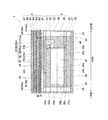
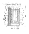
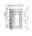
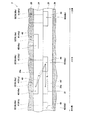
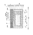
図7及び図8は本発明の第2実施形態に係るインクジェットヘッド101の部分断面図である。図7には、接続流路132のうち、Y方向一方側に配列された第1圧力室列の奇数行目の圧力室33(36a)に接続される第1接続流路138aの縦断面形状が示され、図8には、接続流路132のうち、Y方向一方側に配列された第1圧力室列の偶数行目の圧力室33(36b)に接続される第1接続流路138bの縦断面形状が示されている。本実施形態は、第1実施形態に対し、各第1接続流路138(138a,138b)の第1上流流路140(140a,140b)が相違している。以下、第1実施形態と同一の構成には同一の符号を付して詳細な説明を省略する。
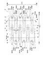
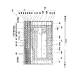
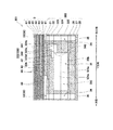
図9は本発明の第3実施形態に係るインクジェットヘッド201の部分断面図である。。図9には、接続流路232のうち、Y方向一方側に配列された第1圧力室列36をなす圧力室33に接続される第1接続流路238の縦断面形状が示されている。本実施形態は、第1実施形態に対し、第1接続流路の第1及び第2接続流路240,241が相違している。以下、第1実施形態と同一の構成には同一の符号を付して詳細な説明を省略する。
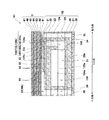
図10は本発明の第4実施形態に係るインクジェットヘッド301の部分断面図である。図10には、接続流路332のうち、Y方向一方側に配列された第1圧力室列36をなす圧力室33に接続される第1接続流路338の縦断面形状が示されている。本実施形態は、第1実施形態に対し、第1接続流路338の第1及び第2上流流路340,341の構成が相違している。以下、第1実施形態と同様の構成については同一の符号を付して詳細な説明を省略する。
30,130,230,330 インク流路
31 共通インク室(共通液室)
32,132,232,332 接続流路
33 圧力室
35 ノズル
36 第1圧力室列
37 第2圧力室列
38,138,238,338 第1接続流路
39 第2接続流路
Claims (5)
- 液体を噴射する複数のノズルの夫々に対応して設けられた複数の圧力室と、
前記複数の圧力室の夫々に共通に分配される液体が供給される共通液室と、
前記共通液室を前記圧力室に連通させて液体を前記圧力室に供給すべく、前記複数の圧力室の夫々に対応して設けられた複数の接続流路と、を有する液体吐出ヘッドであって、
前記共通液室が一方向に延在して設けられ、
前記複数の圧力室が、前記共通液室の前記一方向に直交する方向の一方側と他方側とに分かれて2列配置され、その一方の列をなす前記圧力室と他方の列をなす前記圧力室とが千鳥状に配列され、
前記複数の接続流路が、一方の列をなす前記圧力室に対応する複数の第1接続流路と、他方の列をなす前記圧力室に対応する複数の第2接続流路とを含み、
前記複数の第1接続流路の夫々は、前記一方の列をなす圧力室から平面視で前記他方の列をなす複数の前記圧力室の間を前記直交方向に平行に形成され、前記共通液室の平面視外形線の前記他端側から外側の領域まで延びて前記共通液室と連通し、
前記複数の第2接続流路の夫々は、前記他方の列をなす圧力室から平面視で前記一方の列をなす複数の前記圧力室の間を前記直交方向に平行に形成され、前記共通液室の平面視外形線の前記一端側から外側の領域まで延びて前記共通液室と連通し、
前記複数の第1接続流路と前記複数の第2接続流路とが前記一方向に関して交互に配置され、
前記複数の第1接続流路は夫々、前記共通液室の前記一端側に開口する流入口を有し、
前記第1接続流路の前記流入口は、夫々、隣り合う前記流入口と高さ位置が異なることを特徴とする液体吐出ヘッド。 - 前記第1接続流路の流入口のうち一部の流入口が、前記共通液室の鉛直方向上端部に連通していることを特徴とする請求項1に記載の液体吐出ヘッド。
- 前記複数の第2接続流路は夫々、前記共通液室の前記他端側に開口する流入口を有し、
前記第2接続流路の前記流入口が夫々、隣り合う前記流入口と高さ位置が異なることを特徴とする請求項1又は2に記載の液体吐出ヘッド。 - 前記第2接続流路の流入口のうち一部の流入口が、前記共通液室の鉛直方向上端部に連通していることを特徴とする請求項3に記載の液体吐出ヘッド。
- 前記共通液室を構成するためのマニホールド孔を有するマニホールド層と、
前記圧力室を構成するための圧力室孔を有する圧力室層と、
前記マニホールド層と前記圧力室層との間に介在し、前記接続流路を構成するための孔及び溝を有する接続流路層とを有し、
前記接続流路の上流端部が、前記マニホールド層を構成するプレート部材のうち前記接続流路層が配置される側の面がハーフエッチングされて形成される溝により、構成されており、
前記溝の一端が前記マニホールド孔に繋がり、前記溝の他端が前記接続流路層の前記溝及び孔の一つに連通していることを特徴とする請求項1乃至4のいずれか1項に記載の液体吐出ヘッド。
Priority Applications (2)
| Application Number | Priority Date | Filing Date | Title |
|---|---|---|---|
| JP2008201869A JP4640468B2 (ja) | 2008-08-05 | 2008-08-05 | 液体吐出ヘッド |
| US12/535,189 US8226211B2 (en) | 2008-08-05 | 2009-08-04 | Liquid discharge head and printer |
Applications Claiming Priority (1)
| Application Number | Priority Date | Filing Date | Title |
|---|---|---|---|
| JP2008201869A JP4640468B2 (ja) | 2008-08-05 | 2008-08-05 | 液体吐出ヘッド |
Publications (2)
| Publication Number | Publication Date |
|---|---|
| JP2010036449A JP2010036449A (ja) | 2010-02-18 |
| JP4640468B2 true JP4640468B2 (ja) | 2011-03-02 |
Family
ID=41652519
Family Applications (1)
| Application Number | Title | Priority Date | Filing Date |
|---|---|---|---|
| JP2008201869A Active JP4640468B2 (ja) | 2008-08-05 | 2008-08-05 | 液体吐出ヘッド |
Country Status (2)
| Country | Link |
|---|---|
| US (1) | US8226211B2 (ja) |
| JP (1) | JP4640468B2 (ja) |
Families Citing this family (5)
| Publication number | Priority date | Publication date | Assignee | Title |
|---|---|---|---|---|
| JP7131260B2 (ja) * | 2018-09-28 | 2022-09-06 | ブラザー工業株式会社 | 液体吐出ヘッド |
| JP7318399B2 (ja) * | 2019-07-31 | 2023-08-01 | セイコーエプソン株式会社 | 液体吐出ヘッドおよび液体吐出装置 |
| JP7318398B2 (ja) * | 2019-07-31 | 2023-08-01 | セイコーエプソン株式会社 | 液体吐出ヘッドおよび液体吐出装置 |
| US11104128B2 (en) | 2018-12-21 | 2021-08-31 | Seiko Epson Corporation | Liquid ejecting head and liquid ejecting system |
| JP7439482B2 (ja) * | 2019-12-03 | 2024-02-28 | セイコーエプソン株式会社 | 液体噴射ヘッドおよび液体噴射システム |
Family Cites Families (7)
| Publication number | Priority date | Publication date | Assignee | Title |
|---|---|---|---|---|
| JP4296751B2 (ja) | 2002-05-07 | 2009-07-15 | ブラザー工業株式会社 | インクジェットヘッド |
| JP4622362B2 (ja) * | 2004-07-26 | 2011-02-02 | ブラザー工業株式会社 | インクジェットヘッド |
| JP4274084B2 (ja) * | 2004-08-27 | 2009-06-03 | ブラザー工業株式会社 | インクジェットヘッド |
| JP4605363B2 (ja) * | 2004-11-11 | 2011-01-05 | ブラザー工業株式会社 | インクジェットヘッドの製造方法 |
| JP4810908B2 (ja) * | 2005-07-25 | 2011-11-09 | ブラザー工業株式会社 | インクジェットヘッド |
| JP2008037099A (ja) * | 2006-07-14 | 2008-02-21 | Brother Ind Ltd | 液体移送装置及びインクジェットヘッド |
| US7806521B2 (en) * | 2006-08-01 | 2010-10-05 | Brother Kogyo Kabushiki Kaisha | Liquid transport apparatus and method for producing liquid transport apparatus |
-
2008
- 2008-08-05 JP JP2008201869A patent/JP4640468B2/ja active Active
-
2009
- 2009-08-04 US US12/535,189 patent/US8226211B2/en active Active
Also Published As
| Publication number | Publication date |
|---|---|
| US8226211B2 (en) | 2012-07-24 |
| US20100033537A1 (en) | 2010-02-11 |
| JP2010036449A (ja) | 2010-02-18 |
Similar Documents
| Publication | Publication Date | Title |
|---|---|---|
| JP3918928B2 (ja) | インクジェットプリンタヘッド | |
| JP5035486B2 (ja) | 液体移送装置及びインクジェットヘッド | |
| JP4640468B2 (ja) | 液体吐出ヘッド | |
| KR20160026709A (ko) | 액체 토출 헤드 및 이것을 사용한 헤드 유닛 | |
| JP6278588B2 (ja) | 液体噴射ヘッドおよび液体噴射装置 | |
| JP4941038B2 (ja) | 液滴吐出装置 | |
| JP4224822B2 (ja) | インクジェットプリンタヘッド | |
| JP7404812B2 (ja) | 液体噴射ヘッド | |
| JP4507170B2 (ja) | インクジェットプリンタヘッド | |
| JP2009160798A (ja) | 液滴吐出ヘッド | |
| JP2008200951A (ja) | 流路形成体 | |
| JP2009241318A (ja) | 液滴噴射ヘッド及びその製造方法 | |
| US7896478B2 (en) | Fluid path unit for fluid ejection device | |
| US7794062B2 (en) | Liquid droplet ejecting device | |
| JP2007268867A (ja) | インクジェットヘッド | |
| JP5598380B2 (ja) | 液体吐出装置 | |
| JP4950628B2 (ja) | 液体吐出ヘッド | |
| JP4475153B2 (ja) | インクジェットヘッド | |
| JP6314264B2 (ja) | 液体噴射ヘッドおよび液体噴射装置 | |
| JP4367049B2 (ja) | インクジェットヘッド | |
| JP2009083243A (ja) | 液滴吐出ヘッド用のキャビティユニット | |
| JP6582725B2 (ja) | 液体吐出装置 | |
| JP2008037099A (ja) | 液体移送装置及びインクジェットヘッド | |
| US7597427B2 (en) | Liquid channel structure and liquid-droplet jetting apparatus | |
| JP4962352B2 (ja) | 液滴吐出ヘッド |
Legal Events
| Date | Code | Title | Description |
|---|---|---|---|
| A621 | Written request for application examination |
Free format text: JAPANESE INTERMEDIATE CODE: A621 Effective date: 20100305 |
|
| A977 | Report on retrieval |
Free format text: JAPANESE INTERMEDIATE CODE: A971007 Effective date: 20100805 |
|
| A131 | Notification of reasons for refusal |
Free format text: JAPANESE INTERMEDIATE CODE: A131 Effective date: 20100817 |
|
| A521 | Request for written amendment filed |
Free format text: JAPANESE INTERMEDIATE CODE: A523 Effective date: 20101015 |
|
| TRDD | Decision of grant or rejection written | ||
| A01 | Written decision to grant a patent or to grant a registration (utility model) |
Free format text: JAPANESE INTERMEDIATE CODE: A01 Effective date: 20101102 |
|
| A01 | Written decision to grant a patent or to grant a registration (utility model) |
Free format text: JAPANESE INTERMEDIATE CODE: A01 |
|
| A61 | First payment of annual fees (during grant procedure) |
Free format text: JAPANESE INTERMEDIATE CODE: A61 Effective date: 20101115 |
|
| R150 | Certificate of patent or registration of utility model |
Ref document number: 4640468 Country of ref document: JP Free format text: JAPANESE INTERMEDIATE CODE: R150 Free format text: JAPANESE INTERMEDIATE CODE: R150 |
|
| FPAY | Renewal fee payment (event date is renewal date of database) |
Free format text: PAYMENT UNTIL: 20131210 Year of fee payment: 3 |