JP4584755B2 - Pressure roller for attaching polishing pad in double-side polishing apparatus, and method for attaching polishing pad with pressure roller - Google Patents
Pressure roller for attaching polishing pad in double-side polishing apparatus, and method for attaching polishing pad with pressure roller Download PDFInfo
- Publication number
- JP4584755B2 JP4584755B2 JP2005109990A JP2005109990A JP4584755B2 JP 4584755 B2 JP4584755 B2 JP 4584755B2 JP 2005109990 A JP2005109990 A JP 2005109990A JP 2005109990 A JP2005109990 A JP 2005109990A JP 4584755 B2 JP4584755 B2 JP 4584755B2
- Authority
- JP
- Japan
- Prior art keywords
- surface plate
- pad
- roller
- polishing pad
- polishing
- Prior art date
- Legal status (The legal status is an assumption and is not a legal conclusion. Google has not performed a legal analysis and makes no representation as to the accuracy of the status listed.)
- Active
Links
Images


Description
本発明は、両面研磨装置における上下の定盤に研磨パッドを貼着するのに用いられる研磨パッド貼着用加圧ローラと、この加圧ローラを使用して定盤に研磨パッドを貼着するための方法とに関するものである。 The present invention is to apply a polishing pad sticking pressure roller used to stick a polishing pad to upper and lower surface plates in a double-side polishing apparatus, and to attach the polishing pad to a surface plate using this pressure roller. It is related to the method.
半導体ウエハや、フォトマスク等に用いられるガラスウエハあるいはセラミックスウエハといったような、薄板状をしたワークの表裏両面を研磨加工する場合、ラッピング装置やポリッシング装置等の両面研磨装置が使用される。この両面研磨装置は、一般に、円環形をしたパッド貼着面に研磨パッドを貼着した上下の定盤と、下定盤の中央に位置するサンギアと、該下定盤の外周を取り囲むように位置するインターナルギアと、上記下定盤上に位置してこれら両ギアに噛合する複数のキャリヤとを有し、各キャリヤのワーク保持孔内にワークを嵌合、保持させ、上記サンギアを回転させるか又はサンギアとインターナルギアの両方を回転させて各キャリヤをサンギアの回りで自転及び公転させると共に、研磨液を供給しながら、回転する上下の定盤の上記研磨パッドで上記ワークの表裏面を研磨加工するものである。 When polishing both the front and back surfaces of a thin workpiece such as a semiconductor wafer, a glass wafer used for a photomask, or a ceramic wafer, a double-side polishing apparatus such as a lapping apparatus or a polishing apparatus is used. This double-side polishing apparatus is generally positioned so as to surround the outer periphery of the lower surface plate, the upper and lower surface plates with the polishing pad attached to the annular pad attaching surface, the sun gear located in the center of the lower surface plate An internal gear and a plurality of carriers that are positioned on the lower surface plate and mesh with the two gears. The work is fitted and held in the work holding holes of each carrier, and the sun gear is rotated or the sun gear is rotated. And both the internal gear and the internal gear are rotated and revolved around the sun gear, and the front and back surfaces of the workpiece are polished with the polishing pads on the rotating upper and lower surface plates while supplying the polishing liquid. It is.
この種の両面研磨装置においては、加工と共に上記研磨パッドが徐々に摩耗又は変形していくため、研磨精度が低下する前の適切な時期に摩耗又は変形した研磨パッドを新しいものと交換する必要がある。その交換作業は、摩耗又は変形した古い研磨パッドを定盤から剥がし、新しい研磨パッドを両面接着シートで貼着することにより行われるが、その貼着作業には、例えば特許文献1に従来技術として記載されているように、加圧ローラを使用するのが一般的である。その方法は、定盤に仮接着した研磨パッドの上に上記加圧ローラを押し付けて転動させることにより、この加圧ローラでパッド全体を加圧して定盤に圧着させるもので、それらの作業は全て手作業で行われている。 In this type of double-side polishing apparatus, since the polishing pad is gradually worn or deformed with processing, it is necessary to replace the worn or deformed polishing pad with a new one at an appropriate time before the polishing accuracy decreases. is there. The replacement work is performed by peeling off the worn or deformed old polishing pad from the surface plate, and sticking the new polishing pad with a double-sided adhesive sheet. As described, it is common to use a pressure roller. The method is to press the pressure roller onto the polishing pad temporarily bonded to the surface plate and roll it, and press the entire pad with this pressure roller to press it against the surface plate. Are all done manually.
ところが、定盤及び研磨パッドの径が小さい場合はそれほど問題ないが、両面研磨装置のように定盤及び研磨パッドの径が大きくなると、上記加圧ローラを手作業でパッド全体に均等に押し付けるのは非常に難しく、研磨パッドが位置ずれして皺を生じたり、接着むらが発生したり、研磨パッドと定盤との間に空気が封じ込められて該研磨パッドに凹凸が形成され易いといったような問題があった。 However, there is no problem when the diameter of the surface plate and the polishing pad is small. However, when the diameter of the surface plate and the polishing pad is increased as in the double-side polishing apparatus, the pressure roller is pressed evenly over the entire pad manually. Is very difficult, the polishing pad is misaligned to cause wrinkles, uneven adhesion occurs, air is trapped between the polishing pad and the surface plate, and irregularities are easily formed on the polishing pad. There was a problem.
特に、上定盤の場合には、その下面のパッド貼着面に研磨パッドを上向きに貼着しなければならないため、難しい作業姿勢を取らざるを得ず、貼着作業が一段と困難である。このため、該上定盤を一旦取り外して研磨パッドを貼着する方法が用いられているが、パッド貼着作業の他に、該上定盤を装置に着脱する作業も必要になるため、この上定盤に対する作業だけで1〜4時間もの作業時間を要することとなり、研磨を長時間中断しなければならなかった。 In particular, in the case of an upper surface plate, the polishing pad must be attached upward on the pad attachment surface on the lower surface thereof, so a difficult working posture must be taken, and the attaching operation is further difficult. For this reason, a method of once removing the upper surface plate and pasting the polishing pad is used, but in addition to the pad pasting work, it is also necessary to attach and detach the upper surface plate to the apparatus. The work for the upper surface plate alone requires 1 to 4 hours of work, and polishing must be interrupted for a long time.
そこで、研磨パッドを機械的に加圧して貼着することができる技術も色々提案されている。例えば、特許文献2には、上定盤の下面に下定盤を利用して研磨パッドを機械的に加圧して貼着する方法が開示されている。この方法は、研磨パッドを載置したガイド部材を上下の定盤間に介在させ、両定盤を近接させることにより、下定盤で上記ガイド部材を押圧して研磨パッドを上定盤の下面に貼着するものである。
Accordingly, various techniques have been proposed that allow the polishing pad to be mechanically pressurized and attached. For example,
また、特許文献3には、加圧ローラで研磨パッドを定盤に機械的に押し付ける技術が提案されている。この技術は、プレッシャプレートでワークを定盤(ベースプレート)に押し付けてその片面を研磨する片面研磨装置を対象とするもので、上記プレッシャプレートの下面に加圧ローラを取り付け、このプレッシャプレートで加圧ローラを研磨パッドに押し付けることにより、該研磨パッドを定盤に圧着させるものである。
この方法は、手作業の場合よりは少ない労力で済むうえに、短時間のうちに研磨パッド全体を均一に加圧することができるため、非常に簡単かつ効率的である。
This method is very simple and efficient because it requires less labor than manual work and can uniformly pressurize the entire polishing pad in a short time.
しかしながら、上記特許文献2に記載の技術は、研磨パッドを加圧部材を介して面で加圧するため、加圧にばらつきが発生し易いだけでなく、気泡が逃げずに研磨パッドと定盤との間に封じ込められ易いという欠点がある。
However, since the technique described in
また、特許文献3に記載の技術は、1つの定盤だけを有する片面研磨装置が対象であって、上下2つの定盤を有する両面研磨装置とは装置の構成が基本的に相違するため、この技術を両面研磨装置にそのまま転用することはできない。即ち、上記片面研磨装置の技術を両面研磨装置に転用する場合には、上記プレッシャプレートに相当する加圧用部材を新たに設け、これに加圧ローラを保持させる必要があるが、それに付随して流体圧シリンダや圧力制御系等も増設しなければならず、しかも、下定盤と上定盤の両方に対して加圧ローラを押し付けられるようにしなければならないため、研磨装置の構造が複雑化し、実用的とはいえない。特に、このような加圧用部材を上下の定盤間に設置し、その加圧ローラで上定盤の下面に研磨パッドを上向きに押し付けて貼着するように構成するのは、容易ではない。さらに、複数の加圧用部材を設けるようにすると、相互間の加圧力を均等にするための調圧機構を更に付設する必要が生じ、構造が一層複雑化する。また、加圧用部材を直接加圧ローラに押し当てると、該加圧用部材との摩擦によって加圧ローラが回転しにくくなるおそれがある。
Further, the technique described in
そこで本発明の目的は、両面研磨装置における上下の定盤に加圧ローラを用いて研磨パッドを機械的に貼着することができる、構成が簡単で操作も容易なパッド貼着のための新たな技術手段を提供することにある。 Accordingly, an object of the present invention is to provide a new pad attachment that can be mechanically attached to the upper and lower surface plates of the double-side polishing apparatus using pressure rollers, and that is simple in configuration and easy to operate. Is to provide technical means.
上記課題を解決するため、本発明によれば、キャリヤに保持されたワークを両側から挟んで研磨する上定盤及び下定盤と、上記キャリヤを駆動するためのサンギヤ及びインターナルギヤとを備えた両面研磨装置において用いられ、上記上定盤及び/又は下定盤の円環状をしたパッド貼着面に円環状の研磨パッドを貼着するための加圧ローラであって、該加圧ローラが、上記パッド貼着面の幅と同等以上の長さを有する円柱形のローラ本体と、該ローラ本体を回転自在に支持するローラ軸と、該ローラ軸の両端にそれぞれ形成された係止部とを有していて、これらの係止部が、上記ローラ軸の両端に個別に取り付けられた互いに独立するブロック形の部材により、上記研磨装置における下定盤の内外周側に設けられた係止受部にそれぞれ係止可能なるように形成され、これらの係止部を上記係止受部に係止させることにより、該研磨装置に対し、上記ローラ本体が定盤の半径方向に位置して研磨パッドに全幅にわたり当接するように取付可能であることを特徴とする両面研磨装置における研磨パッド貼着用加圧ローラが提供される。 In order to solve the above problems, according to the present invention, an upper surface plate and a lower surface plate that sandwich and hold a work held by a carrier from both sides, and a sun gear and an internal gear for driving the carrier are provided. A pressure roller used in a double-side polishing apparatus, for attaching an annular polishing pad to the annular pad attachment surface of the upper surface plate and / or the lower surface plate, the pressure roller comprising: A cylindrical roller body having a length equal to or greater than the width of the pad adhering surface, a roller shaft that rotatably supports the roller body, and a locking portion formed at each end of the roller shaft. The latch receiving portions provided on the inner and outer peripheral sides of the lower surface plate in the polishing apparatus by means of independent block-shaped members individually attached to both ends of the roller shaft. Each can be locked It is formed so that, by these locking portion to be locked in the locking receiving portion, with respect to the polishing apparatus, the roller body abuts over the entire width in the polishing pad is located in the radial direction of the platen Thus, a pressure roller for attaching a polishing pad in a double-side polishing apparatus is provided.
また、本発明によれば、キャリヤに保持されたワークを両側から挟んで研磨する上定盤及び下定盤と、上記キャリヤを駆動するためのサンギヤ及びインターナルギヤと、上定盤及び/又は下定盤の円環状をしたパッド貼着面に円環状の研磨パッドを貼着するための加圧ローラとを有し、上記加圧ローラは、上記パッド貼着面の幅と同等以上の長さを有する円柱形のローラ本体と、該ローラ本体を回転自在に支持するローラ軸と、該ローラ軸の両端にそれぞれ形成された係止部とを有していて、これらの係止部が、上記ローラ軸の両端に個別に取り付けられた互いに独立するブロック形の部材により、上記下定盤の内外周側に設けられた係止受部にそれぞれ係止可能なるように形成され、上記上定盤及び/又は下定盤のパッド貼着面に研磨パッドを仮接着したあと、上記加圧ローラを上下の定盤間に半径方向に介在させてローラ本体を研磨パッドに全幅にわたり当接させると共に、ローラ軸の両端の係止部を下定盤の内外周側の係止受部にそれぞれ係止させ、上定盤で荷重を加えた状態にして上下の定盤を互いに逆向きに回転させることにより、上記ローラ本体を定盤の回転に追随させて従動回転させながら、該ローラ本体によって上記研磨パッドをパッド貼着面に圧着させるように構成されていることを特徴とする両面研磨装置が提供される。Further, according to the present invention, the upper surface plate and the lower surface plate that sandwich and hold the work held by the carrier from both sides, the sun gear and the internal gear for driving the carrier, the upper surface plate and / or the lower surface plate. A pressure roller for adhering an annular polishing pad to an annular pad adhering surface of the board, and the pressure roller has a length equal to or greater than the width of the pad adhering surface. A cylindrical roller body having a roller shaft, a roller shaft that rotatably supports the roller body, and locking portions respectively formed at both ends of the roller shaft. The independent block-shaped members individually attached to both ends of the shaft are formed so as to be able to be respectively locked to locking receiving portions provided on the inner and outer peripheral sides of the lower surface plate, and the upper surface plate and / or Alternatively, use a polishing pad on the pad attachment surface of the lower surface plate. After the temporary bonding, the pressure roller is interposed between the upper and lower surface plates in the radial direction so that the roller body is in contact with the polishing pad over the entire width, and the engaging portions at both ends of the roller shaft are connected to the inner and outer circumferences of the lower surface plate. The roller body follows the rotation of the surface plate by following the rotation of the surface plate by rotating the upper surface plate and the upper surface plate in opposite directions with the load being applied to the lock receiving portion on the side. A double-side polishing apparatus is provided, wherein the polishing pad is pressed against the pad attachment surface by the roller body while rotating.
更に、本発明によれば、キャリヤに保持されたワークを両側から挟んで研磨する上定盤及び下定盤と、上記キャリヤを駆動するためのサンギヤ及びインターナルギヤとを備えた両面研磨装置において、上記上定盤及び/又は下定盤の円環状をしたパッド貼着面に円環状の研磨パッドを貼着するための方法であって、上記パッド貼着面の幅と同等以上の長さを有する円柱形のローラ本体と、該ローラ本体を回転自在に支持するローラ軸と、該ローラ軸の両端にそれぞれ形成された係止部とを有し、これらの係止部が上記ローラ軸の両端に個別に取り付けられた互いに独立するブロック形の部材により形成されていて、上記研磨装置に対して着脱自在である複数の加圧ローラを使用し、上記上定盤及び/又は下定盤のパッド貼着面に研磨パッドを仮接着したあと、上記加圧ローラを上下の定盤間に半径方向に介在させてローラ本体を研磨パッドに全幅にわたり当接させると共に、上記ローラ軸の両端の係止部を下定盤の内外周側に設けられた係止受部にそれぞれ係止させ、上定盤で荷重を加えた状態にして上下の定盤を互いに逆向きに回転させることにより、上記ローラ本体を定盤の回転に追随させて従動回転させながら、該ローラ本体によって上記研磨パッドをパッド貼着面に圧着させることを特徴とする両面研磨装置における研磨パッドの貼着方法が提供される。 Furthermore, according to the present invention, in a double-side polishing apparatus comprising an upper surface plate and a lower surface plate for sandwiching a work held by a carrier from both sides, and a sun gear and an internal gear for driving the carrier, A method for adhering an annular polishing pad to an annular pad adhering surface of the upper surface plate and / or lower surface plate, having a length equal to or greater than the width of the pad adhering surface. It has a cylindrical roller body, a roller shaft that rotatably supports the roller body, and locking portions formed at both ends of the roller shaft. These locking portions are at both ends of the roller shaft. Using a plurality of pressure rollers which are formed by individually attached block-shaped members and are detachable from the polishing apparatus, the upper surface plate and / or the lower surface plate are attached to the pad. Polishing pad on the surface After bonding, dissipate contact over the entire width of the roller body is interposed radially polishing pad between the platen up and down the pressure roller, the inner and outer peripheral side of the lower surface plate locking portions at both ends of the roller shaft each engagement was locked to the locking receiving portion provided on, by rotating the platen up and down in the state in which the load is applied on the surface plate in opposite directions, to follow the roller body to the rotation of the platen Thus, a polishing pad attaching method in a double-side polishing apparatus is provided in which the polishing pad is pressure-bonded to the pad attaching surface by the roller body while being driven to rotate.
本発明によれば、複数の加圧ローラを上下の定盤間に介在させ、両側から荷重を加えた状態で両定盤を互いに逆向きに回転させるだけの非常に簡単な構成及び操作により、各加圧ローラで研磨パッドを機械的に押圧して定盤に圧着させることができる。
この場合、上下の定盤を逆向きに回転させて上記加圧ローラを従動回転させることにより、該加圧ローラが上下何れの定盤の研磨パッドとも擦れ合わないようにして、該研磨パッドの損傷や摩耗あるいは目潰れ等を生じるのを防止することができる。
しかも、上下の定盤によって加圧ローラ全体が同時にかつ均等に加圧されるため、この加圧ローラによる加圧力が研磨パッド全体に均等に作用することになり、このため接着むらが発生せず、研磨パッド全体を定盤に対して均一に貼着することができる。
According to the present invention, a plurality of pressure rollers are interposed between the upper and lower surface plates, and with a very simple configuration and operation in which both surface plates are rotated in opposite directions with a load applied from both sides, The polishing pad can be mechanically pressed by each pressure roller to be pressure-bonded to the surface plate.
In this case, the upper and lower surface plates are rotated in the opposite directions and the pressure roller is driven to rotate so that the pressure roller does not rub against the polishing pad of any of the upper and lower surface plates. It is possible to prevent the occurrence of damage, wear or clogging.
Moreover, since the entire pressure roller is simultaneously and evenly pressed by the upper and lower surface plates, the pressure applied by the pressure roller acts evenly on the entire polishing pad, so that uneven adhesion does not occur. The entire polishing pad can be uniformly adhered to the surface plate.
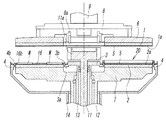
図1は両面研磨装置の要部の断面を概略的に示すもので、この両面研磨装置は、半導体ウエハや、フォトマスク等に用いられるガラスウエハあるいはセラミックスウエハといったような、薄板状をしたワークの表裏両面を研磨加工するためのもので、ラッピング装置やポリッシング装置等によって代表されるものである。 FIG. 1 schematically shows a cross section of a main part of a double-side polishing apparatus. This double-side polishing apparatus is used for a thin plate-like workpiece such as a semiconductor wafer, a glass wafer used for a photomask, or a ceramic wafer. It is for polishing both the front and back surfaces, and is represented by a lapping device or a polishing device.
上記両面研磨装置は、図2及び図3からも分かるように、同軸上に位置する円環形の上下の定盤1,2と、下定盤2の中央に位置するサンギヤ3と、該下定盤2の外周を取り囲むように位置するインターナルギヤ4とを有していて、上記両定盤1,2と、両ギヤ3,4のうち少なくともサンギヤ3とが、それぞれ駆動軸11,12,13,14を介して図示しないモーターに連結され、必要な方向に必要な速度で個別に回転駆動されるようになっている。
As can be seen from FIGS. 2 and 3, the double-side polishing apparatus includes annular upper and
上記上下の定盤1,2は、それぞれ定盤受け6,7に取り付けられることにより、着脱自在となっている。このうち上定盤1は、上記定盤受け6及び定盤吊り8を介して昇降用シリンダのロッド9に取り付けられ、この昇降用シリンダで昇降自在となっており、ワークの研磨時や後述する研磨パッドの交換時等に該上定盤1が下降すると、上記定盤吊り8に取り付けられたフック8aが駆動軸11の上端のドライバ11aに係合し、このドライバ11aを介して回転駆動されるようになっている。
The upper and
上記上定盤1及び下定盤2は、その下面又は上面に円環形をしたパッド貼着面1a及び2aを有し、これらのパッド貼着面1a,2aにそれぞれ、全体としてほぼ均一厚さを有する円環形の研磨パッド5が、該研磨パッド5の裏面全体に接着された両面接着シートを介して貼着されている。上記両定盤1,2におけるパッド貼着面1a,2aの内外径の寸法は互いに同じであり、従って、両定盤1,2に貼着される研磨パッド5,5の内外径の寸法も互いに同じである。なお、上記研磨パッド5としては、例えば硬質ウレタン製あるいは硬質不織布製のものを使用することができる。
The
また、上記サンギヤ3及びインターナルギヤ4は、リング状をした基体3a,4aの外周又は内周に、歯を構成する多数のピン3b,4bを、必要なピッチで鉛直かつ円環状に配設したもので、ピン歯車の形態を有するものである。
Further, the
上記両面研磨装置によるワークの研磨時には、図1の左半部と図2に一つのキャリヤで代表して示すように、外周に歯16aを備えた複数のキャリヤ16が、上記下定盤2上にほぼ等間隔に配置されると共に、上記両ギヤ3,4に噛合せしめられる。そして、各キャリヤ16に形成されている複数のワーク保持孔16b内にそれぞれ円板形のワークWを嵌合、保持させ、上記サンギヤ3を回転させるか又はサンギヤ3とインターナルギヤ4の両方を回転させることにより、上記各キャリヤ16をサンギヤ3の回りで自転及び公転させながら、上下両定盤1,2の間に研磨液を供給し、回転するこれらの定盤1,2の研磨パッド5,5で上記ワークWの表裏面を研磨加工する。
When the workpiece is polished by the double-side polishing apparatus, a plurality of
上記両面研磨装置においては、上記定盤1,2に研磨パッド5を貼着する際に、複数の加圧ローラ20が使用される。この加圧ローラ20は、研磨装置に対して個別に着脱自在のもので、図3及び図4からも明らかなように、金属(好ましくは錆びにくいステンレスやその他の非鉄金属)からなる円柱形のローラ本体21と、このローラ本体21を軸線の回りに回転自在に支持するローラ軸22と、このローラ軸22の両端に設けられた係止部23a,23bとを有し、これらの係止部23a,23bを、研磨装置における下定盤2の内外周側に形成された係止受部24a,24bに係止させることにより、該研磨装置に取り付けられるものである。上記ローラ本体21の外周面には、フッ素樹脂をコーティングしておくことが望ましい。
In the double-side polishing apparatus, a plurality of
上記ローラ本体21の長さは、上下の定盤1,2における円環形のパッド貼着面1a,2aの幅(従って研磨パッド5の幅)と同じかそれより僅かに大きく形成されている。また、上記係止部23a,23bは、ブロック形の部材の下面に1つ又は複数の係止孔25を備えた構成を有していて、この係止孔25を上記サンギヤ3及びインターナルギヤ4の1つ又は複数のピン3b,4bに係合させるように構成されている。従って、研磨装置側の上記係止受部24a,24bは、上記サンギヤ3及びインターナルギヤ4の歯を構成する上記ピン3b,4bで形成されていることになる。
The length of the
上記加圧ローラ20を使用して上下の定盤1,2に研磨パッド5を貼着する場合の操作は、次の通りである。ここでは、上下の定盤1,2に同時に研磨パッド5を貼着する場合について説明されているが、何れか一方の定盤1又は2だけに研磨パッドを貼着する場合の操作も同じである。
The operation when the
先ず、上定盤1を図1及び図3に示すように作業の邪魔にならない位置まで上昇させ、両定盤1,2に古い研磨パッドが貼着されている場合には、そのパッドを剥がし、新しい研磨パッド5,5を両面接着シートにより仮接着する。
First, as shown in FIGS. 1 and 3, the
新たな研磨パッド5,5の仮接着が終わると、複数の加圧ローラ20を下定盤2上に設置する。その設置は、各加圧ローラ20の軸線を下定盤2の半径方向に向け、両端の係止部23a,23bに形成された係止孔25を上記サンギヤ3及びインターナルギヤ4のピン3b,4bに係合させることにより行う。このとき使用する加圧ローラ20の数は、2本でも良いが、好ましくは3本以上であり、3本以上の加圧ローラ20を、下定盤2の中心軸線Lの回りに実質的に等しい中心角で放射状に配設することが望ましい。しかし、このように3本以上の加圧ローラ20を使用する場合、それらの中心角が若干異なっていても特に問題はない。
これにより上記各加圧ローラ20は、そのローラ本体21が円環状の研磨パッド5を下定盤2の半径方向に横断すると共に、該研磨パッド5の幅全体に当接するように配設される。
When the temporary bonding of the
Accordingly, each of the
図3において、符号26,27は、下定盤2上にセットされた加圧ローラ20の必要以上の沈み込みを制限するためのストッパであって、サンギヤ3及びインターナルギヤ4に設けられており、上記加圧ローラ20の両端の係止部23a,23bが当接することによって該加圧ローラ20がそれ以上沈み込まないようにするものである。
In FIG. 3,
次に、図5に示すように、上昇位置にある上定盤1を研磨パッド5が各加圧ローラ20のローラ本体21に当接する位置まで下降させ、上下の定盤1,2により該ローラ本体21を挟持して上定盤1で必要な荷重(加圧力)を加える。このときの荷重は、研磨装置の規模や研磨パッド5の種類等によって最適値は異なるが、一般的には3〜20kg/cm2 程度であることが望ましい。かくして上下の定盤1,2間に加圧ローラ20を介在させてローラ本体21に荷重を加えることにより、該ローラ本体21で両定盤1,2の研磨パッド5,5が、上記荷重に対応する加圧力でパッド貼着面1a,2aに押し付けられることになる。
Next, as shown in FIG. 5, the
そして、上記サンギヤ3とインターナルギヤ4とを非回転の状態に固定し、上下の定盤1,2だけをゆっくりした速度で互いに逆方向に等速で回転させる。これにより、各加圧ローラ20のローラ本体21は、一定の位置において、回転する両定盤1,2に追随してローラ軸22の回りを従動回転し、これら両定盤1,2と一緒に回転する研磨パッド5,5を加圧してパッド貼着面1a,2aに圧着させる。
上記研磨パッド5,5の貼着が終わると、上定盤1を上昇させ、各加圧ローラ20を取り外して必要な場所に収納する。
Then, the
When the
かくして、複数の加圧ローラ20を上下の定盤1,2間に介在させ、荷重を加えた状態で両定盤1,2を互いに逆向きに回転させるだけの非常に簡単でしかも合理的な構成及び操作により、各加圧ローラ20のローラ本体21で上下両定盤1,2に仮接着された研磨パッド5,5に機械的に加圧し、パッド貼着面1a,2aに圧着することができる。この場合、上下の定盤1,2を逆向きに回転させることでローラ本体21を従動回転させるようにしているから、該ローラ本体21が上下何れの定盤1,2の研磨パッド5,5とも擦れ合うことがなく、該研磨パッド5,5の損傷や摩耗あるいは目潰れ等を生じることがない。しかも、上下の定盤1,2によってローラ本体21全体が同時にかつ均等に加圧されるため、このローラ本体21による加圧力が研磨パッド5,5全体に均等に作用することになり、このため接着むらが発生せず、研磨パッド5,5全体を定盤1,2に対して均一に貼着することができる。
In this way, a plurality of
上記実施形態では、加圧ローラ20の両端の係止部23a,23bが係止孔25を有していて、この係止孔25をサンギヤ3及びインターナルギヤ4の係止受部24a,24bを兼ねるピン3b,4bに係合させるようになっているが、これらの係止部23a,23b及び係止受部24a,24bの構成はこのようなものに限定されない。例えば、上記係止受部24a,24bをピン3b,4bに兼用させることなく、ピン以外の場所に上記係止部23a,23bの係止孔25に嵌合するピンや突起などの専用の凸部を形成しても良い。あるいは、係止部23a,23b側を凸部とし、係止受部24a,24b側を孔などの凹部としてそれらを係合させるようにしても良い。
In the above embodiment, the locking
なお、上記実施形態においては、サンギヤ3及びインターナルギヤ4がピン歯車としての形態を有していて、多数のピン3b,4bによって歯が形成されているが、通常の平歯車のように、内外周に中心軸線と平行する直線歯を放射状に備えたものであっても良い。このようにサンギヤ3及びインターナルギヤ4が直線歯を備えたものである場合、上記加圧ローラ20における係止部23a,23bを、上記直線歯と同様の歯状の凹凸を有するように形成し、この凹凸をサンギヤ3又はインターナルギヤ4の直線歯に噛合させるように構成することもできる。
In the above embodiment, the
1 上定盤
2 下定盤
1a,2a パッド貼着面
3 サンギヤ
4 インターナルギヤ
5 研磨パッド
16 キャリヤ
20 加圧ローラ
21 ローラ本体
22 ローラ軸
23a,23b 係止部
24a,24b 係止受部
W ワーク
DESCRIPTION OF
Claims (3)
該加圧ローラが、上記パッド貼着面の幅と同等以上の長さを有する円柱形のローラ本体と、該ローラ本体を回転自在に支持するローラ軸と、該ローラ軸の両端にそれぞれ形成された係止部とを有していて、これらの係止部が、上記ローラ軸の両端に個別に取り付けられた互いに独立するブロック形の部材により、上記研磨装置における下定盤の内外周側に設けられた係止受部にそれぞれ係止可能なるように形成され、これらの係止部を上記係止受部に係止させることにより、該研磨装置に対し、上記ローラ本体が定盤の半径方向に位置して研磨パッドに全幅にわたり当接するように取付可能であることを特徴とする両面研磨装置における研磨パッド貼着用加圧ローラ。 Used in a double-side polishing apparatus comprising an upper surface plate and a lower surface plate that sandwich and hold a work held by a carrier from both sides, and a sun gear and an internal gear for driving the carrier. Or a pressure roller for adhering an annular polishing pad to the annular pad adhering surface of the lower surface plate,
The pressure roller is formed on a cylindrical roller body having a length equal to or greater than the width of the pad attaching surface, a roller shaft that rotatably supports the roller body, and both ends of the roller shaft. These locking portions are provided on the inner and outer peripheral sides of the lower surface plate in the polishing apparatus by independent block-shaped members individually attached to both ends of the roller shaft. It was being respectively formed so as lockable become lock receiving portion, by these locking portion to be locked in the locking receiving portion, with respect to the polishing apparatus, the radial direction of the roller body plate A pressure roller for adhering a polishing pad in a double-side polishing apparatus, wherein the pressure roller can be mounted so as to be in contact with the entire width of the polishing pad.
上記加圧ローラは、上記パッド貼着面の幅と同等以上の長さを有する円柱形のローラ本体と、該ローラ本体を回転自在に支持するローラ軸と、該ローラ軸の両端にそれぞれ形成された係止部とを有していて、これらの係止部が、上記ローラ軸の両端に個別に取り付けられた互いに独立するブロック形の部材により、上記下定盤の内外周側に設けられた係止受部にそれぞれ係止可能なるように形成され、The pressure roller is formed on a cylindrical roller body having a length equal to or greater than the width of the pad attaching surface, a roller shaft that rotatably supports the roller body, and both ends of the roller shaft. Engaging portions provided on the inner and outer peripheral sides of the lower surface plate by independent block-shaped members individually attached to both ends of the roller shaft. It is formed so that it can be locked to the stopper part,
上記上定盤及び/又は下定盤のパッド貼着面に研磨パッドを仮接着したあと、上記加圧ローラを上下の定盤間に半径方向に介在させてローラ本体を研磨パッドに全幅にわたり当接させると共に、ローラ軸の両端の係止部を下定盤の内外周側の係止受部にそれぞれ係止させ、上定盤で荷重を加えた状態にして上下の定盤を互いに逆向きに回転させることにより、上記ローラ本体を定盤の回転に追随させて従動回転させながら、該ローラ本体によって上記研磨パッドをパッド貼着面に圧着させるように構成されていることを特徴とする両面研磨装置。After temporarily bonding the polishing pad to the pad attachment surface of the upper and / or lower surface plate, the pressure roller is interposed between the upper and lower surface plates in the radial direction so that the roller body contacts the polishing pad over the entire width. At the same time, the locking parts at both ends of the roller shaft are locked to the locking receiving parts on the inner and outer circumferences of the lower surface plate, and the upper and lower surface plates are rotated in opposite directions with a load applied on the upper surface plate. By making the roller body follow the rotation of the surface plate, the double-side polishing apparatus is configured to pressure-bond the polishing pad to the pad adhering surface by the roller body while being driven to rotate. .
上記パッド貼着面の幅と同等以上の長さを有する円柱形のローラ本体と、該ローラ本体を回転自在に支持するローラ軸と、該ローラ軸の両端にそれぞれ形成された係止部とを有し、これらの係止部が上記ローラ軸の両端に個別に取り付けられた互いに独立するブロック形の部材により形成されていて、上記研磨装置に対して着脱自在である複数の加圧ローラを使用し、
上記上定盤及び/又は下定盤のパッド貼着面に研磨パッドを仮接着したあと、上記加圧ローラを上下の定盤間に半径方向に介在させてローラ本体を研磨パッドに全幅にわたり当接させると共に、上記ローラ軸の両端の係止部を下定盤の内外周側に設けられた係止受部にそれぞれ係止させ、上定盤で荷重を加えた状態にして上下の定盤を互いに逆向きに回転させることにより、上記ローラ本体を定盤の回転に追随させて従動回転させながら、該ローラ本体によって上記研磨パッドをパッド貼着面に圧着させることを特徴とする両面研磨装置における研磨パッドの貼着方法。 In a double-side polishing apparatus comprising an upper surface plate and a lower surface plate for sandwiching a work held by a carrier from both sides, and a sun gear and an internal gear for driving the carrier, the upper surface plate and / or the lower surface plate A method for adhering an annular polishing pad to an annular pad adhering surface of a board,
A cylindrical roller body having a length equal to or greater than the width of the pad adhering surface, a roller shaft that rotatably supports the roller body, and a locking portion formed at each end of the roller shaft. These locking parts are formed by mutually independent block-shaped members individually attached to both ends of the roller shaft, and a plurality of pressure rollers that are detachable from the polishing apparatus are used. And
After temporarily bonding the polishing pad to the pad attachment surface of the upper and / or lower surface plate, the pressure roller is interposed between the upper and lower surface plates in the radial direction so that the roller body contacts the polishing pad over the entire width. At the same time , the upper and lower surface plates are brought into contact with each other by engaging the engagement portions at both ends of the roller shaft with the engagement receiving portions provided on the inner and outer peripheral sides of the lower surface plate , and applying a load on the upper surface plate. Polishing in a double-side polishing apparatus characterized in that, by rotating in the reverse direction, the roller body follows the rotation of the surface plate and is driven to rotate, and the polishing pad is pressed against the pad attachment surface by the roller body. How to stick the pad.
Priority Applications (1)
| Application Number | Priority Date | Filing Date | Title |
|---|---|---|---|
| JP2005109990A JP4584755B2 (en) | 2005-04-06 | 2005-04-06 | Pressure roller for attaching polishing pad in double-side polishing apparatus, and method for attaching polishing pad with pressure roller |
Applications Claiming Priority (1)
| Application Number | Priority Date | Filing Date | Title |
|---|---|---|---|
| JP2005109990A JP4584755B2 (en) | 2005-04-06 | 2005-04-06 | Pressure roller for attaching polishing pad in double-side polishing apparatus, and method for attaching polishing pad with pressure roller |
Publications (3)
| Publication Number | Publication Date |
|---|---|
| JP2006289522A JP2006289522A (en) | 2006-10-26 |
| JP2006289522A5 JP2006289522A5 (en) | 2008-05-01 |
| JP4584755B2 true JP4584755B2 (en) | 2010-11-24 |
Family
ID=37410668
Family Applications (1)
| Application Number | Title | Priority Date | Filing Date |
|---|---|---|---|
| JP2005109990A Active JP4584755B2 (en) | 2005-04-06 | 2005-04-06 | Pressure roller for attaching polishing pad in double-side polishing apparatus, and method for attaching polishing pad with pressure roller |
Country Status (1)
| Country | Link |
|---|---|
| JP (1) | JP4584755B2 (en) |
Families Citing this family (2)
| Publication number | Priority date | Publication date | Assignee | Title |
|---|---|---|---|---|
| DE102016222063A1 (en) * | 2016-11-10 | 2018-05-17 | Siltronic Ag | Method for polishing both sides of a semiconductor wafer |
| JP2021181138A (en) * | 2020-05-19 | 2021-11-25 | 信越半導体株式会社 | Abrasive pad sticking method for double-sided grinding device |
Citations (7)
| Publication number | Priority date | Publication date | Assignee | Title |
|---|---|---|---|---|
| JPS5939163U (en) * | 1982-09-06 | 1984-03-13 | 株式会社東芝 | Abrasive cloth cleaning device |
| JPS62102974A (en) * | 1985-10-29 | 1987-05-13 | Hoya Corp | Working pad and flattening machine |
| JPH0642059U (en) * | 1992-11-16 | 1994-06-03 | 千代田株式会社 | Surface plate for attaching polishing cloth of polishing machine |
| JPH11262855A (en) * | 1998-03-16 | 1999-09-28 | Speedfam Co Ltd | Fixed board for polishing device and pasting method for polishing pad |
| JPH11300599A (en) * | 1998-04-23 | 1999-11-02 | Speedfam-Ipec Co Ltd | Method and device for grinding one side of work |
| JP2004001160A (en) * | 2002-03-27 | 2004-01-08 | Sumitomo Electric Ind Ltd | Method for fixing polishing cloth to upper surface plate |
| JP2004017188A (en) * | 2002-06-13 | 2004-01-22 | Nikon Corp | Sticking device for abrasive block and method for the same, abrasive device using abrasive member produced by the device or the method, production method for semiconductor device using abrasive device and semiconductor device produced by production method for semiconductor device |
-
2005
- 2005-04-06 JP JP2005109990A patent/JP4584755B2/en active Active
Patent Citations (7)
| Publication number | Priority date | Publication date | Assignee | Title |
|---|---|---|---|---|
| JPS5939163U (en) * | 1982-09-06 | 1984-03-13 | 株式会社東芝 | Abrasive cloth cleaning device |
| JPS62102974A (en) * | 1985-10-29 | 1987-05-13 | Hoya Corp | Working pad and flattening machine |
| JPH0642059U (en) * | 1992-11-16 | 1994-06-03 | 千代田株式会社 | Surface plate for attaching polishing cloth of polishing machine |
| JPH11262855A (en) * | 1998-03-16 | 1999-09-28 | Speedfam Co Ltd | Fixed board for polishing device and pasting method for polishing pad |
| JPH11300599A (en) * | 1998-04-23 | 1999-11-02 | Speedfam-Ipec Co Ltd | Method and device for grinding one side of work |
| JP2004001160A (en) * | 2002-03-27 | 2004-01-08 | Sumitomo Electric Ind Ltd | Method for fixing polishing cloth to upper surface plate |
| JP2004017188A (en) * | 2002-06-13 | 2004-01-22 | Nikon Corp | Sticking device for abrasive block and method for the same, abrasive device using abrasive member produced by the device or the method, production method for semiconductor device using abrasive device and semiconductor device produced by production method for semiconductor device |
Also Published As
| Publication number | Publication date |
|---|---|
| JP2006289522A (en) | 2006-10-26 |
Similar Documents
| Publication | Publication Date | Title |
|---|---|---|
| JP4207153B2 (en) | Substrate polishing method and apparatus | |
| JP4693468B2 (en) | Double-side polishing device with pressure roller for applying polishing pad | |
| JP2007268679A (en) | Correction implement for polishing pad for double-sided polishing device and double-sided polishing device equipped therewith | |
| JP4307411B2 (en) | Polishing pad pasting method and workpiece manufacturing method | |
| WO2010150757A1 (en) | Glass disc polishing device and glass disc polishing method | |
| JP4584755B2 (en) | Pressure roller for attaching polishing pad in double-side polishing apparatus, and method for attaching polishing pad with pressure roller | |
| KR101097074B1 (en) | Substrate polishing apparatus and substrate polishing method | |
| CN101827684A (en) | Polishing head, polishing apparatus and work removing method | |
| JPH09314457A (en) | One side grinding device having dresser | |
| JP2007069279A (en) | Method and tool for adhering polishing pad | |
| JP5511343B2 (en) | Polishing equipment | |
| JP2008149459A (en) | Pressure roller for applying polishing pad and applying method of polishing pad with pressure roller in double-sided polishing device | |
| US20100112905A1 (en) | Wafer head template for chemical mechanical polishing and a method for its use | |
| CN102416597A (en) | Grinding device and grinding method of baseplate | |
| WO2021235050A1 (en) | Method for affixing polishing pad of double-sided polishing device | |
| JP3565480B2 (en) | Substrate polishing method and substrate polishing apparatus | |
| JP2016159384A (en) | Polishing device and polishing method | |
| WO2014010384A1 (en) | Polishing device for plate-like body, and polishing method for plate-like body | |
| JP5013202B2 (en) | Polishing pad truing member and polishing pad truing method | |
| CN102407491A (en) | Finishing component and finishing method for grinding pad | |
| CN113664714B (en) | Work polishing apparatus and resin pad for pressure plate in work polishing apparatus | |
| CN218658449U (en) | Polishing disk finishing device of double-sided polishing machine | |
| JP2006289522A5 (en) | ||
| JP5691652B2 (en) | Lens holder used in lens processing equipment | |
| JP2006068888A (en) | Manufacturing method of surface table and surface polishing apparatus |
Legal Events
| Date | Code | Title | Description |
|---|---|---|---|
| A521 | Request for written amendment filed |
Free format text: JAPANESE INTERMEDIATE CODE: A523 Effective date: 20080318 |
|
| A621 | Written request for application examination |
Free format text: JAPANESE INTERMEDIATE CODE: A621 Effective date: 20080318 |
|
| A977 | Report on retrieval |
Free format text: JAPANESE INTERMEDIATE CODE: A971007 Effective date: 20100202 |
|
| TRDD | Decision of grant or rejection written | ||
| A01 | Written decision to grant a patent or to grant a registration (utility model) |
Free format text: JAPANESE INTERMEDIATE CODE: A01 Effective date: 20100817 |
|
| A01 | Written decision to grant a patent or to grant a registration (utility model) |
Free format text: JAPANESE INTERMEDIATE CODE: A01 |
|
| A61 | First payment of annual fees (during grant procedure) |
Free format text: JAPANESE INTERMEDIATE CODE: A61 Effective date: 20100902 |
|
| R150 | Certificate of patent or registration of utility model |
Ref document number: 4584755 Country of ref document: JP Free format text: JAPANESE INTERMEDIATE CODE: R150 Free format text: JAPANESE INTERMEDIATE CODE: R150 |
|
| FPAY | Renewal fee payment (event date is renewal date of database) |
Free format text: PAYMENT UNTIL: 20130910 Year of fee payment: 3 |
|
| R250 | Receipt of annual fees |
Free format text: JAPANESE INTERMEDIATE CODE: R250 |
|
| R250 | Receipt of annual fees |
Free format text: JAPANESE INTERMEDIATE CODE: R250 |
|
| R250 | Receipt of annual fees |
Free format text: JAPANESE INTERMEDIATE CODE: R250 |
|
| R250 | Receipt of annual fees |
Free format text: JAPANESE INTERMEDIATE CODE: R250 |
|
| R250 | Receipt of annual fees |
Free format text: JAPANESE INTERMEDIATE CODE: R250 |
|
| R250 | Receipt of annual fees |
Free format text: JAPANESE INTERMEDIATE CODE: R250 |
|
| R250 | Receipt of annual fees |
Free format text: JAPANESE INTERMEDIATE CODE: R250 |
|
| R250 | Receipt of annual fees |
Free format text: JAPANESE INTERMEDIATE CODE: R250 |
|
| R250 | Receipt of annual fees |
Free format text: JAPANESE INTERMEDIATE CODE: R250 |
|
| R250 | Receipt of annual fees |
Free format text: JAPANESE INTERMEDIATE CODE: R250 |
|
| R250 | Receipt of annual fees |
Free format text: JAPANESE INTERMEDIATE CODE: R250 |