JP4693468B2 - Double-side polishing device with pressure roller for applying polishing pad - Google Patents
Double-side polishing device with pressure roller for applying polishing pad Download PDFInfo
- Publication number
- JP4693468B2 JP4693468B2 JP2005109991A JP2005109991A JP4693468B2 JP 4693468 B2 JP4693468 B2 JP 4693468B2 JP 2005109991 A JP2005109991 A JP 2005109991A JP 2005109991 A JP2005109991 A JP 2005109991A JP 4693468 B2 JP4693468 B2 JP 4693468B2
- Authority
- JP
- Japan
- Prior art keywords
- pad
- roller
- double
- polishing pad
- polishing
- Prior art date
- Legal status (The legal status is an assumption and is not a legal conclusion. Google has not performed a legal analysis and makes no representation as to the accuracy of the status listed.)
- Active
Links
- 238000005498 polishing Methods 0.000 title claims description 116
- 230000007246 mechanism Effects 0.000 claims description 17
- 238000000034 method Methods 0.000 description 11
- 230000002093 peripheral effect Effects 0.000 description 6
- 239000000853 adhesive Substances 0.000 description 3
- 230000001070 adhesive effect Effects 0.000 description 3
- 239000000969 carrier Substances 0.000 description 2
- 239000000919 ceramic Substances 0.000 description 2
- 230000003028 elevating effect Effects 0.000 description 2
- 239000012530 fluid Substances 0.000 description 2
- 239000011521 glass Substances 0.000 description 2
- 239000007788 liquid Substances 0.000 description 2
- 239000002184 metal Substances 0.000 description 2
- 238000012986 modification Methods 0.000 description 2
- 230000004048 modification Effects 0.000 description 2
- 239000004065 semiconductor Substances 0.000 description 2
- 239000000725 suspension Substances 0.000 description 2
- JOYRKODLDBILNP-UHFFFAOYSA-N Ethyl urethane Chemical compound CCOC(N)=O JOYRKODLDBILNP-UHFFFAOYSA-N 0.000 description 1
- CWYNVVGOOAEACU-UHFFFAOYSA-N Fe2+ Chemical compound [Fe+2] CWYNVVGOOAEACU-UHFFFAOYSA-N 0.000 description 1
- 230000004323 axial length Effects 0.000 description 1
- 230000007423 decrease Effects 0.000 description 1
- 238000005516 engineering process Methods 0.000 description 1
- 239000004745 nonwoven fabric Substances 0.000 description 1
- 229910001220 stainless steel Inorganic materials 0.000 description 1
- 239000010935 stainless steel Substances 0.000 description 1
- 239000000758 substrate Substances 0.000 description 1
- 230000037303 wrinkles Effects 0.000 description 1
Images


Description
本発明は、定盤に研磨パッドを貼着するための加圧ローラを備えた両面研磨装置に関するものである。 The present invention relates to a double-side polishing equipment having a pressure roller for adhering the polishing pad to the platen.
半導体ウエハや、フォトマスク等に用いられるガラスウエハあるいはセラミックスウエハといったような、薄板状をしたワークの表裏両面を研磨加工する場合、ラッピング装置やポリッシング装置等の両面研磨装置が使用される。この両面研磨装置は、一般に、円環形をしたパッド貼着面に研磨パッドを貼着した上下の定盤と、下定盤の中央に位置するサンギアと、該下定盤の外周を取り囲むように位置するインターナルギアと、上記下定盤上に位置してこれら両ギアに噛合する複数のキャリヤとを有し、各キャリヤのワーク保持孔内にワークを嵌合、保持させ、上記サンギアを回転させるか又はサンギアとインターナルギアの両方を回転させて各キャリヤをサンギアの回りで自転及び公転させると共に、研磨液を供給しながら、回転する上下の定盤の上記研磨パッドで上記ワークの表裏面を研磨加工するものである。 When polishing both the front and back surfaces of a thin workpiece such as a semiconductor wafer, a glass wafer used for a photomask, or a ceramic wafer, a double-side polishing apparatus such as a lapping apparatus or a polishing apparatus is used. This double-side polishing apparatus is generally positioned so as to surround the outer periphery of the lower surface plate, the upper and lower surface plates with the polishing pad attached to the annular pad attaching surface, the sun gear located in the center of the lower surface plate An internal gear and a plurality of carriers that are positioned on the lower surface plate and mesh with the two gears. The work is fitted and held in the work holding holes of each carrier, and the sun gear is rotated or the sun gear is rotated. And both the internal gear and the internal gear are rotated and revolved around the sun gear, and the front and back surfaces of the workpiece are polished with the polishing pads on the rotating upper and lower surface plates while supplying the polishing liquid. It is.
この種の両面研磨装置においては、加工と共に上記研磨パッドが徐々に摩耗又は変形していくため、研磨精度が低下する前の適切な時期に摩耗又は変形した研磨パッドを新しいものと交換する必要がある。その交換作業は、摩耗又は変形した古い研磨パッドを定盤から剥がし、新しい研磨パッドを両面接着シートで貼着することにより行われるが、その貼着作業には、例えば特許文献1に従来技術として記載されているように、加圧ローラを使用するのが一般的である。その方法は、定盤に仮接着した研磨パッドの上に上記加圧ローラを押し付けて転動させることにより、この加圧ローラでパッド全体を加圧して定盤に圧着させるもので、それらの作業は全て手作業で行われている。 In this type of double-side polishing apparatus, since the polishing pad is gradually worn or deformed with processing, it is necessary to replace the worn or deformed polishing pad with a new one at an appropriate time before the polishing accuracy decreases. is there. The replacement work is performed by peeling off the worn or deformed old polishing pad from the surface plate, and sticking the new polishing pad with a double-sided adhesive sheet. As described, it is common to use a pressure roller. The method is to press the pressure roller onto the polishing pad temporarily bonded to the surface plate and roll it, and press the entire pad with this pressure roller to press it against the surface plate. Are all done manually.
ところが、定盤及び研磨パッドの径が小さい場合はそれほど問題ないが、両面研磨装置のように定盤及び研磨パッドの径が大きくなると、上記加圧ローラを手作業でパッド全体に均等に押し付けるのは非常に難しく、研磨パッドが位置ずれして皺を生じたり、接着むらが発生したり、研磨パッドと定盤との間に空気が封じ込められて該研磨パッドに凹凸が形成され易いといったような問題があった。 However, when the diameter of the surface plate and the polishing pad is small, there is no problem. However, when the diameter of the surface plate and the polishing pad is increased as in the double-side polishing apparatus, the pressure roller is manually pressed evenly over the entire pad. Is very difficult, the polishing pad is misaligned to cause wrinkles, uneven adhesion occurs, air is trapped between the polishing pad and the surface plate, and irregularities are easily formed on the polishing pad. There was a problem.
そこで、研磨パッドを機械的に加圧して貼着することができる技術も色々提案されている。例えば、特許文献2には、上定盤の下面に下定盤を利用して研磨パッドを機械的に加圧して貼着する方法が開示されている。この方法は、研磨パッドを載置したガイド部材を上下の定盤間に介在させ、両定盤を近接させることにより、下定盤で上記ガイド部材を押圧して研磨パッドを上定盤の下面に貼着するものである。
Accordingly, various techniques have been proposed that allow the polishing pad to be mechanically pressurized and attached. For example,
また、特許文献3には、加圧ローラで研磨パッドを定盤に機械的に押し付ける技術が提案されている。この技術は、プレッシャプレートでワークを定盤(ベースプレート)に押し付けてその片面を研磨する片面研磨装置を対象とするもので、上記プレッシャプレートの下面に加圧ローラを取り付け、このプレッシャプレートで加圧ローラを研磨パッドに押し付けることにより、該研磨パッドを定盤に圧着させるものである。
この方法は、手作業の場合よりは少ない労力で済むうえに、短時間のうちに研磨パッド全体を均一に加圧することができるため、非常に簡単かつ効率的である。
This method is very simple and efficient because it requires less labor than manual work and can uniformly pressurize the entire polishing pad in a short time.
しかしながら、上記特許文献2に記載の技術は、研磨パッドを加圧部材を介して面で加圧するため、加圧にばらつきが発生し易いだけでなく、気泡が逃げずに研磨パッドと定盤との間に封じ込められ易いという欠点がある。
However, since the technique described in
また、特許文献3に記載の技術は、1つの定盤だけを有する片面研磨装置が対象であって、上下2つの定盤を有する両面研磨装置とは装置の構成が基本的に相違するため、この技術を両面研磨装置にそのまま転用することはできない。即ち、上記片面研磨装置の技術を両面研磨装置に転用する場合には、上記プレッシャプレートに相当する加圧用部材を新たに設け、これに加圧ローラを保持させる必要があるが、それに付随して流体圧シリンダや圧力制御系等も増設しなければならず、しかも、下定盤と上定盤の両方に対して加圧ローラを押し付けられるようにしなければならないため、研磨装置の構造が複雑化し、実用的とはいえない。特に、このような加圧用部材を上下の定盤間に設置し、その加圧ローラで上定盤の下面に研磨パッドを上向きに押し付けて貼着するように構成するのは、容易ではない。さらに、複数の加圧用部材を設けるようにすると、相互間の加圧力を均等にするための調圧機構を更に付設する必要が生じ、構造が一層複雑化する。また、加圧用部材を直接加圧ローラに押し当てると、該加圧用部材との摩擦によって加圧ローラが回転しにくくなるおそれがある。
Further, the technique described in
そこで本発明の目的は、両面研磨装置における上下の定盤に加圧ローラを用いて研磨パッドを機械的に貼着することができる、構成が簡単で操作も容易なパッド貼着のための新たな技術手段を提供することにある。 Accordingly, an object of the present invention is to provide a new pad attachment that can be mechanically attached to the upper and lower surface plates of the double-side polishing apparatus using pressure rollers, and that is simple in configuration and easy to operate. Is to provide technical means.
上記課題を解決するため、本発明によれば、円環状のパッド貼着面と、該貼着面に貼着された円環状の研磨パッドとを有し、キャリヤに保持されたワークを両側から挟んで研磨する上定盤及び下定盤、上記キャリヤを駆動するためのサンギヤ及びインターナルギヤ、円柱形をしたローラ本体と、該ローラ本体を回転自在に支持するローラ軸とからなっていて、アクチュエータで駆動される支持機構を介して装置本体に取り付けられ、該支持機構を上記アクチュエータで駆動することにより、上記ローラ本体が上下の定盤間に半径方向に介在した状態でこれら両定盤の回転に追随して従動回転しながら研磨パッドを加圧するパッド貼着位置と、上下の定盤から離れた収納位置との間を変位する加圧ローラ、を有することを特徴とする研磨パッド用加圧ローラを備えた両面研磨装置が提供される。 In order to solve the above problems, according to the present invention, an annular pad adhering surface and an annular polishing pad adhering to the adhering surface are provided, and a workpiece held by a carrier is viewed from both sides. on surface plate and lower surface plate for polishing across, consist sun gear and the internal gear for driving the carrier, the roller body in which the cylindrical, a roller shaft for rotatably supporting the roller body, the actuator It is attached to the main body of the apparatus via a support mechanism that is driven by the actuator , and the support mechanism is driven by the actuator, so that the roller body rotates in the radial direction between the upper and lower surface plates. A polishing pad having a pad adhering position that pressurizes the polishing pad while following and rotating, and a pressure roller that displaces between a storage position away from the upper and lower surface plates Double-side polishing apparatus having a pressure roller is provided.
本発明においては、上記ローラ軸の基端部が、上記支持機構によって昇降自在かつ旋回自在なるように支持され、該ローラ軸の先端部に、上記パッド貼着位置において装置本体の係止受部に係止する係止部が形成されている。 In the present invention, the base end portion of the roller shaft is supported by the support mechanism so as to be able to move up and down and turn, and the locking receiving portion of the apparatus main body at the pad adhering position on the tip end portion of the roller shaft. A locking portion is formed to be locked to.
本発明において好ましくは、上記加圧ローラのローラ本体が、上記パッド貼着面の幅と同等以上の長さを有していて、該パッド貼着面上の研磨パッドに全幅にわたり当接するように構成されていることである。 Preferably, in the present invention, the roller body of the pressure roller has a length equal to or greater than the width of the pad adhering surface, and is in contact with the polishing pad on the pad adhering surface over the entire width. It is configured.
あるいは、上記加圧ローラのローラ本体が、上記パッド貼着面の幅より短い長さを有していて、該パッド貼着面上の研磨パッドに部分的に当接し、上下の定盤の回転に追随して従動回転しながら該定盤の半径方向に移動するように構成されていても良い。 Alternatively, the roller body of the pressure roller has a length shorter than the width of the pad adhering surface, partially contacts the polishing pad on the pad adhering surface, and rotates the upper and lower surface plates The platen may be configured to move in the radial direction of the surface plate while following and rotating.
本発明によれば、加圧ローラを上下の定盤間に介在させ、上定盤により荷重を加えた状態で両定盤を互いに逆向きに回転させるだけの非常に簡単な技術的手段により、上記加圧ローラで研磨パッドを機械的に押圧して定盤に圧着させることができる。この場合、上下の定盤を逆向きに回転させて加圧ローラを従動回転させることにより、該加圧ローラが上下何れの定盤の研磨パッドとも擦れ合うことがないようにし、該研磨パッドの損傷や摩耗あるいは目潰れ等を生じるのを防止することができる。
また、上下の定盤によって加圧ローラ全体が同時にかつ均等に加圧されるため、この加圧ローラによる加圧力が研磨パッド全体に均等に作用することになり、このため接着むらが発生せず、研磨パッド全体を定盤に対して均一に貼着することができる。
更に、上記加圧ローラを支持機構で研磨装置の装置本体に取り付けておくことにより、該加圧ローラをパッド貼着位置と収納位置とに簡単に位置操作することができる。
According to the present invention, the pressure roller is interposed between the upper and lower surface plates, and a very simple technical means of rotating both surface plates in opposite directions with a load applied by the upper surface plate, The polishing pad can be mechanically pressed by the pressure roller to be pressure-bonded to the surface plate. In this case, the upper and lower surface plates are rotated in the opposite directions and the pressure roller is driven to rotate so that the pressure roller does not rub against the upper and lower surface polishing pads, and the polishing pad is damaged. It is possible to prevent the occurrence of wear or clogging.
In addition, since the entire pressure roller is simultaneously and evenly pressed by the upper and lower surface plates, the pressure applied by the pressure roller acts evenly on the entire polishing pad, so that uneven adhesion does not occur. The entire polishing pad can be uniformly adhered to the surface plate.
Furthermore, by attaching the pressure roller to the main body of the polishing apparatus with a support mechanism, the pressure roller can be easily operated to the pad adhering position and the storage position.
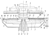
図1は両面研磨装置の要部の断面を概略的に示すもので、この両面研磨装置は、半導体ウエハや、フォトマスク等に用いられるガラスウエハあるいはセラミックスウエハといったような、薄板状をしたワークの表裏両面を研磨加工するためのもので、ラッピング装置やポリッシング装置等によって代表されるものである。 FIG. 1 schematically shows a cross section of a main part of a double-side polishing apparatus. This double-side polishing apparatus is used for a thin plate-like workpiece such as a semiconductor wafer, a glass wafer used for a photomask, or a ceramic wafer. It is for polishing both the front and back surfaces, and is represented by a lapping device or a polishing device.
上記両面研磨装置は、図2及び図3からも分かるように、同軸上に位置する円環形の上下の定盤1,2と、下定盤2の中央に位置するサンギヤ3と、該下定盤2の外周を取り囲むように位置するインターナルギヤ4とを有していて、上記両定盤1,2と、両ギヤ3,4のうち少なくともサンギヤ3とが、それぞれ駆動軸11,12,13,14を介して図示しないモーターに連結され、必要な方向に必要な速度で個別に回転駆動されるようになっている。
As can be seen from FIGS. 2 and 3, the double-side polishing apparatus includes annular upper and
上記上下の定盤1,2は、それぞれ定盤受け6,7に取り付けられることにより、着脱自在となっている。このうち上定盤1は、上記定盤受け6及び定盤吊り8を介して昇降用シリンダのロッド9に取り付けられ、この昇降用シリンダで昇降自在となっており、ワークの研磨時や後述する研磨パッドの交換時等に該上定盤1が下降すると、上記定盤吊り8に取り付けられたフック8aが駆動軸11の上端のドライバ11aに係合し、このドライバ11aを介して回転駆動されるようになっている。
The upper and
上記上定盤1及び下定盤2は、その下面又は上面に円環形をしたパッド貼着面1a及び2aを有し、これらのパッド貼着面1a,2aにそれぞれ、全体としてほぼ均一厚さを有する円環形の研磨パッド5が、該研磨パッド5の裏面全体に接着された両面接着シートを介して貼着されている。上記両定盤1,2におけるパッド貼着面1a,2aの内外径の寸法は互いに同じであり、従って、両定盤1,2に貼着される研磨パッド5,5の内外径の寸法も互いに同じである。なお、上記研磨パッド5としては、例えば硬質ウレタン製あるいは硬質不織布製のものを使用することができる。
The
また、上記サンギヤ3及びインターナルギヤ4は、リング状をした基体3a,4aの外周又は内周に、歯を構成する多数のピン3b,4bを一定のピッチで鉛直かつ円環状に配設したもので、ピン歯車の形態を有するものである。
The
上記両面研磨装置によるワークの研磨時には、図1の左半部と図2に一つのキャリヤで代表して示すように、外周に歯16aを備えた複数のキャリヤ16が、上記下定盤2上にほぼ等間隔に配置されると共に、上記両ギヤ3,4に噛合せしめられる。そして、各キャリヤ16に形成されている複数のワーク保持孔16b内にそれぞれ円板形のワークWを嵌合、保持させ、上記サンギヤ3を回転させるか又はサンギヤ3とインターナルギヤ4の両方を回転させることにより、上記各キャリヤ16をサンギヤ3の回りで自転及び公転させながら、上下両定盤1,2の間に研磨液を供給し、回転するこれらの定盤1,2の研磨パッド5,5で上記ワークWの表裏面を研磨加工する。
When the workpiece is polished by the double-side polishing apparatus, a plurality of
上記両面研磨装置はまた、上記定盤1,2に研磨パッド5を貼着する際に使用される複数の加圧ローラ20Aを備えている。この加圧ローラ20Aは、金属(好ましくは錆びにくいステンレスやその他の非鉄金属)からなる円柱形のローラ本体21と、このローラ本体21を軸線の回りに回転自在に支持するローラ軸22とからなるもので、該ローラ軸の一端を支持する支持機構25を介して装置本体に取り付けられ、該支持機構25を駆動することにより、図2及び図3に実線で示す研磨パッド貼着のための占有位置であるパッド貼着位置Xと、図2に鎖線で示す研磨パッド非貼着時の位置である収納位置Yとの間を変位するようになっている。
The double-side polishing apparatus also includes a plurality of pressure rollers 20 </ b> A used when the
上記支持機構25は、流体圧シリンダ等からなる昇降用アクチュエータ26と、この昇降用アクチュエータ26のロッド26aに取り付けられた旋回用アクチュエータ27とを有していて、この旋回用アクチュエータ27に上記加圧ローラ20Aのローラ軸22の基端部が取り付けられている。そして、図3に一つの操作途中位置を鎖線で示したように、上記昇降用アクチュエータ26による昇降操作と旋回用アクチュエータ27による旋回操作とを行うことにより、各加圧ローラ20Aを、上記パッド貼着位置Xと収納位置Yとに変位させるものである。この支持機構25による加圧ローラ20Aの駆動は、自動操作あるいは手動操作により行われる。
The
上記加圧ローラ20Aにおけるローラ本体21の軸方向長さは、上下の定盤1,2における円環形のパッド貼着面1a,2aの幅(従って研磨パッド5の幅)と同じかそれより僅かに大きく形成されている。このローラ本体21の外周面には、フッ素樹脂をコーティングしておくことが望ましい。
The axial length of the
また、上記ローラ軸22の先端には、係止用の凸部又は凹部を備えた係止部23が形成され、これに対して研磨装置の装置本体には、上記係止部23の凸部又は凹部が係止する凹部又は凸部を備えた係止受部24が形成されていて、加圧ローラ20Aが上記パッド貼着位置Xを占めるとき、これらの係止部23と係止受部24とにおける凸部と凹部とが相互に係合するようになっている。図示の例では、上記係止受部24がサンギヤ3に形成されている。この場合、サンギヤ3のピン3bをこの係止受部24として兼用し、上記ローラ軸22の係止部23にこのピン3bが係合する孔などの凹部を形成することもできる。
Further, a locking
なお、図示した例では3つの加圧ローラ20Aと支持機構25とがインターナルギア4の周りにほぼ等間隔で配設されているが、これらの加圧ローラ20Aと支持機構25との数は2つであっても4つ以上であっても良い。
In the illustrated example, the three
上記加圧ローラ20Aを使用して上下の定盤1,2に研磨パッド5を貼着する場合の作用は、次の通りである。ここでは、上下の定盤1,2に同時に研磨パッド5を貼着する場合について説明されているが、何れか一方の定盤1又は2だけに研磨パッドを貼着する場合の作用も同じである。
The operation when the
先ず、上定盤1を図1及び図3に示すように作業の邪魔にならない位置まで上昇させ、両定盤1,2のパッド貼着面に古い研磨パッドが貼着されている場合には、そのパッドを剥がし、新しい研磨パッド5を両面接着シートにより仮接着する。
First, as shown in FIGS. 1 and 3, the
新たな研磨パッド5の仮接着が終わると、図2に鎖線で示す収納位置にある各加圧ローラを、支持機構25を駆動することによって図2及び図3に実線で示すパッド貼着位置Xに変位させる。このパッド貼着位置Xにおいては、各加圧ローラ20Aが、下定盤2上に軸線を該下定盤の半径方向に向けて放射状に配置され、ローラ本体21が該下定盤2の研磨パッド5に全幅にわたり当接する。また、ローラ軸22の先端の係止部23がサンギヤ3の係止受部24に係止する。
When the temporary bonding of the
次に、図4に示すように、上昇位置にある上定盤1をその研磨パッド5が上記加圧ローラ20Aのローラ本体21に当接する位置まで下降させ、上下の定盤1,2により該ローラ本体21を挟持して上定盤1で必要な荷重(加圧力)を加える。このときの荷重は、研磨装置の規模や研磨パッド5の種類等によって最適値は異なるが、一般的には3〜20kg/cm2 程度であることが望ましい。かくして、上下の定盤1,2間に加圧ローラ20Aを介在させてローラ本体21に荷重を加えることにより、該ローラ本体21で両定盤1,2の研磨パッド5,5が、上記荷重に対応する加圧力でパッド貼着面1a,2aに押し付けられることになる。
Next, as shown in FIG. 4, the
そして、上記サンギヤ3とインターナルギヤ4とを非回転の状態に固定し、上下の定盤1,2だけをゆっくりした速度で互いに逆方向に等速で回転させる。これにより、各加圧ローラ20Aのローラ本体21は、一定の位置において、回転する両定盤に追随してローラ軸22の回りを従動回転し、これらの定盤1,2と一緒に回転する研磨パッド5,5を押圧してパッド貼着面1a,2aに圧着させる。
上記研磨パッド5,5の貼着が終わると、上定盤1を上昇させ、支持機構25により各加圧ローラ20Aを収納位置に変位させる。
Then, the
When the
かくして、複数の加圧ローラ20Aを上下の定盤1,2間に介在させ、荷重を加えた状態で両定盤1,2を互いに逆向きに回転させるだけの非常に簡単でしかも合理的な方法により、各加圧ローラ20Aのローラ本体21で上下両定盤1,2の研磨パッド5,5を機械的に加圧し、パッド貼着面に圧着することができる。この場合、上下の定盤1,2を逆向きに回転させることで上記ローラ本体21を従動回転させるようにしているから、該ローラ本体21が上下何れの定盤1,2の研磨パッド5,5とも擦れ合うことがなく、該研磨パッド5,5の損傷や摩耗あるいは目潰れ等を生じることがない。しかも、上下の定盤1,2によってローラ本体21全体が同時にかつ均等に加圧されるため、このローラ本体21による加圧力が研磨パッド5,5全体に均等に作用することになり、このため接着むらが発生せず、パッド全体を定盤1,2に対して均一に貼着することができる。
Thus, it is very simple and rational that a plurality of
図5は本発明の第2実施形態を示すもので、この第2実施形態の両面研磨装置が上記第1実施形態の両面研磨装置と異なる点は、加圧ローラ20Bにおけるローラ本体21が、定盤1,2のパッド貼着面1a,2aの幅より短い長さに形成されると共に、ローラ軸22に沿って移動自在なるように構成されている点である。即ち、各加圧ローラ20Bにおけるローラ軸22の外周には雄ねじが設けられ、ローラ本体21の内周にはこの雄ねじと噛み合う雌ねじが設けられていて、パッド貼着時にローラ本体21が上下の定盤1,2の回転に追随して従動回転するのに伴い、このローラ本体21が上記ローラ軸22に沿って移動するようになっている。このとき、研磨パッド5,5とパッド貼着面1a,2aとの間に介在する空気は、ローラ本体21により押し動かされて外部に排出され、それらの間に封じ込められることはない。
FIG. 5 shows a second embodiment of the present invention. The difference between the double-side polishing apparatus of the second embodiment and the double-side polishing apparatus of the first embodiment is that the
上記加圧ローラ20Bにおけるローラ本体21の好ましい長さは、パッド貼着面1a,2aの幅の1/2〜1/3程度であるが、それ以外の長さであっても構わない。また、パッド貼着時にこのローラ本体21は、定盤1,2の内周側から外周側に向けて移動させても、外周側から内周側に向けて移動させても良い。
The preferred length of the
この第2実施形態における上記以外の構成及び作用と好ましい変形例とについては、上記第1実施形態と同じであるから、それらの主要な同一構成部分に第1実施形態の場合と同じ符号を付してその説明は省略する。 Since the configurations and operations other than those described above and preferred modifications in the second embodiment are the same as those in the first embodiment, the same reference numerals as those in the first embodiment are assigned to the same identical components. The description is omitted.
図6は本発明の第3実施形態を示すもので、この第3実施形態の両面研磨装置が上記第2実施形態の両面研磨装置と異なる点は、複数の加圧ローラ20Cが研磨装置に対して個別に着脱自在となっている点である。 FIG. 6 shows a third embodiment of the present invention. The difference between the double-side polishing apparatus of the third embodiment and the double-side polishing apparatus of the second embodiment is that a plurality of pressure rollers 20C are different from the polishing apparatus. It is a point that can be detached individually.
即ち、上記加圧ローラ20Cは、図7からも分かるように、定盤1,2のパッド貼着面1a,2aの幅より長さが短いローラ本体21と、このローラ本体12を回転自在かつ移動自在に支持するローラ22軸と、このローラ軸22の両端に形成された係止部23a,23bとを有していて、これらの係止部23a,23bを、研磨装置における下定盤2の内外周側の部分に形成された係止受部24a,24bに係止させることにより、該研磨装置に取り付けられるものである。この場合、2つの加圧ローラ20Cを使用し、これらの加圧ローラを定盤1,2の直径方向に一列に並べて取り付けるようにしても良いが、好ましくは、図6に示すように、3つ以上の加圧ローラ20Cを等間隔で放射状に配設することである。
That is, as can be seen from FIG. 7, the pressure roller 20C has a roller
上記ローラ軸22の外周には雄ねじが設けられ、ローラ本体21の内周にはこの雄ねじと噛み合う雌ねじが設けられており、パッド貼着時にローラ本体21が上下の定盤1,2の回転に追随して従動回転するのに伴い、このローラ本体21が上記ローラ軸22に沿って移動するようになっている。
A male screw is provided on the outer periphery of the
また、上記係止部23a,23bは、ブロック形の部材の下面に1つ又は複数の係止孔28を備えた構成を有していて、この係止孔28を上記サンギヤ3及びインターナルギヤ4の1つ又は複数のピン3b,4bに係合させることで、研磨装置に取り付けられるようになっている。従って、研磨装置側の上記係止受部24a,24bは、上記サンギヤ3及びインターナルギヤ4の上記ピン3b,4bによって構成されていることになる。
しかし、上記係止部及び係止受部はこのようなものに限らず、係止専用のピンや突起あるいは孔などの相互に係合し合う凸部と凹部とを有するものであれば、どのような形態のものであっても良い。
The engaging
However, the locking portion and the locking receiving portion are not limited to this, and any locking pins and protrusions that have engaging protrusions and recesses such as pins, protrusions, or holes dedicated to locking can be used. The thing of such a form may be sufficient.
この第3実施形態における上記以外の構成及び作用と好ましい変形例とについては、上記第2実施形態と同じであるから、それらの主要な同一構成部分に第2実施形態のものと同じ符号を付してその説明は省略する。 Since the configuration and operation of the third embodiment other than those described above and the preferred modification are the same as those of the second embodiment, the same reference numerals as those of the second embodiment are assigned to the main same components. The description is omitted.
なお、上記実施形態においては、サンギヤ3及びインターナルギヤ4がピン歯車としての形態を有していて、多数のピン3b,4bによって歯が形成されているが、通常の平歯車のように、内外周に中心軸線と平行する直線歯を放射状に備えたものであっても良い。このようにサンギヤ3及びインターナルギヤ4が直線歯を備えたものである場合、上記加圧ローラ20A,20B,20Cにおける係止部23,23a,23bを、上記直線歯と同様の歯状の凹凸を有するように形成し、この凹凸をサンギヤ3又はインターナルギヤ4の直線歯に噛合させるように構成することもできる。
In the above embodiment, the
1 上定盤
2 下定盤
1a,2a パッド貼着面
3 サンギヤ
4 インターナルギヤ
5 研磨パッド
16 キャリヤ
20A,20B,20C 加圧ローラ
21 ローラ本体
22 ローラ軸
23,23a,23b 係止部
24,24a,24b 係止受部
25 支持機構
X 貼着位置
Y 収納位置
W ワーク
DESCRIPTION OF
Claims (4)
上記キャリヤを駆動するためのサンギヤ及びインターナルギヤ、
円柱形をしたローラ本体と、該ローラ本体を回転自在に支持するローラ軸とからなっていて、アクチュエータで駆動される支持機構を介して装置本体に取り付けられ、該支持機構を上記アクチュエータで駆動することにより、上記ローラ本体が上下の定盤間に半径方向に介在した状態でこれら両定盤の回転に追随して従動回転しながら研磨パッドを加圧するパッド貼着位置と、上下の定盤から離れた収納位置との間を変位する加圧ローラ、
を有することを特徴とする研磨パッド用加圧ローラを備えた両面研磨装置。 An upper surface plate and a lower surface plate that have an annular pad attachment surface and an annular polishing pad attached to the attachment surface, and polish by sandwiching a workpiece held by the carrier from both sides,
A sun gear and an internal gear for driving the carrier;
A cylindrical roller body and a roller shaft that rotatably supports the roller body are attached to the apparatus body via a support mechanism driven by an actuator , and the support mechanism is driven by the actuator . In the state where the roller body is interposed between the upper and lower surface plates in the radial direction, the pad attaching position that presses the polishing pad while following the rotation of both surface plates and following the rotation, and from the upper and lower surface plates A pressure roller that displaces between remote storage positions;
A double-side polishing apparatus provided with a pressure roller for a polishing pad.
Priority Applications (1)
| Application Number | Priority Date | Filing Date | Title |
|---|---|---|---|
| JP2005109991A JP4693468B2 (en) | 2005-04-06 | 2005-04-06 | Double-side polishing device with pressure roller for applying polishing pad |
Applications Claiming Priority (1)
| Application Number | Priority Date | Filing Date | Title |
|---|---|---|---|
| JP2005109991A JP4693468B2 (en) | 2005-04-06 | 2005-04-06 | Double-side polishing device with pressure roller for applying polishing pad |
Related Child Applications (1)
| Application Number | Title | Priority Date | Filing Date |
|---|---|---|---|
| JP2008070144A Division JP2008149459A (en) | 2008-03-18 | 2008-03-18 | Pressure roller for applying polishing pad and applying method of polishing pad with pressure roller in double-sided polishing device |
Publications (3)
| Publication Number | Publication Date |
|---|---|
| JP2006289523A JP2006289523A (en) | 2006-10-26 |
| JP2006289523A5 JP2006289523A5 (en) | 2008-05-01 |
| JP4693468B2 true JP4693468B2 (en) | 2011-06-01 |
Family
ID=37410669
Family Applications (1)
| Application Number | Title | Priority Date | Filing Date |
|---|---|---|---|
| JP2005109991A Active JP4693468B2 (en) | 2005-04-06 | 2005-04-06 | Double-side polishing device with pressure roller for applying polishing pad |
Country Status (1)
| Country | Link |
|---|---|
| JP (1) | JP4693468B2 (en) |
Families Citing this family (7)
| Publication number | Priority date | Publication date | Assignee | Title |
|---|---|---|---|---|
| KR101443459B1 (en) | 2012-12-27 | 2014-09-19 | 주식회사 엘지실트론 | Niddle dresser and wafer double side poliching apparatus with it |
| KR101453680B1 (en) | 2013-07-09 | 2014-10-22 | 주식회사 엘지실트론 | Double side of wafer polishing apparatus and roller to removal double side polishing pad for it |
| EP4000806A1 (en) | 2020-11-16 | 2022-05-25 | Siltronic AG | Method for polishing semiconductor wafers on both sides between a lower polishing plate and an upper polishing plate |
| EP4000802A1 (en) | 2020-11-17 | 2022-05-25 | Siltronic AG | Method for polishing semiconductor wafers on both sides between a lower polishing plate and an upper polishing plate |
| CN115351721B (en) * | 2022-06-24 | 2023-11-24 | 淮安澳洋顺昌光电技术有限公司 | Automatic polishing cloth pasting device and method for polishing machine |
| EP4306262A1 (en) | 2022-07-13 | 2024-01-17 | Siltronic AG | Method for polishing semiconductor wafers on both sides between a lower polishing plate and an upper polishing plate |
| EP4321298A1 (en) | 2022-08-12 | 2024-02-14 | Siltronic AG | Device and method for pressing an upper polishing cloth against an upper polishing plate of a machine for simultaneously polishing a front side and a back side of a semiconductor wafer |
Citations (6)
| Publication number | Priority date | Publication date | Assignee | Title |
|---|---|---|---|---|
| JPS62102974A (en) * | 1985-10-29 | 1987-05-13 | Hoya Corp | Working pad and flattening machine |
| JPH09225812A (en) * | 1995-08-24 | 1997-09-02 | Matsushita Electric Ind Co Ltd | Polishing method and device for semiconductor substrate |
| JPH11300599A (en) * | 1998-04-23 | 1999-11-02 | Speedfam-Ipec Co Ltd | Method and device for grinding one side of work |
| JPH11320387A (en) * | 1998-05-07 | 1999-11-24 | Speedfam-Ipec Co Ltd | Sticking method for polishing pad |
| JP2000024909A (en) * | 1998-05-07 | 2000-01-25 | Ebara Corp | Polishing device |
| JP2006346808A (en) * | 2005-06-15 | 2006-12-28 | Mimasu Semiconductor Industry Co Ltd | Grinding pad sticking method and workpiece producing method |
-
2005
- 2005-04-06 JP JP2005109991A patent/JP4693468B2/en active Active
Patent Citations (6)
| Publication number | Priority date | Publication date | Assignee | Title |
|---|---|---|---|---|
| JPS62102974A (en) * | 1985-10-29 | 1987-05-13 | Hoya Corp | Working pad and flattening machine |
| JPH09225812A (en) * | 1995-08-24 | 1997-09-02 | Matsushita Electric Ind Co Ltd | Polishing method and device for semiconductor substrate |
| JPH11300599A (en) * | 1998-04-23 | 1999-11-02 | Speedfam-Ipec Co Ltd | Method and device for grinding one side of work |
| JPH11320387A (en) * | 1998-05-07 | 1999-11-24 | Speedfam-Ipec Co Ltd | Sticking method for polishing pad |
| JP2000024909A (en) * | 1998-05-07 | 2000-01-25 | Ebara Corp | Polishing device |
| JP2006346808A (en) * | 2005-06-15 | 2006-12-28 | Mimasu Semiconductor Industry Co Ltd | Grinding pad sticking method and workpiece producing method |
Also Published As
| Publication number | Publication date |
|---|---|
| JP2006289523A (en) | 2006-10-26 |
Similar Documents
| Publication | Publication Date | Title |
|---|---|---|
| JP4693468B2 (en) | Double-side polishing device with pressure roller for applying polishing pad | |
| JP4207153B2 (en) | Substrate polishing method and apparatus | |
| JP2007268679A (en) | Correction implement for polishing pad for double-sided polishing device and double-sided polishing device equipped therewith | |
| JP5573061B2 (en) | Grinding method and apparatus for polishing cloth of double-side polishing apparatus | |
| JP4307411B2 (en) | Polishing pad pasting method and workpiece manufacturing method | |
| JP2010188488A (en) | Double-side grinding device | |
| JP4777727B2 (en) | Polishing pad pasting method and polishing pad pasting jig | |
| KR101097074B1 (en) | Substrate polishing apparatus and substrate polishing method | |
| JP2002046059A (en) | Base polishing apparatus | |
| JP2008149459A (en) | Pressure roller for applying polishing pad and applying method of polishing pad with pressure roller in double-sided polishing device | |
| JP4584755B2 (en) | Pressure roller for attaching polishing pad in double-side polishing apparatus, and method for attaching polishing pad with pressure roller | |
| JPH09314457A (en) | One side grinding device having dresser | |
| JP2011000644A (en) | Surface polishing apparatus and method for removing workpiece | |
| JP5807583B2 (en) | Carrier pressing mechanism, polishing apparatus, glass substrate polishing method, and glass substrate manufacturing method | |
| CN102416597A (en) | Grinding device and grinding method of baseplate | |
| JP3872967B2 (en) | Double-side polishing apparatus, double-side polishing method and double-side polishing support member | |
| JP2021181138A (en) | Abrasive pad sticking method for double-sided grinding device | |
| JP3565480B2 (en) | Substrate polishing method and substrate polishing apparatus | |
| JP2010042554A (en) | Fine printing device equipped with cleaning mechanism for blanket surface | |
| CN102407491A (en) | Finishing component and finishing method for grinding pad | |
| WO2014010384A1 (en) | Polishing device for plate-like body, and polishing method for plate-like body | |
| JP2006068888A (en) | Manufacturing method of surface table and surface polishing apparatus | |
| CN218658449U (en) | Polishing disk finishing device of double-sided polishing machine | |
| JP6635840B2 (en) | Stripping device, flat surface polishing device and stripping method | |
| JP2006289522A5 (en) |
Legal Events
| Date | Code | Title | Description |
|---|---|---|---|
| A521 | Request for written amendment filed |
Free format text: JAPANESE INTERMEDIATE CODE: A523 Effective date: 20080318 |
|
| A621 | Written request for application examination |
Free format text: JAPANESE INTERMEDIATE CODE: A621 Effective date: 20080318 |
|
| A977 | Report on retrieval |
Free format text: JAPANESE INTERMEDIATE CODE: A971007 Effective date: 20100401 |
|
| TRDD | Decision of grant or rejection written | ||
| A01 | Written decision to grant a patent or to grant a registration (utility model) |
Free format text: JAPANESE INTERMEDIATE CODE: A01 Effective date: 20110208 |
|
| A01 | Written decision to grant a patent or to grant a registration (utility model) |
Free format text: JAPANESE INTERMEDIATE CODE: A01 |
|
| A61 | First payment of annual fees (during grant procedure) |
Free format text: JAPANESE INTERMEDIATE CODE: A61 Effective date: 20110222 |
|
| FPAY | Renewal fee payment (event date is renewal date of database) |
Free format text: PAYMENT UNTIL: 20140304 Year of fee payment: 3 |
|
| R150 | Certificate of patent or registration of utility model |
Ref document number: 4693468 Country of ref document: JP Free format text: JAPANESE INTERMEDIATE CODE: R150 Free format text: JAPANESE INTERMEDIATE CODE: R150 |
|
| R250 | Receipt of annual fees |
Free format text: JAPANESE INTERMEDIATE CODE: R250 |
|
| R250 | Receipt of annual fees |
Free format text: JAPANESE INTERMEDIATE CODE: R250 |
|
| R250 | Receipt of annual fees |
Free format text: JAPANESE INTERMEDIATE CODE: R250 |
|
| R250 | Receipt of annual fees |
Free format text: JAPANESE INTERMEDIATE CODE: R250 |
|
| R250 | Receipt of annual fees |
Free format text: JAPANESE INTERMEDIATE CODE: R250 |
|
| R250 | Receipt of annual fees |
Free format text: JAPANESE INTERMEDIATE CODE: R250 |
|
| R250 | Receipt of annual fees |
Free format text: JAPANESE INTERMEDIATE CODE: R250 |
|
| R250 | Receipt of annual fees |
Free format text: JAPANESE INTERMEDIATE CODE: R250 |
|
| R250 | Receipt of annual fees |
Free format text: JAPANESE INTERMEDIATE CODE: R250 |
|
| R250 | Receipt of annual fees |
Free format text: JAPANESE INTERMEDIATE CODE: R250 |
|
| R250 | Receipt of annual fees |
Free format text: JAPANESE INTERMEDIATE CODE: R250 |