JP4575682B2 - 投射型映像表示装置及び偏光分離用構造体 - Google Patents
投射型映像表示装置及び偏光分離用構造体 Download PDFInfo
- Publication number
- JP4575682B2 JP4575682B2 JP2004059569A JP2004059569A JP4575682B2 JP 4575682 B2 JP4575682 B2 JP 4575682B2 JP 2004059569 A JP2004059569 A JP 2004059569A JP 2004059569 A JP2004059569 A JP 2004059569A JP 4575682 B2 JP4575682 B2 JP 4575682B2
- Authority
- JP
- Japan
- Prior art keywords
- light
- polarization separation
- polarization
- wire grid
- projection
- Prior art date
- Legal status (The legal status is an assumption and is not a legal conclusion. Google has not performed a legal analysis and makes no representation as to the accuracy of the status listed.)
- Expired - Fee Related
Links
Images
Landscapes
- Projection Apparatus (AREA)
- Polarising Elements (AREA)
- Diffracting Gratings Or Hologram Optical Elements (AREA)
Description
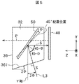
Nsin(β+θ)<1 …(数3)
数2と数3とから下記数4が得られる。
−sin−1[(1/N)sin〔tan−1{1/(2F)}〕]…(数4)
ただし、数4において、θ>0である。
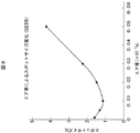
例えば、媒質の光の屈折率Nを1.45、Fを3とすれば、数4から主光線の空気層界面での臨界入射角θmは37.1°となり、数5から、φは7.9°以上にする必要がある。φを7.9°以上とすれば、数4が満たされるため、空気層界面での全反射は生じない。
11…光源、
12…リフレクタ、
13、14…マルチレンズアレイ、
15…平板型偏光変換手段、
16…集光レンズ、
21、22…フィールドレンズ、
23…リレーレンズ、
18、19…ダイクロイックミラー、
20…色分離手段、
24…全反射ミラー、
29、291、292、293…入射側偏光板、
30、301、302、303、30A、30B、30C…偏光分離手段、
31、32…液体、
33…直角プリズム、
34…プリズム、
35…透光性容器、
36…金属容器、
41、411、412、413…出射側偏光板、
40、401、402、403…反射型液晶パネル、
42、43…1/2波長位相差板、
44…クロスダイクロイックプリズム、
45…投射レンズユニット、
50、60…ワイヤグリッド型偏光分離素子、
51、61…透光性基板、
56、66…空気層。
Claims (4)
- 光源側からの光を偏光変換してライトバルブに照射し、映像信号に応じた光学像を形成して拡大投射する投射型映像表示装置であって、
格子構造に基づく回折により光を偏光分離する偏光分離面が、光透過性の液体中において空気層を介し光透過性の平板上に形成され、上記ライトバルブに照射された光及び該ライトバルブで変調された光を偏光分離する偏光分離手段と、
上記偏光分離された光を色合成する色合成手段と、
上記色合成された光を拡大投射する投射レンズユニットと、
上記ライトバルブを駆動する駆動回路と、
を備えた構成を特徴とする投射型映像表示装置。 - 光源側からの光を映像表示素子に照射し、映像信号に応じた光学像を形成して拡大投射する投射型映像表示装置であって、
光源側からの光の偏光方向を揃えP偏光光またはS偏光光を形成する偏光変換手段と、
上記偏光変換された偏光光を、R、G、Bの各色光に分離する分離手段と、
上記分離された各色光の偏光光が照射され映像信号に基づき該偏光光を変調するライトバルブと、
格子構造に基づく回折により光を偏光分離する偏光分離面が、光透過性の液体中において空気層を介し光透過性の平板上に形成され、上記ライトバルブに照射された光及び該ライトバルブで変調された光を偏光分離する偏光分離手段と、
上記偏光分離された光を色合成する色合成手段と、
上記色合成された光を拡大投射する投射レンズユニットと、
上記ライトバルブを駆動する駆動回路と、
を備えた構成を特徴とする投射型映像表示装置。 - 上記ライトバルブは、反射型ライトバルブである請求項1または請求項2に記載の投射型映像表示装置。
- 入射された光を偏光分離する偏光分離用構造体であって、
格子構造に基づく回折により光を偏光分離する偏光分離面が、光透過性の液体中において空気層を介し光透過性の平板上に形成された構成を特徴とする偏光分離用構造体。
Priority Applications (3)
| Application Number | Priority Date | Filing Date | Title |
|---|---|---|---|
| JP2004059569A JP4575682B2 (ja) | 2004-03-03 | 2004-03-03 | 投射型映像表示装置及び偏光分離用構造体 |
| CNB2004100889873A CN100337143C (zh) | 2004-03-03 | 2004-11-23 | 光学单元以及使用该光学单元的投影型图像显示装置 |
| US11/061,055 US7255444B2 (en) | 2004-03-03 | 2005-02-18 | Optical unit and projection-type image display apparatus using the same |
Applications Claiming Priority (1)
| Application Number | Priority Date | Filing Date | Title |
|---|---|---|---|
| JP2004059569A JP4575682B2 (ja) | 2004-03-03 | 2004-03-03 | 投射型映像表示装置及び偏光分離用構造体 |
Publications (3)
| Publication Number | Publication Date |
|---|---|
| JP2005250057A JP2005250057A (ja) | 2005-09-15 |
| JP2005250057A5 JP2005250057A5 (ja) | 2007-03-22 |
| JP4575682B2 true JP4575682B2 (ja) | 2010-11-04 |
Family
ID=35030598
Family Applications (1)
| Application Number | Title | Priority Date | Filing Date |
|---|---|---|---|
| JP2004059569A Expired - Fee Related JP4575682B2 (ja) | 2004-03-03 | 2004-03-03 | 投射型映像表示装置及び偏光分離用構造体 |
Country Status (1)
| Country | Link |
|---|---|
| JP (1) | JP4575682B2 (ja) |
Families Citing this family (3)
| Publication number | Priority date | Publication date | Assignee | Title |
|---|---|---|---|---|
| KR100838066B1 (ko) | 2006-07-14 | 2008-06-16 | 삼성에스디아이 주식회사 | 유기 발광 장치 |
| JP2012189930A (ja) | 2011-03-14 | 2012-10-04 | Seiko Epson Corp | プロジェクター |
| CN114077143B (zh) * | 2021-10-29 | 2024-04-30 | 歌尔光学科技有限公司 | 投影装置、投影装置的控制方法及投影系统 |
Citations (13)
| Publication number | Priority date | Publication date | Assignee | Title |
|---|---|---|---|---|
| JPH0527701U (ja) * | 1991-09-13 | 1993-04-09 | パイオニア株式会社 | 投射型表示装置 |
| JPH05323118A (ja) * | 1992-05-20 | 1993-12-07 | Matsushita Electric Ind Co Ltd | 偏光装置および該偏光装置を用いた投写型表示装置 |
| JPH05323121A (ja) * | 1992-05-22 | 1993-12-07 | Pioneer Electron Corp | 投射型表示装置 |
| JPH06317771A (ja) * | 1993-05-07 | 1994-11-15 | Victor Co Of Japan Ltd | 表示装置 |
| JPH0868966A (ja) * | 1994-08-30 | 1996-03-12 | Victor Co Of Japan Ltd | 偏光ビームスプリッタを用いた表示装置 |
| JPH10326080A (ja) * | 1997-03-24 | 1998-12-08 | Sony Corp | 映像表示装置及び映像表示方法 |
| JPH11202432A (ja) * | 1998-01-16 | 1999-07-30 | Sharp Corp | 投射型画像表示装置 |
| JPH11202132A (ja) * | 1998-01-20 | 1999-07-30 | Fujitsu General Ltd | 偏光プリズム及び反射型光変調プロジェクタ |
| WO2001013162A1 (fr) * | 1999-08-13 | 2001-02-22 | Seiko Epson Corporation | Illuminateur a lumiere polarisee et affichage de projection |
| WO2002095496A1 (en) * | 2001-05-21 | 2002-11-28 | Moxtek | Image projection system with a polarizing beam splitter |
| JP2002365591A (ja) * | 2001-06-04 | 2002-12-18 | Hitachi Ltd | 光学ユニット及びそれを用いた映像表示装置 |
| JP2003195223A (ja) * | 2001-10-01 | 2003-07-09 | Sony Corp | プリズム、投影装置及び光学部材 |
| JP2005250054A (ja) * | 2004-03-03 | 2005-09-15 | Hitachi Ltd | 投射型映像表示装置及びそれに用いる光学ユニット |
-
2004
- 2004-03-03 JP JP2004059569A patent/JP4575682B2/ja not_active Expired - Fee Related
Patent Citations (13)
| Publication number | Priority date | Publication date | Assignee | Title |
|---|---|---|---|---|
| JPH0527701U (ja) * | 1991-09-13 | 1993-04-09 | パイオニア株式会社 | 投射型表示装置 |
| JPH05323118A (ja) * | 1992-05-20 | 1993-12-07 | Matsushita Electric Ind Co Ltd | 偏光装置および該偏光装置を用いた投写型表示装置 |
| JPH05323121A (ja) * | 1992-05-22 | 1993-12-07 | Pioneer Electron Corp | 投射型表示装置 |
| JPH06317771A (ja) * | 1993-05-07 | 1994-11-15 | Victor Co Of Japan Ltd | 表示装置 |
| JPH0868966A (ja) * | 1994-08-30 | 1996-03-12 | Victor Co Of Japan Ltd | 偏光ビームスプリッタを用いた表示装置 |
| JPH10326080A (ja) * | 1997-03-24 | 1998-12-08 | Sony Corp | 映像表示装置及び映像表示方法 |
| JPH11202432A (ja) * | 1998-01-16 | 1999-07-30 | Sharp Corp | 投射型画像表示装置 |
| JPH11202132A (ja) * | 1998-01-20 | 1999-07-30 | Fujitsu General Ltd | 偏光プリズム及び反射型光変調プロジェクタ |
| WO2001013162A1 (fr) * | 1999-08-13 | 2001-02-22 | Seiko Epson Corporation | Illuminateur a lumiere polarisee et affichage de projection |
| WO2002095496A1 (en) * | 2001-05-21 | 2002-11-28 | Moxtek | Image projection system with a polarizing beam splitter |
| JP2002365591A (ja) * | 2001-06-04 | 2002-12-18 | Hitachi Ltd | 光学ユニット及びそれを用いた映像表示装置 |
| JP2003195223A (ja) * | 2001-10-01 | 2003-07-09 | Sony Corp | プリズム、投影装置及び光学部材 |
| JP2005250054A (ja) * | 2004-03-03 | 2005-09-15 | Hitachi Ltd | 投射型映像表示装置及びそれに用いる光学ユニット |
Also Published As
| Publication number | Publication date |
|---|---|
| JP2005250057A (ja) | 2005-09-15 |
Similar Documents
| Publication | Publication Date | Title |
|---|---|---|
| US7255444B2 (en) | Optical unit and projection-type image display apparatus using the same | |
| JP4652110B2 (ja) | 投射型映像表示装置 | |
| US7502078B2 (en) | Projection type display apparatus with means for supplying an air cooling stream to a gap between a light receiving surface of a prism and a third surface of a closed triangular prismatic housing | |
| JP2007011248A (ja) | 投射型表示装置 | |
| KR20040049778A (ko) | 투사형 영상 표시 장치 | |
| JP4880957B2 (ja) | 照明光学系およびそれを用いた投射型表示装置 | |
| US7354162B2 (en) | Projector | |
| JPH08114780A (ja) | 投影型カラー液晶表示装置 | |
| JP2006145644A (ja) | 偏光分離装置及びそれを用いた投射型表示装置 | |
| JP2006276826A (ja) | 反射型投射表示装置 | |
| JP2007226092A (ja) | 光学素子の製造方法及びプロジェクタの製造方法並びに光学素子及びプロジェクタ | |
| US7472995B2 (en) | Wavelength-selective polarization conversion element, projection displaying optical system and image projection apparatus | |
| JP2002182195A (ja) | 投射型表示装置 | |
| JP4258293B2 (ja) | 投射型映像表示装置 | |
| JP3951897B2 (ja) | 偏光変換ユニット及びこれを用いたプロジェクタ | |
| JP4539319B2 (ja) | 投射型表示装置 | |
| JP2003131212A (ja) | 投写型表示装置 | |
| JP4575682B2 (ja) | 投射型映像表示装置及び偏光分離用構造体 | |
| JP4444745B2 (ja) | 偏光分離素子および画像投射装置 | |
| JP2007279763A (ja) | 投射型映像表示装置 | |
| US8064134B2 (en) | Optical element and image projection apparatus | |
| JP2001083604A (ja) | 光束圧縮手段、光学エンジン及びこれを用いた映像表示装置 | |
| JP4939070B2 (ja) | 照明光学系および画像投射装置 | |
| JP3659209B2 (ja) | 光学ユニット及びそれを用いた映像表示装置 | |
| JP2768345B2 (ja) | 液晶プロジェクタ |
Legal Events
| Date | Code | Title | Description |
|---|---|---|---|
| A521 | Written amendment |
Free format text: JAPANESE INTERMEDIATE CODE: A523 Effective date: 20070206 |
|
| A621 | Written request for application examination |
Free format text: JAPANESE INTERMEDIATE CODE: A621 Effective date: 20070206 |
|
| RD02 | Notification of acceptance of power of attorney |
Free format text: JAPANESE INTERMEDIATE CODE: A7422 Effective date: 20070206 |
|
| A977 | Report on retrieval |
Free format text: JAPANESE INTERMEDIATE CODE: A971007 Effective date: 20100311 |
|
| A131 | Notification of reasons for refusal |
Free format text: JAPANESE INTERMEDIATE CODE: A131 Effective date: 20100323 |
|
| A521 | Written amendment |
Free format text: JAPANESE INTERMEDIATE CODE: A523 Effective date: 20100520 |
|
| TRDD | Decision of grant or rejection written | ||
| A01 | Written decision to grant a patent or to grant a registration (utility model) |
Free format text: JAPANESE INTERMEDIATE CODE: A01 Effective date: 20100803 |
|
| A01 | Written decision to grant a patent or to grant a registration (utility model) |
Free format text: JAPANESE INTERMEDIATE CODE: A01 |
|
| A61 | First payment of annual fees (during grant procedure) |
Free format text: JAPANESE INTERMEDIATE CODE: A61 Effective date: 20100820 |
|
| R150 | Certificate of patent or registration of utility model |
Free format text: JAPANESE INTERMEDIATE CODE: R150 |
|
| FPAY | Renewal fee payment (event date is renewal date of database) |
Free format text: PAYMENT UNTIL: 20130827 Year of fee payment: 3 |
|
| S111 | Request for change of ownership or part of ownership |
Free format text: JAPANESE INTERMEDIATE CODE: R313111 |
|
| R350 | Written notification of registration of transfer |
Free format text: JAPANESE INTERMEDIATE CODE: R350 |
|
| S111 | Request for change of ownership or part of ownership |
Free format text: JAPANESE INTERMEDIATE CODE: R313111 |
|
| R350 | Written notification of registration of transfer |
Free format text: JAPANESE INTERMEDIATE CODE: R350 |
|
| LAPS | Cancellation because of no payment of annual fees |


