JP4518494B2 - Land pattern inspection method and inspection apparatus - Google Patents
Land pattern inspection method and inspection apparatus Download PDFInfo
- Publication number
- JP4518494B2 JP4518494B2 JP2005091990A JP2005091990A JP4518494B2 JP 4518494 B2 JP4518494 B2 JP 4518494B2 JP 2005091990 A JP2005091990 A JP 2005091990A JP 2005091990 A JP2005091990 A JP 2005091990A JP 4518494 B2 JP4518494 B2 JP 4518494B2
- Authority
- JP
- Japan
- Prior art keywords
- image
- hole
- land
- circle
- land pattern
- Prior art date
- Legal status (The legal status is an assumption and is not a legal conclusion. Google has not performed a legal analysis and makes no representation as to the accuracy of the status listed.)
- Expired - Fee Related
Links
Images


Classifications
-
- E—FIXED CONSTRUCTIONS
- E01—CONSTRUCTION OF ROADS, RAILWAYS, OR BRIDGES
- E01F—ADDITIONAL WORK, SUCH AS EQUIPPING ROADS OR THE CONSTRUCTION OF PLATFORMS, HELICOPTER LANDING STAGES, SIGNS, SNOW FENCES, OR THE LIKE
- E01F8/00—Arrangements for absorbing or reflecting air-transmitted noise from road or railway traffic
- E01F8/0005—Arrangements for absorbing or reflecting air-transmitted noise from road or railway traffic used in a wall type arrangement
- E01F8/0023—Details, e.g. foundations
Description
本発明は、プリント基板の検査方法および検査装置に関し、より特定的には、プリント基板上のランドパターンの検査方法および検査装置に関する。 The present invention relates to a printed circuit board inspection method and inspection apparatus, and more particularly to a land pattern inspection method and inspection apparatus on a printed circuit board.
電子部品等が実装されるプリント基板の表面には、所定の回路を構成するのに必要な導体配線がパターン形成される。このパターンの1つとして、部品の取り付けや接続に用いるためのランドというパターンがある。そして、このランドに発生する欠陥として、「ランド座切れ」(図16(A)参照)と「ランド欠損」(図16(B)参照)がある。このような欠陥が存在すると、導通が不完全になり、当該基板を使用している製品等が誤動作を起こす可能性がある。そのため、上記のようなランド欠陥の検出は、プリント基板検査において重要な検査項目の1つである。 On the surface of the printed circuit board on which electronic components and the like are mounted, a conductor wiring necessary for constituting a predetermined circuit is formed in a pattern. As one of these patterns, there is a pattern called land for use in mounting and connecting parts. As defects generated in the land, there are a “land break” (see FIG. 16A) and a “land defect” (see FIG. 16B). If such a defect exists, conduction may be incomplete, and a product using the substrate may malfunction. For this reason, detection of land defects as described above is one of the important inspection items in printed circuit board inspection.
上記のようなランドの欠陥を検査するために一般に用いられる方法として、測長子を用いてスルーホールの直径を測定する方法がある(例えば、特許文献1)。図17は、当該スルーホールの直径測定による欠陥検査方法を示す図である。図17(A)に示すように、放射状の測長子171を用いて、円の直径を測定する。そして、全ての直径が等しければ(図17(A))、ランドには欠陥がないとされる。一方、図17(B)に示すように、ランドに座切れがある場合、座切れ部分にかかる測長子の直径が他の直径に比べて長くなる。すなわち、全ての直径が等しくはならないため、この場合は、ランドに欠陥があるとされる。
しかしながら、上述したような上記特許文献1に開示された方法においては、ランドの欠陥が微細な場合に検出できないという問題点があった。例えば、図17(C)に示すように、ランドの座切れが微細な場合は、測長子171が欠陥部分にかからずに、その結果、全ての直径が等しくなる。その結果、欠陥があるにも関わらず、正常と判定されてしまう。このような問題を回避するために、測長子171の本数を増やすという方法もあるが、この場合でも、図17(D)に示すように、更に微細な欠陥がある場合は、やはり検出できないこととなる。これは、ランド欠損の場合についても同様のことが言える。
However, the method disclosed in
それ故に、本発明の目的は、スルーホールの直径を放射状の測長子で計測する方法でも検出できないような、ランドの微細な欠陥を検出できるランドパターン検査方法及び検査装置を提供することである。 SUMMARY OF THE INVENTION Therefore, an object of the present invention is to provide a land pattern inspection method and inspection apparatus capable of detecting a fine defect in a land that cannot be detected even by a method of measuring the diameter of a through hole with a radial length gauge.
上記目的を達成するために、本発明は以下のような構成を採用した。 In order to achieve the above object, the present invention employs the following configuration.
第1の発明は、被検査物に形成されたランドパターンを撮像したオブジェクト画像と当該ランドパターンのマスター画像とを比較して、当該被検査物のランドパターン形状を検査するランドパターン検査方法であって、被検査物に形成されたランドパターンを撮像して得られる画像を2値化したオブジェクト画像を作成するオブジェクト画像作成ステップと、オブジェクト画像からランドパターンに形成されているスルーホールの直径を計測する穴認識ステップと、計測した直径に基づき、ランドパターンのランド径より大きな円の画像である穴埋め円画像を生成する穴埋め円画像生成ステップと、穴埋め円画像に対して、収縮処理を予め定められた回数以上繰り返して実行する穴埋め円画像収縮ステップと、収縮後の穴埋め円画像とオブジェクト画像を合成して合成画像を生成する合成画像生成ステップと、前記マスター画像と前記合成画像とを比較して、当該被検査物のランドのパターン形状を検査するランドパターン検査ステップとを有し、穴埋め円画像収縮ステップにおいて、同一の座標軸上でオブジェクト画像と穴埋め円画像との位置合わせを行い、収縮の対象となる画素である注目点がオブジェクト画像におけるランド部分と対応していると判断されたときは、当該注目点については上記収縮を行わないことを特徴とする、ランドパターン検査方法である。 A first invention is a land pattern inspection method for inspecting a land pattern shape of an inspection object by comparing an object image obtained by imaging a land pattern formed on the inspection object with a master image of the land pattern. An object image creation step for creating an object image obtained by binarizing an image obtained by imaging a land pattern formed on an inspection object, and measuring a diameter of a through hole formed in the land pattern from the object image A hole recognizing step, a hole filling circle image generating step for generating a hole filling circle image that is an image of a circle larger than the land diameter of the land pattern based on the measured diameter, and a shrinking process is predetermined for the hole filling circle image. The filling circle image shrinking step executed repeatedly more than once, and the filling circle image and object after shrinking A composite image generating step for generating a composite image by combining the image and a land pattern inspection step for comparing the master image with the composite image and inspecting a land pattern shape of the inspection object In the hole-filling circle image shrinking step, the object image and the hole-filling circle image are aligned on the same coordinate axis, and it is determined that the point of interest that is the pixel to be shrunk corresponds to the land portion in the object image. In this case, the land pattern inspection method is characterized in that the contraction is not performed on the attention point.
第2の発明は、第1の発明において、穴埋め円画像収縮ステップにおいて、収縮処理を繰り返す回数は、少なくとも穴埋め円画像がスルーホールより小さくなるに等しい回数であることを特徴とする。なお、ここでいうスルーホールより小さくなるに等しい回数とは、注目点がランドに対応した場合でも収縮処理を続けるとしたときに、穴埋め円画像がスルーホールより小さくなる画像になるような処理の回数をいう。 The second invention is characterized in that, in the first invention, the number of times the shrinking process is repeated in the hole-filling circle image shrinking step is at least the same number of times that the hole-filling circle image is smaller than the through-hole. Note that the number of times equal to smaller than the through-hole here means that the filled circle image becomes an image smaller than the through-hole when the shrinking process is continued even when the target point corresponds to the land. Say the number of times.
第3の発明は、被検査物に形成されたランドパターンを撮像したオブジェクト画像と当該ランドパターンのマスター画像とを比較して、当該被検査物のランドパターン形状を検査するランドパターン検査方法であって、被検査物に形成されたランドパターンを撮像して得られる画像を2値化したオブジェクト画像を作成するオブジェクト画像作成ステップと、オブジェクト画像からランドパターンに形成されているスルーホールの直径を計測する穴認識ステップと、計測した直径に基づき、ランドパターンのランド径より大きな円の画像である穴埋め円画像を生成する穴埋め円画像生成ステップと、穴埋め円画像に対して、収縮処理を予め定められた回数以上繰り返して実行する穴埋め円画像収縮ステップと、穴埋め円画像収縮ステップにより収縮された穴埋め円画像をオブジェクト画像でマスキングし、当該穴埋め円画像から当該オブジェクト画像のランド部分に対応する領域を切り抜くことで切り抜き円画像を生成する切り抜き円画像生成ステップと、切り抜き円画像を所定の回数だけ収縮し、その後、当該所定の回数だけ膨張する切り抜き円画像収縮膨張ステップと、膨張後の切り抜き円画像とオブジェクト画像を合成することで合成画像を生成する合成画像生成ステップと、マスター画像と合成画像とを比較して、当該被検査物のランドのパターン形状を検査するランドパターン検査ステップとを有し、穴埋め円画像収縮ステップにおいて、同一の座標軸上でオブジェクト画像と穴埋め円画像との位置合わせを行い、収縮の対象となる画素である注目点がオブジェクト画像におけるランド部分と対応していると判断されたときは、当該注目点については収縮を行わないことを特徴とする、ランドパターン検査方法である。 The third invention is a land pattern inspection method for inspecting a land pattern shape of the inspection object by comparing an object image obtained by imaging a land pattern formed on the inspection object with a master image of the land pattern. An object image creation step for creating an object image obtained by binarizing an image obtained by imaging a land pattern formed on an inspection object, and measuring a diameter of a through hole formed in the land pattern from the object image A hole recognizing step, a hole filling circle image generating step for generating a hole filling circle image that is an image of a circle larger than the land diameter of the land pattern based on the measured diameter, and a shrinking process is predetermined for the hole filling circle image. The filling circle image shrinking step and the filling circle image shrinking step are executed repeatedly. A cutout circle image generation step for masking the shrunken hole-filled circle image with an object image and cutting out a region corresponding to the land portion of the object image from the hole-filled circle image to generate a cutout circle image; A cut-out circle image contraction / expansion step that is contracted by the predetermined number of times, and then expands the predetermined number of times, a composite image generation step that generates a composite image by combining the cut-out circle image after expansion and the object image, and a master image And a synthesized pattern and a land pattern inspection step for inspecting the pattern shape of the land of the object to be inspected, and in the filling circle image shrinking step, the object image and the filling circle image on the same coordinate axis. The point of interest that is the pixel to be contracted is the object image When it is determined that corresponds to the definitive land portion is characterized in that it does not perform the contraction for the point of interest, a land pattern inspection method.
第4の発明は、第3の発明において、穴埋め円画像収縮ステップにおいて、収縮処理を繰り返す回数は、少なくとも穴埋め円画像がスルーホールより小さくなるに等しい回数であることを特徴とする。 According to a fourth aspect, in the third aspect, the number of times the shrinking process is repeated in the hole-filling circle image shrinking step is at least equal to the number of times that the hole-filling circle image is smaller than the through-hole.
第5の発明は、被検査物のランドパターン形状を検査するランドパターン検査装置であって、被検査物のランドパターンの画像を撮像する撮像部と、ランドパターンのマスター画像を記憶する記憶部と、撮像部が撮像した画像を2値化したオブジェクト画像を作成するオブジェクト画像作成部と、オブジェクト画像からランドパターンに形成されているスルーホールの直径を計測する穴認識部と、計測した直径に基づき、ランドパターンのランド径より大きな円の画像である穴埋め円画像を生成する穴埋め円画像生成部と、穴埋め円画像に対して、収縮処理を予め定められた回数以上繰り返して実行する穴埋め円画像収縮部と、収縮後の穴埋め円画像とオブジェクト画像を合成して合成画像を生成する合成画像生成部と、記憶部から読み出したマスター画像と合成画像とを比較して、当該被検査物のランドのパターン形状を検査するランドパターン検査部とを有し、穴埋め円画像収縮部において、同一の座標軸上でオブジェクト画像と穴埋め円画像との位置合わせを行い、収縮の対象となる画素である注目点がオブジェクト画像におけるランド部分と対応していると判断されたときは、当該注目点については収縮を行わないことを特徴とする、ランドパターン検査装置である。 5th invention is the land pattern inspection apparatus which test | inspects the land pattern shape of to-be-inspected object, Comprising: The imaging part which images the image of the land pattern of to-be-inspected object, The memory | storage part which memorize | stores the master image of a land pattern Based on the measured diameter, an object image creation unit that creates an object image obtained by binarizing the image captured by the imaging unit, a hole recognition unit that measures the diameter of the through hole formed in the land pattern from the object image, A hole-filled circle image generating unit that generates a hole-filled circle image that is an image of a circle larger than the land diameter of the land pattern, and a hole-filled circle image shrinkage that repeatedly executes shrinkage processing on the hole-filled circle image a predetermined number of times or more a Department, the composite image generation unit which synthesizes the filling circular image and the object image after the contraction to produce a composite image, read from the storage unit A land pattern inspection unit that compares the master image with the synthesized image and inspects the pattern shape of the land of the object to be inspected, and the object image and the hole-filled circle image on the same coordinate axis in the hole-filled circle image contraction unit And when it is determined that the target point that is a pixel to be contracted corresponds to a land portion in the object image, the target point is not contracted. This is a land pattern inspection apparatus.
第6の発明は、第5の発明において、穴埋め円画像収縮部において、収縮処理を繰り返す回数は、少なくとも穴埋め円画像がスルーホールより小さくなるに等しい回数であることを特徴とする。 The sixth invention is characterized in that, in the fifth invention, the number of times the shrinking process is repeated in the hole-filling circle image shrinking portion is at least equal to the number of times that the hole-filling circle image is smaller than the through-hole.
第7の発明は、被検査物のランドパターン形状を検査するランドパターン検査装置であって、被検査物のランドパターン撮像を撮像する撮像部と、ランドパターンのマスター画像を記憶する記憶部と、撮像部が撮像した画像を2値化したオブジェクト画像を作成するオブジェクト画像作成部と、オブジェクト画像からランドパターンに形成されているスルーホールの直径を計測する穴認識部と、計測した直径に基づき、ランドパターンのランド径より大きな円の画像である穴埋め円画像を生成する穴埋め円画像生成部と、穴埋め円画像に対して、収縮処理を予め定められた回数以上繰り返して実行する穴埋め円画像収縮部と、穴埋め円画像収縮部により収縮された穴埋め円画像をオブジェクト画像でマスキングし、当該穴埋め円画像から当該オブジェクト画像のランド部分に対応する領域を切り抜くことで切り抜き円画像を生成する切り抜き円画像生成部と、切り抜き円画像を所定の回数だけ収縮し、その後、当該所定の回数だけ膨張する切り抜き円画像収縮膨張部と、膨張後の切り抜き円画像とオブジェクト画像を合成することで合成画像を生成する合成画像生成部と、記憶部から読み出したマスター画像と合成画像とを比較して、当該被検査物のランドのパターン形状を検査するランドパターン検査部とを有し、穴埋め円画像収縮部において、同一の座標軸上でオブジェクト画像と穴埋め円画像との位置合わせを行い、収縮の対象となる画素である注目点がオブジェクト画像におけるランド部分と対応していると判断されたときは、当該注目点については収縮を行わないことを特徴とする、ランドパターン検査装置である。 A seventh invention is a land pattern inspection apparatus for inspecting a land pattern shape of an object to be inspected, an image pickup unit for picking up an image of a land pattern of the object to be inspected, a storage unit for storing a master image of the land pattern, Based on the measured diameter, an object image creation unit that creates an object image obtained by binarizing the image captured by the imaging unit, a hole recognition unit that measures the diameter of the through hole formed in the land pattern from the object image, A hole-filling circle image generation unit that generates a hole-filling circle image that is an image of a circle larger than the land diameter of the land pattern, and a hole-filling circle image contraction unit that repeatedly executes contraction processing on the hole-filling circle image a predetermined number of times or more. And masking the hole-filled circle image shrunk by the hole-filled circle image shrinking part with an object image, and A cutout circle image generator that generates a cutout circle image by cutting out a region corresponding to a land portion of the object image, and a cutout circle image shrinkage that shrinks the cutout circle image a predetermined number of times and then expands the predetermined number of times The inflating unit, the composite image generating unit that generates the composite image by compositing the clipped circle image after expansion and the object image, the master image read from the storage unit and the composite image are compared, and the inspection object A land pattern inspection unit for inspecting the pattern shape of the land, and in the hole-filled circle image contraction unit, the object image and the hole-filled circle image are aligned on the same coordinate axis, and the pixel that is the target of contraction When it is determined that the point corresponds to the land portion in the object image, the point of interest is not contracted. The symptom is a land pattern inspection apparatus.
第8の発明は、第7の発明において、穴埋め円画像収縮部において、収縮処理を繰り返す回数は、少なくとも穴埋め円画像がスルーホールより小さくなるに等しい回数であることを特徴とする。 The eighth invention is characterized in that, in the seventh invention, the number of times the shrinking process is repeated in the hole-filling circle image shrinking portion is at least equal to the number of times that the hole-filling circle image is smaller than the through-hole.
上記第1の発明によれば、ランドより大きい円画像につき、ランドと重なる部分を除いて収縮していくことで、スルーホールの穴が埋まった画像を生成し、マスター画像と比較検査できる。これにより、従来の測長子を用いた検査方法では検出できなかった微細なランドの欠陥も検出できる。また、微細な欠陥を検出するために測長子の本数を増やすという必要もない。そのため、測長子が増えることによる演算処理の負荷、ひいては処理速度の低下を防止することができる。更に、測長子を増やす必要がないことから、ハードウェアにかかるコストを抑えながら、欠陥検出精度の高い検査装置を構成することも可能となる。 According to the first aspect of the present invention, a circular image larger than the land is shrunk except for a portion overlapping with the land, thereby generating an image in which the hole of the through hole is filled, and comparison inspection with the master image can be performed. Thereby, it is possible to detect fine land defects that could not be detected by the conventional inspection method using the length measuring element. Further, it is not necessary to increase the number of length measuring elements in order to detect minute defects. For this reason, it is possible to prevent a load of calculation processing due to an increase in the length measuring element, and hence a decrease in processing speed. Furthermore, since there is no need to increase the length measuring element, it is possible to configure an inspection apparatus with high defect detection accuracy while suppressing the cost of hardware.
上記第2の発明によれば、収縮処理の回数を穴埋め円画像がスルーホールより小さくなるに等しい回数まで行うことで、ランドの欠陥部をより際立たせて検出することができる。 According to the second aspect of the invention, by performing the shrinkage process up to the same number of times that the hole-filled circle image becomes smaller than the through-hole, it is possible to detect the land defect portion more prominently.
上記第3の発明によれば、収縮後の穴埋め円画像をオブジェクト画像でマスキングして切り抜き、これを一旦収縮してから膨張する。そして、当該膨張後の画像をオブジェクト画像と合成することにより、スルーホールのみが埋まったランドの画像を生成することができる。そのため、当該画像とマスター画像を比較検査すれば、第1の発明でも検出できない、ランドの外周には欠けているところが無いようなランドの欠陥(ランド欠損)も検出することができる。その結果、ランド欠陥検出の精度を更に上げることが可能となる。 According to the third aspect of the invention, the post-shrink hole filling circle image is cut out by masking with the object image, and once shrunk, it is expanded. Then, by synthesizing the expanded image with the object image, it is possible to generate an image of a land in which only the through hole is filled. Therefore, if the image and the master image are comparatively inspected, it is possible to detect a land defect (land defect) that cannot be detected even in the first aspect of the invention and that is not missing on the outer periphery of the land. As a result, it is possible to further improve the accuracy of land defect detection.
上記第4の発明によれば、第2の発明と同様の効果が得られる。 According to the fourth aspect, the same effect as in the second aspect can be obtained.
また、本発明のランドパターン検査装置によれば、上述した本発明のランドパターン検査方法と同様の効果を得ることができる。 Further, according to the land pattern inspection apparatus of the present invention, the same effect as the land pattern inspection method of the present invention described above can be obtained.
(第1の実施形態)
以下、本発明の第1の実施形態について、図面を参照して説明する。図1は、光学式外観検査装置1の全体構成を模式的に示す図である。すなわち、図1(A)は光学式外観検査装置の上面図であり、図1(B)は光学式外観検査装置の側面図である。図1において、光学式外観検査装置1は、ステージ部11、ステージ支持部12、ステージ駆動機構13、ベース部14、撮像カメラ15、支持部材16、カメラ支持部17、およびカメラ駆動機構18を備えている。
(First embodiment)
A first embodiment of the present invention will be described below with reference to the drawings. FIG. 1 is a diagram schematically illustrating the overall configuration of the optical
ステージ部11は、最上面に水平のステージ面を構成している。被検査物であるプリント配線板Sは、ステージ部11のステージ面上に載置される。ステージ部11の下部は、ステージ支持部12によって支持されている。ステージ支持部12は、ステージ駆動機構13の上面に固設されている。また、ベース部14は、上記ステージ面と平行でかつ図示Y軸方向(主走査方向)に延設されて固定される。ステージ駆動機構13は、ベース部14の上面にY軸方向に延びるように設けられたガイド上に、当該ガイドに沿って滑動可能に設置される。つまり、ステージ駆動機構13、ならびにその上に固定されるステージ支持部12およびステージ部11は、Y軸方向に移動可能である。
The
支持部材16は、ステージ部11の上部空間に架設されている。支持部材16上には、上記ステージ面と平行で、かつ上記Y軸方向に垂直な図示X軸方向(副走査方向)に延びるカメラ駆動機構18が設けられる。カメラ支持部17は、カメラ駆動機構18に接続され、カメラ駆動機構18に沿って移動可能に配置される。撮像カメラ15は、その撮像方向が鉛直下向き(図示Z軸下方向)となるようにカメラ支持部17に支持されている。撮像カメラ15は、例えばCCDカメラにより構成され、入射する光をその色や強度を示す電気信号に変換して、撮像したプリント配線板Sの画像を生成する。
The
光学式外観検査装置1は、撮像カメラ15によってプリント配線板Sを撮像し、ランドの画像を取得する。このとき、プリント配線板Sの全てのランド画像を取得するために、光学式外観検査装置1は、ステージ部11をY軸方向に移動させるとともに撮像カメラ15をX軸方向に移動させる。具体的には、撮像カメラ15のX軸方向の位置を固定した状態でステージ部11がY軸方向に移動されることによって主走査が行われる。ここで、基板Sの検査領域の一端から他端までの主走査が完了する毎に、撮像カメラ15は副走査方向(X軸方向)に沿って所定距離だけ移動する。これによって、プリント配線板Sの検査領域全体についてのランドの画像を撮像カメラ15によって得ることが可能となる。
The optical
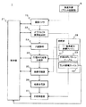
図2は、光学式外観検査装置1の機能的な構成を示すブロック図である。図2において、光学式外観検査装置1は、撮像カメラ15、制御部21、オブジェクト画像生成部22、穴認識部23、穴埋め円画像生成部24、画像収縮部25、画像合成部26、比較検査部27、記憶部28を備えている。
FIG. 2 is a block diagram showing a functional configuration of the optical
制御部21は、例えばCPUボードによって構成されている。制御部21は、以下に述べる各構成部と接続されている。また、制御部21は、ランド座標ファイルの読み込みや撮像カメラ15の動作制御や各種画像処理等の、本実施形態に係る検査処理全体の制御を行う。
The
オブジェクト画像生成部22は、撮像カメラ15が取り込んだ画像を2値化する。ここでは、撮像カメラ15が取り込んだ画像を構成する各画素のうち、所定の閾値より濃度が高い画素を1とし、残りの画素を0として2値化するものとする。もちろん、所定の閾値より濃度が高い画素を0とし、残りの画素を1としても構わない。そして、ランド部分の画像であるオブジェクト画像を生成し、穴認識部23へ出力する。ここで、当該オブジェクト画像の画素数は、以下に述べる穴埋め円画像の画素数と等しいものとする。更に、オブジェクト画像生成部22は、当該オブジェクト画像において値が1である画素(以下、1−画素と称す)の部分の座標を抽出した1−画素部分座標ファイル31を生成し、記憶部28に格納する。なお、図面では、1−画素を黒で、0−画素(値が0である画素)を白で表現している。
The object
穴認識部23は、オブジェクト画像に対して、放射状の測長子を用いてランドの穴(以下、スルーホール)の直径を測定する(図17参照)。そして、測定した直径を穴埋め円画像生成部24へ出力する。
The
穴埋め円画像生成部24は、穴埋め円パターンテーブル29を参照し、穴認識部23で測定したスルーホールの直径に応じた円画像(以下、穴埋め円画像)を読み出す。そして、読み出した穴埋め円画像292を画像収縮部25へ出力する。
The hole-filling circle
画像収縮部25は、所定の画像に対して8近傍収縮処理を行う。すなわち、2値化画像における1−画素と0−画素の境界において、1−画素を1層分細くさせる処理(収縮処理)であって、8近傍に1つでも0−画素があれば、その画素を0−画素とする処理を行う。また、画像収縮部25は、収縮した画像を画像合成部26へ出力する。
The
画像合成部26は、所定の画像とオブジェクト画像を合成して、合成画像を生成する。合成画像とは、比較検査部27がマスター画像302と比較検査するために用いる画像である。画像合成部26は、当該合成画像を比較検査部27へ出力する。
The
比較検査部27は、上記合成画像とランド座標ファイル30から読み出されるマスター画像302とを比較する。そして、一定以上の相違があれば、当該ランド部分には欠陥があると判定する。
The
記憶部28は、例えば半導体メモリやハードディスク等の記憶媒体であり、穴埋め円パターンテーブル29、ランド座標ファイル30および1−画素部分座標ファイル31、その他処理に必要となるデータが格納されている。
The
次に、本実施形態で用いられる各種データについて説明する。図3は、上記穴埋め円パターンテーブル29のデータ構造を示した図である。図3において、穴埋め円パターンテーブル29は、直径値291と穴埋め円画像292との組の集合から成る。直径値291は、上記穴認識部23が計測したスルーホールの直径に対応するものである。穴埋め円画像292は、当該スルーホールを有するランドより少し大きめになるような円の画像(2値化されている)である。例えば、図4に示すように、ランドの直径が1mmであり、スルーホールの直径が0.8mmの場合、直径0.8mmに対応する穴埋め円画像292として、直径1.2mmの円画像データが格納されている(図4参照)。また、当該穴埋め円画像292の画素数については、上記オブジェクト画像の画素数と一致するものである。
Next, various data used in the present embodiment will be described. FIG. 3 shows the data structure of the hole-filling circle pattern table 29. As shown in FIG. In FIG. 3, the hole-filling circle pattern table 29 includes a set of sets of a
図5は、ランド座標ファイル30のデータ構造を示した図である。図5に示すように、ランド座標ファイル30は、ランド座標301と当該ランドのマスター画像302との組の集合からなる。ランド座標301は、検査対象となるプリント基板上の各ランドの座標である。例えば、あらかじめCADデータ等から取得した各ランドの中心座標等が該当する。マスター画像302は、CADデータから作成されるランドの画像である。当該マスター画像302は、CADデータから作成されるため、穴が空いてない状態のランドの画像となっている。
FIG. 5 is a diagram showing the data structure of the land coordinate
図6は、1−画素部分座標ファイル31のデータ構造を示した図である。図6に示すように、1−画素部分座標ファイル31は、上記オブジェクト画像上において1−画素である画素の位置を示す1−画素座標311の集合からなる。
FIG. 6 is a diagram showing the data structure of the 1-pixel partial coordinate
次に、本実施形態に係る光学式外観検査装置1の動作概要を説明する。ここでは、図16(A)に示すようなランドの座切れを検出する場合を例として説明する。まず、制御部21は、上記ランド座標ファイル30に順次アクセスして、ランド座標301およびマスター画像302を読み出す。次に、読み出したランド座標へ撮像カメラ15を移動する。次に、ランド画像を撮像し、2値化した画像(以下、オブジェクト画像と称す)を生成する。併せて、オブジェクト画像において1−画素である座標を抽出し、1−画素部分座標ファイル31を生成する。次に、2値化した画像からスルーホールの直径を測定する。次に、当該直径に対応する穴埋め円画像292を穴埋め円パターンテーブル29から読み出す。次に、上記1−画素部分座標ファイル31と照らし合わせながら、上記穴埋め円画像292に対して所定の回数だけ8近傍収縮処理を行う。そして、当該収縮後の穴埋め円画像を、上記読み出したマスター画像302と比較することで、当該ランドの座切れの有無を検査する。この一連の処理を、検査対象がなくなるまで(ランド座標ファイル30の最後まで)繰り返すものである。
Next, an outline of the operation of the optical
以下、図7〜図10を用いて、光学式外観検査装置1が行うランドパターン検査処理の詳細動作を説明する。図7は、本発明の第1の実施形態にかかるランドパターン検査処理を示すフローチャートである。まず、制御部21は、ランド座標ファイル30からランド座標301およびマスター画像302を読み出す(ステップS1)。
Hereinafter, the detailed operation of the land pattern inspection process performed by the optical
次に、制御部21は、読み出したランド座標301に撮像カメラ15を移動させる。そして、制御部21は、撮像カメラ15でランド画像を撮像する(ステップS2)。
Next, the
ランド画像を撮像すれば、制御部21は、オブジェクト画像生成部22に、オブジェクト画像を生成させる(ステップS3)。ステップS3においては、オブジェクト画像生成部22は、撮像カメラ15が撮像したランド画像を2値化して、オブジェクト画像を生成する。更に、オブジェクト画像生成部22は、当該オブジェクト画像において、1−画素である部分の座標群を抽出し、当該座標群を格納した1−画素部分座標ファイル31を生成する。
When the land image is captured, the
次に、制御部21は、穴認識部23にスルーホールの直径を測定させる(ステップS4)。ステップS4においては、穴認識部23は、オブジェクト画像生成部22が生成したオブジェクト画像について、上述した従来技術と同様に、放射状の測長子を用いてスルーホールの直径を測定する(図17参照)。
Next, the
スルーホールの直径が測定できれば、次に制御部21は、穴埋め円画像生成部24に、穴埋め円画像292を生成させる(ステップS5)。ステップS5においては、穴埋め円画像生成部24は、上記測定した直径に基づいて、穴埋め円パターンテーブル29から穴埋め円画像292を検索し、読み出すことで穴埋め円画像292を生成する(ステップS5)。
If the diameter of the through hole can be measured, the
次に、穴埋め円画像292が生成できれば、次に、制御部21は、画像収縮部25にランド停止付き収縮処理を行わせる(ステップS6)。ステップS6では、穴埋め円画像292について8近傍収縮処理が行われるが、このとき、各画素(注目点)について収縮を行う前に、上記1−画素部分座標ファイル31を参照する。そして、注目点がオブジェクト画像における1−画素の座標と一致する(すなわち、ランドの部分)ときは、その注目点については収縮処理を行わないとする処理が行われる。
Next, if the hole-filled
図8は、上記ステップS6で示したランド停止付き収縮処理の詳細を示すフローチャートである。ここでは、穴埋め円画像の外周1周分の画素(以下、境界画素と称す)についての収縮処理(以下、周回処理と称す)が所定回数行われる。そして、当該周回処理が行われる回数については、少なくとも穴埋め円画像292の外周がオブジェクト画像上のスルーホール内に相当する位置に達するに必要十分な処理回数が予め定められている。すなわち、ランド停止付き収縮処理を行っている過程で穴埋め円画像の外周がランドの外周に達したときでも、ランドの座切れ部分については、更にアニュアリング(ランド径とドリルビット径の差)を越えて、穴埋め円画像292の外周がスルーホール内に達するような周回処理回数が予め定められている。以下、説明を分かりやすくするために、周回処理を10回行うものとして説明する。
FIG. 8 is a flowchart showing details of the contraction process with land stop shown in step S6. Here, a contraction process (hereinafter referred to as a rounding process) is performed a predetermined number of times for pixels (hereinafter referred to as boundary pixels) for one round of the outer periphery of the hole-filled circle image. With respect to the number of times that the rounding process is performed, the number of times necessary and sufficient for at least the outer circumference of the hole-filled
図8において、まず、画像収縮部25は、穴埋め円画像292の境界画素の座標群(以下、境界座標群)を抽出する(ステップS11)。次に、画像収縮部25は、抽出した境界座標群から、注目点とする画素の座標(以下、注目座標)を決定する(ステップS12)。次に、画像収縮部25は、注目座標の値を基として、1−画素部分座標ファイル31を検索する(ステップS13)。次に、画像収縮部25は、その検索結果を判定する(ステップS14)。その結果、注目座標と一致する座標が1−画素部分座標ファイル31に存在すれば、上記オブジェクト画像と上記穴埋め円画像292の画素数が一致していることから、当該注目座標は、上記オブジェクト画像上のランド部分に該当することとなる。そのため、画像収縮部25は、その注目座標については8近傍収縮処理を行わない。すなわち、ステップS14の判定の結果、一致する座標が存在しなければ(ステップS14でNO)、画像収縮部25は、当該注目座標について8近傍収縮処理を行う(ステップS15)。一方、一致する座標が存在すれば(ステップS14でYES)、画像収縮部25は、ステップS15の処理を行わず、処理をステップS16へ進める。
In FIG. 8, first, the
ステップS16においては、画像収縮部25は、上記境界座標群の全ての座標について上記ステップS12〜S15までの処理を行ったか否か、すなわち、1回分の周回処理が終了したか否かを判定する(ステップS16)。その結果、まだ1回分の周回処理が終了していないときは(ステップS16でNO)、画像収縮部25は、上記ステップS12に戻って処理を繰り返す。一方、1回分の周回処理が終わったときは、画像収縮部25は、処理を次のステップS17に進める。
In step S16, the
ステップS17においては、画像収縮部25は、指定された回数分、周回処理を行ったか否か、すなわち、周回処理を10回行ったか否かを判定する。その結果、周回処理を10回行っていなければ(ステップS17でNO)、画像収縮部25は、上記ステップS11に戻って処理を繰り返す。一方、周回処理を10回行っていれば(ステップS17でYES)、画像収縮部25は、当該ランド停止付き収縮処理を終了する。
In step S <b> 17, the
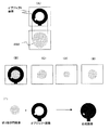
上記ランド停止付き収縮処理の流れにつき、図9を用いて補足説明する。まず、図9(A)は、ランド停止付き収縮処理開始前のオブジェクト画像および穴埋め円画像292を示す。両画像とも、画素数は同一であるとする。なお、オブジェクト画像のランド部分については、実際は上述した1−画素部分座標ファイル31にその座標が格納されているものであるが、ここでは説明をわかりやすくするため、オブジェクト画像のままで説明する。
The flow of the contraction process with the land stop will be supplementarily described with reference to FIG. First, FIG. 9A shows an object image and a hole-filled
次に、図9(B)は、1回目の周回処理の処理対象を示す図である。図9(B)下段で示すように、穴埋め円画像292の境界画素(外周に相当する部分の画素)が、周回処理の対象となっている。そして、当該境界画素について、8近傍収縮処理が行われる。その結果、当該境界画素に対応するオブジェクト画像の領域にはランド部分(1−画素)は存在しないため、当該境界領域の全てが0−画素に置き換わることになる。すなわち、穴埋め円画像292が一回り小さくなることになる。
Next, FIG. 9B is a diagram illustrating a processing target of the first round processing. As shown in the lower part of FIG. 9B, the boundary pixels (pixels corresponding to the outer periphery) of the hole-filled
次に、図9(C)は、4回目の周回処理終了時の状態を示す図である。図9(C)においては、境界画素すなわち穴埋め円画像の外周(図9(C)下段)と、ランド画像の外周(図9(C)上段)とが一致している状態を示している。すなわち、4回目の収縮で、穴埋め円とランドの径が一致したことを示している。 Next, FIG. 9C is a diagram showing a state at the end of the fourth round process. FIG. 9C shows a state in which the boundary pixel, that is, the outer periphery of the hole-filled circle image (the lower stage in FIG. 9C) and the outer periphery of the land image (the upper stage in FIG. 9C) match. That is, in the fourth contraction, the hole filling circle and the land have the same diameter.
次に、図9(D)は、5回目の周回処理開始時の状態を示す図である。5回目の周回処理以降においては、境界画素のうち、ランド部分に接している部分については、それ以上収縮が行われず、座切れの部分の画素Kのみが収縮することになる。その結果、図9(E)および(F)に示すように、座切れ部分Kのみが収縮していく。図9(E)は、6回目の収縮処理開始時の状態を示し、図9(F)は、8回目の収縮処理開始時の状態を示したものである。そして、最終的に10回まで周回処理が行われると、図9(G)に示すように、座切れ部分のみが収縮した状態の穴埋め円画像292ができることになる。なお、周回処理の回数について、アニュアリングを越えて穴埋め円画像292の外周がスルーホール内に達するような回数まで行っているため、スルーホール相当部分の一部についても収縮が行われる。その結果、座切れの部分がより際立った形となっている。
Next, FIG. 9D is a diagram showing a state at the start of the fifth round process. After the fifth rounding process, no further contraction is performed on the portion of the boundary pixel that is in contact with the land portion, and only the pixel K in the cut-off portion contracts. As a result, as shown in FIGS. 9E and 9F, only the cut-off portion K contracts. FIG. 9E shows a state at the start of the sixth contraction process, and FIG. 9F shows a state at the start of the eighth contraction process. Then, when the rounding process is finally performed up to 10 times, as shown in FIG. 9G, a hole-filled
図7に戻り、ステップS6の処理の次に、制御部21は、画像合成部26に合成画像を生成させる(ステップS7)。ステップS7においては、画像合成部26は、上記収縮処理後の穴埋め円画像292とオブジェクト画像とを合成することで、合成画像を生成する(図9(H))。
Returning to FIG. 7, after the process of step S6, the
次に、制御部21は、比較検査部27に、比較検査処理を行わせる(ステップS8)。ステップS8においては、比較検査部27は、図10に示すように、上記ステップS1で読み出したマスター画像302と上記合成画像とを比較する。その結果、所定の閾値以上の相違があれば、当該検査対象となっているランドには欠陥があると判定する。
Next, the
ステップS8の処理が終われば、制御部21は、ランド座標ファイル30を全て読み込んだか、すなわち、まだ検査対象となるランドが残っているか否かを判定する(ステップS9)。その結果、まだ検査対象のランドが残っている場合は(ステップS9でYES)、制御部21は、上記ステップS1に戻って処理を繰り返す。一方、検査対象のランドが残っていない場合は(ステップS9でNO)、制御部21は、当該ランドパターン検査処理を終了する。以上で、第1の実施形態に係るランドパターン検査処理は終了する。
When the process of step S8 is completed, the
このように、第1の実施形態では、ランドより大きい円画像を用意し、収縮処理を行うにあたって、2値化されたオブジェクト画像の1−画素部分に注目点が該当するか否かを判定しながら8近傍収縮していく。そして、当該円画像とオブジェクト画像を合成することで、スルーホールが埋まった状態のランドの画像を生成する。これをマスター画像302と比較することによって、従来の測長子を用いた検査方法では検出できなかった微細なランドの座切れも検出できる。また、当該微細な座切れを検出するために測長子の本数を増やすという必要もない。そのため、測長子が増えることによる演算処理の負荷、ひいては処理速度の低下を防止することができる。更に、測長子を増やす必要がないことから、ハードウェアにかかるコストを抑えながら、欠陥検出精度の高い検査装置を構成することも可能となる。
As described above, in the first embodiment, when a circular image larger than the land is prepared and the contraction process is performed, it is determined whether or not the attention point corresponds to the 1-pixel portion of the binarized object image. However, it contracts in the vicinity of 8. Then, by synthesizing the circle image and the object image, an image of the land with the through hole filled therein is generated. By comparing this with the
なお、上記実施形態における収縮処理では、8近傍収縮処理を用いていたが、これに限らず、4近傍収縮処理等を用いて収縮しても良い。また、上記ステップ5における穴埋め円画像の読み出しについて、穴埋め円パターンテーブル29の穴埋め円画像292の代りに、当該画像の直径値のみを格納しておき、画像についてはその都度、当該直径に基づいて円を生成し、2値化して穴埋め円画像を生成するようにしてもよい。これにより、記憶のために必要な容量が大きくなりがちな画像ファイルを記憶せずにすみ、記憶部28にかかる容量を節約してコストダウンを図ることも可能となる。
In the above-described embodiment, the 8-neighbor contraction process is used in the contraction process. However, the present invention is not limited to this, and a 4-neighbor contraction process or the like may be used. In addition, regarding the reading of the hole-filled circle image in the above step 5, instead of the hole-filled
(第2の実施形態)
次に、図11から図15を参照して、本発明の第2の実施形態について説明する。上述の第1の実施形態では、穴埋め円画像292のランド停止付き収縮処理が終わった後、収縮後の穴埋め円画像を用いて比較検査している。これに対して、第2の実施形態では、ランド停止付き収縮処理が終わった後、穴埋め円画像292をオブジェクト画像でマスキングして切り抜いた画像である切り抜き円画像を生成する。更に、当該切り抜き円画像に対して画像収縮→膨張処理を行う。その後、当該切り抜き円画像とオブジェクト画像を合成することにより、合成画像を生成する。そして、当該合成画像とマスター画像302とを比較検査するものである。なお、当該実施形態に係る光学式外観検査装置40は、上述した第1の実施形態で図2を用いて説明した光学式外観検査装置1の機能構成に切り抜き円画像生成部41および画像膨張部42を加えたものに相当し、他の構成部は、第1の実施形態と同様である。従って、切り抜き円画像生成部41および画像膨張部42以外の構成部については同一の参照符号を付して詳細な説明を省略する。
(Second Embodiment)
Next, a second embodiment of the present invention will be described with reference to FIGS. In the first embodiment described above, after the shrink process with land stop of the hole-filled
図11は、本発明の第2の実施形態に係る光学式外観検査装置40の構成を示したブロック図である。図11において、切り抜き円画像生成部41は、収縮処理後の穴埋め円画像292にオブジェクト画像をマスキングして、穴埋め円画像292を切り抜く。いわば型抜きの要領でスルーホールに相当する切り抜き円画像を生成するものである。なお、当該切り抜き円画像は2値化されて生成される。画像膨張部42は、8近傍膨張処理を行うことで、所定の画像を膨張させる。すなわち、2値化画像における1−画素と0−画素の境界において、1−画素を1層分厚くさせる処理(膨張処理)であって、8近傍に1つでも1−画素があれば、その画素を1−画素とする処理を行う。また、画像膨張部42は、膨張後の画像を画像合成部26へ出力する。
FIG. 11 is a block diagram showing a configuration of an optical
以下、図12〜図15を用いて、本発明の第2の実施形態にかかるランドパターン検査処理の詳細を説明する。ここでは、図16(B)に示すようなランド欠損を検出する場合を例とする。図12は、第2の実施形態にかかる光学式外観検査装置40が行うランド欠陥検出処理を示すフローチャートである。図12において、ステップS21からステップS25までの処理は、上述の第1の実施形態で図7を用いて説明したステップS1からステップS5の処理と同様であるため、ここでは詳細な説明を省略する。また、ステップS31からステップS32までの処理についても、上述の第1の実施形態で図7を用いて説明したステップS8からステップS9の処理と同様であるため、ここでは詳細な説明を省略する。
The details of the land pattern inspection process according to the second embodiment of the present invention will be described below with reference to FIGS. Here, a case where a land defect as shown in FIG. 16B is detected is taken as an example. FIG. 12 is a flowchart illustrating land defect detection processing performed by the optical
次に、ステップS26〜S30の処理について、図12〜図14を用いて説明する。図13は、ステップS26〜S30における穴埋め円画像および切り抜き円画像の変化を示す図である。また、図14は、ステップS28およびS29における切り抜き円画像の変化を示す図である。まず、制御部21は、画像収縮部25に穴埋め円画像292のランド停止付き収縮処理を行わせる(ステップS26)。ステップS26において、画像収縮部25は、上述の第1の実施形態で図7を用いて説明したステップS6の処理と同様に、穴埋め円画像292に対してランド停止付き収縮処理を行う。その結果、例えば、4回目の収縮で、穴埋め円画像292がランドの径と同じ大きさになったとする(図13(A))。ここで、本実施形態におけるランドの欠損は、ランドの内周部にあり、外周については欠けている部分がない。そのため、引き続いて収縮を行っても、穴埋め円画像292は4回目の状態から収縮しないことになる。その結果、ステップS26におけるランド停止付き収縮処理が終了した時点でも、穴埋め円画像292の大きさはランドの外周円と同じ大きさ(図13(A))となっている。
Next, the process of steps S26 to S30 will be described with reference to FIGS. FIG. 13 is a diagram illustrating changes in the hole-filling circle image and the cutout circle image in steps S26 to S30. FIG. 14 is a diagram showing changes in the cutout circle image in steps S28 and S29. First, the
次に、制御部21は、切り抜き円画像生成部41に、切り抜き円画像生成処理を行わせる(ステップS27)。ステップS27においては、切り抜き円画像生成部41は、穴埋め円画像292にオブジェクト画像をマスキングして(図13(B))穴埋め円画像292を切り抜くことで、切り抜き円画像(図13(C))を生成する。その結果、当該切り抜き円画像は、スルーホールに対し、ランドの欠損部分が「突起」として存在するような画像となる。
Next, the
次に、制御部21は、上記突起を取り除くべく、収縮→膨張処理を行う(ステップS28、S29)。ここで行われる収縮処理は、上記ステップS26で行われるランド停止付き収縮処理と異なり、1−画素部分座標ファイル31を用いずに行われるものである。すなわち、上記切り抜き円画像の「突起」を消去するための処理であるため、単純に切り抜き円画像自身の1−画素、0−画素を判定して8近傍収縮処理を行うものである(以下、ランド停止付き収縮処理と区別するため、均等収縮処理と称す)。
Next, the
ステップS28においては、画像収縮部25は、所定の回数、例えば1回だけ均等収縮処理を切り抜き円画像に対して行う。図14において、まず、図14(A)が収縮前の切り抜き円画像を示している(「□」が1−画素に相当する)。図14(A)では、ランド欠損部に相当する部分の画素141(突起)が存在している(図13の(C)に相当)。この画像に対し、8近傍収縮を行うと、図14(B)に示すように、周囲8画素が1−画素である、「・」のついている画素のみが残ることになる(図13の(D)に相当)。以上で、ステップS28における処理は終了する。
In step S <b> 28, the
次に、ステップS29において、画像膨張部42は、ステップS28で均等収縮した切り抜き円画像(図14(B))に対して、ステップS28で収縮した回数だけ膨張処理を行う。すなわち、上記ステップS28では1回だけ均等収縮処理を行ったので、ここでは、1回だけ膨張処理を行う。その結果、図14(C)に示すように、ランド欠損部の相当する「突起」が消去された切り抜き円画像となる(図13の(E)に相当)。また、ステップS28における収縮回数とステップS29における膨張回数とを等しくしているため、切り抜き円画像が元の大きさに戻ることになる。その結果、スルーホールのみを隙間無く埋める画像ができることとなる。
Next, in step S29, the
図12に戻り、次に、制御部21は、画像合成部26に合成画像を生成させる(ステップS30)。ステップS30においては、画像合成部26は、図13(F)に示すように、上記膨張処理後の切り抜き円画像とオブジェクト画像とを合成することで、合成画像を生成する。
Returning to FIG. 12, next, the
以上のように、穴埋め円画像から切り抜き円画像を切り抜き、一旦均等収縮処理を行ってから膨張処理を行うことで、ランドの内円と同じ大きさの画像が得られる。そして、これを用いて合成画像を生成し、図15に示すようにマスター画像302と比較すれば(ステップS31)、ランド欠損を検出することが可能となる。以上で、第2の実施形態に係るランドパターン検査処理が終了する。
As described above, an image having the same size as the inner circle of the land can be obtained by cutting out the cutout circle image from the hole-filled circle image, performing the uniform shrinkage process, and then performing the expansion process. Then, a composite image is generated using this, and compared with the
このように、第2の実施形態では、穴埋め円画像をオブジェクト画像で切り抜き、一旦均等収縮してから膨張することにより、ランド欠損部に相当する画像の雑音(突起)を消去することができる。そして、この画像とオブジェクト画像を合成すれば、スルーホールのみが埋まったランド画像を生成でき、当該画像とマスター画像302を比較検査すれば、第1の実施形態では検出できないような欠陥も検出できる。すなわち、第1の実施形態においては、ランドの外周に切れ目があるような欠陥(ランド座切れ:図16(A))は検出できるが、ランドの外周に切れ目がないような欠陥(ランド欠損:図16(B))は検出できない。一方、第2の実施形態によれば、ランド座切れに加え、ランド欠損についても検出することができる。その結果、ランド欠陥検出の精度を更に上げることが可能となる。
As described above, in the second embodiment, noise (protrusions) in the image corresponding to the land defect portion can be eliminated by cutting out the hole-filled circle image with the object image, and once expanding it after uniform shrinkage. Then, if this image is combined with the object image, a land image in which only the through hole is filled can be generated, and if the image is compared with the
なお、本発明にかかる検査方法については、従来行われていた測長子検査に続いて行うことが望ましい。すなわち、測長子検査によりランドの座切れが見つかれば、本工程は回避し、測長子検査で異常が発見されなかったときに本発明による検査方法を実施することが望ましい。 In addition, about the inspection method concerning this invention, it is desirable to carry out following the length measuring inspection performed conventionally. That is, it is desirable to avoid this step if a land break is found by the length sensor inspection, and to carry out the inspection method according to the present invention when no abnormality is found by the length measurement inspection.
また、上記実施形態では、ランドパターン形状の検査に特化して、ランド座標に基づいて順次対象となるランドを撮像し、かつ検査をするように説明をしているが、基板上のパターン全部の比較検査において同時にランドパターンの検査を行うようにしてもよい。すなわち、予め全ての基板画像を読み取っておき、対象となるランド座標近傍のオブジェクト画像を本発明による画像処理によってランド座切れやランド欠損が判別可能なように穴埋めされたオブジェクト画像に変換しておき、ランドを含む全てのパターンの比較検査を行うようにしてもよい。また、上記の場合、比較の対象となるマスター画像については、CADなどの設計データではなくて良品基板を撮像して得た画像を用いてもよい。 Moreover, in the said embodiment, it is specialized to inspect the land pattern shape, and it has been described that the target lands are sequentially imaged and inspected based on the land coordinates, but the entire pattern on the substrate is inspected. The land pattern may be inspected simultaneously in the comparative inspection. That is, all the substrate images are read in advance, and the object image near the target land coordinates is converted into an object image that is filled in so that a land cutout or a land defect can be identified by image processing according to the present invention, You may make it perform the comparative test | inspection of all the patterns containing a land. In the above case, as a master image to be compared, an image obtained by imaging a non-defective substrate may be used instead of design data such as CAD.
本発明にかかるランドパターン検査方法およびランドパターン検査装置は、測長子を用いる方法では検出できないような微細なランド欠陥を検出することができ、プリント基板検査装置等の用途に有用である。 INDUSTRIAL APPLICABILITY The land pattern inspection method and land pattern inspection apparatus according to the present invention can detect fine land defects that cannot be detected by a method using a length measuring element, and are useful for applications such as a printed circuit board inspection apparatus.
1、40 光学式外観検査装置
11 ステージ部
12 ステージ支持部
13 ステージ駆動機構
14 ベース部
15 撮像カメラ
16 支持部材
17 カメラ支持部
18 カメラ駆動機構
21 制御部
22 オブジェクト画像生成部
23 穴認識部
24 穴埋め円画像生成部
25 画像収縮部
26 画像合成部
27 比較検査部
28 記憶部
29 穴埋め円パターンテーブル
30 ランド座標ファイル
31 1−画素部分座標ファイル
41 切り抜き円画像生成部
42 画像膨張部
121 ランド欠損部に相当する部分の画素
151 測長子
291 直径値
292 穴埋め円画像
301 ランド座標
302 マスター画像
311 1−画素座標
DESCRIPTION OF
Claims (8)
前記被検査物に形成されたランドパターンを撮像して得られる画像を2値化したオブジェクト画像を作成するオブジェクト画像作成ステップと、
前記オブジェクト画像からランドパターンに形成されているスルーホールの直径を計測する穴認識ステップと、
前記計測した直径に基づき、前記ランドパターンのランド径より大きな円の画像である穴埋め円画像を生成する穴埋め円画像生成ステップと、
前記穴埋め円画像に対して、収縮処理を予め定められた回数以上繰り返して実行する穴埋め円画像収縮ステップと、
前記収縮後の穴埋め円画像と前記オブジェクト画像を合成して合成画像を生成する合成画像生成ステップと、
前記マスター画像と前記合成画像とを比較して、当該被検査物のランドのパターン形状を検査するランドパターン検査ステップとを有し、
前記穴埋め円画像収縮ステップにおいて、同一の座標軸上で前記オブジェクト画像と前記穴埋め円画像との位置合わせを行い、前記収縮の対象となる画素である注目点が前記オブジェクト画像におけるランド部分と対応していると判断されたときは、当該注目点については前記収縮を行わないことを特徴とする、ランドパターン検査方法。 A land pattern inspection method for inspecting a land pattern shape of an inspection object by comparing an object image obtained by imaging a land pattern formed on the inspection object with a master image of the land pattern,
An object image creation step for creating an object image obtained by binarizing an image obtained by imaging a land pattern formed on the inspection object;
A hole recognition step of measuring the diameter of the through hole formed in the land pattern from the object image;
Based on the measured diameter, a filling circle image generating step for generating a filling circle image that is an image of a circle larger than the land diameter of the land pattern;
A hole-filling circle image shrinking step for repeatedly executing shrinkage processing for a predetermined number of times for the hole-filling circle image;
A combined image generation step of generating a combined image by combining the object image and the hole-filled circle image after contraction;
A land pattern inspection step for comparing the master image with the composite image and inspecting a land pattern shape of the inspection object;
In the hole-filling circle image shrinking step, the object image and the hole-filling circle image are aligned on the same coordinate axis, and a target point that is a pixel to be shrunk corresponds to a land portion in the object image. The land pattern inspection method according to claim 1, wherein the contraction is not performed on the attention point when it is determined that the target point is present.
前記被検査物に形成されたランドパターンを撮像して得られる画像を2値化したオブジェクト画像を作成するオブジェクト画像作成ステップと、
前記オブジェクト画像からランドパターンに形成されているスルーホールの直径を計測する穴認識ステップと、
前記計測した直径に基づき、前記ランドパターンのランド径より大きな円の画像である穴埋め円画像を生成する穴埋め円画像生成ステップと、
前記穴埋め円画像に対して、収縮処理を予め定められた回数以上繰り返して実行する穴埋め円画像収縮ステップと、
前記穴埋め円画像収縮ステップにより収縮された穴埋め円画像をオブジェクト画像でマスキングし、当該穴埋め円画像から当該オブジェクト画像のランド部分に対応する領域を切り抜くことで切り抜き円画像を生成する切り抜き円画像生成ステップと、
前記切り抜き円画像を所定の回数だけ収縮し、その後、当該所定の回数だけ膨張する切り抜き円画像収縮膨張ステップと、
前記膨張後の切り抜き円画像と前記オブジェクト画像を合成することで合成画像を生成する合成画像生成ステップと、
前記マスター画像と前記合成画像とを比較して、当該被検査物のランドのパターン形状を検査するランドパターン検査ステップとを有し、
前記穴埋め円画像収縮ステップにおいて、同一の座標軸上で前記オブジェクト画像と前記穴埋め円画像との位置合わせを行い、前記収縮の対象となる画素である注目点が前記オブジェクト画像におけるランド部分と対応していると判断されたときは、当該注目点については前記収縮を行わないことを特徴とする、ランドパターン検査方法。 A land pattern inspection method for inspecting a land pattern shape of an inspection object by comparing an object image obtained by imaging a land pattern formed on the inspection object with a master image of the land pattern,
An object image creation step for creating an object image obtained by binarizing an image obtained by imaging a land pattern formed on the inspection object;
A hole recognition step of measuring the diameter of the through hole formed in the land pattern from the object image;
Based on the measured diameter, a filling circle image generating step for generating a filling circle image that is an image of a circle larger than the land diameter of the land pattern;
A hole-filling circle image shrinking step for repeatedly executing shrinkage processing for a predetermined number of times for the hole-filling circle image;
A cutout circle image generation step of masking the hole-filled circle image shrunk in the hole-filling circle image shrinking step with an object image and generating a cutout circle image by cutting out a region corresponding to the land portion of the object image from the hole-filled circle image. When,
A cutout circle image shrinking and expanding step of shrinking the cutout circle image a predetermined number of times and then expanding the predetermined number of times;
A combined image generation step of generating a combined image by combining the clipped circle image after expansion and the object image;
A land pattern inspection step for comparing the master image with the composite image and inspecting a land pattern shape of the inspection object;
In the hole-filling circle image shrinking step, the object image and the hole-filling circle image are aligned on the same coordinate axis, and a target point that is a pixel to be shrunk corresponds to a land portion in the object image. The land pattern inspection method according to claim 1, wherein the contraction is not performed on the attention point when it is determined that the target point is present.
被検査物のランドパターンの画像を撮像する撮像部と、
前記ランドパターンのマスター画像を記憶する記憶部と、
前記撮像部が撮像した画像を2値化したオブジェクト画像を作成するオブジェクト画像作成部と、
前記オブジェクト画像からランドパターンに形成されているスルーホールの直径を計測する穴認識部と、
前記計測した直径に基づき、前記ランドパターンのランド径より大きな円の画像である穴埋め円画像を生成する穴埋め円画像生成部と、
前記穴埋め円画像に対して、収縮処理を予め定められた回数以上繰り返して実行する穴埋め円画像収縮部と、
前記収縮後の穴埋め円画像と前記オブジェクト画像を合成して合成画像を生成する合成画像生成部と、
前記記憶部から読み出したマスター画像と前記合成画像とを比較して、当該被検査物のランドのパターン形状を検査するランドパターン検査部とを有し、
前記穴埋め円画像収縮部において、同一の座標軸上で前記オブジェクト画像と前記穴埋め円画像との位置合わせを行い、前記収縮の対象となる画素である注目点が前記オブジェクト画像におけるランド部分と対応していると判断されたときは、当該注目点については前記収縮を行わないことを特徴とする、ランドパターン検査装置。 A land pattern inspection apparatus for inspecting a land pattern shape of an inspection object,
An imaging unit that captures an image of a land pattern of the inspection object;
A storage unit for storing a master image of the land pattern;
An object image creation unit that creates an object image obtained by binarizing the image captured by the imaging unit;
A hole recognition unit that measures the diameter of the through hole formed in the land pattern from the object image;
Based on the measured diameter, a hole-filling circle image generation unit that generates a hole-filling circle image that is an image of a circle larger than the land diameter of the land pattern;
For the hole-filled circle image, a hole-filling circle image shrinking unit that repeatedly executes shrinkage processing more than a predetermined number of times,
A composite image generation unit that generates a composite image by combining the object image and the hole-filled circle image after contraction;
Comparing the master image read from the storage unit and the composite image, and having a land pattern inspection unit that inspects the pattern shape of the land of the inspection object,
In the hole-filling circle image contraction unit, the object image and the hole-filling circle image are aligned on the same coordinate axis, and a point of interest that is a pixel to be contracted corresponds to a land portion in the object image. When it is determined that there is a land pattern inspection apparatus, the contraction is not performed on the attention point.
被検査物のランドパターン撮像を撮像する撮像部と、
前記ランドパターンのマスター画像を記憶する記憶部と、
前記撮像部が撮像した画像を2値化したオブジェクト画像を作成するオブジェクト画像作成部と、
前記オブジェクト画像からランドパターンに形成されているスルーホールの直径を計測する穴認識部と、
前記計測した直径に基づき、前記ランドパターンのランド径より大きな円の画像である穴埋め円画像を生成する穴埋め円画像生成部と、
前記穴埋め円画像に対して、収縮処理を予め定められた回数以上繰り返して実行する穴埋め円画像収縮部と、
前記穴埋め円画像収縮部により収縮された穴埋め円画像をオブジェクト画像でマスキングし、当該穴埋め円画像から当該オブジェクト画像のランド部分に対応する領域を切り抜くことで切り抜き円画像を生成する切り抜き円画像生成部と、
前記切り抜き円画像を所定の回数だけ収縮し、その後、当該所定の回数だけ膨張する切り抜き円画像収縮膨張部と、
前記膨張後の切り抜き円画像と前記オブジェクト画像を合成することで合成画像を生成する合成画像生成部と、
前記記憶部から読み出したマスター画像と前記合成画像とを比較して、当該被検査物のランドのパターン形状を検査するランドパターン検査部とを有し、
前記穴埋め円画像収縮部において、同一の座標軸上で前記オブジェクト画像と前記穴埋め円画像との位置合わせを行い、前記収縮の対象となる画素である注目点が前記オブジェクト画像におけるランド部分と対応していると判断されたときは、当該注目点については前記収縮を行わないことを特徴とする、ランドパターン検査装置。 A land pattern inspection apparatus for inspecting a land pattern shape of an inspection object,
An imaging unit for imaging a land pattern of the object to be inspected;
A storage unit for storing a master image of the land pattern;
An object image creation unit that creates an object image obtained by binarizing the image captured by the imaging unit;
A hole recognition unit that measures the diameter of the through hole formed in the land pattern from the object image;
Based on the measured diameter, a hole-filling circle image generation unit that generates a hole-filling circle image that is an image of a circle larger than the land diameter of the land pattern;
For the hole-filled circle image, a hole-filling circle image shrinking unit that repeatedly executes shrinkage processing more than a predetermined number of times,
A cutout circle image generating unit that masks the hole-filled circle image shrunk by the hole-filled circle image shrinking unit with an object image and generates a cutout circle image by cutting out a region corresponding to the land portion of the object image from the hole-filled circle image. When,
A cutout circle image shrinking and expanding portion that shrinks the cutout circle image a predetermined number of times and then expands the predetermined number of times;
A combined image generating unit that generates a combined image by combining the clipped circle image after expansion and the object image;
Comparing the master image read from the storage unit and the composite image, and having a land pattern inspection unit that inspects the pattern shape of the land of the inspection object,
In the hole-filling circle image contraction unit, the object image and the hole-filling circle image are aligned on the same coordinate axis, and a point of interest that is a pixel to be contracted corresponds to a land portion in the object image. When it is determined that there is a land pattern inspection apparatus, the contraction is not performed on the attention point.
Priority Applications (4)
| Application Number | Priority Date | Filing Date | Title |
|---|---|---|---|
| JP2005091990A JP4518494B2 (en) | 2005-03-28 | 2005-03-28 | Land pattern inspection method and inspection apparatus |
| TW094145474A TWI271505B (en) | 2005-03-28 | 2005-12-21 | Method for examining land pattern and apparatus for examining the same |
| CNB200610005927XA CN100507530C (en) | 2005-03-28 | 2006-01-19 | Welding disk pattern inspection method and inspection device |
| KR1020060006935A KR100660400B1 (en) | 2005-03-28 | 2006-01-23 | Land pattern inspection method and apparatus therefor |
Applications Claiming Priority (1)
| Application Number | Priority Date | Filing Date | Title |
|---|---|---|---|
| JP2005091990A JP4518494B2 (en) | 2005-03-28 | 2005-03-28 | Land pattern inspection method and inspection apparatus |
Publications (3)
| Publication Number | Publication Date |
|---|---|
| JP2006275612A JP2006275612A (en) | 2006-10-12 |
| JP2006275612A5 JP2006275612A5 (en) | 2008-03-06 |
| JP4518494B2 true JP4518494B2 (en) | 2010-08-04 |
Family
ID=37030156
Family Applications (1)
| Application Number | Title | Priority Date | Filing Date |
|---|---|---|---|
| JP2005091990A Expired - Fee Related JP4518494B2 (en) | 2005-03-28 | 2005-03-28 | Land pattern inspection method and inspection apparatus |
Country Status (4)
| Country | Link |
|---|---|
| JP (1) | JP4518494B2 (en) |
| KR (1) | KR100660400B1 (en) |
| CN (1) | CN100507530C (en) |
| TW (1) | TWI271505B (en) |
Families Citing this family (9)
| Publication number | Priority date | Publication date | Assignee | Title |
|---|---|---|---|---|
| JP5234639B2 (en) * | 2009-01-31 | 2013-07-10 | 株式会社メガトレード | Through-hole inspection equipment |
| CN101995223B (en) * | 2009-08-25 | 2013-05-08 | 比亚迪股份有限公司 | Chip appearance detection method and system |
| CN102595024B (en) * | 2011-12-16 | 2014-10-22 | 飞狐信息技术(天津)有限公司 | Method and device for restoring digital video images |
| CN104020222B (en) * | 2014-06-18 | 2016-06-22 | 长春光华微电子设备工程中心有限公司 | Fully-automatic supersonic aluminum wire press welder weld quality prediction system |
| CN104535587A (en) * | 2014-12-23 | 2015-04-22 | 安徽科鸣三维科技有限公司 | PCBA solder joint inspection method based on machine vision |
| JP6496159B2 (en) * | 2015-02-23 | 2019-04-03 | 株式会社Screenホールディングス | Pattern inspection apparatus and pattern inspection method |
| TWI521476B (en) * | 2015-04-17 | 2016-02-11 | 銘傳大學 | Automatic optical inspection method of periodic patterns |
| CN106651989B (en) * | 2016-12-21 | 2020-04-21 | 北京信息科技大学 | Nested circle fitting method and device for micro-hole centering |
| CN109950165B (en) * | 2019-02-19 | 2021-06-04 | 长江存储科技有限责任公司 | Test structure and test method |
Citations (2)
| Publication number | Priority date | Publication date | Assignee | Title |
|---|---|---|---|---|
| JPH01269035A (en) * | 1988-04-21 | 1989-10-26 | Ibiden Co Ltd | Instrument for inspecting printed circuit board |
| JP2001267722A (en) * | 2000-03-23 | 2001-09-28 | Ngk Spark Plug Co Ltd | Method for inspecting printed wiring board |
Family Cites Families (1)
| Publication number | Priority date | Publication date | Assignee | Title |
|---|---|---|---|---|
| JP3589424B1 (en) * | 2003-12-22 | 2004-11-17 | 株式会社メガトレード | Board inspection equipment |
-
2005
- 2005-03-28 JP JP2005091990A patent/JP4518494B2/en not_active Expired - Fee Related
- 2005-12-21 TW TW094145474A patent/TWI271505B/en not_active IP Right Cessation
-
2006
- 2006-01-19 CN CNB200610005927XA patent/CN100507530C/en not_active Expired - Fee Related
- 2006-01-23 KR KR1020060006935A patent/KR100660400B1/en not_active IP Right Cessation
Patent Citations (2)
| Publication number | Priority date | Publication date | Assignee | Title |
|---|---|---|---|---|
| JPH01269035A (en) * | 1988-04-21 | 1989-10-26 | Ibiden Co Ltd | Instrument for inspecting printed circuit board |
| JP2001267722A (en) * | 2000-03-23 | 2001-09-28 | Ngk Spark Plug Co Ltd | Method for inspecting printed wiring board |
Also Published As
| Publication number | Publication date |
|---|---|
| CN1841049A (en) | 2006-10-04 |
| JP2006275612A (en) | 2006-10-12 |
| CN100507530C (en) | 2009-07-01 |
| TW200636207A (en) | 2006-10-16 |
| KR20060103823A (en) | 2006-10-04 |
| TWI271505B (en) | 2007-01-21 |
| KR100660400B1 (en) | 2006-12-22 |
Similar Documents
| Publication | Publication Date | Title |
|---|---|---|
| JP4518494B2 (en) | Land pattern inspection method and inspection apparatus | |
| KR100689792B1 (en) | Apparatus and method for detecting defect and apparatus and method for extracting wire area | |
| US20060018534A1 (en) | Technique for detecting a defect of an object by area segmentation of a color image of the object | |
| KR960013357B1 (en) | Image data inspecting method and apparatus | |
| JP2008047664A (en) | Pattern inspecting apparatus and semiconductor inspecting system | |
| JP4230880B2 (en) | Defect inspection method | |
| KR20070062905A (en) | Differential comparison inspection method and apparatus thereof | |
| JP2011007728A (en) | Method, apparatus and program for defect detection | |
| JP4982125B2 (en) | Defect inspection method and pattern extraction method | |
| JP2002042112A (en) | Part mounting inspecting method for circuit board and its system | |
| JP3575512B2 (en) | Pattern inspection method and apparatus | |
| JP7068897B2 (en) | Inspection equipment and inspection method | |
| KR101630078B1 (en) | Data calculation method, data calculation apparatus, and defect inspection apparatus | |
| JP2006234554A (en) | Method and device for inspecting pattern | |
| JPS6147362B2 (en) | ||
| JP2500758B2 (en) | Printed circuit board pattern inspection device | |
| JPH08110305A (en) | Method and device for inspecting appearance | |
| JP2003203218A (en) | Visual inspection device and method | |
| JP3116438B2 (en) | Inspection apparatus and inspection method for printed wiring board | |
| JP2002198406A (en) | Appearance inspecting method | |
| JP4970101B2 (en) | Defect detection method | |
| JP7285988B2 (en) | Inspection device and inspection method | |
| JPH0723845B2 (en) | Defect detection method | |
| JP5096940B2 (en) | Inspection method and apparatus for printed wiring board | |
| JP2676990B2 (en) | Wiring pattern inspection equipment |
Legal Events
| Date | Code | Title | Description |
|---|---|---|---|
| A621 | Written request for application examination |
Free format text: JAPANESE INTERMEDIATE CODE: A621 Effective date: 20071218 |
|
| A521 | Request for written amendment filed |
Free format text: JAPANESE INTERMEDIATE CODE: A523 Effective date: 20080116 |
|
| A977 | Report on retrieval |
Free format text: JAPANESE INTERMEDIATE CODE: A971007 Effective date: 20100512 |
|
| TRDD | Decision of grant or rejection written | ||
| A01 | Written decision to grant a patent or to grant a registration (utility model) |
Free format text: JAPANESE INTERMEDIATE CODE: A01 Effective date: 20100514 |
|
| A01 | Written decision to grant a patent or to grant a registration (utility model) |
Free format text: JAPANESE INTERMEDIATE CODE: A01 |
|
| A61 | First payment of annual fees (during grant procedure) |
Free format text: JAPANESE INTERMEDIATE CODE: A61 Effective date: 20100514 |
|
| FPAY | Renewal fee payment (event date is renewal date of database) |
Free format text: PAYMENT UNTIL: 20130528 Year of fee payment: 3 |
|
| R150 | Certificate of patent or registration of utility model |
Ref document number: 4518494 Country of ref document: JP Free format text: JAPANESE INTERMEDIATE CODE: R150 |
|
| FPAY | Renewal fee payment (event date is renewal date of database) |
Free format text: PAYMENT UNTIL: 20130528 Year of fee payment: 3 |
|
| FPAY | Renewal fee payment (event date is renewal date of database) |
Free format text: PAYMENT UNTIL: 20130528 Year of fee payment: 3 |
|
| FPAY | Renewal fee payment (event date is renewal date of database) |
Free format text: PAYMENT UNTIL: 20140528 Year of fee payment: 4 |
|
| R250 | Receipt of annual fees |
Free format text: JAPANESE INTERMEDIATE CODE: R250 |
|
| R250 | Receipt of annual fees |
Free format text: JAPANESE INTERMEDIATE CODE: R250 |
|
| S533 | Written request for registration of change of name |
Free format text: JAPANESE INTERMEDIATE CODE: R313533 |
|
| R350 | Written notification of registration of transfer |
Free format text: JAPANESE INTERMEDIATE CODE: R350 |
|
| R250 | Receipt of annual fees |
Free format text: JAPANESE INTERMEDIATE CODE: R250 |
|
| R250 | Receipt of annual fees |
Free format text: JAPANESE INTERMEDIATE CODE: R250 |
|
| R250 | Receipt of annual fees |
Free format text: JAPANESE INTERMEDIATE CODE: R250 |
|
| R250 | Receipt of annual fees |
Free format text: JAPANESE INTERMEDIATE CODE: R250 |
|
| R250 | Receipt of annual fees |
Free format text: JAPANESE INTERMEDIATE CODE: R250 |
|
| R250 | Receipt of annual fees |
Free format text: JAPANESE INTERMEDIATE CODE: R250 |
|
| R250 | Receipt of annual fees |
Free format text: JAPANESE INTERMEDIATE CODE: R250 |
|
| LAPS | Cancellation because of no payment of annual fees |