JP4489979B2 - Ball stitching device - Google Patents
Ball stitching device Download PDFInfo
- Publication number
- JP4489979B2 JP4489979B2 JP2001006169A JP2001006169A JP4489979B2 JP 4489979 B2 JP4489979 B2 JP 4489979B2 JP 2001006169 A JP2001006169 A JP 2001006169A JP 2001006169 A JP2001006169 A JP 2001006169A JP 4489979 B2 JP4489979 B2 JP 4489979B2
- Authority
- JP
- Japan
- Prior art keywords
- cloth
- ball
- knife
- cutting
- sewing
- Prior art date
- Legal status (The legal status is an assumption and is not a legal conclusion. Google has not performed a legal analysis and makes no representation as to the accuracy of the status listed.)
- Expired - Fee Related
Links
Images


Classifications
-
- D—TEXTILES; PAPER
- D05—SEWING; EMBROIDERING; TUFTING
- D05B—SEWING
- D05B3/00—Sewing apparatus or machines with mechanism for lateral movement of the needle or the work or both for making ornamental pattern seams, for sewing buttonholes, for reinforcing openings, or for fastening articles, e.g. buttons, by sewing
- D05B3/10—Sewing apparatus or machines with mechanism for lateral movement of the needle or the work or both for making ornamental pattern seams, for sewing buttonholes, for reinforcing openings, or for fastening articles, e.g. buttons, by sewing for making piped openings
-
- D—TEXTILES; PAPER
- D05—SEWING; EMBROIDERING; TUFTING
- D05B—SEWING
- D05B37/00—Devices incorporated in sewing machines for slitting, grooving, or cutting
- D05B37/04—Cutting devices
Description
【0001】
【発明の属する技術分野】
本発明は、身生地と身生地上に供給された玉布とにより構成される玉縁布に、所望の縫製工程を経て玉縁縫いを施す玉縁縫い装置に関する。
【0002】
【従来の技術】
ポケットの開口部に対して図9(a)に示すような玉縁縫いと呼ばれる縫製が行われている。
【0003】
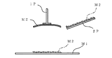
玉縁縫いの形成は、両側縁部を内側上方に折り曲げた(逆T字形状)玉布M2を身生地M1上に2本の平行な縫い目S,Sによって縫い合わせると同時に、センターメスにより2本の縫い目S,Sの中間に縫い目線に沿い且つ該縫い目S,Sよりも短いポケット孔Hを開け、その後、V字状のコーナーメスによりポケット孔Hの両端からそれぞれ縫い目S,S端へと延びるようにコーナーカット部C,Cを開けるようにして行われている。
【0004】
縫製終了後に玉布M2をポケット孔H内を通して1回転返すと図9(b)のような状態となり、玉縁が完成する。
【0005】
通常、玉縁縫い後、玉布2の折り目を整えるために身生地M1の裏面側からアイロンをかけるが、図10(a),(b)に示すように、玉布M2の両端部分は、布が幾重にも重なった状態にあるため、この状態でアイロンをかけた場合、身生地M1表面に前記折り重ね跡が現れて、縫製品の商品価値を低減するという問題があった。
【0006】
このような問題を回避するため、玉縁縫いを行う前に、ポケット孔Hの延長線上で、ポケット孔H両端から玉布M2両端まで切断して両端切断部位h,hを形成する方法が知られている。このように、両端切断部位h,hを形成すると、重なっていた玉布M2の両端部を、図10(C)に示すように外側に開くことができ、玉布M2の両端部分が厚くならないので上記問題を解決することができる。
【0007】
玉布M2の両端切断部位を切断する装置として本出願人は、特願平11−34684号を出願している。この装置は、一端を基準として載置される玉布に対して、直線上に配置される2つのメスをそれぞれ内側から外側に移動することによって玉布の両端切断部位を切断するようにしている。
【0008】
前記出願の発明においては、前記メスの移動はエアシリンダにより行われているため、例えば図11に示すように常に決まった切断領域を切断するように動作する。図11において、M2Aはポケット孔Hが最小長さとなるときに使用される最短玉布であり、M2Bはポケット孔Hが最大長さとなるときに使用される最長玉布である。そしてともに玉布台に載置される時には、玉布左端(図11)を揃えて載置される。従って、揃えている左側の切断部位h1は、最短玉布M2A及び最長玉布M2Bも同じ位置で且つ切断領域はL1なる長さに設定されるが、一方の右側の切断部位h2は、最短玉布M2A及び最長玉布M2Bとで大幅に異なる位置となり、この両者の切断を可能とするために、右側の切断領域の長さが両者を含む長さL2となるように設定している。すなわち、右側の切断領域を大きくすることによって、使用する玉布長さの変更に対応している。
【0009】
また、他の切断機構として、特公平2−59760号公報に開示されたものがある。特公平2−59760号公報の切断機構は、両端切断部位のそれぞれに対応して同一直線上に配置される2つのロータリカッタをモータによって駆動している。
【0010】
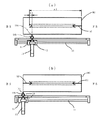
上記した各装置においては、図12に示すように、玉布切断機構が玉布M2が載置される玉布台2Pに設けられている。そして、玉布台2P上で両端切断部位を切断された玉布M2は、玉布供給機構の保持体1Pによって身生地M1上へと移動される。その後、縫製スタートスイッチが押されると、上記のような玉縁縫いが行われる。
【0011】
【発明が解決しようとする課題】
しかしながら、従来の技術には以下のような問題があった。
【0012】
特願平11−34684号の切断機構は、切断部位h2を形成するために一方のメスが常に長い距離L2だけ玉布を切断するので、例えば、図11に示した長尺の玉布M2Bを使用した場合、切り込まれた部分の長さが長くなるため、切断部位の先端部が左右に動き易くなる。
【0013】
そして、前記玉布供給機構は、一般的には図14(a),(b)に示すように玉布M2Bを保持体1Pの左右の針11Pによって保持する構造となっている。短尺の玉布M2Aを保持する場合は図14(a)のように長手方向両端は生地自体の剛性が維持されて垂れ下がることがないが、長尺の玉布M2Bを保持する場合は、切り込み部分M2b,M2bが長いので、切り込まれた部分が細長くなるため剛性が小さくなって図14(b)に示すように大きく垂れ下がってしまう。
【0014】
従って、玉布を身生地上へと載置するべく、図14(b)のまま、玉布供給装置の保持体10Pを下降してしまうと、玉布M2Bは身生地上へと正しく載置されないという問題が生じた。即ち、玉布を身生地上へと移動した際に、玉布M2Bの切り込み後の部分M2b,M2bが、図13(a)に示すように一部重なってしまったり、あるいは13(b)に示すように開いてしまい、玉布が正常に身生地上にセットされず、奇麗な玉縁を形成することができないといった問題が生じた。
【0015】
さらに、特公平2−59760号公報に記載の装置においても、切断長さを設定することができないので、上記の装置と同様に長尺の玉布の場合には、上記と同様の問題を生じることになる。
【0016】
また、上記した各装置は、両端切断部を形成するために2つのメスを必要とする構成であったので、メスの最接近距離というのは物理的に決定されてしまうから、極めて短い玉布には適用することができないという問題を生じていた。
【0017】
そこで、本発明は、玉布を身生地上へと正しく載置することによって、奇麗な玉縁を形成することを目的としている。
【0018】
そこで、本発明の他の目的は、短い玉布の両端切断部位を切断することにある。
【0019】
【課題を解決するための手段】
本発明は、上記問題に鑑みてなされたもので、請求項1に記載の発明は、玉布を身生地上へと重ね合わせた状態で縫い針手前の縫製準備位置から縫い針後方の縫製終了位置へと搬送する布搬送機構と、前記縫製準備位置側方に配置され玉布が載置されると共に、玉布の長手方向位置を決めるための基準線が上面に記された玉布台と、前記玉布台上に載置される玉布を縫製準備位置にある身生地上へと供給する玉布供給機構と、玉布の供給に先立って玉布台上に載置される玉布の長手方向両端切断部位に切り込みを形成する玉布切断機構をして、玉布切断機構により両端切断部位を切断された玉布を、玉布供給機構により縫製準備位置にある身生地上へと供給して重ね合わせた状態で布搬送機構を駆動し、縫製準備位置から縫製終了位置へと移動する間に、布搬送方向に沿って2本の平行な縫い目を形成し、該縫い目間を切断して縫い目よりも若干短いポケット孔を形成し、それぞれのポケット孔の端部にV字状のコーナーカット部を形成する玉縁縫い装置において、前記玉布切断機構を制御する制御部を備え、前記玉布切断機構は、1つのメスと、前記1つのメスを前記玉布台から出没させるエアシリンダと、前記1つのメスを支持すると共に玉布の長手方向に沿って移動可能であり、且つ前記1つのメスよりも玉布の長手方向への長さが長いメス移動台と、前記メス移動台を玉布の長手方向に沿って移動させる駆動モータとを有し、前記制御部は、前記基準線に長手方向の一端を合わせて玉布が前記玉布台に載置された状態で、前記1つのメスの先端部が前記基準線上に位置する原点位置から玉布の一端側の切断部位の切断開始位置まで前記メス移動台を移動させた後、前記1つのメスを前記玉布台上へ突出させてから、前記メス移動台を前記原点位置まで移動させることにより、前記一端側の切断部位を切断すると共に、前記1つのメスを前記玉布台内に埋没させてから、前記メス移動台を前記原点位置から玉布の他端側の切断部位の切断開始位置まで移動させた後、前記1つのメスを前記玉布台上へ突出させてから、前記メス移動台を玉布の長手方向の他端まで移動させることにより、前記他端側の切断部位を切断することを特徴としている。
【0020】
これにより、制御部が玉布切断機構を制御して、両端切断部位は、それぞれ玉布端部からポケット孔の端部と略一致する位置まで切断されるので、両端切断部位を余分に切りすぎてしまうことがなく、玉布を身生地へと正しく載置することができる。
また、玉布切断機構が、1つのメスによって両端切断部位を切断するので、短い玉布の両端切断部位を切断することができるから、装置を短い玉布にも適用範囲を広げることができる。
【0022】
請求項2に記載の発明は、請求項1に記載の玉縁縫い装置において、前記玉布切断機構は、前記メス移動台を玉布の長手方向に沿って移動可能に支持するガイドシャフトと、玉布の長手方向に延在するよう配設され前記駆動モータの駆動軸に張架されると共に、前記メス移動台が固定されたタイミングベルトと、前記メス移動台の原点位置を検出する原点センサと、を備えることを特徴としている。
【0023】
請求項3に記載の発明は、請求項1又は2に記載の玉縁縫い装置において、前記玉布台には、載置される玉布の長手方向に沿って開口溝が形成されていることを特徴としている。
【0024】
【発明の実施の形態】
<全体構成>
玉縁縫い装置の全体構成につき、図1及び図2により説明する。
【0025】
この玉縁縫い装置は、2本の縫い針Nを有する本縫いミシンAと、その手前(図1中右のFS側)のテーブルT上の縫製準備位置P1に上下動可能に配設された逆T字状の保持体Bと、縫製準備位置P1から縫製位置P2、本縫いミシンAの後方(図1中左のBS側)のテーブルT上の縫製終了位置P3へと移動及び逆戻り可能、且つ上下動可能に配設された、折り込み板2付きの大押え1,1を有する布搬送機構Dと、縫製位置P2上に上下動可能に設けられたセンターメス3と、縫製終了位置P3に送り方向に間隔をあけ且つテーブルT上面に対して出没可能に設けられた2つのコーナーメス4とを備えている。
【0026】
また、図1におけるFS側から見た図2に示すように、保持体Bの右側には玉布M2を載置するための玉布台5が配置され、玉布台5の長手方向に沿って開口溝5aが形成されている。
【0027】
そして、テーブルT上に身生地M1をセットした後に、縫製準備位置P1で待機している大押え1、1を下降させて押え、さらに図2(a)に示されるように保持体Bを玉布台5上方へと移動して二点鎖線で示す位置まで下降して玉布M2を保持して上昇し、図2(b)に示されるように保持体Bを身生地M1上へと移動して二点鎖線で示す位置に下降し、図2(c)に示されるように折り込み板2、2を保持体B側に突出させ、逆T字状の保持体Bに沿わせて玉布M2を逆T字形に折り込む。そして、布搬送機構Dを駆動して保持体Bを残したまま大押え1、1と共に身生地M1及び玉布M2が本縫いミシンAの針N下方の縫製位置P2へと移動し、縫い目が形成されると共にセンターメス3によって縫い目間にポケット孔が形成され、縫製終了位置P3でコーナーメス4によってポケット孔の両端にV字形のコーナーカット部(><)が形成されて玉縁縫いが終了する。
<玉布切断機構>
玉布台5には玉布の身生地上への供給に先立って玉布の両端を切断する玉布切断機構が設けられている。玉布切断機構について図3に基づいて説明する。
【0028】
シャフト支持台10は、図3中で斜線で示す位置、すなわち玉布台5の長手方向両端における下端面に固定される。互いに並列し且つ玉布台5の長手方向に沿うように配置された2本のガイドシャフト11、11の両端がシャフト支持台10に固定されている。
【0029】
ガイドシャフト11、11に摺動可能に支持されたメス移動台12は、玉布台5の長手方向に沿ってガイドシャフト11、11上を移動する。メス移動台12には、エアシリンダ13が鉛直方向に動作するように固定され、該エアシリンダ13のシリンダロッド13aには玉布台5の長手方向に設けられる開口溝5aより上面へと出没可能なメス14を設けている。このメス14は、開口溝5aの方向に沿ってFS及びBS側両方に切断刃14a、14bが設けられ、両刃14a,14bの中間に位置する先端部14cが尖った略逆V字状をしている。
【0030】
前記ガイドシャフト11,11の側方には、ガイドシャフト11,11に沿ってタイミングベルト15が配置され、このタイミングベルト15にメス移動台12が固定されている。駆動モータ16が前記BS(図3)側のシャフト支持台10に固定されており、前記タイミングベルト15は、駆動モータ16の駆動軸に固定された回転プーリ16aとFS(図3)側のシャフト支持台10近傍で玉布台5下面に回転可能に設けられた従動プーリ17との間に架け渡されている。駆動モータ16の駆動によって、タイミングベルト15が移動されることにより、メス移動台12を介してメス14が開口溝5aに沿って移動される。
【0031】
原点センサ18は、メス14が開口溝5aのFS側端付近にあるとき、メス移動台12に固定される検出子18aを検出する。
【0032】
また、玉布台5上には基準線5bが記されており、玉布M2を玉布台5上へと載置する時、玉布M2の長手方向における一端を基準線5bに合わせるようにする。
<制御構成>
以上のような玉縁縫い装置の駆動を制御する制御構成について図4に基づいて説明する。
【0033】
制御部20は、CPU(Central Processing Unit)20aと、メモリ20bとを備える。メモリ20bは、縫い始め位置や縫い終わり位置や縫製速度等の縫製データが記憶された縫製データ記憶部20b1と玉縁縫い装置を駆動するためのプログラムが記憶されたプログラム記憶部20b2とを有する。
【0034】
制御部20には、原点センサ18からの検出信号及び操作パネル21の操作による信号が入力されている。制御部20において、原点センサ18の検出信号はメス14の原点位置信号として判断される。操作パネル21からの信号は、縫製データ記憶部20b1への新たな縫製データ、あるいは既に格納されている縫製データの設定変更データ、あるいは玉布切断機構等の駆動の有無を選択する選択信号等として制御部20に判断される。
【0035】
さらに、制御部20にはスタートスイッチ22が接続され、該スイッチ22の操作によって玉縁縫い装置が起動される。
【0036】
次に、制御部20の出力側には、制御部20からの出力信号に応じて回転を制御される駆動モータとしてのステッピングモータ16が接続され、メス14が玉布台5の開口溝5aに沿って所定速度で移動される。
【0037】
布搬送機構Dの駆動手段23は、大押え1を布搬送方向(BS−FS方向)に移動するサーボモータ、大押え1を上下動するエアシリンダ、折り込み板2を出没させるエアシリンダ等を含む。
【0038】
玉布供給機構の駆動手段24は、保持体Bを上下動するエアシリンダ、保持体Bを玉布台5とテーブルTとの間に移動するエアシリンダ等を含む。
【0039】
ミシン駆動手段25は、ミシンモータ等のミシン本体A内に配置された駆動源を含む。
【0040】
さらに制御部20には、センターメス3を上下動するためのエアシリンダやコーナーメス4を上下動するためのエアシリンダ等の各種アクチュエータや各種センサが接続されている。
<玉布切断動作>
玉布切断動作について、図5の動作フローを中心に説明する。
【0041】
CPU20aによって玉布切断機構のメス移動台12の移動量を演算する(ステップ1)。スタートスイッチ22のONを待ち(ステップ2)、スタートスイッチ22がONされると、検出子18aが原点センサ18に検出されるようにメス移動台12を移動する原点検索処理を行う(ステップ3)。具体的には、図6に示すように、ステップ4において原点センサ18が検出子18aを検知しているかどうかを判断し、検知している場合、ステップ5でメス移動台12をBS方向へと移動し、ステップ4、ステップ5を原点センサ18が検出子18aを検知しなくなるまで繰り返し、原点センサ18が検出子18aを検知しなくなった場合、ステップ6でメス移動台12をFS方向へと移動する。ステップ7では再び原点センサ18が検出子18aを検知しているかどうかを判断し、検知されない場合、ステップ6へと戻り、すなわち検知するまでメス移動台12をFS方向へと移動し続ける。原点センサ18が検出子18aを検知すると、ステップ8へと進みメス移動台12の移動を停止して原点検索処理を終了する。
【0042】
原点検索処理後のメス移動台12は図7(a)に示す原点位置へと移動している。この時、メス14の先端部14cが玉布M2のFS側端と一致している。なお、メス14と玉布M2との長手方向における位置関係がわかるように図7、図8においてはそれぞれ縫い目S、ポケット孔H、コーナーカット部Cが形成された状態の玉布M2を上方に並べて示している。
【0043】
図5に戻り、ステップ9において、ステップ3の演算結果に基づいてメス移動台12が図7(b)に示す玉布カット位置へと移動する。メス移動台12の原点位置からカット位置への移動量は以下の要領で算出される。
【0044】
縫製データ記憶部20b1(図3)には、予め縫製に必要なデータとして、操作パネル21により設定された玉布M2の一端から縫製終了位置までの距離x1が記憶されており、玉布M2の一端と原点位置とが一致していることから原点位置から縫製終了位置までの距離もx1となり、これに所定量としてd1を加えることにより、移動量X1を得ることができる。すなわち、移動量X1は、
X1=x1+d1
によって算出される。ここで、所定量をd1としているが、これは、ポケット孔Hの形成が終了する位置が、縫製終了位置からおよそd1だけBS側へと入り込んだ位置となるからであり、本実施の形態では、10mmに設定されている。なお、メス土台12の移動量は、切断動作の迅速化という観点からすると、本実施の形態のようにステップ1のような玉布切断動作前に算出しておくことが望ましいが、本発明を実現することだけを考えれば、メス移動台12を移動するステップ9直前に算出しても差し支えない。
【0045】
これによって、メス移動台12はメス14の先端部14cとポケット孔Hの形成が終了する位置とが略一致するところまで移動されるので、図7(b)の実線で示すように切断開始位置(切断端)がポケット孔の端部と略一致する。
【0046】
次いで、ステップ10において、エアシリンダ13の駆動によりメス14を玉布台5上へと突出させ、図7(b)に二点鎖線で示すように玉布M2を貫通する。ステップ11において、メス移動台12を原点位置まで移動してFS側の切断刃14aにより玉布M2のFS側の両端切断部位h1を切断し、ステップ12にてエアシリンダ13を駆動して図7(c)に示すようにメス14を下降する。
【0047】
続いて、ステップ13において、BS側の切断部位h2をカットするべく、メス移動台12を図8(a)に示す玉布カット位置へと移動する。メス移動台12の原点位置からカット位置への移動量は以下の要領で算出される。
【0048】
縫製データ記憶部20b1(図3)には、予め縫製に必要なデータとして、操作パネル21により設定された玉布M2の一端から縫製開始位置までの距離x2が記憶されており、玉布M2の一端と原点位置とが一致していることから原点位置から縫製開始位置までの距離もx2となり、これに所定量としてd2を減じることにより、移動量X2を得ることができる。すなわち、移動量X2は、
X2=x2−d2
によって算出される。ここで、所定量をd2としているが、これは、ポケット孔Hの形成を開始する位置が、縫製開始位置からおよそd2だけFS側へと入り込んだ位置となるからであり、本実施の形態では、10mmに設定されている。なお、メス土台12の移動量は、切断動作の迅速化という観点からすると、本実施の形態のようにステップ1のような玉布切断動作前に算出しておくことが望ましいが、本発明を実現することだけを考えれば、メス移動台12を移動するステップ13直前に算出しても差し支えない。
【0049】
これによって、メス移動台12はメス14の先端部14cとポケット孔Hの形成を開始する位置とが略一致するところまで移動されるので、切断開始位置(切断端)がポケット孔の端部と略一致する。
【0050】
次いで、ステップ14において、エアシリンダ13を駆動し、図8(a)に二点鎖線で示すようにメス14を玉布台5上へと突出させ玉布M2を貫通する。ステップ15において、図8(b)に実線で示すようにメス14の先端部14cが玉布M2のBS側端と一致するまでメス移動台12を移動することにより、BS側の切断刃14bによって玉布M2のBS側の切断部位h2を切断し、ステップ16において、エアシリンダ13を駆動して図8(b)に二点鎖線で示すようにメス14を下降する。そして、ステップ17にてメス移動台12を原点位置へと移動して(図7(a))玉布切断動作を終了する。
【0051】
これにより、メス14は両端切断部位h1,h2をポケット孔の両端部と略一致するところまで切断して形成するので、保持体Bにより玉布M2を身生地上へと供給する際に玉布M2が変形して載置されてしまうということがなく、玉布を身生地へと正しく載置することができる。
【0052】
また、1つのメスによって両端切断部位を切断するので、短い玉布の両端切断部位を切断することができるから、装置を短い玉布にも適用範囲を広げることができる。
【0053】
なお、本発明の主旨を逸脱しない範囲において、種々の変更が可能であることは言うまでもない。
【0054】
【発明の効果】
本発明によれば、制御部が玉布切断機構を制御して、両端切断部位は、それぞれ玉布端部からポケット孔の端部と略一致する位置まで切断されるので、両端切断部位を余分に切りすぎてしまうことがなく、玉布を身生地へと正しく載置することができる。
【0055】
また、玉布切断機構が、1つのメスによって両端切断部位を切断するので、短い玉布の両端切断部位を切断することができるから、装置を短い玉布にも適用範囲を広げることができる。
【図面の簡単な説明】
【図1】玉縁縫い装置の概略斜視図。
【図2】玉布を身生地上へと供給する動作を説明する説明図。
【図3】本発明の玉布切断機構の概略斜視図。
【図4】本発明の制御構成を示すブロック図。
【図5】本発明の玉布切断機構の動作フロー。
【図6】本発明の玉布切断機構の原点検索処理フロー。
【図7】本発明の玉布切断機構がFS側の切断部位の切断動作を説明する説明図。
【図8】本発明の玉布切断機構がBS側の切断部位の切断動作を説明する説明図。
【図9】玉縁縫い装置によって縫製された玉縁。
【図10】(a)完成した玉縁を裏側から見た図。(b)両端切断部位を切断していないときのA−A断面図。(c)両端切断部位を切断したときのA−A断面図。
【図11】従来の玉布切断機構における切断領域を説明した説明図。
【図12】玉布を身生地上へと供給する動作を説明する説明図。
【図13】玉布を身生地上へと供給する際に玉布が変形してしまった例を示す図。
【図14】玉布切断機構が切断部位を余分に切断した玉布を保持体が保持した時の不具合を説明する説明図。
【符号の説明】
A ・・・・・ ミシン本体
B ・・・・・ 玉布供給機構の保持体
D ・・・・・ 布搬送機構
5 ・・・・・ 玉布台
12 ・・・・・ メス支持台
13 ・・・・・ エアシリンダ
14 ・・・・・ メス
14a ・・・・・ FS側切断刃
14b ・・・・・ BS側切断刃
14c ・・・・・ 先端部
16 ・・・・・ ステッピングモータ
18 ・・・・・ 原点センサ
20 ・・・・・ 制御部
20a ・・・・・ CPU
20b ・・・・・ メモリ
20b1 ・・・・・ 縫製データ記憶部
20b2 ・・・・・ プログラム記憶部[0001]
BACKGROUND OF THE INVENTION
The present invention relates to a bead stitching device for performing bead stitching on a bead cloth constituted by a body cloth and a bead supplied on the cloth through a desired sewing process.
[0002]
[Prior art]
Sewing called edge stitch sewing as shown in FIG. 9A is performed on the opening of the pocket.
[0003]
The formation of the ball edge stitches is performed by sewing two parallel seams S and S on the body fabric M1 on the cloth M2 with both side edges folded upward (inverted T-shape) and at the same time with the center knife. A pocket hole H is formed in the middle of the seams S, S along the seam line and shorter than the seams S, S, and thereafter, from the both ends of the pocket hole H to the seams S, S ends by the V-shaped corner knife, respectively. The corner cut portions C and C are opened so as to extend.
[0004]
When the ball cloth M2 is returned once through the pocket hole H after the end of sewing, the state shown in FIG.
[0005]
Usually, after sewing the ball edge, an iron is applied from the back side of the body cloth M1 in order to adjust the crease of the
[0006]
In order to avoid such problems, a method is known in which both ends of the pocket hole H are cut from both ends of the pocket hole H to both ends of the ball cloth M2 on the extended line of the pocket hole H before the edge stitching is performed. It has been. Thus, if both ends cutting part h and h are formed, both ends of the overlapped ball cloth M2 can be opened outside as shown in Drawing 10 (C), and both ends of ball cloth M2 do not become thick. Therefore, the above problem can be solved.
[0007]
The present applicant has filed Japanese Patent Application No. 11-34684 as a device for cutting the both ends cutting portion of the ball cloth M2. This apparatus cuts the both ends cutting part of the ball cloth by moving two scalpels arranged on a straight line from the inner side to the outer side with respect to the ball cloth placed with one end as a reference. .
[0008]
In the invention of the application, since the knife is moved by the air cylinder, for example, as shown in FIG. 11, the knife always operates to cut a predetermined cutting region. In FIG. 11, M2A is the shortest ball cloth used when the pocket hole H has the minimum length, and M2B is the longest ball cloth used when the pocket hole H has the maximum length. Then, when both are placed on the bedcloth stand, they are placed with their left ends (FIG. 11) aligned. Accordingly, the left cut portion h1 that is aligned is set at the same position in the shortest ball M2A and the longest ball cloth M2B and the length of the cut region is L1, but one right cut portion h2 is the shortest ball h2 The positions of the cloth M2A and the longest ball cloth M2B are significantly different from each other. In order to enable the cutting of both, the length of the right cutting area is set to the length L2 including both. That is, by changing the cutting area on the right side, it corresponds to the change in the length of the used cloth.
[0009]
Another cutting mechanism is disclosed in Japanese Patent Publication No. 2-59760. The cutting mechanism disclosed in Japanese Examined Patent Publication No. 2-59760 drives two rotary cutters arranged on the same straight line corresponding to each of both end cutting portions by a motor.
[0010]
In each device described above, as shown in FIG. 12, a ball cutting mechanism is provided on a ball base 2P on which the
[0011]
[Problems to be solved by the invention]
However, the conventional techniques have the following problems.
[0012]
In the cutting mechanism of Japanese Patent Application No. 11-34684, one knife always cuts the ball cloth by a long distance L2 in order to form the cutting part h2, so for example, the long cotton cloth M2B shown in FIG. When used, the length of the cut portion becomes longer, so that the distal end portion of the cut portion can easily move left and right.
[0013]
And as shown in FIGS. 14 (a) and 14 (b), the ball supply mechanism is generally configured to hold the ball M2B by the left and right needles 11P of the holding body 1P. When holding the short length of M2A, as shown in FIG. 14 (a), both ends in the longitudinal direction maintain the rigidity of the fabric itself and do not hang down. Since M2b and M2b are long, the cut portion is elongated and the rigidity is reduced, and droops greatly as shown in FIG.
[0014]
Therefore, if the holder 10P of the drape supply device is lowered as shown in FIG. 14B in order to place the drape on the cloth, the drape M2B is correctly placed on the cloth. The problem that was not done. That is, when the ball cloth is moved onto the cloth, the portions M2b and M2b after the cut of the ball cloth M2B are partially overlapped as shown in FIG. As shown in the figure, it opened, and the drapery was not properly set on the cloth, resulting in a problem that a beautiful bead could not be formed.
[0015]
Furthermore, even in the apparatus described in Japanese Patent Publication No. 2-59760, the cutting length cannot be set, so that the same problem as described above occurs in the case of a long glove similar to the above apparatus. It will be.
[0016]
In addition, since each of the above-described devices has a configuration that requires two scalpels in order to form both-end cut portions, the closest approach distance of the scalpel is physically determined, so an extremely short tapping Had a problem that could not be applied.
[0017]
Therefore, the present invention has an object to form a beautiful bead by correctly placing a drape onto a body cloth.
[0018]
Then, the other objective of this invention is to cut | disconnect the both-ends cutting site | part of a short ball cloth.
[0019]
[Means for Solving the Problems]
The present invention has been made in view of the above problems, and the invention according to
[0020]
As a result, the control unit controls the ball cutting mechanism, and the both end cutting parts are cut from the end of the ball cloth to the position substantially coincident with the end of the pocket hole. It is possible to place the drapes correctly on the body cloth.
In addition, since the end cutting part is cut by the single knife with the knife cutting mechanism, the both end cutting part of the short ball can be cut, so that the range of application of the apparatus can be extended to a short head.
[0022]
The invention according to
[0023]
According to a third aspect of the present invention, in the bead stitching device according to the first or second aspect , an opening groove is formed in the ball bed base along the longitudinal direction of the placed ball. It is characterized by.
[0024]
DETAILED DESCRIPTION OF THE INVENTION
<Overall configuration>
The overall configuration of the edge stitch device will be described with reference to FIGS. 1 and 2.
[0025]
This bead stitching device is disposed so as to be movable up and down at a sewing preparation position P1 on a table T in front of (a FS side on the right side in FIG. 1) a main sewing machine A having two sewing needles N. Reverse T-shaped holding body B, and can be moved and returned from the sewing preparation position P1 to the sewing position P2, and to the sewing end position P3 on the table T behind the main sewing machine A (the BS side on the left in FIG. 1). In addition, the cloth conveying mechanism D having the
[0026]
Further, as shown in FIG. 2 as viewed from the FS side in FIG. 1, a ball cloth table 5 for placing the ball cloth M <b> 2 is disposed on the right side of the holding body B, and along the longitudinal direction of the ball cloth table 5. Thus, an opening groove 5a is formed.
[0027]
Then, after setting the fabric M1 on the table T, the
<Dabing mechanism>
The ball cloth table 5 is provided with a ball cutting mechanism for cutting both ends of the ball cloth prior to the supply of the ball cloth onto the body cloth. The ball cloth cutting mechanism will be described with reference to FIG.
[0028]
The
[0029]
The knife moving table 12 slidably supported on the
[0030]
A timing belt 15 is disposed on the side of the
[0031]
The
[0032]
Further, a reference line 5b is written on the ball cloth table 5, and when the ball cloth M2 is placed on the ball cloth table 5, one end in the longitudinal direction of the ball cloth M2 is aligned with the reference line 5b. To do.
<Control configuration>
A control configuration for controlling the driving of the above-described edge stitch device will be described with reference to FIG.
[0033]
The
[0034]
A detection signal from the
[0035]
Further, a start switch 22 is connected to the
[0036]
Next, a stepping
[0037]
The driving means 23 of the cloth conveying mechanism D includes a servo motor that moves the
[0038]
The driving means 24 of the ball cloth supply mechanism includes an air cylinder that moves the holding body B up and down, an air cylinder that moves the holding body B between the ball cloth table 5 and the table T, and the like.
[0039]
The sewing machine driving means 25 includes a driving source arranged in the sewing machine main body A such as a sewing machine motor.
[0040]
Furthermore, various actuators and various sensors such as an air cylinder for moving the
<Dabing cutting operation>
The ball cloth cutting operation will be described focusing on the operation flow of FIG.
[0041]
The CPU 20a calculates the amount of movement of the knife moving table 12 of the ball cutting mechanism (step 1). Waiting for the start switch 22 to turn on (step 2), when the start switch 22 is turned on, an origin search process is performed to move the knife moving table 12 so that the detector 18a is detected by the origin sensor 18 (step 3). . Specifically, as shown in FIG. 6, it is determined whether or not the
[0042]
The knife moving table 12 after the origin search process has moved to the origin position shown in FIG. At this time, the
[0043]
Returning to FIG. 5, in step 9, the scalpel moving table 12 moves to the drape cutting position shown in FIG. 7B based on the calculation result of
[0044]
The sewing data storage unit 20b1 (FIG. 3) stores a distance x1 from one end of the ball cloth M2 set by the operation panel 21 to the sewing end position as data necessary for sewing in advance. Since the one end coincides with the origin position, the distance from the origin position to the sewing end position is also x1, and by adding d1 as a predetermined amount to this, the movement amount X1 can be obtained. That is, the movement amount X1 is
X1 = x1 + d1
Is calculated by Here, the predetermined amount is d1, which is because the position where the formation of the pocket hole H is finished is a position that enters the BS side by about d1 from the sewing end position. 10 mm is set. In addition, from the viewpoint of speeding up the cutting operation, it is desirable that the amount of movement of the
[0045]
As a result, the knife moving table 12 is moved to a position where the
[0046]
Next, in
[0047]
Subsequently, in
[0048]
The sewing data storage unit 20b1 (FIG. 3) stores a distance x2 from one end of the ball cloth M2 set by the operation panel 21 to the sewing start position as data necessary for sewing in advance. Since the one end and the origin position coincide with each other, the distance from the origin position to the sewing start position is also x2, and the movement amount X2 can be obtained by subtracting d2 as a predetermined amount. That is, the movement amount X2 is
X2 = x2-d2
Is calculated by Here, the predetermined amount is d2, which is because the position at which the formation of the pocket hole H is started is a position that enters the FS side by approximately d2 from the sewing start position. 10 mm is set. In addition, from the viewpoint of speeding up the cutting operation, it is desirable that the amount of movement of the
[0049]
As a result, the knife moving table 12 is moved to a position where the
[0050]
Next, in
[0051]
As a result, the
[0052]
Moreover, since the both ends cutting site | part is cut | disconnected by one scalpel, since the both ends cutting site | part of a short bead can be cut | disconnected, an application range can be extended also to a short bead.
[0053]
In addition, it cannot be overemphasized that a various change is possible in the range which does not deviate from the main point of this invention.
[0054]
【The invention's effect】
According to the present invention , the control unit controls the ball cutting mechanism, and the both end cutting parts are cut from the end of the ball cloth to the position substantially coinciding with the end of the pocket hole. Therefore, it is possible to place the drapes correctly on the cloth.
[0055]
In addition , since the end cutting part is cut by the single knife with the knife cutting mechanism, the both end cutting part of the short ball can be cut, so that the range of application of the apparatus can be extended to a short head.
[Brief description of the drawings]
FIG. 1 is a schematic perspective view of a bead stitching device.
FIG. 2 is an explanatory diagram for explaining an operation for supplying a drape onto a body cloth.
FIG. 3 is a schematic perspective view of a ball cutting mechanism according to the present invention.
FIG. 4 is a block diagram showing a control configuration of the present invention.
FIG. 5 is an operation flow of the ball cutting mechanism according to the present invention.
FIG. 6 is an origin search process flow of the tart cutting mechanism according to the present invention.
FIG. 7 is an explanatory view for explaining the cutting operation of the cutting part on the FS side by the ball cutting mechanism of the present invention.
FIG. 8 is an explanatory diagram for explaining the cutting operation of the cutting site on the BS side by the ball-cloth cutting mechanism of the present invention.
FIG. 9 shows a bead sewn by a bead stitching device.
FIG. 10A is a view of a completed ball edge viewed from the back side. (B) AA sectional drawing when the both-end cutting site is not cut. (C) AA sectional drawing when cut | disconnecting a both-ends cutting site | part.
FIG. 11 is an explanatory diagram for explaining a cutting area in a conventional ball cutting mechanism.
FIG. 12 is an explanatory diagram for explaining an operation for supplying a drape onto a body cloth.
FIG. 13 is a view showing an example in which the ball cloth is deformed when the ball cloth is supplied onto the body cloth.
FIG. 14 is an explanatory view for explaining a problem when a holding body holds a tamago whose cutting part has been cut off excessively by a garment cutting mechanism.
[Explanation of symbols]
A ...... Sewing machine body B ...... Holding body D of the cloth supply mechanism ......
20b ... Memory 20b1 ... Sewing data storage 20b2 ... Program storage
Claims (3)
前記玉布切断機構を制御する制御部を備え、
前記玉布切断機構は、1つのメスと、前記1つのメスを前記玉布台から出没させるエアシリンダと、前記1つのメスを支持すると共に玉布の長手方向に沿って移動可能であり、且つ前記1つのメスよりも玉布の長手方向への長さが長いメス移動台と、前記メス移動台を玉布の長手方向に沿って移動させる駆動モータとを有し、
前記制御部は、
前記基準線に長手方向の一端を合わせて玉布が前記玉布台に載置された状態で、前記1つのメスの先端部が前記基準線上に位置する原点位置から玉布の一端側の切断部位の切断開始位置まで前記メス移動台を移動させた後、前記1つのメスを前記玉布台上へ突出させてから、前記メス移動台を前記原点位置まで移動させることにより、前記一端側の切断部位を切断すると共に、
前記1つのメスを前記玉布台内に埋没させてから、前記メス移動台を前記原点位置から玉布の他端側の切断部位の切断開始位置まで移動させた後、前記1つのメスを前記玉布台上へ突出させてから、前記メス移動台を玉布の長手方向の他端まで移動させることにより、前記他端側の切断部位を切断することを特徴とする玉縁縫い装置。A cloth transport mechanism that transports the cloth from the sewing preparation position in front of the sewing needle to the sewing end position behind the sewing needle in a state where the ball cloth is superimposed on the body cloth, and the cloth arranged on the side of the sewing preparation position. And the base material on which the reference line for determining the longitudinal position of the ball cloth is marked on the upper surface and the ball cloth placed on the ball cloth table onto the body cloth at the sewing preparation position A supply mechanism for supplying the yarn, and a cutting mechanism for forming a cut at both ends in the longitudinal direction of the ball placed on the bed before the supply of the yarn. The fabric feed mechanism is driven from the sewing preparation position to the sewing end position by supplying the overlapped fabric from the both ends cutting portion onto the body cloth at the sewing preparation position and superimposing it. And forming two parallel seams along the cloth conveying direction, In the cutting to form a slightly shorter pockets pores than the seam, welting apparatus for forming a corner cut portion of the V-shape ends of the respective pocket holes,
A control unit for controlling the ball-cloth cutting mechanism;
The ball cutting mechanism is capable of moving along the longitudinal direction of the ball while supporting the one knife, an air cylinder that causes the one knife to protrude from the table, and supporting the one knife. A knife moving table having a longer length in the longitudinal direction of the ball than the one knife, and a drive motor for moving the knife moving table along the longitudinal direction of the ball,
The controller is
Cutting one end side of the ball from the origin position where the tip of the one knife is located on the reference line in a state where the end of the longitudinal direction is aligned with the reference line and the ball is placed on the table. After moving the knife moving table to the cutting start position of the part, the one knife is projected onto the ball cloth table, and then the knife moving table is moved to the origin position, thereby Cutting the cleavage site,
After the one knife is buried in the bedcloth table, the knife moving table is moved from the origin position to the cutting start position of the cutting site on the other end side of the ballcloth, and then the one knife is moved to the An edge stitching device characterized by cutting the cut portion on the other end side by causing the knife moving table to move to the other end in the longitudinal direction of the ball cloth after protruding onto the ball cloth table .
前記メス移動台を玉布の長手方向に沿って移動可能に支持するガイドシャフトと、
玉布の長手方向に延在するよう配設され前記駆動モータの駆動軸に張架されると共に、前記メス移動台が固定されたタイミングベルトと、
前記メス移動台の原点位置を検出する原点センサと、
を備えることを特徴とする請求項1に記載の玉縁縫い装置。The above-mentioned ball cloth cutting mechanism is
A guide shaft that supports the knife moving table so as to be movable along the longitudinal direction of the ball cloth;
A timing belt which is disposed so as to extend in the longitudinal direction of the ball cloth and is stretched around the drive shaft of the drive motor, and to which the knife moving table is fixed;
An origin sensor for detecting the origin position of the knife moving table;
The bead stitching device according to claim 1 , comprising:
Priority Applications (4)
| Application Number | Priority Date | Filing Date | Title |
|---|---|---|---|
| JP2001006169A JP4489979B2 (en) | 2000-01-14 | 2001-01-15 | Ball stitching device |
| DE2001102406 DE10102406B4 (en) | 2000-01-14 | 2001-01-15 | Device for cutting a piping strip and transferring the piping strip to a main sewing material |
| DE10164827A DE10164827B4 (en) | 2000-01-14 | 2001-01-15 | Clamp fitting to hold a pane of glass has a cone nut within a drilling through the pane with a shrouding cover in a release mounting through a clip closure |
| CNB011004711A CN1322190C (en) | 2000-01-14 | 2001-01-15 | Device for sewing panel |
Applications Claiming Priority (5)
| Application Number | Priority Date | Filing Date | Title |
|---|---|---|---|
| JP2000005489 | 2000-01-14 | ||
| JP2000-5489 | 2000-12-18 | ||
| JP2000383543 | 2000-12-18 | ||
| JP2000-383543 | 2000-12-18 | ||
| JP2001006169A JP4489979B2 (en) | 2000-01-14 | 2001-01-15 | Ball stitching device |
Publications (3)
| Publication Number | Publication Date |
|---|---|
| JP2002248282A JP2002248282A (en) | 2002-09-03 |
| JP2002248282A5 JP2002248282A5 (en) | 2008-02-21 |
| JP4489979B2 true JP4489979B2 (en) | 2010-06-23 |
Family
ID=27342036
Family Applications (1)
| Application Number | Title | Priority Date | Filing Date |
|---|---|---|---|
| JP2001006169A Expired - Fee Related JP4489979B2 (en) | 2000-01-14 | 2001-01-15 | Ball stitching device |
Country Status (3)
| Country | Link |
|---|---|
| JP (1) | JP4489979B2 (en) |
| CN (1) | CN1322190C (en) |
| DE (1) | DE10102406B4 (en) |
Families Citing this family (12)
| Publication number | Priority date | Publication date | Assignee | Title |
|---|---|---|---|---|
| JP4236454B2 (en) | 2002-12-05 | 2009-03-11 | Juki株式会社 | Ball sewing machine |
| JP2006263185A (en) * | 2005-03-24 | 2006-10-05 | Juki Corp | Binding sewing machine |
| JP4681967B2 (en) * | 2005-07-26 | 2011-05-11 | Juki株式会社 | Sewing sewing machine |
| JP4769505B2 (en) * | 2005-07-27 | 2011-09-07 | Juki株式会社 | Sewing sewing machine |
| JP4799946B2 (en) * | 2005-07-29 | 2011-10-26 | Juki株式会社 | Sewing sewing machine |
| JP2007089987A (en) * | 2005-09-30 | 2007-04-12 | Juki Corp | Sewing machine for binding |
| JP4769534B2 (en) * | 2005-10-03 | 2011-09-07 | Juki株式会社 | Large presser for sewing machine |
| JP4823643B2 (en) * | 2005-10-24 | 2011-11-24 | Juki株式会社 | Sewing sewing machine |
| JP2008054988A (en) * | 2006-08-31 | 2008-03-13 | Juki Corp | Piping sewing machine |
| JP5468236B2 (en) * | 2007-10-31 | 2014-04-09 | Juki株式会社 | Sewing sewing machine |
| JP5312135B2 (en) * | 2009-03-26 | 2013-10-09 | Juki株式会社 | Sewing machine supply device |
| GB2497308A (en) * | 2011-12-06 | 2013-06-12 | Montfort Services Sdn Bhd | Work positioning sewing machine |
Citations (8)
| Publication number | Priority date | Publication date | Assignee | Title |
|---|---|---|---|---|
| JPS6397197A (en) * | 1986-10-14 | 1988-04-27 | ブラザー工業株式会社 | Automatic cutter of sewing machine |
| JPH02255175A (en) * | 1989-03-09 | 1990-10-15 | Duerkoppwerke Gmbh | Sewing machine with device for moving piping piece having cut at center of both ends |
| JPH0259760B2 (en) * | 1985-09-06 | 1990-12-13 | Beisler Gmbh | |
| JPH05192470A (en) * | 1992-01-23 | 1993-08-03 | Barudan Co Ltd | Towel forming device |
| JPH06246078A (en) * | 1993-02-25 | 1994-09-06 | Juki Corp | Sewing machine |
| JPH07313758A (en) * | 1994-05-26 | 1995-12-05 | Juki Corp | Bead sewing machine |
| JPH0931837A (en) * | 1995-07-21 | 1997-02-04 | Janome Sewing Mach Co Ltd | Cutting plotter |
| JPH10314477A (en) * | 1997-04-29 | 1998-12-02 | Duerkopp Adler Ag | Device for transferring piping stripe from supply station to part of sawed object |
Family Cites Families (7)
| Publication number | Priority date | Publication date | Assignee | Title |
|---|---|---|---|---|
| FR2412635A1 (en) * | 1977-12-21 | 1979-07-20 | Reece Machinery Cy France Sa | IMPROVEMENTS IN MACHINES USED TO MANUFACTURE PIPED OPENINGS IN A PIECE OF FABRIC OR SIMILAR |
| CN85105507A (en) * | 1985-07-18 | 1987-01-21 | 东京重机工业株式会社 | Fringing forms the driving control device of device |
| JPS6426775A (en) * | 1987-07-16 | 1989-01-30 | Takatori Corp | Apparatus for automatically cutting cloth |
| JPH10137464A (en) * | 1996-11-13 | 1998-05-26 | Juki Corp | Binding machine |
| DE19845624C1 (en) * | 1998-10-05 | 2000-05-11 | Duerkopp Adler Ag | Sewing system for producing a piped pocket opening |
| DE19845623C1 (en) * | 1998-10-05 | 2000-02-17 | Duerkopp Adler Ag | Cutters on twin needle sewing machine for making piped pocket openings are mounted in frame that can swing clear of worktable |
| DE19908894C1 (en) * | 1999-03-02 | 2000-08-03 | Beisler Gmbh | Sewing piped openings for pockets involves making corner cuts with angled knives that can be swung about axis running through their point of intersection |
-
2001
- 2001-01-15 CN CNB011004711A patent/CN1322190C/en not_active Expired - Lifetime
- 2001-01-15 JP JP2001006169A patent/JP4489979B2/en not_active Expired - Fee Related
- 2001-01-15 DE DE2001102406 patent/DE10102406B4/en not_active Expired - Fee Related
Patent Citations (8)
| Publication number | Priority date | Publication date | Assignee | Title |
|---|---|---|---|---|
| JPH0259760B2 (en) * | 1985-09-06 | 1990-12-13 | Beisler Gmbh | |
| JPS6397197A (en) * | 1986-10-14 | 1988-04-27 | ブラザー工業株式会社 | Automatic cutter of sewing machine |
| JPH02255175A (en) * | 1989-03-09 | 1990-10-15 | Duerkoppwerke Gmbh | Sewing machine with device for moving piping piece having cut at center of both ends |
| JPH05192470A (en) * | 1992-01-23 | 1993-08-03 | Barudan Co Ltd | Towel forming device |
| JPH06246078A (en) * | 1993-02-25 | 1994-09-06 | Juki Corp | Sewing machine |
| JPH07313758A (en) * | 1994-05-26 | 1995-12-05 | Juki Corp | Bead sewing machine |
| JPH0931837A (en) * | 1995-07-21 | 1997-02-04 | Janome Sewing Mach Co Ltd | Cutting plotter |
| JPH10314477A (en) * | 1997-04-29 | 1998-12-02 | Duerkopp Adler Ag | Device for transferring piping stripe from supply station to part of sawed object |
Also Published As
| Publication number | Publication date |
|---|---|
| DE10102406B4 (en) | 2006-05-24 |
| CN1322190C (en) | 2007-06-20 |
| DE10102406A1 (en) | 2001-11-15 |
| JP2002248282A (en) | 2002-09-03 |
| CN1319694A (en) | 2001-10-31 |
Similar Documents
| Publication | Publication Date | Title |
|---|---|---|
| JP4489979B2 (en) | Ball stitching device | |
| JP4149630B2 (en) | Sewing sewing machine | |
| JP5759158B2 (en) | Belt loop sewing machine and belt loop folding method | |
| US7739972B2 (en) | Method and apparatus for producing a sewn product | |
| JP2008200129A (en) | Welting machine | |
| KR950032802A (en) | Welt Forming Device, Control Method and Fabric Guide | |
| JPH0262273B2 (en) | ||
| JP5160030B2 (en) | Button sewing machine and button attaching method | |
| JP2006263185A (en) | Binding sewing machine | |
| JPH0311797B2 (en) | ||
| EP0491056A1 (en) | Sewing method and device | |
| JP5468222B2 (en) | Sewing sewing machine | |
| JP2513050Y2 (en) | Cloth edge guide device for sewing machine for bi-fold fabric sewing | |
| JP5174423B2 (en) | Sewing sewing machine | |
| JP3990757B2 (en) | Zigzag sewing machine | |
| JPH0319347Y2 (en) | ||
| JP4235304B2 (en) | Tamagawa feeder | |
| JP4522540B2 (en) | Drilling machine control device | |
| JP4739594B2 (en) | Eyelet hole sewing machine and method for forming eyelet stitching | |
| JP3641314B2 (en) | Tamagawa reversing device | |
| JP4681765B2 (en) | Sewing machine cloth guide device and sewing machine | |
| GB2214054A (en) | Method and apparatus for inserting gussets into garments | |
| JPS599189B2 (en) | Sewing machine cloth control device | |
| JPH06319881A (en) | Sewing machine for tatami mat | |
| JP4921654B2 (en) | Work sewing device and sewing method |
Legal Events
| Date | Code | Title | Description |
|---|---|---|---|
| A521 | Written amendment |
Free format text: JAPANESE INTERMEDIATE CODE: A523 Effective date: 20071228 |
|
| A621 | Written request for application examination |
Free format text: JAPANESE INTERMEDIATE CODE: A621 Effective date: 20071228 |
|
| A977 | Report on retrieval |
Free format text: JAPANESE INTERMEDIATE CODE: A971007 Effective date: 20090515 |
|
| A131 | Notification of reasons for refusal |
Free format text: JAPANESE INTERMEDIATE CODE: A131 Effective date: 20090526 |
|
| A521 | Written amendment |
Free format text: JAPANESE INTERMEDIATE CODE: A523 Effective date: 20090727 Free format text: JAPANESE INTERMEDIATE CODE: A821 Effective date: 20090727 |
|
| RD02 | Notification of acceptance of power of attorney |
Free format text: JAPANESE INTERMEDIATE CODE: A7422 Effective date: 20090727 |
|
| A131 | Notification of reasons for refusal |
Free format text: JAPANESE INTERMEDIATE CODE: A131 Effective date: 20091006 |
|
| A521 | Written amendment |
Free format text: JAPANESE INTERMEDIATE CODE: A523 Effective date: 20091202 |
|
| TRDD | Decision of grant or rejection written | ||
| A01 | Written decision to grant a patent or to grant a registration (utility model) |
Free format text: JAPANESE INTERMEDIATE CODE: A01 Effective date: 20100323 |
|
| A01 | Written decision to grant a patent or to grant a registration (utility model) |
Free format text: JAPANESE INTERMEDIATE CODE: A01 |
|
| A61 | First payment of annual fees (during grant procedure) |
Free format text: JAPANESE INTERMEDIATE CODE: A61 Effective date: 20100401 |
|
| FPAY | Renewal fee payment (event date is renewal date of database) |
Free format text: PAYMENT UNTIL: 20130409 Year of fee payment: 3 |
|
| R150 | Certificate of patent or registration of utility model |
Ref document number: 4489979 Country of ref document: JP Free format text: JAPANESE INTERMEDIATE CODE: R150 Free format text: JAPANESE INTERMEDIATE CODE: R150 |
|
| FPAY | Renewal fee payment (event date is renewal date of database) |
Free format text: PAYMENT UNTIL: 20130409 Year of fee payment: 3 |
|
| FPAY | Renewal fee payment (event date is renewal date of database) |
Free format text: PAYMENT UNTIL: 20140409 Year of fee payment: 4 |
|
| LAPS | Cancellation because of no payment of annual fees |