JP4464016B2 - Game machine - Google Patents
Game machine Download PDFInfo
- Publication number
- JP4464016B2 JP4464016B2 JP2001258939A JP2001258939A JP4464016B2 JP 4464016 B2 JP4464016 B2 JP 4464016B2 JP 2001258939 A JP2001258939 A JP 2001258939A JP 2001258939 A JP2001258939 A JP 2001258939A JP 4464016 B2 JP4464016 B2 JP 4464016B2
- Authority
- JP
- Japan
- Prior art keywords
- display
- identification information
- game
- symbol
- variable display
- Prior art date
- Legal status (The legal status is an assumption and is not a legal conclusion. Google has not performed a legal analysis and makes no representation as to the accuracy of the status listed.)
- Expired - Fee Related
Links
Images


Description
【0001】
【発明が属する技術分野】
本発明は遊技機に関し、特に、仮想空間内に配置された複数の図柄オブジェクト(識別情報)を、表示装置に変動表示する変動表示ゲームを行う遊技機に関する。
【0002】
【従来の技術】
遊技機には、遊技領域に発射した遊技球の入賞等に従って、液晶表示器等からなる変動表示装置に、特定の識別情報(特別図柄)を含む複数の識別情報を変動表示する変動表示ゲームを行い、その表示結果が特定の態様となったことに関連して、特別遊技状態を生起する等の特定の遊技価値を付与するものがある。
【0003】
このような遊技機の変動表示ゲームでは、背景上に複数配置した識別情報をそれぞれ回転させながら、識別情報を切り替えていく変動表示態様(以下、回転スクロールとする)が知られている。
【0004】
また、3DCG(3次元のコンピュータグラフィックス)を用いて、識別情報やキャラクタ、図柄を立体的に表示して、変動表示ゲームの興趣を向上させようとする遊技機も提案されている。
【0005】
【発明が解決しようとする課題】
しかし、上記従来の遊技機では、変動表示ゲームの興趣を向上させるために、背景やキャラクタの表示、図柄の回転表示を立体的に行うものもあるが、従来からある2次元表示の延長における表現でしかなく、変動表示装置に設定された仮想空間内の図柄の表示位置や表示態様を表示演出の一つとして表現しているに過ぎないという問題があった。
【0006】
本発明は、立体的に図柄を表現しつつ、仮想空間内における図柄の表示態様を単なる表示演出の一表現態様としない変動表示ゲームを実現し、遊技の興趣を向上させることを目的とする。
【0007】
【課題を解決するための手段】
本発明は、可変表示装置の変動表示領域に識別情報の枠で形成された面を有する複数の図柄オブジェクトを変動表示する変動表示ゲームの制御を行う表示制御手段を備え、前記変動表示ゲームの結果、前記変動表示する図柄オブジェクトは、他の図柄オブジェクトに設定された識別情報と区別できる識別情報の枠で形成された面を正位置面として遊技者に正対させて停止し、前記図柄オブジェクトの停止結果態様に関連して特定の遊技価値を付与可能な遊技機において、前記表示制御手段は、前記変動表示領域を含んで設けられた仮想空間内に設定された変動表示軌道に沿って前記図柄オブジェクトを複数配置して、前記変動表示軌道に沿って前記図柄オブジェクトを移動表示させる移動表示手段と、前記移動表示手段によって移動表示する前記図柄オブジェクトを回転表示させる回転表示手段と、を備え、前記回転表示手段は、前記変動表示ゲームの結果態様と前記図柄オブジェクトの自転パターンとが対応したテーブルから図柄オブジェクトの自転パターンを選択することによって、変動表示ゲームの進行に関連付けて図柄オブジェクトの回転軸数を変更可能とし、前記正位置面が遊技者に正対するように前記図柄オブジェクトが停止することを示す所定の標識を前記図柄オブジェクトの正位置面に付加したことを特徴とする。
【0008】
第2の発明は、第1の発明において、前記表示制御手段は、前記移動表示手段による前記図柄オブジェクトの移動表示を停止した状態で、前記回転表示手段によって該図柄オブジェクトの回転表示を行うことにより、前記識別情報の仮停止状態の実現が可能であることを特徴とする。
【0009】
第3の発明は、第1又は第2の発明において、前記回転表示手段は、変動表示ゲームの進行に関連付けて、前記図柄オブジェクトの回転速度を変更可能であることを特徴とする。
【0014】
【発明の作用および効果】
本発明では、可変表示装置の変動表示領域に識別情報が設定された図柄オブジェクトを変動表示する変動表示ゲームの制御を行う表示制御手段を備え、変動表示ゲームの結果態様に関連して特定の遊技価値を付与可能な遊技機において、表示制御手段は、変動表示領域を含んで設けられた仮想空間(例えば、仮想三次元空間)内に設定された変動表示軌道に沿って図柄オブジェクトを配置して、変動表示軌道に沿って図柄オブジェクトを移動表示させる移動表示手段と、移動表示手段によって移動表示する図柄オブジェクトを回転表示させる回転表示手段とを備え、回転表示手段は図柄オブジェクトを変動表示ゲームの進行に関連付けて回転表示を行うので、変動表示ゲームの表示に多様性を持たせることができ、遊技に対する興趣を向上することができる。そして、識別情報が変動表示軌道に沿って配置されているので、図柄が登場する順序を容易に理解することができる。また、回転表示手段は、変動表示ゲームの進行に関連付けて、図柄オブジェクトの回転軸数を変更可能なので、回転軸数によって信頼度を変えることができ、多様な予告表示をすることが可能となる。また、図柄オブジェクトの正位置面に、当該面にて前記図柄オブジェクトが停止することを示す所定の標識を付加しているので、図柄オブジェクトが回転しても正規な表示態様を認識することができる。
【0015】
第2の発明では、表示制御手段は、移動表示手段による図柄オブジェクトの移動表示を停止した状態で、回転表示手段によって該図柄オブジェクトの回転表示を行うことにより、識別情報の仮停止状態の実現が可能なので、多様な変動表示によって遊技に対する興趣を向上させることができる。
【0016】
第3の発明では、回転表示手段は、変動表示ゲームの進行に関連付けて、図柄オブジェクトの回転速度を変更可能なので、回転速度によって信頼度を変えることができ、より多様な予告表示をすることが可能となる。
【0021】
【発明の実施の形態】
以下、本発明の実施の形態について、図面に基づいて説明する。
【0022】
図1は、本発明の実施の形態の遊技機(パチンコ遊技機)の遊技盤1の正面図である。
【0023】
遊技盤1の表面には、ガイドレール2で囲われた遊技領域3が形成され、遊技領域3には、変動表示装置(特別図柄表示装置)4、特別変動入賞装置5、各入賞口11、始動口7、普通図柄表示器23、普通変動入賞装置8等が配設されている。変動表示装置4は遊技領域のほぼ中央に配置され、大入賞口として機能する特別変動入賞装置5が遊技領域3の下方に配設されている。
【0024】
変動表示装置4は、例えば、LCD(液晶表示器)、CRT(ブラウン管)等で表示画面部分が構成されている。表示画面部分(表示領域)には、複数の変動表示領域が設けられており、各変動表示領域に識別情報(表示図柄)を含む複数の図柄オブジェクトが表示される。すなわち、左、中、右に設けられた図柄オブジェクトが表示される変動表示領域には、識別情報として割り当てられた図柄(例えば「0」〜「9」までの各数字)が変動表示して変動表示ゲームが行われ、その他、遊技の進行に基づく画像が表示される。
【0025】
なお、後述する本実施の形態の具体的な表示例において、図柄オブジェクトは識別情報そのものであるが、複数の識別情報を含んで図柄オブジェクトを構成してもよい。例えば、立体の異なる方向から見える面に異なる識別情報を貼り付けて、複数の識別情報を一つの立体(図柄オブジェクト)に含むようにしてもよい。
【0026】
特別変動入賞装置5の上方には、普通変動入賞装置(普通電動役物)8を有する始動口7が、遊技領域3の左右の所定の位置には、普通図柄始動ゲート20が配設される。
【0027】
図示しない打球発射装置から遊技領域3に向けて遊技球(パチンコ球)が打ち出されることにより遊技が行われ、打ち出された遊技球は、遊技領域3内の各所に配置された風車等の転動誘導部材13により転動方向を変えられながら遊技領域3表面を流下し、始動口7、一般入賞口11、特別変動入賞装置5に入賞するか、アウト口12から排出される。N個の一般入賞口11への遊技球の入賞は、各一般入賞口11毎に備えられたN個の入賞センサ17A〜17N(図2参照)により検出される。
【0028】
始動口7、一般入賞口11、特別変動入賞装置5に遊技球が入賞すると、入賞した入賞装置の種類に応じた数の賞球が図示しない払出ユニット(排出装置)から排出され、図示しない供給皿(遊技者に対して賞球又は貸球が払い出される皿)に供給される。
【0029】
始動口7へ遊技球の入賞があると、変動表示装置4では、前述した数字で構成される表示図柄が順に変動表示する変動表示ゲームに関する画像が表示される。始動口16への入賞が所定のタイミングでなされたとき(具体的には、入賞検出時の特別図柄乱数カウンタ値が当たり値であるとき)には、大当り状態となり、三つの表示図柄が揃った状態(大当たり図柄)で停止する。このとき、特別変動入賞装置5は、大入賞口ソレノイド6(図2参照)への通電により、大入賞口を所定の時間(例えば30秒)だけ大きく開き、遊技者は多くの遊技球を獲得することができる。すなわち、特別変動入賞装置5は、遊技球を受け入れない閉状態(遊技者に不利な状態)から遊技球を受け入れやすい開状態(遊技者に有利な状態)に変換される。
【0030】
始動口7への遊技球の入賞は、特別図柄始動センサ14で検出される。この遊技球の通過タイミング(具体的には、入賞検出時点での遊技制御装置100内に備えられた特別図柄乱数カウンタの値)は、特別図柄入賞記憶として、遊技制御装置100内の所定の記憶領域(特別図柄乱数記憶領域)に、所定回数(例えば、最大で連続した4回分)を限度に記憶される。この特別図柄入賞記憶の記憶数は、変動表示装置4の下側に設けられた4つのLEDからなる特別図柄記憶状態表示器18に表示される。遊技制御装置100は、特別図柄入賞記憶に基づいて、変動表示装置4にて可変表示ゲームを行う。
【0031】
特別変動入賞装置5への遊技球の入賞は、カウントセンサ15、継続センサ16(図2参照)により検出される。
【0032】
普通図柄始動ゲート20へ遊技球の入賞があると、普通図柄表示器23では、普通図柄(例えば一桁の数字からなる図柄)の変動表示を始める。普通図柄始動ゲート20への入賞が所定のタイミングでなされたとき(具体的には、入賞検出時の普通図柄乱数カウンタ値が当たり値であるとき)には、普通図柄に関する当たり状態となり、普通図柄が当たり図柄(当たり番号)で停止する。このとき、始動口7の手前に設けられた普通変動入賞装置8は、普通電動役物ソレノイド10(図2参照)への通電により、始動口7への入口を所定の時間(例えば0.5秒)だけ拡開するように変換され、遊技球の始動口7への入賞可能性が高められる。
【0033】
普通図柄始動ゲート20への遊技球の通過は、普通図柄始動センサ21で検知される。この遊技球の通過タイミング(具体的には、遊技制御装置100内に備えられた普通図柄乱数カウンタの通過検出時点での値)は、普通図柄入賞記憶として、遊技制御装置100内の所定の記憶領域(普通図柄乱数記憶領域)に、所定回数(例えば、最大で連続した4回分)を限度に記憶される。この普通図柄入賞記憶の記憶数は特別変動入賞装置5の右側に設けられた4つのLEDからなる普通図柄記憶状態表示器22に表示される。遊技制御装置100は普通図柄入賞記憶に基づいて、普通図柄に関する当たりの抽選を行う。
【0034】
遊技領域3の最下端には、遊技球を排出するアウト口12が設けられる。
【0035】
遊技機の要所には、装飾用ランプ、LED等の装飾発光装置が設けられる。また、遊技機には、音出力装置(スピーカ)が設けられる。
【0036】
図2は、遊技制御装置100を中心とする遊技機1の制御系の一部を示すブロック図である。
【0037】
遊技制御装置100は、遊技を統括的に制御する主制御装置であり、遊技制御を司るCPU、遊技制御のための不変の情報を記憶しているROM及び遊技制御時にワークエリアとして利用されるRAMを内蔵した遊技用マイクロコンピュータ101、入力インターフェース102、出力インターフェース103、発振器104等から構成される。
【0038】
遊技用マイクロコンピュータ101は、入力インターフェース102を介しての各種検出装置(特別図柄始動センサ14、一般入賞口センサ17A〜17N、カウントセンサ15、継続センサ16、普通図柄始動センサ21)からの検出信号を受けて、大当り抽選等、種々の処理を行う。そして、出力インターフェース103を介して、各種制御装置(表示制御装置150、排出制御装置200、装飾制御装置250、音制御装置300)、大入賞口ソレノイド6、普通電動役物ソレノイド10、普通図柄表示器23等に指令信号を送信して、遊技を統括的に制御する。
【0039】
排出制御装置200は、遊技制御装置100からの賞球指令信号に基づいて、払出ユニットの動作を制御し賞球を排出させる。また、図示しないカード球貸ユニットからの貸球要求に基づいて、払出ユニットの動作を制御し貸球を排出させる。
【0040】
装飾制御装置250は、遊技制御装置100からの装飾指令信号に基づいて、装飾用ランプ、LED等の装飾発光装置を制御すると共に、特別図柄始動記憶表示器18、普通図柄始動記憶表示器22の表示を制御する。
【0041】
音制御装置300は、スピーカからの効果音の出力を制御する。
【0042】
なお、遊技制御装置100から、各種従属制御装置(表示制御装置150、排出制御装置200、装飾制御装置250、音制御装置300)への通信は、遊技制御装置100から従属制御装置に向かう単方向通信のみが許容されるようになっている。これにより、遊技制御装置100に従属制御装置側から不正な信号が入力されることを防止することができる。
【0043】
遊技機の電源装置(図示省略)は、電源回路のほかに、バックアップ電源部と停電監視回路とを備えている。停電監視回路は、電源装置の所定の電圧降下を検出すると、遊技制御装置100等に対して停電検出信号とリセット信号とを順に出力する。遊技制御装置100は、停電検出信号を受けると所定の停電処理を行い、リセット信号を受けるとCPUの動作を停止する。バックアップ電源部は、遊技制御装置100等のRAMにバックアップ電源を供給して、遊技データ(遊技情報、遊技制御情報:変動表示ゲーム情報を含む)等をバックアップする。
【0044】
表示制御装置150は、2次元及び3次元画像の表示制御を行うもので、表示制御手段として機能する。この表示制御装置150は、CPU151、VDP(Video Display Processor 又は3D画像描画手段)152、RAM153、154、インターフェース155、プログラム等を格納したROM156、画像データ(図柄データ、背景画データ、動画キャラクタデータ、テクスチャデータ等)を格納したCGROM157、液晶を駆動するLCD I/F158等から構成される。
【0045】
CPU151は、PRGROM156に格納したプログラムを実行し、遊技制御装置100からの信号に基づいて、2Dの画面情報(図柄表示情報、背景画面情報、動画キャラクタ画面情報等)を作成したり、3Dの画像情報の座標演算(ジオメトリ演算)等を行い、これらの演算結果をDRAM153に格納する。
【0046】
VDP152は、DRAM153に格納された画像情報に基づいて、2D又は3Dの画像の描画を行ってフレームバッファとしてのDRAM154に格納する。そして、DRAM154の画像を所定のタイミング(垂直同期、水平同期)でLCDI/F158へ送出して、液晶で構成された変動表示装置4に出力する。
【0047】
VDP152が行う描画処理は、2Dと3Dの点描画、線描画、トライアングル描画、ポリゴン描画を行い、さらに3D画像では、テクスチャマッピング、アルファブレンディング、シェーディング処理(グローシェーディングなど)、陰面消去(Zバッファ処理など)を行って、CPU151が設定した3DオブジェクトをフレームバッファとしてのDRAM154へ描画する。
【0048】
なお、VDP152と変動表示装置4との間のインターフェース158は、変動表示装置の種類に応じて適宜選択すればよく、ここでは変動表示装置4に液晶を用いたが、CRT、ELあるいはプラズマなどのディスプレイを採用する場合には、これらのディスプレイデバイスに対応するインターフェース158を用いればよい。
【0049】
また、CGROM157には、変動表示ゲームに用いる図柄オブジェクトなどの各図柄、背景、キャラクタ等の2Dデータ及び3Dオブジェクトデータ、テクスチャデータが格納されている。
【0050】
インターフェース155の手前には、信号伝達方向規制手段であるバッファ回路160が設けられ、遊技制御装置100から表示制御装置150への信号入力のみを許容し、表示制御装置150から遊技制御装置100への信号出力を禁止している。
【0051】
図3は、本発明の実施の形態の遊技機の状態遷移図である。この状態遷移図に従って、遊技の概要について説明する。以下の説明では、変動表示装置4の変動表示ゲームの変動表示領域を左、右、中の変動表示領域として説明する。
【0052】
まず、遊技開始当初(あるいは遊技開始前)の時点では、客待ち状態となっており、客待ち画面の表示を指令する表示指令信号が遊技制御装置100から表示制御装置150に送信され、変動表示装置4の画面には、動画又は静止画である客待ち画面が表示される。
【0053】
そして、遊技領域3に打ち出された遊技球が始動口7に入賞すると、遊技制御装置100によって、所定の乱数が抽出され、変動表示ゲームの大当りの抽選が行われ、その入賞が特別図柄始動記憶として記憶される。そして、遊技制御装置100から表示制御装置150に変動表示を指令する表示指令信号が送信され、変動表示装置4の画面の左、右、中の変動表示領域に複数の図柄の変動表示が開始される。
【0054】
この変動表示の開始後、所定の時間が経過すると、変動表示が左、右、中の順に仮停止するが、この過程でリーチ状態(例えば、左の図柄と右の図柄が大当りの組合せを発生する可能性のある状態)が発生すると、所定のリーチ遊技が行われる。このリーチ遊技では、例えば中の図柄を極めて低速で変動表示させたり、高速変動させたり、変動表示を逆転したりする。また、リーチ遊技に合わせた背景表示、キャラクタ表示が行われる。
【0055】
なお、仮停止状態とは遊技者が図柄を認識可能な略停止状態として、最終的な停止図柄が確定しない状態である。具体的には、停止位置にて図柄を微少に変動させることの他に、図柄を回転させたり、図柄を拡大縮小したり、図柄の色を変化させたり、図柄の形状を変化させる等の態様がある。
【0056】
そして、当り図柄の抽選の結果が大当りであれば、最終的に左、右、中の図柄が所定の大当りの組合せで停止され、大当りが発生する。
【0057】
この大当り遊技が発生すると、特別変動入賞装置5が所定期間にわたって開かれる特別遊技が行われる。この特別遊技は特別変動入賞装置5への遊技球の所定数(例えば10個)の入賞又は所定時間の経過(例えば30秒)を1単位(1ラウンド)として実行され、特別変動入賞装置5内の継続入賞口への入賞(継続センサ16による入賞球の検出)を条件に、規定ラウンド(例えば16ラウンド)繰り返される。また、大当り遊技が発生すると、大当りのファンファーレ表示、ラウンド数表示、大当りの演出表示等、遊技制御装置100から表示制御装置150に大当り遊技に関する表示を指令する信号が送信され、変動表示装置の画面に大当り遊技の表示が行われる。
【0058】
この場合、大当りが特定の大当りであれば、大当り遊技後に特定遊技状態が発生され、次回の大当りの発生確率を高確率(確変状態)にしたり、普図の変動表示ゲームの変動表示時間の短縮(時短)等が行われ、遊技者により有利な状態となる。
【0059】
そして、変動表示ゲームが終了したとき(ハズレのとき)にあるいは大当り遊技が終了したときに、特別図柄始動記憶があれば、その特別図柄始動記憶に基づき新たな変動表示ゲームが繰り返される。また、変動表示ゲームが終了したとき(ハズレのとき)に、特別図柄始動記憶がなければ、客待ち状態に戻される。
【0060】
なお、普通図柄始動ゲート20を遊技球が通過すると、その通過又は普通図柄始動記憶に基づき、普通図柄に関する乱数が抽出され、乱数が当たりであれば、普通図柄表示器23に当たり表示が行われて、始動口7の普通変動入賞装置8が所定時間にわたって拡開され、始動口7への入賞が容易にされる。
【0061】
図4には、本発明の実施の形態における識別情報の配置を示す。
【0062】
識別情報(図柄オブジェクト)である「0」〜「9」までの数字は、予め定められた軌道501上に順に配置されており、その軌道上を周回運動をしている。
【0063】
なお、図4に示す例では、軌道において手前側(501A)の識別情報が大きく、後側(501B)の識別情報が小さく表示されるように制御されており、軌道上で遠近感が生じ、三次元的に表示されるように識別情報の大きさを制御している。
【0064】
図5には、本発明の実施の形態における識別情報の別な配置を示す。
【0065】
図柄オブジェクトを構成する識別情報である「0」〜「9」までの数字は、予め定められた軌道501上に順に配置されており、その軌道上を周回運動をしている。そして、識別情報は、軌道上を周回運動しながら、自らも回転している。すなわち、識別情報は、軌道上を公転しながら、自転している。
【0066】
このとき識別情報は、軌道上の周回運動と同期して回転する等、一定の関係を持たせて回転させてもよい。例えば、軌道上の1回転に対して識別情報を5回転させる。この識別情報の回転数は軌道に沿って配置された識別情報の数に関連して決定してもよい。
【0067】
また、識別情報の回転数を遊技の進行に合わせて変更することもできる。すなわち、この後展開される変動表示ゲームの内容によって、識別情報の回転速度を変化させる等の演出をすることができる。換言すると、識別情報が速い速度で自転したら、リーチへの信頼度が向上したり、識別情報が複雑な(多軸の)回転をしたら、大当りへの信頼度が向上する等の演出をする。より具体的には、図柄オブジェクトの回転軸が複数設定されている場合に、各軸による回転表示に異なる意味を持たせてもよい。例えば、図柄オブジェクトにX軸、Y軸、Z軸の直交する3軸を設け、X軸回転がリーチ予告、Y軸回転が大当り予告、Z軸回転が大当り確定のように構成する。また、各軸による回転表示に異なる意味として異なる信頼度を持たせてもよい。例えば、図柄オブジェクトに設けたX軸、Y軸、Z軸において、X軸回転をすると大当り信頼度が10%、Y軸回転をすると大当り信頼度が20%、Z軸回転をすると大当り信頼度が30%に設定する。そしてさらに複数の軸による合成された回転にも異なる意味(信頼度)を持たせてもよい。すなわち、X軸回転とY軸回転が合成された回転をすると大当り信頼度が50%、X軸回転、Y軸回転、Z軸回転が合成された回転をすると大当り信頼度が100%、に設定する。
【0068】
また、図5に示す例では、識別情報の仮停止状態を識別情報の回転で表現することができる。すなわち、識別情報のスクロール表示が停止しても、識別情報が回転表示していれば、識別情報が確定した状態ではなく仮停止状態であることを表現する。
【0069】
また、図5に示す例では、軌道の手前側(501A)において、識別情報が正立して表示される。すなわち、軌道の手前においては、識別情報が正規な表示態様で表示され、遊技者が識別情報の意味するところを読み取ることができる。
【0070】
なお、図4、図5に示す例では、軌道は閉じた図形である楕円形であったが、開いた図形(例えば、放物線)とすることもできる。この場合、軌道の末端部において、識別情報は遊技者が認識できないほど小さく表示され、軌道の他方の末端部から小さく表示されて登場して、前方に向けて周回運動をする。
【0071】
なお、図4、図5に示す例では、図柄オブジェクトは識別情報そのものであるが、複数の識別情報を含んで図柄オブジェクトを構成してもよい。例えば、立体に異なる方向から見える面に、同一の意味を持つ複数の識別情報を貼り付けて、複数の識別情報を一つの立体(図柄オブジェクト)に含むようにしてもよい。このようにどの方向から見ても識別情報が認識できるように図柄オブジェクトを構成すると、図柄オブジェクトの回転中であっても、変動中の識別情報を常に認識することができ、識別情報の視認性を向上させることができる。
【0072】
また、立体の異なる方向から見える面(平面、曲面)に異なる識別情報を貼り付けて、複数の識別情報を一つの立体(図柄オブジェクト)に含むようにしてもよい。このように図柄オブジェクトが異なる意味を持つ識別情報を有するように構成すると、図柄オブジェクトの回転と、図柄オブジェクトの軌道上の移動との両方で識別情報の変動表示を行うことができ、識別情報の複雑な変動表示をして、変動表示の演出の興趣を向上させることができる。以上説明した、図柄オブジェクトを構成する立体が形成する面は平面でも、曲面でもよい。
【0073】
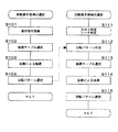
図6は、本発明の実施の形態の表示制御装置の処理を示すフローチャートである。
【0074】
本発明の実施の形態の表示制御装置150における、図柄オブジェクトの変動表示処理は、図柄オブジェクトが移動する変動表示軌道に沿った移動表示態様を決定する移動表示態様選択処理と、図柄オブジェクトの変動表示軌道上における回転表示態様を決定する回転表示態様選択処理とで構成される。以下、移動表示態様選択処理と回転表示態様選択処理とに分けて説明する。
【0075】
移動表示態様選択処理では、表示制御装置150は、遊技制御装置100から送信される表示指令信号を受信する(S101)。そして、受信した表示指令信号に基づいて識別情報の停止態様(大当りであるのか、リーチであるのか、ハズレであるのか)を判定して、移動表示態様を決定するための抽選テーブルを選択して(S102)、識別情報の停止態様と整合する移動表示態様のみが選択されるようにする。例えば、大当りと、ハズレとで異なる変動表示軌道を用いた移動表示をすることによって、遊技者に大当りへの期待感を持たせるような表示演出をする場合である。そして、乱数を用いて抽選テーブルから抽選をして(S103)、この抽選に基づいて、移動表示態様として公転パターンを選択する(S104)。このように、表示制御装置150が、移動表示態様選択処理を実行することによって、移動表示手段として機能する。
【0076】
回転表示態様選択処理では、表示制御装置150は、遊技制御装置100から受信した表示指令信号に基づいて識別情報の停止態様(大当りであるのか、リーチであるのか、ハズレであるのか)を判定し(S111)、移動表示態様選択処理で決定した公転パターンを判定する(S112)。そして、回転表示態様を決定するための抽選テーブルを選択して(S113)、識別情報の停止態様と公転パターンとに整合する回転表示態様のみが選択されるようにする。すなわち、遊技(変動表示ゲーム)の進行によって(例えば、大当りか、ハズレかによって)異なる自転パターンの回転表示をすることによって、遊技者に大当りへの期待感を持たせるような表示演出をする場合や、選択された変動表示軌道との関係で選択できない自転パターンの回転表示を排除する場合である。そして、乱数を用いて抽選テーブルから抽選をして(S114)、この抽選に基づいて、回転表示態様として自転パターンを選択する(S115)。この自転パターンの選択によって、図柄オブジェクトが回転するか否か、図柄オブジェクトの回転軸数、仮停止の態様(回転によって仮停止を実現するか)、図柄オブジェクトが回転停止したときの表示態様、図柄オブジェクトの回転速度等が決定される。このように、表示制御装置150が、回転表示態様選択処理を実行することによって、回転表示手段として機能する。
【0077】
そして、移動表示態様選択処理で選択され決定された公転パターンに基づいて図柄オブジェクトの変動表示軌道に沿った移動表示を行い、回転表示態様選択処理で選択され決定された自転パターンに基づいて図柄オブジェクトの変動表示軌道に上における回転表示を行って、識別情報の変動表示を行う。
【0078】
図7は、識別情報の回転の態様を説明する図である。
【0079】
図7(A)は識別情報に垂直に回転軸が設けられており、図7(B)は識別情報に水平に回転軸が設けられており、図7(C)は識別情報に垂直と水平とに回転軸が設けられている状態を示す。
【0080】
図7(A)において、識別情報は垂直に設けられた回転軸(垂直軸)を中心に水平方向に回転をしている。すなわち、遊技者に正対して表示されている識別情報は、斜め、側面、斜め、裏面(左右反転状態)を含んで順に回転していく。
【0081】
図7(B)において、識別情報は水平に設けられた回転軸(水平軸)を中心に垂直方向に回転をしている。すなわち、遊技者に正対して表示されている識別情報は、手前に倒れるように回転し、上面、裏面(倒立状態)を含んで順に回転していく。
【0082】
図7(C)において、識別情報は、垂直軸と水平軸とを中心に回転をしている。すなわち、遊技者に正対して表示されている識別情報は、左に回転しながら手前に倒れるように回転していく。図7(C)において、識別情報は、識別情報の中央付近で直交する2つの軸(垂直軸と水平軸)を中心に回転しているが、回転軸は、識別情報の中心付近で交わっていなくてもよく、遊技の進行に基づいて軸の交点が移動してもよい。また、図7(C)において、識別情報は2つの軸(垂直軸と水平軸)を中心に回転しているが、回転軸は3本以上であってもよく、遊技の進行に基づいて回転軸数は変化するように構成してもよい。
【0083】
このとき、識別情報は、図12に示すように表面と裏面とで表示態様が異なり、識別情報の表と裏とが区別できるように表示される。すなわち、識別情報が正位置であるか否かが区別できるように表示される。
【0084】
図8には、本発明の実施の形態において変動表示装置4に識別情報が表示される態様を示す。
【0085】
識別情報の変動開始時等の遊技者に識別情報の種類を認識させる必要があるとき(変動表示の態様を見せる必要に乏しいとき)には、変動表示装置4の表示領域(4A)には左、中、右の三つの識別情報が大きく表示されている。そして、変動表示を開始すると、識別情報が軌道(501、502、503)上を下方にスクロールして変動表示を開始する。このとき、軌道(501、502、503)は、表示領域4Aを含んで仮想的に設けられて仮想表示領域(図8に点線で示す)内に設けられており、識別情報は表示領域4Aからはみ出して、変動表示装置4に表示されなくなっても、軌道(501、502、503)上を周回運動をしている。
【0086】
図9には、本発明の実施の形態において変動表示装置4に識別情報が表示される態様を示す。
【0087】
変動表示ゲーム中等の遊技者に識別情報の変化の態様を見せて、遊技者の興趣を高める必要があるとき(識別情報の種類を認識させる必要に乏しいとき)には、変動表示装置4の表示領域(4A)には左、中、右の三つの識別情報が周回運動をする軌道(501、502、503)の全体が表示されている。そして、識別情報は、図4、図5で説明したように、軌道上で正立したままで又は軌道上で回転しながら軌道上を周回運動する。
【0088】
図10には、識別情報の結果態様として各識別情報が未確定な状態の一例を示す。
【0089】
変動表示ゲームが開始され、識別情報が変動表示(軌道に沿った周回運動に基づくスクロール表示)を開始すると、変動表示に伴い識別情報が回転を開始する。図10にあっては、異なる列(左列、中列、右列)の識別情報は同期することなく、様々な向きで変動表示をしているが、異なる列の識別情報を同期させて回転させる変動表示をしてもよい。また、遊技の進行に合わせて、識別情報を同期させて変動表示するかを決定してもよい。
【0090】
図11には、識別情報の結果態様として各識別情報の変動表示が停止して確定した状態(停止図柄となった状態)の一例を示す。
【0091】
変動表示ゲームの結果、識別情報が停止すると、識別情報は、他の識別情報と区別できる態様で表示される正位置で停止する。
【0092】
しかし、識別情報の中には左右対称な形状の識別情報や(例えば「8」)、逆転すると他の識別情報と同一形状になる識別情報(例えば「6」と「9」)があるため、識別情報が正位置であるのかを識別可能に表示する必要がある。このため、識別情報に正位置である旨を認識可能な表示をする。
【0093】
具体的には、 図12(a)に示すように、識別情報が正位置の場合には表示色を変えて識別情報を表示する。すなわち、識別情報が正位置のときに遊技者に見せる面である正面の色を所定の色に定めて、他の面(例えば、裏面)と表示色を変える。この色の変更には、識別情報全体の色の変更の他に、識別情報の一部(例えば枠の色)を変化させることも含まれる。
【0094】
また 図12(b)に示すように、識別情報が正位置の場合には識別情報の予め定めた標識が見えるように識別情報を表示する。すなわち、識別情報が正位置のときに遊技者に見せる面である正面には所定の標識として星印を付加しておき、他の面(例えば、裏面)には星印を付加しない。
【0095】
また 図12(c)に示すように、識別情報が正位置の場合には識別情報の形状を変化させて識別情報を表示する。すなわち、識別情報が正位置のときに遊技者に見せる面である正面が表示されている場合には、識別情報が他の面が表示されているときより少し大きく表示される。また、識別情報の正面が表示されている場合には、識別情報の字体を変更して表示するように構成してもよい。
【0096】
今回開示した実施の形態は、全ての点で例示であって制限的なものではないと考えられるべきである。本発明の範囲は上記した説明ではなくて特許請求の範囲によって示され、特許請求の範囲と均等の意味及び内容の範囲での全ての変更が含まれることが意図される。
【図面の簡単な説明】
【図1】 本発明の実施の形態の遊技機の遊技盤の正面図である。
【図2】 同じく遊技機の制御系の一部を示すブロック図である。
【図3】 同じく遊技機の状態遷移図である。
【図4】 同じく識別情報の配置を示す説明図である。
【図5】 同じく識別情報の別な配置を示す説明図である。
【図6】 同じく表示制御装置の処理を示すフローチャートである。
【図7】 同じく識別情報の回転の態様の説明図である。
【図8】 同じく変動表示装置に識別情報が表示される態様の説明図である。
【図9】 同じく変動表示装置に識別情報が表示される態様の説明図である。
【図10】 同じく識別情報が未確定な状態の説明図である。
【図11】 同じく識別情報が確定した状態の説明図である。
【図12】 同じく識別情報が表示態様の説明図である。
【符号の説明】
1 遊技盤
4 変動表示装置
4A 表示領域
100 遊技制御装置
150 表示制御装置
501、502、503 軌道[0001]
[Technical field to which the invention belongs]
The present invention relates to a gaming machine, and more particularly, to a gaming machine that performs a variable display game in which a plurality of symbol objects (identification information) arranged in a virtual space are variably displayed on a display device.
[0002]
[Prior art]
The game machine has a variable display game for variably displaying a plurality of identification information including specific identification information (special symbols) on a variable display device including a liquid crystal display or the like in accordance with a winning of a game ball launched into the game area. There are those that give a specific game value such as causing a special game state in connection with the display result being in a specific mode.
[0003]
In such a variable display game of a gaming machine, there is known a variable display mode (hereinafter referred to as rotary scroll) in which identification information is switched while rotating a plurality of pieces of identification information arranged on the background.
[0004]
In addition, a gaming machine has been proposed that uses 3DCG (three-dimensional computer graphics) to display identification information, characters, and symbols three-dimensionally to improve the interest of a variable display game.
[0005]
[Problems to be solved by the invention]
However, in order to improve the interest of the variable display game, some of the conventional gaming machines perform three-dimensional background and character display and symbol rotation display. However, the conventional two-dimensional display is an extension of the conventional two-dimensional display. However, there is a problem that the display position and display mode of the symbols in the virtual space set in the variable display device are merely expressed as one of the display effects.
[0006]
An object of the present invention is to realize a variable display game in which a display form of a pattern in a virtual space is not simply an expression form of a display effect while expressing the figure three-dimensionally, and to improve the interest of the game.
[0007]
[Means for Solving the Problems]
The present invention comprises display control means for controlling a variable display game for variable display of a plurality of symbol objects having a surface formed by a frame of identification information in a variable display area of a variable display device, and the result of the variable display game , symbol object the variable display is a frame in which is formed a surface of the identification information that can be distinguished from identification information set in the other symbol objects by confronting the player as the normal position face down, the symbol object In the gaming machine capable of giving a specific game value in relation to the stop result mode, the display control means is configured to display the symbol along a variable display trajectory set in a virtual space provided including the variable display area. A plurality of objects are arranged, and movement display means for moving and displaying the symbol object along the variation display trajectory, and movement display by the movement display means. Rotation display means for rotating and displaying the symbol object, and the rotation display means selects the rotation pattern of the symbol object from a table in which the result mode of the variable display game corresponds to the rotation pattern of the symbol object. The number of rotation axes of the symbol object can be changed in association with the progress of the variable display game, and a predetermined sign indicating that the symbol object is stopped so that the normal position plane faces the player is displayed on the symbol object. It is added to the normal position plane.
[0008]
According to a second invention, in the first invention, the display control means performs rotation display of the symbol object by the rotation display means in a state where the movement display of the symbol object by the movement display means is stopped. The temporary stop state of the identification information can be realized .
[0009]
A third invention is characterized in that, in the first or second invention, the rotation display means can change the rotation speed of the symbol object in association with the progress of the variable display game .
[0014]
Operation and effect of the invention
The present invention includes display control means for controlling a variable display game for variable display of a symbol object having identification information set in the variable display area of the variable display device, and a specific game related to the result mode of the variable display game. In a gaming machine capable of giving value, the display control means arranges the symbol objects along a variable display trajectory set in a virtual space (for example, a virtual three-dimensional space) provided including the variable display area. A moving display means for moving and displaying the symbol object along the variation display trajectory; and a rotation display means for rotating and displaying the symbol object to be moved and displayed by the movement display means. Since the rotation display is performed in association with each other, the display of the variable display game can be varied, and the interest in the game is improved. It is possible. And since identification information is arrange | positioned along a fluctuation | variation display orbit, the order in which a symbol appears can be understood easily. Further, since the rotation display means can change the number of rotation axes of the symbol object in association with the progress of the variable display game, the reliability can be changed depending on the number of rotation axes, and various notices can be displayed. . In addition, since a predetermined sign indicating that the symbol object stops on the surface is added to the normal position surface of the symbol object, the normal display mode can be recognized even if the symbol object rotates. .
[0015]
In the second invention, the display control means realizes the temporary stop state of the identification information by performing the rotation display of the symbol object by the rotation display means while the movement display of the symbol object is stopped by the movement display means. Since it is possible, it is possible to improve the fun of the game by various display of variation.
[0016]
In the third invention, since the rotation display means can change the rotation speed of the symbol object in association with the progress of the variable display game, the reliability can be changed depending on the rotation speed, and more various notices can be displayed. It becomes possible.
[0021]
DETAILED DESCRIPTION OF THE INVENTION
Hereinafter, embodiments of the present invention will be described with reference to the drawings.
[0022]
FIG. 1 is a front view of a gaming board 1 of a gaming machine (pachinko gaming machine) according to an embodiment of the present invention.
[0023]
A game area 3 surrounded by the
[0024]
The display unit of the
[0025]
In the specific display example of the present embodiment to be described later, the symbol object is the identification information itself, but the symbol object may be configured by including a plurality of identification information. For example, a plurality of pieces of identification information may be included in one solid (symbol object) by pasting different pieces of identification information on surfaces that are visible from different directions of the solid.
[0026]
Above the special variable winning
[0027]
A game is played by launching a game ball (pachinko ball) from a hitting ball launching device (not shown) toward the game area 3, and the launched game ball is rolled by a windmill or the like arranged at various locations in the game area 3. The surface of the game area 3 is flowed down while the rolling direction is changed by the
[0028]
When a game ball wins the start opening 7, the general winning
[0029]
When there is a winning game ball at the starting port 7, the
[0030]
The winning of the game ball to the start port 7 is detected by the special
[0031]
The winning of the game ball to the special
[0032]
When there is a winning game ball at the normal
[0033]
The passing of the game ball to the normal
[0034]
At the lowest end of the game area 3, an out port 12 for discharging game balls is provided.
[0035]
A decoration light-emitting device such as a decoration lamp or LED is provided at a key point of the gaming machine. The gaming machine is provided with a sound output device (speaker).
[0036]
FIG. 2 is a block diagram showing a part of the control system of the gaming machine 1 centered on the
[0037]
The
[0038]
The
[0039]
The discharge control device 200 controls the operation of the payout unit based on the prize ball command signal from the
[0040]
The
[0041]
The sound control device 300 controls the output of sound effects from the speakers.
[0042]
Communication from the
[0043]
A power supply device (not shown) of the gaming machine includes a backup power supply unit and a power failure monitoring circuit in addition to the power supply circuit. When the power failure monitoring circuit detects a predetermined voltage drop of the power supply device, the power failure monitoring circuit sequentially outputs a power failure detection signal and a reset signal to the
[0044]
The
[0045]
The
[0046]
The
[0047]
The drawing processing performed by the
[0048]
Note that the
[0049]
In addition, the
[0050]
In front of the
[0051]
FIG. 3 is a state transition diagram of the gaming machine according to the embodiment of the present invention. The outline of the game will be described according to this state transition diagram. In the following description, the variable display area of the variable display game of the
[0052]
First, at the beginning of the game (or before the start of the game), the customer is in a waiting state, and a display command signal for instructing the display of the customer waiting screen is transmitted from the
[0053]
Then, when the game ball launched into the game area 3 wins the start opening 7, a predetermined random number is extracted by the
[0054]
When a predetermined time has elapsed after the start of the fluctuation display, the fluctuation display temporarily stops in the order of left, right, and middle. In this process, the reach state (for example, the left symbol and the right symbol generate a combination of jackpots). A predetermined reach game is performed. In this reach game, for example, the inside symbols are displayed in a variably displayed state at a very low speed, variably displayed at a high speed, or the variably displayed state is reversed. In addition, background display and character display in accordance with the reach game are performed.
[0055]
The temporary stop state is a state in which the final stop symbol is not determined as a substantially stop state in which the player can recognize the symbol. Specifically, in addition to slightly changing the symbol at the stop position, modes such as rotating the symbol, scaling the symbol, changing the symbol color, changing the symbol shape, etc. There is.
[0056]
If the winning symbol lottery result is a big hit, the left, right and middle symbols are finally stopped in a predetermined combination of big hits, and a big hit occurs.
[0057]
When this big hit game is generated, a special game is performed in which the special
[0058]
In this case, if the jackpot is a specific jackpot, a specific gaming state is generated after the jackpot game, and the probability of the next jackpot occurrence is increased (probability variation state), or the fluctuation display time of the usual variable display game is shortened (Time reduction) etc. are performed, and it becomes a more advantageous state for the player.
[0059]
Then, if there is a special symbol start memory when the variable display game is finished (when lost) or when the big hit game is finished, a new variable display game is repeated based on the special symbol start memory. Further, when the variable display game is finished (when it is lost), if there is no special symbol start memory, it is returned to the customer waiting state.
[0060]
When the game ball passes through the normal
[0061]
FIG. 4 shows the arrangement of identification information in the embodiment of the present invention.
[0062]
The numbers from “0” to “9” as identification information (symbol objects) are sequentially arranged on a
[0063]
In the example shown in FIG. 4, control is performed so that the identification information on the near side (501A) is large and the identification information on the rear side (501B) is displayed small in the trajectory. The size of the identification information is controlled so as to be displayed three-dimensionally.
[0064]
FIG. 5 shows another arrangement of the identification information in the embodiment of the present invention.
[0065]
The numbers “0” to “9”, which are identification information constituting the symbol object, are sequentially arranged on a
[0066]
At this time, the identification information may be rotated with a certain relationship, such as rotating in synchronization with the orbital motion on the orbit. For example, the identification information is rotated five times for one rotation on the track. The number of rotations of the identification information may be determined in relation to the number of identification information arranged along the trajectory.
[0067]
Also, the number of rotations of the identification information can be changed according to the progress of the game. That is, it is possible to produce effects such as changing the rotation speed of the identification information according to the contents of the variable display game that is developed thereafter. In other words, when the identification information rotates at a high speed, the reliability to reach is improved, and when the identification information rotates in a complicated (multi-axis) manner, the reliability to the big hit is improved. More specifically, when a plurality of rotation axes of the symbol object are set, the rotation display by each axis may have a different meaning. For example, three X-axis, Y-axis, and Z-axis orthogonal to each other are provided in the symbol object, and the X-axis rotation is configured as a reach notice, the Y-axis rotation as a jackpot notice, and the Z-axis rotation as a jackpot confirmation. Further, the rotation display by each axis may have different reliability as different meanings. For example, in the X, Y, and Z axes provided in the symbol object, the big hit reliability is 10% when the X axis is rotated, the big hit reliability is 20% when the Y axis is rotated, and the big hit reliability is obtained when the Z axis is rotated. Set to 30%. Further, the synthesized rotation by a plurality of axes may have different meanings (reliability). That is, the big hit reliability is set to 50% when the combined rotation of the X-axis rotation and the Y-axis rotation is set, and the big hit reliability is set to 100% when the combined rotation of the X-axis rotation, the Y-axis rotation and the Z-axis rotation is set. To do.
[0068]
In the example shown in FIG. 5, the temporary stop state of the identification information can be expressed by rotation of the identification information. That is, even if the scrolling display of the identification information is stopped, if the identification information is rotated and displayed, it represents that the identification information is in a temporarily stopped state, not a confirmed state.
[0069]
In the example shown in FIG. 5, the identification information is displayed upright on the near side (501A) of the track. That is, before the track, the identification information is displayed in a normal display mode, and the player can read the meaning of the identification information.
[0070]
In the examples shown in FIGS. 4 and 5, the trajectory is an oval shape that is a closed figure, but may be an open figure (for example, a parabola). In this case, the identification information is displayed so small that the player cannot recognize it at the end of the track, appears small from the other end of the track, and makes a circular motion toward the front.
[0071]
In the example shown in FIGS. 4 and 5, the symbol object is the identification information itself, but the symbol object may be configured by including a plurality of identification information. For example, a plurality of pieces of identification information having the same meaning may be pasted on a surface that can be seen from different directions in a solid, and the plurality of pieces of identification information may be included in one solid (symbol object). In this way, if the symbol object is configured so that the identification information can be recognized from any direction, the changing identification information can always be recognized even when the symbol object is rotating. Can be improved.
[0072]
Further, different identification information may be pasted on surfaces (plane, curved surface) that can be seen from different directions of a solid so that a plurality of identification information is included in one solid (symbol object). If the symbol object is configured to have identification information having different meanings in this way, it is possible to display the variation of the identification information in both the rotation of the symbol object and the movement of the symbol object in the orbit. It is possible to display a complicated variation display and improve the interest of the variation display effect. The surface formed by the solid constituting the symbol object described above may be a flat surface or a curved surface.
[0073]
FIG. 6 is a flowchart showing processing of the display control apparatus according to the embodiment of the present invention.
[0074]
In the
[0075]
In the moving display mode selection process, the
[0076]
In the rotation display mode selection process, the
[0077]
Then, based on the revolution pattern selected and determined in the movement display mode selection process, the movement display along the variation display trajectory of the symbol object is performed, and the pattern object is selected based on the rotation pattern selected and determined in the rotation display mode selection process. Rotation display is performed on the fluctuation display trajectory, and identification information is displayed in a variable manner.
[0078]
FIG. 7 is a diagram for explaining how the identification information is rotated.
[0079]
7A, a rotation axis is provided perpendicular to the identification information, FIG. 7B is provided with a rotation axis horizontally in the identification information, and FIG. 7C is vertical and horizontal to the identification information. And shows a state in which a rotating shaft is provided.
[0080]
In FIG. 7A, the identification information rotates in the horizontal direction around a rotation axis (vertical axis) provided vertically. That is, the identification information displayed facing the player is rotated in order including the diagonal, the side, the diagonal, and the back (left-right inverted state).
[0081]
In FIG. 7B, the identification information rotates in the vertical direction around a horizontal rotation axis (horizontal axis). That is, the identification information displayed facing the player is rotated so as to fall forward, and in turn includes the upper surface and the back surface (inverted state).
[0082]
In FIG. 7C, the identification information rotates about the vertical axis and the horizontal axis. That is, the identification information displayed facing the player is rotated so as to fall forward while rotating counterclockwise. In FIG. 7C, the identification information rotates around two orthogonal axes (vertical axis and horizontal axis) near the center of the identification information, but the rotation axes intersect near the center of the identification information. The intersection of the axes may be moved based on the progress of the game. In FIG. 7C, the identification information rotates about two axes (vertical axis and horizontal axis). However, the number of rotation axes may be three or more and rotates based on the progress of the game. The number of axes may be configured to change.
[0083]
At this time, the identification information is displayed so that the display mode is different between the front surface and the back surface as shown in FIG. That is, it is displayed so that it can be distinguished whether or not the identification information is the normal position.
[0084]
In FIG. 8, the aspect by which identification information is displayed on the fluctuation |
[0085]
When it is necessary to make the player recognize the type of identification information at the start of variation of the identification information (when it is not necessary to show the variation display mode), the display area (4A) of the
[0086]
In FIG. 9, the aspect by which identification information is displayed on the fluctuation |
[0087]
When it is necessary to show the player how to change the identification information during a variable display game or the like and to enhance the player's interest (when it is not necessary to recognize the type of identification information), the display of the
[0088]
FIG. 10 shows an example of a state in which each piece of identification information is undetermined as a result mode of the identification information.
[0089]
When the variable display game is started and the identification information starts variable display (scroll display based on the orbital motion along the trajectory), the identification information starts rotating along with the variable display. In FIG. 10, the identification information of different columns (left column, middle column, right column) is displayed in a variable manner in various directions without being synchronized, but the identification information of different columns is rotated in synchronization. It is also possible to display variable display. In addition, according to the progress of the game, whether to display the identification information in a synchronized manner may be determined.
[0090]
FIG. 11 shows an example of a state in which the variation display of each piece of identification information is stopped and confirmed (a state in which it has become a stop symbol) as a result mode of the identification information.
[0091]
When the identification information stops as a result of the variable display game, the identification information stops at the normal position displayed in a manner that can be distinguished from other identification information.
[0092]
However, in the identification information, there is identification information having a symmetrical shape (for example, “8”), and identification information (for example, “6” and “9”) having the same shape as other identification information when reversed. It is necessary to display whether or not the identification information is the correct position so that it can be identified. For this reason, the identification information is displayed so that it can be recognized as the correct position.
[0093]
Specifically, as shown in FIG. 12A, when the identification information is in the normal position, the identification information is displayed by changing the display color. That is, the front color, which is the surface that is shown to the player when the identification information is in the normal position, is set to a predetermined color, and the display color is changed from the other surface (for example, the back surface). This color change includes changing part of the identification information (for example, the color of the frame) in addition to changing the color of the entire identification information.
[0094]
Further, as shown in FIG. 12B, when the identification information is in the normal position, the identification information is displayed so that a predetermined sign of the identification information can be seen. That is, an asterisk is added as a predetermined sign on the front surface, which is the surface that the player can see when the identification information is in the normal position, and no asterisk is added on the other surface (for example, the back surface).
[0095]
Further, as shown in FIG. 12C, when the identification information is in the normal position, the identification information is displayed by changing the shape of the identification information. That is, when the front surface, which is the surface that the player can see when the identification information is in the normal position, is displayed, the identification information is displayed slightly larger than when the other surface is displayed. Moreover, when the front of identification information is displayed, you may comprise so that the font of identification information may be changed and displayed.
[0096]
The embodiment disclosed this time should be considered as illustrative in all points and not restrictive. The scope of the present invention is defined by the terms of the claims, rather than the description above, and is intended to include any modifications within the scope and meaning equivalent to the terms of the claims.
[Brief description of the drawings]
FIG. 1 is a front view of a game board of a gaming machine according to an embodiment of the present invention.
FIG. 2 is a block diagram showing a part of the control system of the gaming machine.
FIG. 3 is also a state transition diagram of the gaming machine.
FIG. 4 is an explanatory view showing the arrangement of identification information.
FIG. 5 is an explanatory view showing another arrangement of identification information.
FIG. 6 is a flowchart showing processing of the display control apparatus.
FIG. 7 is also an explanatory diagram of a mode of rotation of identification information.
FIG. 8 is an explanatory diagram of a mode in which identification information is similarly displayed on the variable display device.
FIG. 9 is an explanatory diagram of a mode in which identification information is similarly displayed on the variable display device.
FIG. 10 is an explanatory diagram of a state where identification information is still uncertain.
FIG. 11 is an explanatory diagram of a state in which identification information is also confirmed.
FIG. 12 is an explanatory diagram of how the identification information is similarly displayed.
[Explanation of symbols]
DESCRIPTION OF SYMBOLS 1
Claims (1)
前記表示制御手段は、
前記変動表示領域を含んで設けられた仮想空間内に設定された変動表示軌道に沿って前記図柄オブジェクトを複数配置して、前記変動表示軌道に沿って前記図柄オブジェクトを移動表示させる移動表示手段と、
前記移動表示手段によって移動表示する前記図柄オブジェクトを回転表示させる回転表示手段と、を備え、
前記回転表示手段は、前記変動表示ゲームの結果態様と前記図柄オブジェクトの自転パターンとが対応したテーブルから図柄オブジェクトの自転パターンを選択することによって、変動表示ゲームの進行に関連付けて図柄オブジェクトの回転軸数を変更可能とし、
前記正位置面が遊技者に正対するように前記図柄オブジェクトが停止することを示す所定の標識を前記図柄オブジェクトの正位置面に付加したことを特徴とする遊技機。Display control means for controlling a variable display game for variable display of a plurality of symbol objects having a surface formed by a frame of identification information in the variable display area of the variable display device, and as a result of the variable display game, the variable display symbol object is a frame in which is formed a surface of the identification information that can be distinguished from identification information set in the other symbol objects by confronting the player as the normal position face down, to stop the result aspects of the design object In a gaming machine that can be given a specific gaming value in relation,
The display control means includes
Moving display means for arranging a plurality of the symbol objects along a variable display trajectory set in a virtual space provided including the variable display region, and for moving and displaying the symbol objects along the variable display trajectory; ,
Rotation display means for rotating and displaying the symbol object moved and displayed by the movement display means,
The rotation display means selects the rotation pattern of the symbol object from a table in which the result mode of the variation display game and the rotation pattern of the symbol object correspond to each other, thereby rotating the rotation axis of the symbol object in association with the progress of the variation display game. The number can be changed,
A gaming machine, wherein a predetermined sign indicating that the symbol object is stopped is added to the regular position surface of the symbol object so that the regular position surface faces the player.
Priority Applications (1)
| Application Number | Priority Date | Filing Date | Title |
|---|---|---|---|
| JP2001258939A JP4464016B2 (en) | 2001-08-29 | 2001-08-29 | Game machine |
Applications Claiming Priority (1)
| Application Number | Priority Date | Filing Date | Title |
|---|---|---|---|
| JP2001258939A JP4464016B2 (en) | 2001-08-29 | 2001-08-29 | Game machine |
Publications (3)
| Publication Number | Publication Date |
|---|---|
| JP2003062237A JP2003062237A (en) | 2003-03-04 |
| JP2003062237A5 JP2003062237A5 (en) | 2005-07-14 |
| JP4464016B2 true JP4464016B2 (en) | 2010-05-19 |
Family
ID=19086379
Family Applications (1)
| Application Number | Title | Priority Date | Filing Date |
|---|---|---|---|
| JP2001258939A Expired - Fee Related JP4464016B2 (en) | 2001-08-29 | 2001-08-29 | Game machine |
Country Status (1)
| Country | Link |
|---|---|
| JP (1) | JP4464016B2 (en) |
Families Citing this family (1)
| Publication number | Priority date | Publication date | Assignee | Title |
|---|---|---|---|---|
| JP2018126244A (en) * | 2017-02-07 | 2018-08-16 | 株式会社ソフイア | Game machine |
-
2001
- 2001-08-29 JP JP2001258939A patent/JP4464016B2/en not_active Expired - Fee Related
Also Published As
| Publication number | Publication date |
|---|---|
| JP2003062237A (en) | 2003-03-04 |
Similar Documents
| Publication | Publication Date | Title |
|---|---|---|
| JP2003126438A (en) | Game machine | |
| JP4294890B2 (en) | Game machine | |
| JP4086588B2 (en) | Game machine | |
| JP4953259B1 (en) | Slot machine | |
| JP4323145B2 (en) | Game machine | |
| JP2004073294A (en) | Game machine | |
| JP4456783B2 (en) | Game machine | |
| JP4464016B2 (en) | Game machine | |
| JP3623487B2 (en) | Game machine | |
| JP2003000869A (en) | Game machine | |
| JP2003135771A (en) | Game machine | |
| JP2002336462A (en) | Game machine | |
| JP4388257B2 (en) | Game machine | |
| JP2003126452A (en) | Game machine | |
| JP4184646B2 (en) | Game machine | |
| JP4554858B2 (en) | Game machine | |
| JP4615157B2 (en) | Game machine | |
| JP2003117144A (en) | Game machine | |
| JP2003199912A (en) | Game machine, picture display controller for the same, and game picture display control program | |
| JP2003062238A (en) | Game machine | |
| JP2003117146A (en) | Game machine | |
| JP3930717B2 (en) | Game machine | |
| JP2003135751A (en) | Game machine | |
| JP4202628B2 (en) | Game machine | |
| JP2003033492A (en) | Game machine |
Legal Events
| Date | Code | Title | Description |
|---|---|---|---|
| A521 | Written amendment |
Free format text: JAPANESE INTERMEDIATE CODE: A523 Effective date: 20041124 |
|
| A621 | Written request for application examination |
Free format text: JAPANESE INTERMEDIATE CODE: A621 Effective date: 20041124 |
|
| A977 | Report on retrieval |
Free format text: JAPANESE INTERMEDIATE CODE: A971007 Effective date: 20071122 |
|
| A131 | Notification of reasons for refusal |
Free format text: JAPANESE INTERMEDIATE CODE: A131 Effective date: 20080108 |
|
| A521 | Written amendment |
Free format text: JAPANESE INTERMEDIATE CODE: A523 Effective date: 20080305 |
|
| A02 | Decision of refusal |
Free format text: JAPANESE INTERMEDIATE CODE: A02 Effective date: 20080708 |
|
| A521 | Written amendment |
Free format text: JAPANESE INTERMEDIATE CODE: A523 Effective date: 20080821 |
|
| A911 | Transfer of reconsideration by examiner before appeal (zenchi) |
Free format text: JAPANESE INTERMEDIATE CODE: A911 Effective date: 20080916 |
|
| A912 | Removal of reconsideration by examiner before appeal (zenchi) |
Free format text: JAPANESE INTERMEDIATE CODE: A912 Effective date: 20081031 |
|
| A01 | Written decision to grant a patent or to grant a registration (utility model) |
Free format text: JAPANESE INTERMEDIATE CODE: A01 |
|
| A61 | First payment of annual fees (during grant procedure) |
Free format text: JAPANESE INTERMEDIATE CODE: A61 Effective date: 20100218 |
|
| FPAY | Renewal fee payment (event date is renewal date of database) |
Free format text: PAYMENT UNTIL: 20130226 Year of fee payment: 3 |
|
| R150 | Certificate of patent or registration of utility model |
Free format text: JAPANESE INTERMEDIATE CODE: R150 Ref document number: 4464016 Country of ref document: JP Free format text: JAPANESE INTERMEDIATE CODE: R150 |
|
| FPAY | Renewal fee payment (event date is renewal date of database) |
Free format text: PAYMENT UNTIL: 20130226 Year of fee payment: 3 |
|
| FPAY | Renewal fee payment (event date is renewal date of database) |
Free format text: PAYMENT UNTIL: 20130226 Year of fee payment: 3 |
|
| FPAY | Renewal fee payment (event date is renewal date of database) |
Free format text: PAYMENT UNTIL: 20130226 Year of fee payment: 3 |
|
| FPAY | Renewal fee payment (event date is renewal date of database) |
Free format text: PAYMENT UNTIL: 20130226 Year of fee payment: 3 |
|
| FPAY | Renewal fee payment (event date is renewal date of database) |
Free format text: PAYMENT UNTIL: 20140226 Year of fee payment: 4 |
|
| R250 | Receipt of annual fees |
Free format text: JAPANESE INTERMEDIATE CODE: R250 |
|
| R250 | Receipt of annual fees |
Free format text: JAPANESE INTERMEDIATE CODE: R250 |
|
| R250 | Receipt of annual fees |
Free format text: JAPANESE INTERMEDIATE CODE: R250 |
|
| R250 | Receipt of annual fees |
Free format text: JAPANESE INTERMEDIATE CODE: R250 |
|
| R250 | Receipt of annual fees |
Free format text: JAPANESE INTERMEDIATE CODE: R250 |
|
| R250 | Receipt of annual fees |
Free format text: JAPANESE INTERMEDIATE CODE: R250 |
|
| LAPS | Cancellation because of no payment of annual fees |