JP4391981B2 - 射出成形機用金型移動機構 - Google Patents
射出成形機用金型移動機構 Download PDFInfo
- Publication number
- JP4391981B2 JP4391981B2 JP2005327868A JP2005327868A JP4391981B2 JP 4391981 B2 JP4391981 B2 JP 4391981B2 JP 2005327868 A JP2005327868 A JP 2005327868A JP 2005327868 A JP2005327868 A JP 2005327868A JP 4391981 B2 JP4391981 B2 JP 4391981B2
- Authority
- JP
- Japan
- Prior art keywords
- mold
- support plate
- plate
- clamping
- movable
- Prior art date
- Legal status (The legal status is an assumption and is not a legal conclusion. Google has not performed a legal analysis and makes no representation as to the accuracy of the status listed.)
- Expired - Fee Related
Links
- 238000001746 injection moulding Methods 0.000 title claims description 20
- 238000002347 injection Methods 0.000 claims description 7
- 239000007924 injection Substances 0.000 claims description 7
- 239000011347 resin Substances 0.000 claims description 3
- 229920005989 resin Polymers 0.000 claims description 3
- 238000000465 moulding Methods 0.000 claims 1
- 238000000034 method Methods 0.000 description 8
- 238000010586 diagram Methods 0.000 description 5
- 238000005452 bending Methods 0.000 description 4
- 239000002184 metal Substances 0.000 description 2
- 230000002411 adverse Effects 0.000 description 1
- 230000006835 compression Effects 0.000 description 1
- 238000007906 compression Methods 0.000 description 1
- 230000000694 effects Effects 0.000 description 1
- 238000005516 engineering process Methods 0.000 description 1
- 238000001125 extrusion Methods 0.000 description 1
- 238000004519 manufacturing process Methods 0.000 description 1
- 239000000203 mixture Substances 0.000 description 1
Images


Landscapes
- Moulds For Moulding Plastics Or The Like (AREA)
- Injection Moulding Of Plastics Or The Like (AREA)
Description
生産性を高める手法の一つに、固定型1個当たり可動型を2個準備し、一方の可動型で型締工程及び射出工程を実施している間に他方の可動型で製品取出し工程を実施する手法がある。この場合、2個の可動型は金型移動機構を用いて交互に固定型に臨ませる。
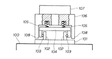
図8は従来の技術の基本構成を説明する図であり、機台100に取付けたベースプレート101にガイドレール102、102を敷設し、これらのガイドレール102、102にベアリング103、103を介してテーブル受台104を取付ける。これで、テーブル受台104を、図面表裏方向に移動させることができる。
スライドテーブル106は、門型断面構造体であり、左右の脚部108、108の下端がベースプレート101から離れているため、テーブル受台104とスライドテーブル106と固定型107を一括して、図面表裏方向に移動させることができる。
この金型移動機構(30)は、型締時に金型を支えるために配置する剛体板(35)と、型締直交方向へ延ばした長尺ベース板(36)と、この長尺ベース板(36)に設けたレール(37)と、このレール(37)に移動可能に取付ける移動体(38)と、この移動体(38)にピン(39)を介して型締方向に移動可能に取付ける金型支持板(41)と、この金型支持板(41)を移動体(38)から離すように押出す弾性部材(58)と、前記金型支持板(41)を型締直交方向へ移動させる移動手段(42)と、この移動手段(42)で移動する金型支持板(41)を案内するために前記剛体板(35)に設けるガイド部材(43)とからなり、
このガイド部材(43)は、前記金型支持板(41)が型締方向に一定量(B−A)移動することを許容する部材であり、
型締力で剛体板(35)に金型支持板(41)が密着したときに、前記移動体(38)と金型支持板(41)との間に隙間(C)が確保されていることを特徴とする。
なお、型締力で剛体板に金型支持板が密着したときであっても移動体と金型支持板との間に隙間が確保できるため、型締力がレールに加わる心配はない。
したがって、請求項1によれば、金型支持板を薄くすることができると共に金型支持板の撓みを無くすことができる金型移動機構を提供することができる。
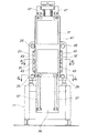
図1は本発明に係る金型移動機構を備えた射出成形機の正面図であり、射出成形機10は、機台11に載せた型締装置20と、この型締装置20で型締した金型21へ溶融樹脂を射出する射出装置22とを基本要素とする。
図3で金型移動機構30の構成を説明すると、金型移動機構30は、型締時に型締力を受けさせる剛体板35と、型締直交方向へ延ばした長尺ベース板36と、この長尺ベース板36に設けたレール37、37と、レール37、37に移動可能に取付ける移動体38、38と、各々の移動体38、38にピン39・・・を介して図面表裏方向へ移動可能に取付ける金型支持板41と、この金型支持板41を移動させる移動手段42と、この移動手段42で移動する金型支持板41を案内するために剛体板35に設けるガイド部材43・・・とからなる。金型支持板41に付した符号57・・・、符号59・・・については別図で説明する。
しかし、穴57、57を凹部に変更して蓋59、59を省略することは差し支えない。
これらの溝64、64で金型支持板41が図面下方へ過剰に移動することを防止することができる。
しかし、長尺ベース板36を上下に分割し、レール37の本数を上2本、下2本、合計4本にすることは差し支えない。
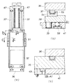
図6は本発明に係る非型締時における作用説明図である。
(a)はボールねじ軸47、47を回すことで、第1可動型31及び第2可動型32を支える金型支持板41が下降している途中の状態を示す。
(a)では、ボールねじ軸47、47を回すことで、第1可動型31が型締位置に到達し、且つ型締状態になったとする。
先に、(a)のc−c線断面図である(c)において、型締力で金型支持板41が図下から上へ一定量(B−A)だけ移動し、剛体板35に密着したことを示す。型締力は剛体板35及び長尺ベース板36に伝達する。
ベアリング53に過大な力が加わらないため、ベアリング53の小径化及び長寿命化が達成できる。
第1に、図7(c)に示すとおり、型締時に、剛体板35へ金型支持板41を面の形態で支承させる。この結果、型締力で金型支持板41が撓む心配はなく、金型支持板41を薄くすることができる。
Claims (2)
- 固定盤(24)に可動盤(27)を接近させることで金型(21)の型締を行う型締装置(20)、及び型締した金型(21)へ溶融樹脂を射出する射出装置(22)を、基本要素とする射出成形機(10)に付設する機構であり、前記金型を構成する固定型(33)と可動型(32)のうちの一方を、型締方向に直交する方向である型締直交方向へ移動させる射出成形機用金型移動機構(30)において、
この金型移動機構(30)は、型締時に金型を支えるために配置する剛体板(35)と、型締直交方向へ延ばした長尺ベース板(36)と、この長尺ベース板(36)に設けたレール(37)と、このレール(37)に移動可能に取付ける移動体(38)と、この移動体(38)にピン(39)を介して型締方向に移動可能に取付ける金型支持板(41)と、この金型支持板(41)を移動体(38)から離すように押出す弾性部材(58)と、前記金型支持板(41)を型締直交方向へ移動させる移動手段(42)と、この移動手段(42)で移動する金型支持板(41)を案内するために前記剛体板(35)に設けるガイド部材(43)とからなり、
このガイド部材(43)は、前記金型支持板(41)が型締方向に一定量(B−A)移動することを許容する部材であり、
型締力で剛体板(35)に金型支持板(41)が密着したときに、前記移動体(38)と金型支持板(41)との間に隙間(C)が確保されていることを特徴とする射出成形機用金型移動機構。 - 前記金型支持板(41)を型締直交方向へ移動させる移動手段(42)は、互いに平行に配置する2本のボールねじ軸を基本要素とすることを特徴とする請求項1記載の射出成形機用金型移動機構。
Priority Applications (1)
| Application Number | Priority Date | Filing Date | Title |
|---|---|---|---|
| JP2005327868A JP4391981B2 (ja) | 2005-11-11 | 2005-11-11 | 射出成形機用金型移動機構 |
Applications Claiming Priority (1)
| Application Number | Priority Date | Filing Date | Title |
|---|---|---|---|
| JP2005327868A JP4391981B2 (ja) | 2005-11-11 | 2005-11-11 | 射出成形機用金型移動機構 |
Publications (2)
| Publication Number | Publication Date |
|---|---|
| JP2007130940A JP2007130940A (ja) | 2007-05-31 |
| JP4391981B2 true JP4391981B2 (ja) | 2009-12-24 |
Family
ID=38152988
Family Applications (1)
| Application Number | Title | Priority Date | Filing Date |
|---|---|---|---|
| JP2005327868A Expired - Fee Related JP4391981B2 (ja) | 2005-11-11 | 2005-11-11 | 射出成形機用金型移動機構 |
Country Status (1)
| Country | Link |
|---|---|
| JP (1) | JP4391981B2 (ja) |
Families Citing this family (4)
| Publication number | Priority date | Publication date | Assignee | Title |
|---|---|---|---|---|
| JP4676548B2 (ja) | 2009-09-02 | 2011-04-27 | ファナック株式会社 | 射出成形機の可動プラテン支持機構 |
| US12564990B2 (en) | 2020-02-06 | 2026-03-03 | Lego A/S | Main guide rail with internal track |
| EP4100226B1 (en) | 2020-02-06 | 2023-11-01 | Lego A/S | Bearing for liniear guide rail |
| JP7564040B2 (ja) | 2021-03-26 | 2024-10-08 | 住友重機械工業株式会社 | 射出成形機 |
-
2005
- 2005-11-11 JP JP2005327868A patent/JP4391981B2/ja not_active Expired - Fee Related
Also Published As
| Publication number | Publication date |
|---|---|
| JP2007130940A (ja) | 2007-05-31 |
Similar Documents
| Publication | Publication Date | Title |
|---|---|---|
| JP4169354B2 (ja) | 射出成形機の型締装置 | |
| JP5607776B2 (ja) | 射出成形機の型締装置 | |
| KR102180308B1 (ko) | 금형 반송용 롤러 유닛 | |
| JP2014208435A (ja) | 射出成形機のトグル式型締機構 | |
| JP2010089295A (ja) | 射出成形機の横型型締装置 | |
| JP4750195B2 (ja) | ノズルタッチ機構部を備えた射出成形機 | |
| US20210394412A1 (en) | Movable platen, opening/closing apparatus and molding apparatus | |
| JP4288627B1 (ja) | 射出成形機の型締装置 | |
| JP4391981B2 (ja) | 射出成形機用金型移動機構 | |
| JP4714705B2 (ja) | 射出成形機の型締装置 | |
| JP4169353B2 (ja) | 射出成形機の型締装置 | |
| JP6756795B2 (ja) | 射出成形機の型締装置 | |
| US20150099030A1 (en) | Die clamping apparatus of injection molding machine with platen adjustment mechanism | |
| JP3635220B2 (ja) | 射出成形機 | |
| JP3964848B2 (ja) | 竪型型締機構 | |
| CN102029326A (zh) | 折床模具固定结构 | |
| JP4288626B1 (ja) | 射出成形機の型締装置 | |
| JP3179019B2 (ja) | 精密射出成形機の型締装置 | |
| JP6616385B2 (ja) | 射出成形機の機台 | |
| JP4270327B1 (ja) | 射出成形機の型締装置 | |
| CN224144042U (zh) | 一种手机零部件加工用定位载具 | |
| CN221968819U (zh) | 一种汽车塑料件注塑合模导向结构 | |
| CN215966238U (zh) | 一种定位精准的模架 | |
| CN2900137Y (zh) | 高精度肘杆式锁模装置 | |
| CN210552641U (zh) | 一种塑料注塑模架 |
Legal Events
| Date | Code | Title | Description |
|---|---|---|---|
| A621 | Written request for application examination |
Free format text: JAPANESE INTERMEDIATE CODE: A621 Effective date: 20070409 |
|
| A977 | Report on retrieval |
Free format text: JAPANESE INTERMEDIATE CODE: A971007 Effective date: 20090721 |
|
| A131 | Notification of reasons for refusal |
Free format text: JAPANESE INTERMEDIATE CODE: A131 Effective date: 20090805 |
|
| A521 | Request for written amendment filed |
Free format text: JAPANESE INTERMEDIATE CODE: A523 Effective date: 20090827 |
|
| TRDD | Decision of grant or rejection written | ||
| A01 | Written decision to grant a patent or to grant a registration (utility model) |
Free format text: JAPANESE INTERMEDIATE CODE: A01 Effective date: 20091006 |
|
| A01 | Written decision to grant a patent or to grant a registration (utility model) |
Free format text: JAPANESE INTERMEDIATE CODE: A01 |
|
| A61 | First payment of annual fees (during grant procedure) |
Free format text: JAPANESE INTERMEDIATE CODE: A61 Effective date: 20091008 |
|
| FPAY | Renewal fee payment (event date is renewal date of database) |
Free format text: PAYMENT UNTIL: 20121016 Year of fee payment: 3 |
|
| R150 | Certificate of patent or registration of utility model |
Ref document number: 4391981 Country of ref document: JP Free format text: JAPANESE INTERMEDIATE CODE: R150 |
|
| FPAY | Renewal fee payment (event date is renewal date of database) |
Free format text: PAYMENT UNTIL: 20121016 Year of fee payment: 3 |
|
| FPAY | Renewal fee payment (event date is renewal date of database) |
Free format text: PAYMENT UNTIL: 20151016 Year of fee payment: 6 |
|
| R250 | Receipt of annual fees |
Free format text: JAPANESE INTERMEDIATE CODE: R250 |
|
| R250 | Receipt of annual fees |
Free format text: JAPANESE INTERMEDIATE CODE: R250 |
|
| R250 | Receipt of annual fees |
Free format text: JAPANESE INTERMEDIATE CODE: R250 |
|
| R250 | Receipt of annual fees |
Free format text: JAPANESE INTERMEDIATE CODE: R250 |
|
| LAPS | Cancellation because of no payment of annual fees |