EP4100226B1 - Bearing for liniear guide rail - Google Patents
Bearing for liniear guide rail Download PDFInfo
- Publication number
- EP4100226B1 EP4100226B1 EP21704238.1A EP21704238A EP4100226B1 EP 4100226 B1 EP4100226 B1 EP 4100226B1 EP 21704238 A EP21704238 A EP 21704238A EP 4100226 B1 EP4100226 B1 EP 4100226B1
- Authority
- EP
- European Patent Office
- Prior art keywords
- bearing
- guide rail
- bearing element
- mould
- mould plate
- Prior art date
- Legal status (The legal status is an assumption and is not a legal conclusion. Google has not performed a legal analysis and makes no representation as to the accuracy of the status listed.)
- Active
Links
- 238000001746 injection moulding Methods 0.000 claims description 48
- 238000002347 injection Methods 0.000 claims description 17
- 239000007924 injection Substances 0.000 claims description 17
- 238000000926 separation method Methods 0.000 claims description 15
- 229920003023 plastic Polymers 0.000 description 9
- 239000000463 material Substances 0.000 description 7
- 239000011800 void material Substances 0.000 description 6
- 238000004519 manufacturing process Methods 0.000 description 5
- 238000003801 milling Methods 0.000 description 5
- 239000000654 additive Substances 0.000 description 4
- 230000000996 additive effect Effects 0.000 description 4
- 229920000426 Microplastic Polymers 0.000 description 3
- 238000009826 distribution Methods 0.000 description 3
- 230000013011 mating Effects 0.000 description 3
- 238000000465 moulding Methods 0.000 description 3
- 238000010276 construction Methods 0.000 description 2
- 230000003292 diminished effect Effects 0.000 description 2
- 238000010438 heat treatment Methods 0.000 description 2
- 230000001788 irregular Effects 0.000 description 2
- 238000000034 method Methods 0.000 description 2
- 230000009286 beneficial effect Effects 0.000 description 1
- 230000000694 effects Effects 0.000 description 1
- 238000000605 extraction Methods 0.000 description 1
- 239000012530 fluid Substances 0.000 description 1
- 238000003825 pressing Methods 0.000 description 1
- 238000007493 shaping process Methods 0.000 description 1
- 239000007787 solid Substances 0.000 description 1
- 230000003068 static effect Effects 0.000 description 1
Images


Classifications
-
- F—MECHANICAL ENGINEERING; LIGHTING; HEATING; WEAPONS; BLASTING
- F16—ENGINEERING ELEMENTS AND UNITS; GENERAL MEASURES FOR PRODUCING AND MAINTAINING EFFECTIVE FUNCTIONING OF MACHINES OR INSTALLATIONS; THERMAL INSULATION IN GENERAL
- F16C—SHAFTS; FLEXIBLE SHAFTS; ELEMENTS OR CRANKSHAFT MECHANISMS; ROTARY BODIES OTHER THAN GEARING ELEMENTS; BEARINGS
- F16C29/00—Bearings for parts moving only linearly
- F16C29/02—Sliding-contact bearings
-
- B—PERFORMING OPERATIONS; TRANSPORTING
- B29—WORKING OF PLASTICS; WORKING OF SUBSTANCES IN A PLASTIC STATE IN GENERAL
- B29C—SHAPING OR JOINING OF PLASTICS; SHAPING OF MATERIAL IN A PLASTIC STATE, NOT OTHERWISE PROVIDED FOR; AFTER-TREATMENT OF THE SHAPED PRODUCTS, e.g. REPAIRING
- B29C45/00—Injection moulding, i.e. forcing the required volume of moulding material through a nozzle into a closed mould; Apparatus therefor
- B29C45/17—Component parts, details or accessories; Auxiliary operations
- B29C45/26—Moulds
- B29C45/2602—Mould construction elements
- B29C45/2606—Guiding or centering means
-
- B—PERFORMING OPERATIONS; TRANSPORTING
- B29—WORKING OF PLASTICS; WORKING OF SUBSTANCES IN A PLASTIC STATE IN GENERAL
- B29C—SHAPING OR JOINING OF PLASTICS; SHAPING OF MATERIAL IN A PLASTIC STATE, NOT OTHERWISE PROVIDED FOR; AFTER-TREATMENT OF THE SHAPED PRODUCTS, e.g. REPAIRING
- B29C33/00—Moulds or cores; Details thereof or accessories therefor
- B29C33/30—Mounting, exchanging or centering
- B29C33/303—Mounting, exchanging or centering centering mould parts or halves, e.g. during mounting
Definitions
- the present invention relates to a bearing for linear guide rails for mold boxes for injection moulding processes.
- mould boxes typically comprises two mould half plates, or simply mould plates, arranged moveably relative to each other and guided by a set of guide rails.
- a clamping unit further comprises a actuator in the form of a linear drive mechanism for pressing at least one of the mould plates against one or more other mould plates, during injection of molten plastic performed by the injection unit.
- one mould plate is fixed relative to an injection moulding machine and the set of guide rails, and the other mould plate is slideable along the set of guide rails.
- Four cylindrical guide rails are commonly arranged in parallel and intersecting the four corners of the half plates.
- An actuator drives the sliding of moveable half-plate/mould plate along the set of guide rails, between a position, where the half-plates closes to form a mould, and a position, where the half-plates are separated from each other, so that a moulded item may be removed from the mould box.
- a mould box where the half plates/mould plates are guided by a single linear guide rail, or at least a reduced number of guide rails.
- a mould box with one (or more) guide rails, which has/have a cross sectional shape perpendicular to a longitudinal axis of the guide rail(s), wherein the cross-section forms a polygon, such as a rectangular cross section.
- Such a guide rail will have at least two, three or more planar surfaces extending in the longitudinal direction of the guide rail, which planar surfaces needs to be supported by a bearing on any part - such as a half plate - movably arranged on the guide rail. Bearings for cylindrical guide rails are well known.
- U1 discloses a device for injection molding with at least two guide rods for two plates, the plates having bores through which a guide rod extends, wherein at least one bore has two inner surfaces arranged parallel to one another, and where each guide rod has mating outer surfaces arranged parallel to one another.
- EP 2 607 044 A2 discloses an injection molding tool comprising a molding insert with molding insert halves, and having cross-sectionally rectangular guiding profiles protruding forward in the direction of the first, nozzle-side tool half.
- US 4 718 845 discloses a stack mold comprising a center mold part, first and second outside mold parts moveable at both sides of the center mold part, and a rack and pinion gear arrangement to move the outside mold parts as well as a guide rod.
- a bearing needs to have a certain contact area.
- contact between planar surfaces of a guide rail as proposed and entirely planar bearing surface of a bearing element will result in problems at the edges, where the contact surface ends.
- the guide rail and/or the half plate (mould plate) moving on the guide rail is subjected to uneven load distribution causing torsional forces, such an edge will cause increased wear on the guide rail/and or the bearing.
- such an effect may be alleviated by "rounding" the edge, or at least making a ledge in an angle to the bearing surface.
- the objects of the invention are - in a first aspect of the invention obtained by a bearing between planar guide surfaces of a guide rail pillar of a mould box and a mould plate of the mould box, the mould plate being moveably arranged on the guide rail, the guide rail having a longitudinal axis, the bearing comprising a bearing element,
- the bearing element comprises two planar bearing surfaces arranged as described above for each inner surface of the through-going opening.
- the cavity below (under) the first bearing surface allows the portion (on which the first bearing surface is formed) to flex relative to the main body part proper, thereby providing the mentioned resilience.
- the cavity below the second bearing surface allows the portion (on which the second bearing surface is formed) to flex relative to the main body part proper, thereby providing the mentioned resilience.
- the cavity below the first bearing surface comprises a primary cavity extending into the main body part of the bearing element from an end surface at the first end
- the cavity below the second bearing surface comprises a primary cavity extending into the main body part of the bearing element from an end surface at the second end
- the cavity below each of the first and second bearing surfaces is formed as a ledge.
- the ledges' may be formed with surfaces angled relative to the inner surface.
- first and the second bearing surfaces and the intermediary surface portion are formed on a detachable plate member, wherein the detachable plate member is arranged in an elongate depression formed in the inner surface of the through-going opening through the bearing element, which elongate depression extends from said first end to said second end of the bearing element.
- the portions of the bearing element provided with a resilience relative to the main body part by the cavities formed in the bearing element form part of the detachable plate member.
- the reverse side of the detachable plate member, relative to the first and the second bearing surfaces may be formed with a single planar surface.
- the detachable plate member, on a reverse side relative to the first and the second bearing surfaces comprises
- the elongate depression formed in the inner surface of the through-going opening through the bearing element comprises
- the retracted surface portion forms a void or space between the even bottomed surface and the detachable plate member, thereby increasing the flexibility of the bearing.
- the elongate depression formed in the inner surface is formed with the first and second abutment plateaus separated by the intermediary depression, and the reverse side of the detachable plate member, relative to the first and the second bearing surfaces is formed with a single planar surface
- a similar void or space is formed between the single planar surface of the detachable plate member and the intermediary depression between the abutment plateaus whereby a similar increased flexibility of the bearing may achieved.
- an increased size void or space is formed between the elongate depression and the detachable plate member, whereby an increased flexibility of the bearing may achieved.
- the elongate depression formed in the inner surface is formed with the first and second abutment plateaus separated by the intermediary depression
- the reverse side of the detachable plate member, relative to the first and the second bearing surfaces is formed with retracted surface portion between the first and second abutment surfaces, the abutment surfaces and the abutment plateaus re configured for abutting on each other.
- locking means may keep the detachable plate member locked in the correct position in the elongate depression 57.
- the cavity below the first bearing surface comprises a secondary cavity extending into the main body part of the bearing element from the inner surface of the through-going opening from a position adjacent to the first bearing surface; and wherein the cavity below the second bearing surface comprises a secondary cavity extending into the main body part of the bearing element from the inner surface of the through-going opening from a position adjacent to the second bearing surface.
- the secondary cavity adjacent to the first bearing surface and the secondary cavity adjacent to the second bearing surface each comprise one first cavity portion extending in a direction perpendicular to a plane of the inner surface of the through-going opening and one second cavity portion extending from the first cavity portion in a direction parallel to the inner surface of the through-going opening.
- the portions of the bearing element provided with a resilience relative to the main body part by the cavities formed in the bearing element are formed integral with the main body part of the bearing element.
- the main body part of the bearing element may be formed in one piece and the cavity portions may be shaped by milling the cavity in the main body part.
- the bearing element may be formed in one piece in an additive manufacturing process.
- the cavity forms a bridge between the main body part as such and the portion on which the first bearing surface is formed.
- This bridge thereby has a diminished material thickness, which will provide a desired resilience.
- the cavity forms a bridge between the main body part as such and the portion on which the second bearing surface is formed.
- the main body part of the bearing element may be formed in one piece and the portions may be shaped by milling the cavity and/or the separations in the main body part.
- the guide rail pillar comprises two parallel planar guide surfaces and where the bearing element comprise two opposed parallel inner surfaces corresponding to the two parallel planar guide surfaces, and where each of the two opposed parallel inner surfaces comprises at least one set of first and second bearing surfaces.
- the guide rail pillar comprises a first two parallel planar guide surfaces and a second two parallel planar guide surfaces perpendicular to the first two parallel planar guide surfaces
- the bearing element comprise a first two opposed parallel inner surfaces corresponding to the first two parallel planar guide surfaces, and a second two opposed parallel inner surfaces corresponding to the second two parallel planar guide surfaces
- each of the parallel inner surfaces comprises at least one set of first and second bearing surfaces
- the bearing element is arranged in an opening through the moveable mould plate of the mould box.
- the objects of the invention may - in a second aspect - be obtained by a mould box for an injection moulding machine, the mould box comprising
- the first mould plate may be moveably arranged on the guide rail pillar wherein a bearing according to any one of the embodiments of the first aspect described above, is arranged between the planar guide surfaces of the guide rail pillar and the first mould plate.
- the guide rail system comprises a single guide rail pillar only.
- the single guide rail pillar extends through a second opening in the second mould plate and first opening in a first mould plate and further, the second opening in the second mould plate is formed centrally in the second mould plate and the first opening in the first mould plate is formed centrally in the first mould plate.
- the objects may be obtained by an injection moulding machine comprising a mould box according to the first aspect of the invention.
- an injection moulding machine comprising
- the first mould plate may be moveably arranged on the guide rail pillar wherein a bearing according to any one of the embodiments of the first aspect described above, is arranged between the planar guide surfaces of the guide rail pillar and the first mould plate.
- the guide rail system comprises a single guide rail pillar only.
- the single guide rail pillar extends through a second opening in the second mould plate and first opening in a first mould plate and further, the second opening in the second mould plate is formed centrally in the second mould plate and the first opening in the first mould plate is formed centrally in the first mould plate.
- main guide rail pillars having a first end and a second, where the first end of the main guide rail pillar is connected to a fixed base plate, where the base plate is connected to an immobile relative to a frame of the injection moulding machine or at least a frame of the clamping unit of the injection moulding machine.
- the second end of the main guide pillar(s) is/are connected to a second end structure of a clamping unit, which second end structure may be a plate and is arranged at a second end of the clamping unit frame. Further the second end structure is connected to an immobile relative to a frame of the injection moulding machine or at least a frame of the clamping unit of the injection moulding machine.
- a main guide rail system and any main guide rail pillars, thereof, are separate from any alignment system, and different therefrom.
- Fig. 1 illustrates schematically an injection moulding machine 200 as known in the art.
- the injection moulding machine 200 generally comprises an injection unit 210, shown in the left side of the figure, and a clamping unit 270, shown in the right side of the figure.
- the injection unit 210 handles injection of plastic material into a mould formed in the clamping unit 270 of the injection moulding machine 200.
- the injection unit 210 and the clamping unit 270 of the injection moulding machine 200 are attachable to a mount/frame 201.
- Injection moulding machines 200 generally works in the following way: Plastic granules 105 are fed into the barrel 260 of a reciprocating screw 220 of the injection unit 210 via a hopper 240.
- the reciprocating screw 220 is driven by a drive mechanism 230, such as an electrical motor.
- the plastic granules 105 fed through the hopper 240 are then transported towards the clamping unit 270 by the reciprocal screw, while being compacted and they are heated by heating devices 250 surrounding the reciprocating screw 220, until they melt and reach a suitable viscosity at a nozzle 225 at the entrance to the clamping unit 270 with the mould.
- the mould is formed in a mould box 1.
- the fluid plastic material is fed from the nozzle 225 through sprue channels 226 in a base plate 10 of the mould box 1, and reaches a mould cavity 21 formed in a first mould plate 20 of the mould box 1.
- the first mould plate 20 of the mould box 1 is connected to the base plate 10.
- the base plate 10 is connected to the frame 201.
- a second mould plate 30 which may comprise a mould core and/or further portions of a mould cavity is arranged moveably relative to the first mould plate 20, such that the mould box may be completely closed (clamped together) to allow injection of the melted plastic, and such that the mould box 1 may be opened to extracted a moulded object 100 (see Fig. 2 ).
- the second mould plate 30 is attached to a moveable platen 290.
- the moveable platen 290 - and thereby the second mould plate 30 - is slideably arranged on a set of cylindrical guide rails 40".
- the clamping unit 270 of injection moulding machines 200 comprises four cylindrical guide rails 400 for guiding the movement of the moveable platen 290 with the second mould plate 30.
- the movement of the moveable platen 290 with the second mould plate 30 is performed by a linear drive mechanism 280, typically a hydraulic mechanism.
- Each of the (main) guide rail pillars 40" of the (main) guide rail system of the mould box 1 of the clamping unit 270 has an elongate body, which is cylindrical, and has a first end 443 and a second end 444.
- the first end 443 is fixed to the base plate 10, which is fixed to a frame (not shown) of the clamping device 270.
- the frame of the clamping unit 270 may form part of the frame 201 of the injection moulding machine 200, or may be fixed thereto.
- the opposite end, the second end 444, of the elongate body of each main guide rail pillars 40" is fixedly connected to a second end structure 15 of the clamping unit 270.
- the second end structure 15 of the clamping unit 270 is fixed to the frame (not shown) of the clamping device 270, which, as mentioned in the previous paragraph, may form part of the frame 201 of the injection moulding machine 200, or may be fixed thereto.
- the second end structure 15 may also, as shown in Fig. 1 , form a mount for the linear drive mechanism 280.
- this moveable platen 290 comprises through-going slide bearings, or ball bearings, slidably receiving the cylindrical guide rails 40".
- the linear drive mechanism 280 clamps the first mould plate 20 and the second mould plate 30 together, whereupon plastic is injected from the reciprocal screw 220 through the nozzle 225 and into the mould cavity 21.
- the linear drive mechanism 280 moves the second mould plate 30 away from the first mould plate 20, and the moulded object is ejected from the mould cavity 21 in the first mould plate 20.
- the ejection of the moulded object 100 is typically done by ejector pins (not shown) formed in/through the base plate 10.
- Fig. 2 shows a prior art mould box 1 for an injection moulding machine 200 (as outlined in Fig. 1 ), and a moulded object 100.
- the mould box 1 is shown in a separated state where the moulded object 100 is visible between two half plates, or mould plates 20, 30 of the mould box 1.
- the he mould box 1 comprises two mould plates 20, 30.
- a first mould plate 20, here shown to comprise a mould cavity 21 of a mould is connected to a base plate 10 of the mould box 1.
- the first mould plate 20 and the base plate 10 may form one integrated part, or they may be formed as separate parts and joined subsequently by suitable means, e.g. bolts.
- a mould cavity 21 is formed as a depression in a surface of the first mould plate 20.
- the first mould plate 20 is - via the base plate 10 -connected to an injection moulding machine 200, e.g. as described above.
- the base plate 10 may thus be connected to a frame 201 as shown in Fig. 1 .
- a second mould plate 30 is moveably arranged relative to the first mould plate 20 and the injection moulding machine 200.
- the second mould plate 30 is slideably arranged on a set of guide rails 40" of a guide rail system configured for guiding the second mould plate 30 linearly away from and towards the first mould plate 20.
- the set of guide rails 40" comprises four cylindrical guide rails 40".
- the guide rails 40" are arranged to slide over bearings (not shown) provided through the second mould plate 30. In Fig. 2 only a portion of the guide rails 40" is seen.
- the guide rails 40" are fixedly secured in the openings 24 provided in the first mould plate 20. There is one opening 24 per guide rail 40".
- the second mould plate 30 is shown with a core 31 configured for mating with the mould cavity 21 in the first mould plate 20 to form a shape corresponding to the moulded object 100.
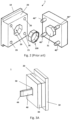
- Figs. 3-5 shows a mould box 1 according to an embodiment of the invention.
- the mould box 1 comprises a base plate 10 and a first mould plate 20 connected thereto.
- the first mould plate 20 is fixed in position relative to the base plate 10.
- the base plate 10 is fixedly connectable to an injection moulding machine, e.g. as described in connection with the prior art injection moulding machine 200 shown in Fig. 1 .
- the first mould plate may comprise one or more mould cavities (not shown) formed as depressions in a first surface 22 of the first mould plate 20.
- An opposite side, second side 23 of the first mould plate 20 faces the base plate 10, see e.g. Fig. 5 .
- the first mould plate 20 may be formed integrally with the base plate 10, or it may - as shown in Figs. 3-5 - be formed as individual/separate parts and subsequently be joined/connected, such that the first mould plate 20 is fixed to the base plate 10 at least during the injection moulding process.
- the first mould plate 20 may be connected to the base plate using for example bolts.
- the not shown one or more mould cavities may - in also not shown - further embodiments be formed in one or more cassettes attachable on - or insertable in suitable recesses in - the first surface 22 of the first mould plate 20.
- first mould plate and or the base plate may be equipped with sprue channels and runner channels necessary to connect the one or more mould cavities in the first mould plate 20 with an injection nozzle 225 of an injection moulding machine 200, such as an injection moulding machine as shown in Fig. 1 .
- the mould box 1 according to the invention - and as shown in Figs. 3-5 - further comprises a second mould plate 30.
- the second mould plate 30 is movably arranged relative to the first mould plate 20. Thereby, the second mould plate 30 is also movably arranged relative to the base plate 10.
- the mould box 1 according to the invention - and as shown in Figs. 3-5 - further comprises a guide rail system 40' configured for guiding the second mould plate linearly away from and towards the first mould plate 20.
- the guide rail system 40' allows the second mould plate 30 to be movably arranged relative to the base plate 10.
- the first mould plate 20 may also be movably arranged, relative to the base plate 10, the injection moulding machine 200 further comprising means for moving the first base plate 20 on the guide rail system 40'.
- the mould box 1 may comprise a third plate (not shown) arranged between the first and second mould plates 20, 30, where for example runner channels are arranged in third plate.
- a third plate may be fixed relative to the base plate 10 or it may be moveable on the guide rail system 40' in order to facilitate de shaping of the runner channels.
- the guide rail system 40' comprises a single guide rail pillar 40, only.
- the guide rail system may 40' may comprise more than a single guide rail pillar, but only one is needed.
- the guide rail pillar 40 is elongate, having a first end 43 and second end 44, an elongate body part 41 extending between the first end 43 and the second end 44, and a longitudinal axis A.
- the guide rail pillar 40 has a cross sectional shape perpendicular to the longitudinal axis A.
- the cross-section/cross-sectional shape forms a polygon.
- polygon or polygonal shape we mean any 2-dimensional shape formed with straight lines.
- Triangles, quadrilaterals, pentagons, and hexagons are all examples of polygons.
- a regular polygon has equal length sides with equal angles between each side. Any other polygon is an irregular polygon, which by definition has unequal length sides and unequal angles between sides.
- the cross-section of the guide pillar according to the invention may have any polygonal shape.
- the polygonal shape may in some embodiments be rectangular.
- a longer side length of the rectangular cross section/cross-sectional shape may be arranged vertically.
- the rectangular shape of the guide rail pillar 40 is oriented such that a longer side of the rectangular shape extends vertically and a shorter side of the rectangular shape extends horizontally.
- the guide rail pillar 40 having a cross-section/cross-sectional shape forming a polygon will result in the guide rail pillar 40 having a set of planar guide surfaces 45', 45", 46', 46" for cooperating with a bearing element 51 arranged on the second mould plate 30.
- the number of planar guide surfaces on the guide rail pillar 40 will depend on the number of sides of the polygonal cross-section/cross-sectional shape of the guide rail pillar 40.
- the guide rail pillar 40 shown in Figs. 3-5 having a rectangular cross section has two wider planar guide surfaces 45', 45" and two narrower planar guide surfaces 46', 46".
- the two wider planar guide surfaces 45',45" are parallel to each other and formed on opposed sides of the guide rail pillar 40.
- the two narrower planar guide surfaces 46', 46" are parallel to each other and formed on opposed sides of the guide rail pillar 40, but perpendicular to the two wider planar guide surfaces 45', 45".
- the second mould plate may comprise one or more mould cores (not shown) extending outward from a first surface 32 of the second mould plate 20, facing the first surface of the first mould plate 20.
- An opposite side, second surface 33 of the second mould plate320 faces away from the first mould plate 20 and the base plate 10, see e.g. Fig. 5 .
- the second mould plate 30 is arranged moveably relative to the first mould plate 20, such that the mould box may be completely closed (clamped together) to allow injection of the melted plastic, and such that the mould box 1 may be opened to extracted a moulded object, e.g. similar to the moulded object 100 shown in Fig. 2 .
- the not shown one or more mould cores may - in also not shown - further embodiments be formed in one or more cassettes attachable on - or insertable in suitable recesses in - the first surface 32 of the second mould plate 30.
- the mould box 1 according to the invention may form part of a clamping unit 270 of an injection moulding machine 200, in this case however with a single polygonal cross-section guide rail pillar 40 (instead of the four cylindrical guide rails 40", shown in Fig. 1 ) for guiding the movement of the second mould plate 30.
- the movement of the second mould plate 30 is performed by a linear drive mechanism 280, for example a hydraulic mechanism.
- the guide rail pillar 40 extends through a second opening 130 in the second mould plate 30.
- the first opening 130 in the second mould plate 30 is a through-going opening extending all the way through the second mould plate 30.
- the second opening 130 in the second mould plate 30 preferably has a cross sectional shape corresponding to the cross-sectional shape of the guide pillar 40 such that the guide pillar 40 may be slidably arranged therein.
- the second opening 130 in second mould plate 30 is provided with a bearing 50, such as a slide bearing.
- the second opening 130 in the second mould plate 30 is configured to receive the bearing 50.
- the bearing 50 comprises a bearing element 51 with inner surfaces configured for contacting the planar surfaces of the guide rail pillar 40.
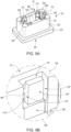
- the bearing element 51 may as shown in e.g. Fig. 5 have a main body part 52 and flange 53 having a larger cross sectional extent than that of the main body part 51, see e.g. Fig.5 .
- the second opening 130 in the second mould plate 30 may comprise one first section 131 configured for receiving the main body part 52 of the bearing element 51, and another, second section 132 with a larger cross-sectional extend than the first section 131, and configured for receiving the flange 53 of the bearing element 51, see e.g. Fig. 4C .
- the guide rail pillar 40 extends through a third opening 150 formed in the bearing 50.
- the third opening 150 in the bearing element 51 is a through-going opening extending all the way through the bearing element 51.
- the third opening 150 in the bearing element 51 preferably has a cross sectional shape corresponding to the cross-sectional shape of the guide pillar 40 such that the guide pillar 40 may be slidably arranged therein.
- the guide rail pillar 40 also may extend through a first opening 120 in the first mould plate 20.
- the first opening 120 in the first mould plate 20 is a through-going opening extending all the way through the first mould plate 20.
- the first opening 120 in the first mould plate 20 preferably has a cross sectional shape corresponding to the cross-sectional shape of the guide pillar 40 such that the guide pillar 40 may be received and fixedly anchored.
- the guide rail pillar 40 may have a main body part 41 and flange or protrusion 42 having a larger cross sectional extent than that of the main body part 41, see e.g. Fig.5 .
- the first opening 120 in the first mould plate 20 may comprise one first section 121 configured for receiving the main body part 41 of the guide rail pillar 40, and another, second section 122 with a larger cross-sectional extend than the first section 121, and configured for receiving the flange 42 of the guide rail pillar 40, see e.g. Fig. 4C .
- the guide rail pillar 40 at a first end 43 thereof may thereby be provided with a protrusion 41 configured for cooperating with an enlargement 121 of the second opening 120 in the first mould plate 20.
- the guide rail pillar 40 is anchored in first opening 120 through the first mould plate 20.
- the second opening 130 in the second mould plate 30 is formed centrally in the second mould plate 30.
- the first opening 130 in the first mould plate 30 is also formed centrally in the second mould plate 30.
- the one or more mould cavities may be formed around the first opening 130 in the first mould plate 20. Further, mating mould cores may be formed around the second opening in the movable, second mould plate 30.
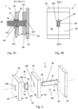
- Figs. 3A-C in various views, show a mould box 1 according to one embodiment of the invention in a first position, where the first and second mould plates 20, 30 are in close contact and clamped together. This illustrates a position, where plastic may be injected into the (not shown) mould cavity formed between the first and second mould plates 20, 30.
- figs. 4A-C show the mould box of Figs. 3A-C in a second position, where the first and second mould plates 20, 30 are separated from each other. This illustrates a position, where moulded objects may be removed from the mould cavity.
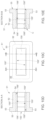
- Figs.6A-C in a sectional view, shows a guide rail pillar 40 and a second mould plate 30 slidably arranged thereon.
- the guide rail pillar 40 is of the type described above, having a polygonal cross section (perpendicular to the elongate axis of the guide rail pillar 40), such as a square or rectangular cross section.
- the guide rail pillar 40 has two parallelly arranged planar guide surfaces 45', 45".
- a bearing 50 is formed between the second mould plate 30 and the guide rail pillar 40.
- the bearing comprises a bearing element 51 arranged in a second opening 130 through the second mould plate 30 as described above.
- the bearing element 51 may be fixedly mounted in the second opening 130.
- the bearing element 51 has a through-going opening, third opening 150, formed there through.
- the third opening 150 is shaped and sized to mate at least with the has two parallelly arranged planar guide surfaces 45', 45" of the guide rail pillar 40, and configured to allow the second mould plate 30 with the bearing element 51 to slide reciprocally and linearly on the guide rail pillar 40 in a direction parallel to the longitudinal direction of the guide rail pillar 40.
- the third opening 150 for this purpose has two parallel internal bearing surfaces 155'. 155". As shown in Figs. 6A-C , the parallel internal bearing surfaces 155'. 155" in this case are formed across the entire width of the bearing element 51 and the second mould plate 30. Theoretically, his would be beneficial to take up any torsional forces on the second mould plate during the moulding process.
- Fig. 6A shows a situation where there are no torsional forces on the second mould plate 30 or the guide rail pillar 40.
- Fig. 6B shows a situation where there are no torsional forces on the second mould plate 30 or the guide rail pillar 40.
- Fig. 6B shows a situation where there are no torsional forces on the second mould plate 30 or the guide rail pillar 40.
- Fig. 6B shows a situation where there are no torsional forces on the second mould plate 30 or the guide rail pillar 40.
- Fig. 6B shows a situation where there are no torsional forces on the second mould plate 30 or the guide rail pillar 40.
- Fig. 6B shows a situation where there are no torsional forces on the second mould plate 30 or the guide rail pillar 40.
- Fig. 6B shows a situation where there are no torsional forces on the second mould plate 30 or the guide rail pillar 40.
- Fig. 6B shows a situation where there are no torsional forces on the second mould plate 30
- Line contact increases contact pressure between the guide rail pillar 40 and the bearing element 51, and can cause the bearing 50 to lock, resulting in abrasive wear on both bearing element 51 and guide rail pillar 51.
- the bearing thus experiences both static loads and dynamic friction, making it difficult to design for optimum performance in all load cases.
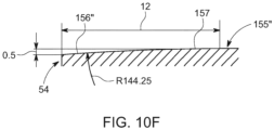
- Figs. 10A-F of which Figs. 10A-E are not to scale, this problem may be overcome by removing a portion of material from the internal bearing surfaces 155'. 155" to form a ledge or "rounding" 156', 156" of the internal bearing surfaces 155'. 155", at each end of the third opening 150, i.e. in the longitudinal direction, A.
- the bearing element 51 shown in Figs. 10A-F may substitute the bearing element 51 shown in Figs. 6A-C or Figs 3-5 .
- Such ledges 156', 156" will allow a slight rotation of the second mould plate 30 with the bearing element 51 relative to the corresponding parallel guide surfaces 45', 45" of the guide rail pillar 40 to accommodate for any asymmetrical loads on the second mould plate 30 to which the bearing element 51 is attached.
- FIG. 10F which is a detailed view of the ledge 156" of Fig. 10E , the removal of material is very minute. Thus, the ledge 156" only forms a very slight angle relative to the internal bearing surface 155".
- Figs. 7-9 show embodiments according to a first aspect of the invention, which will alleviate the problems of the prior art ( Figs. 6A-C ) and of the aspect of the invention shown in Figs. 10A-F .
- the bearing element 51 comprises - for at least one of the guide surfaces 45', 45" of the guide rail pillar 40 - a first planar bearing surface 64 and a second planar bearing surface 65 arranged in a common plane P 1 (see e.g. Figs. 7E , 8D or 9E ) and parallel to the corresponding planar guide surface 45', 45" of the guide rail pillar 40.
- the first planar bearing surface 64 and the second planar bearing surface 65 are spaced apart in the direction of the longitudinal axis A.
- the first bearing surface 64 is arranged at the first end 54 of the bearing element 51, and the second bearing surface 65 is arranged at the second end 55 of the bearing element 51.
- a cavity 74, 75; 74', 75'; 174, 175 is formed in the bearing element 51 at least partially below each of the first and second planar bearing surfaces 64, 65.
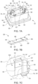
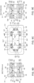
- FIG. 7A in a perspective view, shows a bearing element 50 according to the invention.
- the bearing element 51 comprises a main body part 52 with a first end 54 and a second end 55 and a through-going opening 150.
- the through-going opening 150 is configured for receiving the guide rail pillar 40.
- the through-going opening 150 extends from the first end 54 to the second end 55 of the main body part 52, and all the way through the main body part 52.
- the longitudinal axis A of the guide rail pillar 40 extends in the same direction as the direction from the first end 54 to the second end 55 of the main body part 52.
- the bearing element 51 is preferably arranged in an opening 130 through a mould plate, such as a second mould plate 30 of a mould box 1 of an injection moulding machine 200 as described above.
- the bearing element 51 may comprise a flange 53 with an increased extent (perpendicular to the longitudinal axis A) relative to the extent of the main body part 52 of bearing element 51 as also mentioned above.
- the bearing element 51 forms part of a bearing 50 between planar guide surfaces 45', 45" of a guide rail pillar 40 of a mould box 1, for example as shown in Figs. 6A- C , and a second mould plate 30 of the mould box 1, where the second mould plate 30 is moveably arranged on the guide rail 40.
- the through-going opening 150 in the embodiment shown in Figs. 7A-F has four inner surfaces 151', 151", 152', 152", see e.g. Fig 7D .
- the number of inner surface 151', 151", 152', 152" corresponds to the number of planar guide surface 45'.45" of the guide rail pillar 40.
- At least one inner surface 151', 151", 152', 152" comprises a first planar bearing surface 64 and a second planar bearing surface 65 arranged in a common plane P 1 , as shown in Fig. 7E , and parallel to the planar guide surface (45', 45").
- the first planar bearing surface 64 and the second planar bearing surface 65 are spaced apart in the direction of the longitudinal axis A.
- the first bearing surface 64 is arranged at the first end 54 and the second bearing surface 65 is arranged at the second end 55 of the bearing element 51.
- each of the two longer inner surfaces 151', 151" comprises two sets of such first and second planar bearing surfaces 64, 65, and each of the two shorter inner surfaces 152', 152" comprises a single set of such first and second planar bearing surfaces 64, 65.
- first and second planar bearing surfaces 64, 65 have a limited width, in a direction perpendicular to the elongate axis A.
- width of the first and second planar bearing surfaces 64, 65 may be varied.
- a single set of wider/broader first and second planar bearing surfaces 64, 65 may be used, for example extending the width of the inner surface 151', 151 ".
- the first and second bearing surfaces 64, 65 are elevated above the corresponding inner surface 151', 151", 152', 152" of the through-going opening 150.
- the first and second bearing surfaces 64, 65 are separated by an intermediary surface portion 66 being retracted from the common plane P 1 of the two bearing surfaces 64, 65.
- a cavity 74, 75; 74', 75'; 174, 175 is formed in the bearing element 51, below each of the first and second bearing surfaces 64, 65, such that a portion 84, 85 of the bearing element 51 is provided with a resilience relative to the main body part 52 of the bearing element 51.
- the cavity 74, 74', 174 below the first bearing surface 64 allows the portion 84 (on which the first bearing surface 64 is formed) to flex (at least slightly) relative to the main body part 52 proper, thereby providing the mentioned resilience.
- the cavity 75, 75', 175 below the second bearing surface 65 allows the portion 85 (on which the second bearing surface 65 is formed) to flex relative to the main body part 52 proper, thereby providing the mentioned resilience.
- the cavity 74; 74'; 174 below the first bearing surface 64 may be formed as a primary cavity 74; 74' extending into the main body part 52 of the bearing element 51 from an end surface at the first end 54 of the bearing element 51.
- the cavity 75; 75'; 175 below the second bearing surface 65 may be formed as a primary cavity 75; 75' extending into the main body part 52 of the bearing element 51 from an end surface at the second end 55 of the bearing element 51.
- the cavity, or primary cavity 74, 75 below each of the first and second bearing surfaces 64, 65 is formed as a ledge 74', 75'.
- the ledges 74', 75' may be formed with surfaces angled relative to the inner surface 151', 151", 152', 152".
- the first and the second bearing surfaces 64, 65 and the intermediary surface portion 66 are formed on a detachable plate member 56.
- a detachable plate member 56 One embodiment of the detachable plate member 56 as such is shown in Fig. 7B .
- the detachable plate member 56 is arranged in an elongate depression 57 formed in the inner surface 151', 151", 152', 152" of the through-going opening 150 through the bearing element 51.
- the elongate depressions 57 extends from said first end 54 to said second end 55 of the bearing element 51.
- the detachable plate member(s) 56 is/are configured such that it/they extend(s) from said first end 54 to said second end 55 of the bearing element 51 and fill out the entire length of the elongate depression(s) 57.
- the portions 84, 85 of the bearing element 51 form part of the detachable plate member 56. It will also be appreciated that the portions 84, 85 of the detachable plate member 56 are provided with a resilience relative to the main body part 52 by being able to flex slightly due at least to the cavities 74, 75 formed as the ledges 74', 75' in the bearing element 51.
- a reverse side of the detachable plate member 56 (reverse relative to the first and the second bearing surfaces 64, 65) may be formed with a single planar surface (not shown).
- the detachable plate member 56 on the reverse side (relative to the first and the second bearing surfaces 64, 65) comprises
- the intermediary surface portion 66 between the first and the second bearing surfaces 64, 65 on one side, and the intermediary surface portion 66' formed between the first and second abutment surfaces 64',65' on the reverse side the detachable plate member 56, will - in combination allow for a reduced material thickness between the first and the second bearing surfaces 64, 65 which will increase the resilience of the portions 84, 85 of the detachable plate member 56 such that uneven load distribution on the second mould plate 30 will not cause an edge of the bearing element 51 to come into direct contact with the planar surfaces 45.' 45" of the guide rail pillar 40.
- the elongate depression 57 formed in at least one of the inner surfaces 151', 151", 152', 152" of the through-going opening 150 through the bearing element 51 may in some (not shown) embodiments be formed with a planar bottom surface extending the entire length of the elongate depression.
- the elongate depression 57 formed in at least one of the inner surfaces 151', 151", 152', 152" of the through-going opening 150 through the bearing element 51 in a preferred embodiment, comprises
- the retracted surface portion 66' forms a void or space between the even bottomed surface and the detachable plate member 56, thereby increasing the flexibility of the bearing 50.
- the elongate depression 57 formed in the inner surface 151', 151", 152', 152" is formed with the first and second abutment plateaus 164, 165 separated by the intermediary depression 166, and the reverse side of the detachable plate member 56, relative to the first and the second bearing surfaces 64, 65, is formed with a single planar surface, a similar void or space is formed between the single planar surface of the detachable plate member 56 and the intermediary depression 166 between the abutment plateaus 164, 165, whereby a similar increased flexibility of the bearing 50 may achieved.
- the elongate depression 57 formed in the inner surface 151', 151", 152', 152" is formed with the first and second abutment plateaus 164, 165 separated by the intermediary depression 166
- the reverse side of the detachable plate member 56, relative to the first and the second bearing surfaces 64, 65 is formed with retracted surface portion 66' between the first and second abutment surfaces 64', 65', the abutment surfaces 64', 65' and the abutment plateaus 164, 165 are configured for abutting on each other.
- locking means may keep the detachable plate member 56 locked in the correct position in the elongate depression 57.
- Figs. 8A-E shows another embodiment of the bearing 50, in which the first and second bearing surfaces 64, 65 are not formed on a detachable plate member 56 arranged in an elongate depression 57 as shown in Figs. 7A-F .
- the first and second bearing surfaces 64, 65 are formed on portions 84, 85 formed in the sidewalls, inner surfaces 151', 151", 152', 152", of the bearing element 51.
- the portions 84, 85 may be formed as (separate) attachable and/or detachable parts relative to the main body part 52 of the bearing element 51.
- the portions 84, 85 with the respective the first and second bearing surfaces 64, 65 formed thereon are integrated with the main body part 52 of the bearing element 51.
- the main body part 52 of the bearing element 51 may be formed in one piece and the portions 84, 85 may be shaped by milling the cavity 74, 75 in the main body part 52.
- the main body part 52 of the bearing element 51 may be formed in one piece including the cavity 74, 75 defining the portions 84, 85 in an additive manufacturing process.
- the cavity 74 forms a bridge 84' between the main body part 52 as such and the portion 84 on which the first bearing surface 64 is formed.
- This bridge 84' thereby has a diminished material thickness, which will provide a desired resilience.
- the cavity 75 forms a bridge 85' between the main body part 52 as such and the portion 85 on which the second bearing surface 65 is formed.
- the cavity 74; below the first bearing surface 64 is formed as a primary cavity 74; extending into the main body part 52 of the bearing element 51 from an end surface at the first end 54 of the bearing element 51.
- the cavity 75; below the second bearing surface 65 is formed as a primary cavity 75; 75' extending into the main body part 52 of the bearing element 51 from an end surface at the second end 55 of the bearing element 51.
- the cavities 74, 75 extend in the same direction as the longitudinal axis A.
- the length (in the direction as the longitudinal axis A) of each of the cavities 74, 75 is preferably such that the cavity 74, 75 stretches under half of the first or second bearing surface 64, 65.
- the first and second bearing surfaces 64, 65 are separated by an intermediary surface portion 66 being retracted from the common plane P 1 of the two bearing surfaces 64, 65.
- the intermediary surface portion 66 may form part of one of the inner surfaces 151', 151", 152', 152".
- the first planar bearing surface 64 and the second planar bearing surface 65 are spaced apart in the direction of the longitudinal axis A.
- the first bearing surface 64 is arranged at the first end 54 and the second bearing surface 65 is arranged at the second end 55 of the bearing element 51.
- each of the two longer inner surfaces 151', 151" comprises two sets of such first and second planar bearing surfaces 64, 65
- each of the two shorter inner surfaces 152', 152" comprises a single set of such first and second planar bearing surfaces 64, 65.
- first and second planar bearing surfaces 64, 65 have a limited width, in a direction perpendicular to the elongate axis A.
- first and second planar bearing surfaces 64, 65 may be varied.
- a single set of wider/broader first and second planar bearing surfaces 64, 65 may be used, for example extending the width of the inner surface 151', 151".
- the first and second bearing surfaces 64, 65 are elevated above the corresponding inner surface 151', 151", 152', 152" of the through-going opening 150.
- FIGs. 9A-E generally corresponds to the embodiments described in connection with Figs. 8A-E above. However, in the Figs. 8A-E embodiment, there is provided an additional secondary cavity 174 below the first bearing surface 64 and additional secondary cavity 175 below the second bearing surface 65.
- the additional secondary cavity 174 below the first bearing surface 64 extends into the main body part 52 of the bearing element 51 from the inner surface 151', 151", 152', 152" of the through-going opening 150 from a position adjacent to the first bearing surface 64.
- the additional secondary cavity 175 below the second bearing surface 65 extends into the main body part 52 of the bearing element 51 from the inner surface 151', 151", 152', 152" of the through-going opening 150 from a position adjacent to the second bearing surface 65.
- the secondary cavity 174 adjacent to the first bearing surface 64 and the secondary cavity 175 adjacent to the second bearing surface 64 each comprise one first cavity portion 176 extending in a direction perpendicular to a plane of the inner surface 151', 151", 152', 152" of the through-going opening 150, and one second cavity portion 177 extending from the first cavity portion 176 in a direction parallel to the inner surface 151', 151", 152', 152" of the through-going opening 150.
- the portions 84, 85 of the bearing element 51 provided with a resilience relative to the main body part 52 by the cavities 74, 75 formed in the bearing element 51 are formed integral with the main body part 52 of the bearing element 51.
- FIGs. 9A-E embodiment shows that there is both a primary cavity 74 and a secondary cavity 174 under/below the first bearing surface 74, and both a primary cavity 75 and a secondary cavity 175 under/below the second bearing, in (not shown) embodiment it will - in principle - be possible to have only cavities of the secondary type extending under first and second bearing surfaces 64, 65.
- the main body part 52 of the bearing element 51 may be formed in one piece and the portions 84, 85 may be shaped by milling the secondary cavity 174, 175.
- the main body part 52 of the bearing element 51 may be formed in one piece including the secondary cavities 174, 175 defining the portions 84, 85 in an additive manufacturing process.
- two separations 70', 70" are provided in the bearing element 51 adjacent to each of the first and the second bearing surface 64, 65.
- the separations 70', 70" extend along a direction parallel to the longitudinal axis A, and in an entire length of the bearing surface 64, 65, and the separations extends from the inner surface 151', 151", 152', 152" of the through-going opening 150 into the main body part 52.
- the embodiments shown in Figs. 7A-F also comprises such separations 70', 70", but they are in the shape of the elongate depression 57.
- the portions 84, 85 may be shaped by milling the separations 70', 70" in the main body part 52.
- the main body part 52 of the bearing element 51 may be formed in one piece including the separations 70', 70" in an additive manufacturing process.
- a bearing element 51 may be arranged in an opening 130 through the mould plate 30 of the mould box 1, for example as shown in Figs 4B and 5 .
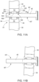
- Figs. 11A-B illustrates a bearing 50 according to another aspect of the invention.
- the bearing 50 comprises a bearing element 51.
- the bearing element 51 has a main body part 52 with a first end 54 and a second end 55.
- the bearing 50 also comprise two detachable bearing plates or portions 84, 85 for each planar surface 45' 45" of the guide rail pillar 40.
- the bearing plates or portions 84, 85 may be separate parts individually locked in position relative to the main body part 52 of the bearing element 51 (in the direction of the longitudinal axis A) by (not shown) locking means.
- the bearing plates or portions 84, 85 may also be connected to each other as one integrated part (not shown), for example as the detachable plate 56 described in connection with Figs.
- the bearing plates or portions 84, 85 may be locked in the correct position relative to the bearing element 51 (in the direction of the longitudinal axis A) by (not shown) locking means.
- the bearing plates or portions 84, 85 are connected to the bearing element 51 via semi-cylindrical surfaces 194, 195, one semi-cylindrical surface 194 at the first end 54, and another semi-cylindrical surface 195 at the second end 55.
Description
- The present invention relates to a bearing for linear guide rails for mold boxes for injection moulding processes.
- In injection moulding machines comprises an injection unit and a clamping unit for operating a mould box. In injection moulding machines, mould boxes typically comprises two mould half plates, or simply mould plates, arranged moveably relative to each other and guided by a set of guide rails. A clamping unit further comprises a actuator in the form of a linear drive mechanism for pressing at least one of the mould plates against one or more other mould plates, during injection of molten plastic performed by the injection unit. Typically, one mould plate is fixed relative to an injection moulding machine and the set of guide rails, and the other mould plate is slideable along the set of guide rails. Four cylindrical guide rails are commonly arranged in parallel and intersecting the four corners of the half plates. An actuator, the linear drive mechanism, drives the sliding of moveable half-plate/mould plate along the set of guide rails, between a position, where the half-plates closes to form a mould, and a position, where the half-plates are separated from each other, so that a moulded item may be removed from the mould box.
- The use of a set of four cylindrical guide rails, or main guide rail pillars, provides for making a very stable construction. It is however a disadvantage that such mould box constructions are very complicated and expensive to manufacture due to the high precision needed for making the half-plates/mould plates slide on the set of parallel guide rails, driving tight tolerance demands. Further, during use mould boxes are subject to uneven temperature distribution, causing uneven wear on the mould box parts. It is also a problem that the guide rails makes it difficult to design for auxiliary functions for example ejection pins, extraction arms etc.
- For this purpose it is suggested to provide a mould box where the half plates/mould plates are guided by a single linear guide rail, or at least a reduced number of guide rails. Below it is proposed to provide a mould box with one (or more) guide rails, which has/have a cross sectional shape perpendicular to a longitudinal axis of the guide rail(s), wherein the cross-section forms a polygon, such as a rectangular cross section. Such a guide rail will have at least two, three or more planar surfaces extending in the longitudinal direction of the guide rail, which planar surfaces needs to be supported by a bearing on any part - such as a half plate - movably arranged on the guide rail. Bearings for cylindrical guide rails are well known.
DE 298 02 231 U1 discloses a device for injection molding with at least two guide rods for two plates, the plates having bores through which a guide rod extends, wherein at least one bore has two inner surfaces arranged parallel to one another, and where each guide rod has mating outer surfaces arranged parallel to one another.EP 2 607 044 A2 discloses an injection molding tool comprising a molding insert with molding insert halves, and having cross-sectionally rectangular guiding profiles protruding forward in the direction of the first, nozzle-side tool half.US 4 718 845 discloses a stack mold comprising a center mold part, first and second outside mold parts moveable at both sides of the center mold part, and a rack and pinion gear arrangement to move the outside mold parts as well as a guide rod. - However, providing a bearing for a planar surface presents some unexpected trouble. A bearing needs to have a certain contact area. However, contact between planar surfaces of a guide rail as proposed and entirely planar bearing surface of a bearing element will result in problems at the edges, where the contact surface ends. When the guide rail and/or the half plate (mould plate) moving on the guide rail is subjected to uneven load distribution causing torsional forces, such an edge will cause increased wear on the guide rail/and or the bearing. In theory, such an effect may be alleviated by "rounding" the edge, or at least making a ledge in an angle to the bearing surface.
- However, if the stability of the contact in the bearing is to be maintained, it is necessary to provide such a rounding with a very small angle. It is expected that - over the width of a typical half plate - it is not possible to make such a low angle rounding. This could in theory be alleviated by increasing the length of the bearing, e.g., by increasing the thickness off the half plates/mould plates. However, this would be undesirably at least for space saving reasons.
- Another problem, which would not be solved even with an increased length of the bearing, is that - in practice - it is generally very difficult to make a small angle "rounding" without introducing a (microscopic) edge between the planar surface and the rounded surface of the bearing. Even such a very small edge may break the oil film on thee bearing surfaces and increase wear or cause the bearing surfaces to lock.
- Therefore, there is a need for an alternative bearing for polygonal cross section guide rails for mould boxes.
- It is therefore an object of the invention to solve the disadvantages of the prior art systems, and to increase the variety of options.
- The objects of the invention are - in a first aspect of the invention obtained by a bearing between planar guide surfaces of a guide rail pillar of a mould box and a mould plate of the mould box, the mould plate being moveably arranged on the guide rail, the guide rail having a longitudinal axis, the bearing comprising a bearing element,
- wherein the bearing element has a main body part with a first end and a second end and a through-going opening for receiving said guide rail pillar, the through-going opening extending from said first end to said second end through said body part, and the through-going opening having one inner surface for each planar guide surface of the guide rail pillar,
- wherein, for at least one of the guide surfaces of the guide rail pillar, the bearing element comprises a first planar bearing surface and a second planar bearing surface arranged in a common plane and parallel to the planar guide surface, and spaced apart in the direction of the longitudinal axis, the first bearing surface arranged at the first end and the second bearing surface arranged at the second end of the bearing element,
- wherein the first and second bearing surfaces are elevated above the corresponding inner surface of the through-going opening,
- wherein the first and second bearing surfaces are separated by an intermediary surface portion being retracted from the common plane of the two bearing surfaces, and
- wherein, below each of the first and second bearing surfaces, a cavity is formed in the bearing element, such that a portion of the bearing element is provided with a resilience relative to the main body part of the bearing element.
- Preferably, the bearing element comprises two planar bearing surfaces arranged as described above for each inner surface of the through-going opening.
- The cavity below (under) the first bearing surface allows the portion (on which the first bearing surface is formed) to flex relative to the main body part proper, thereby providing the mentioned resilience. Similarly, the cavity below the second bearing surface allows the portion (on which the second bearing surface is formed) to flex relative to the main body part proper, thereby providing the mentioned resilience.
- In an embodiment the cavity below the first bearing surface comprises a primary cavity extending into the main body part of the bearing element from an end surface at the first end, and wherein the cavity below the second bearing surface comprises a primary cavity extending into the main body part of the bearing element from an end surface at the second end.
- In a further embodiment the cavity below each of the first and second bearing surfaces is formed as a ledge.
- The ledges' may be formed with surfaces angled relative to the inner surface.
- In a further embodiment the first and the second bearing surfaces and the intermediary surface portion are formed on a detachable plate member,
wherein the detachable plate member is arranged in an elongate depression formed in the inner surface of the through-going opening through the bearing element, which elongate depression extends from said first end to said second end of the bearing element. - In this embodiment, the portions of the bearing element provided with a resilience relative to the main body part by the cavities formed in the bearing element form part of the detachable plate member.
- The reverse side of the detachable plate member, relative to the first and the second bearing surfaces may be formed with a single planar surface. In other embodiments however, the detachable plate member, on a reverse side relative to the first and the second bearing surfaces comprises
- a first abutment surface;
- a second abutment surface; and
- an intermediary surface portion being retracted from a common plane of the two abutment surfaces.
- In a further embodiment, the elongate depression formed in the inner surface of the through-going opening through the bearing element comprises
- a first abutment plateau at the second first end of the bearing element;
- a second abutment plateau at the second end of the bearing element, and
- an intermediary depression formed between the first and second abutment plateaus.
- Thus, in embodiments where the elongate depression formed in the inner surface is formed with an even bottomed surface, the retracted surface portion forms a void or space between the even bottomed surface and the detachable plate member, thereby increasing the flexibility of the bearing.
- In embodiments, where the elongate depression formed in the inner surface is formed with the first and second abutment plateaus separated by the intermediary depression, and the reverse side of the detachable plate member, relative to the first and the second bearing surfaces is formed with a single planar surface, a similar void or space is formed between the single planar surface of the detachable plate member and the intermediary depression between the abutment plateaus whereby a similar increased flexibility of the bearing may achieved.
- In embodiments, where the elongate depression formed in the inner surface is formed with the first and second abutment plateaus separated by the intermediary depression, and where the reverse side of the detachable plate member, relative to the first and the second bearing surfaces, is formed with retracted surface portion between the first and second abutment surfaces, an increased size void or space is formed between the elongate depression and the detachable plate member, whereby an increased flexibility of the bearing may achieved.
- It is noted that in embodiments, where the elongate depression formed in the inner surface is formed with the first and second abutment plateaus separated by the intermediary depression, and where the reverse side of the detachable plate member, relative to the first and the second bearing surfaces, is formed with retracted surface portion between the first and second abutment surfaces, the abutment surfaces and the abutment plateaus re configured for abutting on each other.
- Not shown locking means may keep the detachable plate member locked in the correct position in the
elongate depression 57. - In a further embodiment, the cavity below the first bearing surface comprises a secondary cavity extending into the main body part of the bearing element from the inner surface of the through-going opening from a position adjacent to the first bearing surface; and
wherein the cavity below the second bearing surface comprises a secondary cavity extending into the main body part of the bearing element from the inner surface of the through-going opening from a position adjacent to the second bearing surface. - In an embodiment hereof the secondary cavity adjacent to the first bearing surface and the secondary cavity adjacent to the second bearing surface each comprise one first cavity portion extending in a direction perpendicular to a plane of the inner surface of the through-going opening and one second cavity portion extending from the first cavity portion in a direction parallel to the inner surface of the through-going opening.
- In a further embodiment, the portions of the bearing element provided with a resilience relative to the main body part by the cavities formed in the bearing element are formed integral with the main body part of the bearing element.
- For example the main body part of the bearing element may be formed in one piece and the cavity portions may be shaped by milling the cavity in the main body part. In other embodiments, the bearing element may be formed in one piece in an additive manufacturing process.
- In such embodiments, the cavity forms a bridge between the main body part as such and the portion on which the first bearing surface is formed. This bridge thereby has a diminished material thickness, which will provide a desired resilience. Similarly, the cavity forms a bridge between the main body part as such and the portion on which the second bearing surface is formed.
- In a further embodiment, wherein two separations are provided in the bearing element adjacent to each of the first and the second bearing surface, the separations extending along a direction parallel to the longitudinal axis, and in an entire length of the bearing surface, and the separations extending from the inner surface of the through-going opening into the main body part.
- In embodiments thereof, where the portions of the bearing element provided with a resilience relative to the main body part by the cavities formed in the bearing element are formed integral with the main body part of the bearing element the main body part of the bearing element may be formed in one piece and the portions may be shaped by milling the cavity and/or the separations in the main body part.
- In further embodiment, the guide rail pillar comprises two parallel planar guide surfaces and where the bearing element comprise two opposed parallel inner surfaces corresponding to the two parallel planar guide surfaces, and where each of the two opposed parallel inner surfaces comprises at least one set of first and second bearing surfaces.
- In further embodiment, the guide rail pillar comprises a first two parallel planar guide surfaces and a second two parallel planar guide surfaces perpendicular to the first two parallel planar guide surfaces, and where the bearing element comprise a first two opposed parallel inner surfaces corresponding to the first two parallel planar guide surfaces, and a second two opposed parallel inner surfaces corresponding to the second two parallel planar guide surfaces, and where each of the parallel inner surfaces comprises at least one set of first and second bearing surfaces.
- In a further embodiment, the bearing element is arranged in an opening through the moveable mould plate of the mould box.
- The objects of the invention may - in a second aspect - be obtained by a mould box for an injection moulding machine, the mould box comprising
- a first mould plate;
- a second mould plate movably arranged relative to the first mould plate; and
- a guide rail system configured for guiding the second mould plate linearly away from and towards the first mould plate,
- wherein the guide rail system comprises a guide rail pillar,
- wherein the guide rail pillar has a longitudinal axis and a cross sectional shape perpendicular the longitudinal axis, and wherein the cross-section forms a polygon,
- wherein the guide rail pillar comprises planar guide surfaces equivalent to the number of sides in the polygonal cross-sectional shape of the guide rail pillar; and
- wherein a bearing according to any one of the embodiments of the first aspect described above, is arranged between the planar guide surfaces of the guide rail pillar and the second mould plate.
- In an embodiment also the first mould plate may be moveably arranged on the guide rail pillar wherein a bearing according to any one of the embodiments of the first aspect described above, is arranged between the planar guide surfaces of the guide rail pillar and the first mould plate.
- In further embodiments, the guide rail system comprises a single guide rail pillar only.
- In a further embodiment, the single guide rail pillar extends through a second opening in the second mould plate and first opening in a first mould plate and further, the second opening in the second mould plate is formed centrally in the second mould plate and the first opening in the first mould plate is formed centrally in the first mould plate.
- In a third aspect of the invention the objects may be obtained by an injection moulding machine comprising a mould box according to the first aspect of the invention.
- More particularly, in the third aspect, the objects of the invention are achieved by an injection moulding machine comprising
- a mould box comprising a first mould plate and a moveable second mould plate;
- a linear drive mechanism for moving the second mould plate; and
- an injection unit,
- a base plate connected to the frame of the injection machine and to the first mould plate; and
- a guide rail system configured for guiding the second mould plate linearly away from and towards the first mould plate,
- wherein the second mould plate is movably arranged relative to the first mould plate, and driven by the linear drive mechanism,
- wherein the guide rail system comprises a guide rail pillar,
- wherein the guide rail pillar has a longitudinal axis and a cross section perpendicular the longitudinal axis, where the cross-section forms a polygon;
- wherein the guide rail pillar comprises planar guide surfaces equivalent to the number of sides in the polygonal cross-sectional shape of the guide rail pillar; and
- wherein a bearing according to any one of the embodiments of the first aspect described above is arranged between the planar guide surfaces of the guide rail pillar and the second mould plate.
- In an embodiment also the first mould plate may be moveably arranged on the guide rail pillar wherein a bearing according to any one of the embodiments of the first aspect described above, is arranged between the planar guide surfaces of the guide rail pillar and the first mould plate.
- In further embodiments, the guide rail system comprises a single guide rail pillar only.
- In a further embodiment, the single guide rail pillar extends through a second opening in the second mould plate and first opening in a first mould plate and further, the second opening in the second mould plate is formed centrally in the second mould plate and the first opening in the first mould plate is formed centrally in the first mould plate.
- Above, and in the following, when referring to a guide rail system, a guide rail or guide rail pillar, reference may be made to any guide system, positioning system or alignment system of a mould box, a clamping unit or an injection moulding machine. However, a preferred use of the bearing is with polygonal cross-shape main guide rail pillars, i.e. the main guide rail system of a mould box, a clamping unit or an injection moulding machine. Main guide rail pillars, having a first end and a second, where the first end of the main guide rail pillar is connected to a fixed base plate, where the base plate is connected to an immobile relative to a frame of the injection moulding machine or at least a frame of the clamping unit of the injection moulding machine. Further, the second end of the main guide pillar(s) is/are connected to a second end structure of a clamping unit, which second end structure may be a plate and is arranged at a second end of the clamping unit frame. Further the second end structure is connected to an immobile relative to a frame of the injection moulding machine or at least a frame of the clamping unit of the injection moulding machine.
- A main guide rail system and any main guide rail pillars, thereof, are separate from any alignment system, and different therefrom.
- It should be emphasized that the term "comprises/comprising/comprised of" when used in this specification is taken to specify the presence of stated features, integers, steps or components but does not preclude the presence or addition of one or more other features, integers, steps, components or groups thereof.
- In the following, the invention will be described in greater detail with reference to embodiments shown by the enclosed figures. It should be emphasized that the embodiments shown are used for example purposes only and should not be used to limit the scope of the invention.
-
Fig. 1 schematically shows an outline of a prior art injection moulding machine; -
Fig. 2 , in a perspective view, shows components of a prior art mould box with two half-plates and a set of cylindrical guide rails; -
Fig.3A , in a perspective view, shows a mould box according to one embodiment of the invention in a first position; -
Fig. 3B , in a front view, shows the mould box ofFig. 3A in a sectional side view, shows the mould box ofFig. 3A ; -
Fig. 3C , in a sectional side view, shows the mould box ofFigs. 3A and3B ; -
Fig. 4A , in a perspective view, shows the mould box ofFigs. 3A-C in a second position; -
Fig. 4B , in a front view, shows the mould box ofFig. 4A ; -
Fig. 4C , in a sectional side view, shows the mould box ofFigs. 4A and4B ; -
Fig. 5 , in an exploded perspective view, shows the mould box ofFigs. 3A-C and4A-C ; and -
Fig. 6A , in a sectional view, shows a bearing between a guide rail with planar surfaces and a mould plate slidably arranged thereon, a bearing element arranged between the guide rail and the mould plate, in a situation where there are no torsional forces on the mould plate or the guide rail; -
Fig. 6B shows the bearing ofFig. 6A in a situation where the guide rail or the mould plate is subjected to torsional forces; -
Fig. 6C , show detail ofFig. 6B ; -
Fig. 7A , in a perspective view, shows a bearing element with separate bearing plate parts for a bearing according to a first embodiment of the invention; -
Fig. 7B , in a perspective view, shows a bearing plate part for the bearing element ofFig. 7A ; -
Fig. 7C , shows a detailed view of the bearing plate part arranged in the bearing element ofFig. 7A ; -
Fig. 7D , in a rear view, shows the bearing element ofFig. 7A ; -
Fig. 7E shows a section A-A though the bearing element ofFig. 7D ; -
Fig. 7F shows a section B-B though the bearing element ofFig. 7D ; -
Fig. 8A , in a perspective view, shows a bearing element with integrated bearing surface parts for a bearing according to a second embodiment of the invention; -
Fig. 8B , shows a detailed view of one integrated bearing surface part of the bearing element ofFig. 8A ; -
Fig. 8C in a rear view, shows the bearing element ofFig. 8A ; -
Fig. 8D shows a section A-A though the bearing element ofFig. 8C ; -
Fig. 8E shows a section B-B though the bearing element ofFig. 8C ; -
Fig. 9A , in a perspective view, shows a bearing element with alternatively shaped bearing surface parts for a bearing according to a third embodiment of the invention; -
Fig. 9B , shows a detailed view of one integrated bearing surface part of the bearing element ofFig. 9A ; -
Fig. 9C in a rear view, shows the bearing element ofFig. 9A ; -
Fig. 9D shows a section A-A though the bearing element ofFig. 9C ; -
Fig. 9E shows a section B-B though the bearing element ofFig. 9C ; -
Fig. 10A , in a perspective view, shows a bearing element with profiled bearing surfaces for a bearing according to another aspect of the invention; -
Fig. 10B shows a detailed view of one profiled bearing surface of the bearing element ofFig. 10A ; -
Fig. 10C , in a rear view, shows the bearing element ofFig. 10A ; -
Fig. 10D shows a section A-A though the bearing element ofFig. 10C ; -
Fig. 10E shows a section B-B though the bearing element ofFig. 10C ; -
Fig. 10F , in a side sectional view, shows a detail of a profile of a bearing surface ofFigs.10E ; -
Fig. 11A , in a sectional view, shows a bearing between a guide rail with planar surfaces and a mould plate slidably arranged thereon, a bearing element according to yet another aspect of the invention arranged between the guide rail and the mould plate, in a situation where there are no torsional forces on the mould plate or the guide rail; and -
Fig. 11B shows the bearing ofFig. 11A in a situation where the guide rail or the mould plate is subjected to torsional forces. -
Fig. 1 illustrates schematically aninjection moulding machine 200 as known in the art. Theinjection moulding machine 200 generally comprises aninjection unit 210, shown in the left side of the figure, and aclamping unit 270, shown in the right side of the figure. Theinjection unit 210 handles injection of plastic material into a mould formed in theclamping unit 270 of theinjection moulding machine 200. Theinjection unit 210 and theclamping unit 270 of theinjection moulding machine 200 are attachable to a mount/frame 201. -
Injection moulding machines 200 generally works in the following way:Plastic granules 105 are fed into thebarrel 260 of areciprocating screw 220 of theinjection unit 210 via ahopper 240. Thereciprocating screw 220 is driven by adrive mechanism 230, such as an electrical motor. Theplastic granules 105 fed through thehopper 240 are then transported towards the clampingunit 270 by the reciprocal screw, while being compacted and they are heated by heating devices 250 surrounding thereciprocating screw 220, until they melt and reach a suitable viscosity at anozzle 225 at the entrance to theclamping unit 270 with the mould. The mould is formed in amould box 1. - The fluid plastic material is fed from the
nozzle 225 throughsprue channels 226 in abase plate 10 of themould box 1, and reaches amould cavity 21 formed in afirst mould plate 20 of themould box 1. Thefirst mould plate 20 of themould box 1 is connected to thebase plate 10. Thebase plate 10 is connected to the frame 201. Asecond mould plate 30 which may comprise a mould core and/or further portions of a mould cavity is arranged moveably relative to thefirst mould plate 20, such that the mould box may be completely closed (clamped together) to allow injection of the melted plastic, and such that themould box 1 may be opened to extracted a moulded object 100 (seeFig. 2 ). - In
Fig. 1 thesecond mould plate 30 is attached to amoveable platen 290. The moveable platen 290 - and thereby the second mould plate 30 - is slideably arranged on a set ofcylindrical guide rails 40". Typically, theclamping unit 270 ofinjection moulding machines 200 comprises four cylindrical guide rails 400 for guiding the movement of themoveable platen 290 with thesecond mould plate 30. The movement of themoveable platen 290 with thesecond mould plate 30 is performed by alinear drive mechanism 280, typically a hydraulic mechanism. - Each of the (main)
guide rail pillars 40" of the (main) guide rail system of themould box 1 of theclamping unit 270 has an elongate body, which is cylindrical, and has afirst end 443 and asecond end 444. Thefirst end 443 is fixed to thebase plate 10, which is fixed to a frame (not shown) of theclamping device 270. The frame of theclamping unit 270 may form part of the frame 201 of theinjection moulding machine 200, or may be fixed thereto. - The opposite end, the
second end 444, of the elongate body of each mainguide rail pillars 40" is fixedly connected to asecond end structure 15 of theclamping unit 270. Thesecond end structure 15 of theclamping unit 270 is fixed to the frame (not shown) of theclamping device 270, which, as mentioned in the previous paragraph, may form part of the frame 201 of theinjection moulding machine 200, or may be fixed thereto. - The
second end structure 15 may also, as shown inFig. 1 , form a mount for thelinear drive mechanism 280. - Now, returning to
moveable platen 290 with thesecond mould plate 30, thismoveable platen 290 comprises through-going slide bearings, or ball bearings, slidably receiving thecylindrical guide rails 40". - In an injection process, the
linear drive mechanism 280 clamps thefirst mould plate 20 and thesecond mould plate 30 together, whereupon plastic is injected from thereciprocal screw 220 through thenozzle 225 and into themould cavity 21. When the plastic has filled themould cavity 21 completely, and has cooled sufficiently for the plastic to be in solid state, then thelinear drive mechanism 280 moves thesecond mould plate 30 away from thefirst mould plate 20, and the moulded object is ejected from themould cavity 21 in thefirst mould plate 20. The ejection of the mouldedobject 100 is typically done by ejector pins (not shown) formed in/through thebase plate 10. -
Fig. 2 shows a priorart mould box 1 for an injection moulding machine 200 (as outlined inFig. 1 ), and amoulded object 100. Themould box 1 is shown in a separated state where the mouldedobject 100 is visible between two half plates, ormould plates mould box 1. Thus, the hemould box 1 comprises twomould plates first mould plate 20, here shown to comprise amould cavity 21 of a mould, is connected to abase plate 10 of themould box 1. Thefirst mould plate 20 and thebase plate 10 may form one integrated part, or they may be formed as separate parts and joined subsequently by suitable means, e.g. bolts. Amould cavity 21 is formed as a depression in a surface of thefirst mould plate 20. - The
first mould plate 20 is - via the base plate 10 -connected to aninjection moulding machine 200, e.g. as described above. Thebase plate 10 may thus be connected to a frame 201 as shown inFig. 1 . - A
second mould plate 30 is moveably arranged relative to thefirst mould plate 20 and theinjection moulding machine 200. Thesecond mould plate 30 is slideably arranged on a set ofguide rails 40" of a guide rail system configured for guiding thesecond mould plate 30 linearly away from and towards thefirst mould plate 20. - The set of
guide rails 40" comprises fourcylindrical guide rails 40". The guide rails 40" are arranged to slide over bearings (not shown) provided through thesecond mould plate 30. InFig. 2 only a portion of the guide rails 40" is seen. - The guide rails 40" are fixedly secured in the openings 24 provided in the
first mould plate 20. There is one opening 24 perguide rail 40". - In
Fig. 2 thecylindrical guide rails 40" extend through openings through thesecond mould plate 30 itself, as opposed to the version shown inFig. 1 , where thesecond mould plate 30 is connected to amoveable platen 290, which has bearings for theguide rails 40". - The
second mould plate 30 is shown with a core 31 configured for mating with themould cavity 21 in thefirst mould plate 20 to form a shape corresponding to the mouldedobject 100. -
Figs. 3-5 shows amould box 1 according to an embodiment of the invention. Themould box 1 comprises abase plate 10 and afirst mould plate 20 connected thereto. During use in injection moulding processes, thefirst mould plate 20 is fixed in position relative to thebase plate 10. Thebase plate 10 is fixedly connectable to an injection moulding machine, e.g. as described in connection with the prior artinjection moulding machine 200 shown inFig. 1 . The first mould plate may comprise one or more mould cavities (not shown) formed as depressions in afirst surface 22 of thefirst mould plate 20. An opposite side,second side 23 of thefirst mould plate 20 faces thebase plate 10, see e.g.Fig. 5 . - The
first mould plate 20 may be formed integrally with thebase plate 10, or it may - as shown inFigs. 3-5 - be formed as individual/separate parts and subsequently be joined/connected, such that thefirst mould plate 20 is fixed to thebase plate 10 at least during the injection moulding process. Thefirst mould plate 20 may be connected to the base plate using for example bolts. - The not shown one or more mould cavities may - in also not shown - further embodiments be formed in one or more cassettes attachable on - or insertable in suitable recesses in - the
first surface 22 of thefirst mould plate 20. - Further, the first mould plate and or the base plate may be equipped with sprue channels and runner channels necessary to connect the one or more mould cavities in the
first mould plate 20 with aninjection nozzle 225 of aninjection moulding machine 200, such as an injection moulding machine as shown inFig. 1 . - The
mould box 1 according to the invention - and as shown inFigs. 3-5 - further comprises asecond mould plate 30. - The
second mould plate 30 is movably arranged relative to thefirst mould plate 20. Thereby, thesecond mould plate 30 is also movably arranged relative to thebase plate 10. - The
mould box 1 according to the invention - and as shown inFigs. 3-5 - further comprises a guide rail system 40' configured for guiding the second mould plate linearly away from and towards thefirst mould plate 20. - The guide rail system 40' allows the
second mould plate 30 to be movably arranged relative to thebase plate 10. - In other not shown embodiments, the
first mould plate 20 may also be movably arranged, relative to thebase plate 10, theinjection moulding machine 200 further comprising means for moving thefirst base plate 20 on the guide rail system 40'. - In yet other - not shown - embodiments, the
mould box 1 may comprise a third plate (not shown) arranged between the first andsecond mould plates base plate 10 or it may be moveable on the guide rail system 40' in order to facilitate de shaping of the runner channels. - As shown in
Figs. 3-5 , the guide rail system 40' comprises a singleguide rail pillar 40, only. In principle, the guide rail system may 40' may comprise more than a single guide rail pillar, but only one is needed. - The
guide rail pillar 40 is elongate, having afirst end 43 andsecond end 44, anelongate body part 41 extending between thefirst end 43 and thesecond end 44, and a longitudinal axis A. Theguide rail pillar 40 has a cross sectional shape perpendicular to the longitudinal axis A. - The cross-section/cross-sectional shape forms a polygon.
- We note that by a polygon or polygonal shape we mean any 2-dimensional shape formed with straight lines. Triangles, quadrilaterals, pentagons, and hexagons are all examples of polygons.
- There are two main types of polygon - regular and irregular. A regular polygon has equal length sides with equal angles between each side. Any other polygon is an irregular polygon, which by definition has unequal length sides and unequal angles between sides. In principle, the cross-section of the guide pillar according to the invention may have any polygonal shape.
- However, as shown in
Figs. 3-5 , the polygonal shape may in some embodiments be rectangular. - In some embodiments a longer side length of the rectangular cross section/cross-sectional shape may be arranged vertically. Thus, the rectangular shape of the
guide rail pillar 40 is oriented such that a longer side of the rectangular shape extends vertically and a shorter side of the rectangular shape extends horizontally. - In any case, the
guide rail pillar 40 having a cross-section/cross-sectional shape forming a polygon will result in theguide rail pillar 40 having a set of planar guide surfaces 45', 45", 46', 46" for cooperating with a bearingelement 51 arranged on thesecond mould plate 30. The number of planar guide surfaces on theguide rail pillar 40 will depend on the number of sides of the polygonal cross-section/cross-sectional shape of theguide rail pillar 40. Theguide rail pillar 40 shown inFigs. 3-5 having a rectangular cross section has two wider planar guide surfaces 45', 45" and two narrower planar guide surfaces 46', 46".The two wider planar guide surfaces 45',45" are parallel to each other and formed on opposed sides of theguide rail pillar 40. Similarly, the two narrower planar guide surfaces 46', 46" are parallel to each other and formed on opposed sides of theguide rail pillar 40, but perpendicular to the two wider planar guide surfaces 45', 45". - The second mould plate may comprise one or more mould cores (not shown) extending outward from a
first surface 32 of thesecond mould plate 20, facing the first surface of thefirst mould plate 20. An opposite side,second surface 33 of the second mould plate320 faces away from thefirst mould plate 20 and thebase plate 10, see e.g.Fig. 5 . Thesecond mould plate 30 is arranged moveably relative to thefirst mould plate 20, such that the mould box may be completely closed (clamped together) to allow injection of the melted plastic, and such that themould box 1 may be opened to extracted a moulded object, e.g. similar to the mouldedobject 100 shown inFig. 2 . - As is the case with the
first mould plate 20, described above, the not shown one or more mould cores (and/or further portions of mould cavities) may - in also not shown - further embodiments be formed in one or more cassettes attachable on - or insertable in suitable recesses in - thefirst surface 32 of thesecond mould plate 30. - As is the case with the prior art examples described above, the
mould box 1 according to the invention may form part of aclamping unit 270 of aninjection moulding machine 200, in this case however with a single polygonal cross-section guide rail pillar 40 (instead of the fourcylindrical guide rails 40", shown inFig. 1 ) for guiding the movement of thesecond mould plate 30. The movement of thesecond mould plate 30 is performed by alinear drive mechanism 280, for example a hydraulic mechanism. - As shown in
Figs. 3-5 , theguide rail pillar 40 extends through asecond opening 130 in thesecond mould plate 30. Thefirst opening 130 in thesecond mould plate 30 is a through-going opening extending all the way through thesecond mould plate 30. - The
second opening 130 in thesecond mould plate 30 preferably has a cross sectional shape corresponding to the cross-sectional shape of theguide pillar 40 such that theguide pillar 40 may be slidably arranged therein. - Preferably, the
second opening 130 insecond mould plate 30 is provided with abearing 50, such as a slide bearing. In this case thesecond opening 130 in thesecond mould plate 30 is configured to receive thebearing 50. - The
bearing 50 comprises a bearingelement 51 with inner surfaces configured for contacting the planar surfaces of theguide rail pillar 40. The bearingelement 51 may as shown in e.g.Fig. 5 have amain body part 52 andflange 53 having a larger cross sectional extent than that of themain body part 51, see e.g.Fig.5 . In such cases thesecond opening 130 in thesecond mould plate 30 may comprise onefirst section 131 configured for receiving themain body part 52 of the bearingelement 51, and another,second section 132 with a larger cross-sectional extend than thefirst section 131, and configured for receiving theflange 53 of the bearingelement 51, see e.g.Fig. 4C . - As shown in
Figs. 3-5 , theguide rail pillar 40 extends through athird opening 150 formed in thebearing 50. Thethird opening 150 in thebearing element 51 is a through-going opening extending all the way through the bearingelement 51. Thethird opening 150 in thebearing element 51 preferably has a cross sectional shape corresponding to the cross-sectional shape of theguide pillar 40 such that theguide pillar 40 may be slidably arranged therein. - As shown in
Figs. 3-5 , theguide rail pillar 40 also may extend through afirst opening 120 in thefirst mould plate 20. Thefirst opening 120 in thefirst mould plate 20 is a through-going opening extending all the way through thefirst mould plate 20. Thefirst opening 120 in thefirst mould plate 20 preferably has a cross sectional shape corresponding to the cross-sectional shape of theguide pillar 40 such that theguide pillar 40 may be received and fixedly anchored. - The
guide rail pillar 40 may have amain body part 41 and flange orprotrusion 42 having a larger cross sectional extent than that of themain body part 41, see e.g.Fig.5 . In such cases, and as shown in e.g.Fig 4C , thefirst opening 120 in thefirst mould plate 20 may comprise onefirst section 121 configured for receiving themain body part 41 of theguide rail pillar 40, and another,second section 122 with a larger cross-sectional extend than thefirst section 121, and configured for receiving theflange 42 of theguide rail pillar 40, see e.g.Fig. 4C . Theguide rail pillar 40 at afirst end 43 thereof may thereby be provided with aprotrusion 41 configured for cooperating with anenlargement 121 of thesecond opening 120 in thefirst mould plate 20. - Thus, the
guide rail pillar 40 is anchored infirst opening 120 through thefirst mould plate 20. - In either case, and as shown in
Figs. 3-5 , thesecond opening 130 in thesecond mould plate 30 is formed centrally in thesecond mould plate 30. In this case, it follows that thefirst opening 130 in thefirst mould plate 30 is also formed centrally in thesecond mould plate 30. - The one or more mould cavities may be formed around the
first opening 130 in thefirst mould plate 20. Further, mating mould cores may be formed around the second opening in the movable,second mould plate 30. -
Figs. 3A-C , in various views, show amould box 1 according to one embodiment of the invention in a first position, where the first andsecond mould plates second mould plates figs. 4A-C show the mould box ofFigs. 3A-C in a second position, where the first andsecond mould plates -
Figs.6A-C , in a sectional view, shows aguide rail pillar 40 and asecond mould plate 30 slidably arranged thereon. Theguide rail pillar 40 is of the type described above, having a polygonal cross section (perpendicular to the elongate axis of the guide rail pillar 40), such as a square or rectangular cross section. Thus, as shown inFigs. 6A-C , theguide rail pillar 40 has two parallelly arranged planar guide surfaces 45', 45". - A
bearing 50 is formed between thesecond mould plate 30 and theguide rail pillar 40. The bearing comprises a bearingelement 51 arranged in asecond opening 130 through thesecond mould plate 30 as described above. The bearingelement 51 may be fixedly mounted in thesecond opening 130. - The bearing
element 51 has a through-going opening,third opening 150, formed there through. Thethird opening 150 is shaped and sized to mate at least with the has two parallelly arranged planar guide surfaces 45', 45" of theguide rail pillar 40, and configured to allow thesecond mould plate 30 with the bearingelement 51 to slide reciprocally and linearly on theguide rail pillar 40 in a direction parallel to the longitudinal direction of theguide rail pillar 40. - The
third opening 150 for this purpose has two parallelinternal bearing surfaces 155'. 155". As shown inFigs. 6A-C , the parallelinternal bearing surfaces 155'. 155" in this case are formed across the entire width of the bearingelement 51 and thesecond mould plate 30. Theoretically, his would be beneficial to take up any torsional forces on the second mould plate during the moulding process. -
Fig. 6A shows a situation where there are no torsional forces on thesecond mould plate 30 or theguide rail pillar 40. However, especially if theremould box 1 guide rail system 40' has only a singleguide rail pillar 40, there is a risk that an uneven pressure influences thesecond mould plate 30 relative to theguide rail pillar 40 such that thesecond mould plate 30 is forced to rotate slightly relative to theguide rail pillar 40. Such a situation is shown inFig. 6B . The encircled area shown in dashed line inFig. 6B is blown up inFig. 6C . FromFig. 6C it is evident that torsion between the second mould plate and the guide rail pillar may result in two line contacts 155'", 155"". Line contact increases contact pressure between theguide rail pillar 40 and the bearingelement 51, and can cause thebearing 50 to lock, resulting in abrasive wear on both bearingelement 51 andguide rail pillar 51. The bearing thus experiences both static loads and dynamic friction, making it difficult to design for optimum performance in all load cases. - As illustrated in
Figs. 10A-F , of whichFigs. 10A-E are not to scale, this problem may be overcome by removing a portion of material from theinternal bearing surfaces 155'. 155" to form a ledge or "rounding" 156', 156" of theinternal bearing surfaces 155'. 155", at each end of thethird opening 150, i.e. in the longitudinal direction, A. The bearingelement 51 shown inFigs. 10A-F may substitute the bearingelement 51 shown inFigs. 6A-C orFigs 3-5 .Such ledges 156', 156" will allow a slight rotation of thesecond mould plate 30 with the bearingelement 51 relative to the corresponding parallel guide surfaces 45', 45" of theguide rail pillar 40 to accommodate for any asymmetrical loads on thesecond mould plate 30 to which thebearing element 51 is attached. - As can be appreciated from
Fig. 10F , which is a detailed view of theledge 156" ofFig. 10E , the removal of material is very minute. Thus, theledge 156" only forms a very slight angle relative to theinternal bearing surface 155". - In practice it has proven very hard to make
such ledges 156', 156"or "roundings" without introducing a (microscopic)edge 157 at the boundary between theplanar bearing surface 155', 155" and theledge 156', 156". Even this verysmall edge 157 is expected to break the oil film between the bearing surfaces and to increase wear on theguide rail pillar 40 or cause locking there between. -
Figs. 7-9 show embodiments according to a first aspect of the invention, which will alleviate the problems of the prior art (Figs. 6A-C ) and of the aspect of the invention shown inFigs. 10A-F . - According to this aspect of the invention, the bearing
element 51 comprises - for at least one of the guide surfaces 45', 45" of the guide rail pillar 40 - a firstplanar bearing surface 64 and a secondplanar bearing surface 65 arranged in a common plane P1 (see e.g.Figs. 7E ,8D or9E ) and parallel to the correspondingplanar guide surface guide rail pillar 40. The firstplanar bearing surface 64 and the secondplanar bearing surface 65 are spaced apart in the direction of the longitudinal axis A. Thefirst bearing surface 64 is arranged at thefirst end 54 of the bearingelement 51, and thesecond bearing surface 65 is arranged at thesecond end 55 of the bearingelement 51. In order to provide a resilience of the first and second bearing surfaces 64, 65 relative to amain body part 52 of the bearingelement 51, and thereby ensure that the first andsecond bearing surface planar guide surface guide rail pillar 40 to avoid any edges being the sole contact between theguide rail pillar 40 and the bearingelement 50, acavity bearing element 51 at least partially below each of the first and second planar bearing surfaces 64, 65. - Returning now to
Figs. 7A-E , these figures show a first embodiment of the invention.Fig. 7A , in a perspective view, shows abearing element 50 according to the invention. The bearingelement 51 comprises amain body part 52 with afirst end 54 and asecond end 55 and a through-goingopening 150. The through-goingopening 150 is configured for receiving theguide rail pillar 40. - The through-going
opening 150 extends from thefirst end 54 to thesecond end 55 of themain body part 52, and all the way through themain body part 52. - Thereby, the longitudinal axis A of the
guide rail pillar 40 extends in the same direction as the direction from thefirst end 54 to thesecond end 55 of themain body part 52. - The bearing
element 51 is preferably arranged in anopening 130 through a mould plate, such as asecond mould plate 30 of amould box 1 of aninjection moulding machine 200 as described above. For this purpose the bearingelement 51 may comprise aflange 53 with an increased extent (perpendicular to the longitudinal axis A) relative to the extent of themain body part 52 of bearingelement 51 as also mentioned above. - The bearing
element 51 forms part of abearing 50 between planar guide surfaces 45', 45" of aguide rail pillar 40 of amould box 1, for example as shown inFigs. 6A- C , and asecond mould plate 30 of themould box 1, where thesecond mould plate 30 is moveably arranged on theguide rail 40. - The through-going
opening 150 in the embodiment shown inFigs. 7A-F has fourinner surfaces 151', 151", 152', 152", see e.g.Fig 7D . - Preferably, the number of
inner surface 151', 151", 152', 152" corresponds to the number ofplanar guide surface 45'.45" of theguide rail pillar 40. - At least one
inner surface 151', 151", 152', 152" comprises a firstplanar bearing surface 64 and a secondplanar bearing surface 65 arranged in a common plane P1, as shown inFig. 7E , and parallel to the planar guide surface (45', 45"). The firstplanar bearing surface 64 and the secondplanar bearing surface 65 are spaced apart in the direction of the longitudinal axis A. Thefirst bearing surface 64 is arranged at thefirst end 54 and thesecond bearing surface 65 is arranged at thesecond end 55 of the bearingelement 51. - In the embodiment, shown in
Figs. 7A-F each of the two longerinner surfaces 151', 151" comprises two sets of such first and second planar bearing surfaces 64, 65, and each of the two shorterinner surfaces 152', 152" comprises a single set of such first and second planar bearing surfaces 64, 65. - In the shown embodiment the first and second planar bearing surfaces 64, 65 have a limited width, in a direction perpendicular to the elongate axis A. However, it will be appreciated that the width of the first and second planar bearing surfaces 64, 65 may be varied. Thus, instead of two set of first and second planar bearing surfaces 64, 65 on the two longer
inner surfaces 151', 151", a single set of wider/broader first and second planar bearing surfaces 64, 65 may be used, for example extending the width of theinner surface 151', 151 ". - As shown in e.g.
Fig. 7D , the first and second bearing surfaces 64, 65 are elevated above the correspondinginner surface 151', 151", 152', 152" of the through-goingopening 150. - As shown in e.g.
Figs. 7E and F , the first and second bearing surfaces 64, 65 are separated by anintermediary surface portion 66 being retracted from the common plane P1 of the two bearingsurfaces - As also mentioned above, a
cavity bearing element 51, below each of the first and second bearing surfaces 64, 65, such that aportion element 51 is provided with a resilience relative to themain body part 52 of the bearingelement 51. - The
cavity first bearing surface 64 allows the portion 84 (on which thefirst bearing surface 64 is formed) to flex (at least slightly) relative to themain body part 52 proper, thereby providing the mentioned resilience. Similarly, thecavity second bearing surface 65 allows the portion 85 (on which thesecond bearing surface 65 is formed) to flex relative to themain body part 52 proper, thereby providing the mentioned resilience. - Generally, the
cavity 74; 74'; 174 below thefirst bearing surface 64 may be formed as aprimary cavity 74; 74' extending into themain body part 52 of the bearingelement 51 from an end surface at thefirst end 54 of the bearingelement 51. And, generally, thecavity 75; 75'; 175 below thesecond bearing surface 65 may be formed as aprimary cavity 75; 75' extending into themain body part 52 of the bearingelement 51 from an end surface at thesecond end 55 of the bearingelement 51. - More specifically and as best illustrated in
Figs. 7E and 7F , the cavity, orprimary cavity - The ledges 74', 75' may be formed with surfaces angled relative to the
inner surface 151', 151", 152', 152". - As also shown in
Figs. 7E and 7F , the first and the second bearing surfaces 64, 65 and theintermediary surface portion 66 are formed on adetachable plate member 56. One embodiment of thedetachable plate member 56 as such is shown inFig. 7B . - The
detachable plate member 56 is arranged in anelongate depression 57 formed in theinner surface 151', 151", 152', 152" of the through-goingopening 150 through the bearingelement 51. - Preferably, and as shown in the
Figs 7A-F , theelongate depressions 57 extends from saidfirst end 54 to saidsecond end 55 of the bearingelement 51. - Preferably also the detachable plate member(s) 56 is/are configured such that it/they extend(s) from said
first end 54 to saidsecond end 55 of the bearingelement 51 and fill out the entire length of the elongate depression(s) 57. - It will be appreciated, that in this embodiment, the
portions element 51 form part of thedetachable plate member 56. It will also be appreciated that theportions detachable plate member 56 are provided with a resilience relative to themain body part 52 by being able to flex slightly due at least to thecavities bearing element 51. - It will be appreciated that a reverse side of the detachable plate member 56 (reverse relative to the first and the second bearing surfaces 64, 65) may be formed with a single planar surface (not shown).
- In other embodiments however, and as shown in e.g.
Fig 7B , thedetachable plate member 56, on the reverse side (relative to the first and the second bearing surfaces 64, 65) comprises - a first abutment surface 64';
- a
second abutment surface 65' formed in a common plane, P2, with the first abutment surface 64'; and - an intermediary surface portion 66' being retracted from the common plane P2 of the two
abutment surfaces 64', 65'. - The
intermediary surface portion 66 between the first and the second bearing surfaces 64, 65 on one side, and the intermediary surface portion 66' formed between the first and second abutment surfaces 64',65' on the reverse side thedetachable plate member 56, will - in combination allow for a reduced material thickness between the first and the second bearing surfaces 64, 65 which will increase the resilience of theportions detachable plate member 56 such that uneven load distribution on thesecond mould plate 30 will not cause an edge of the bearingelement 51 to come into direct contact with the planar surfaces 45.' 45" of theguide rail pillar 40. - The
elongate depression 57 formed in at least one of theinner surfaces 151', 151", 152', 152" of the through-goingopening 150 through the bearingelement 51 may in some (not shown) embodiments be formed with a planar bottom surface extending the entire length of the elongate depression. - However, as is evident from especially
Figs. 7E and 7F , theelongate depression 57 formed in at least one of theinner surfaces 151', 151", 152', 152" of the through-goingopening 150 through the bearingelement 51, in a preferred embodiment, comprises - a
first abutment plateau 164 at the secondfirst end 54 of the bearingelement 51; - a
second abutment plateau 165 at thesecond end 55 of the bearingelement 51, and - an
intermediary depression 166 formed between the first and second abutment plateaus 164, 165. - It will be appreciated that, in embodiments where the
elongate depression 57 formed in theinner surface 151', 151", 152', 152" is formed with an even bottomed surface (entirely planar bottom surface), the retracted surface portion 66' forms a void or space between the even bottomed surface and thedetachable plate member 56, thereby increasing the flexibility of thebearing 50. - In embodiments, where the
elongate depression 57 formed in theinner surface 151', 151", 152', 152" is formed with the first and second abutment plateaus 164, 165 separated by theintermediary depression 166, and the reverse side of thedetachable plate member 56, relative to the first and the second bearing surfaces 64, 65, is formed with a single planar surface, a similar void or space is formed between the single planar surface of thedetachable plate member 56 and theintermediary depression 166 between the abutment plateaus 164, 165, whereby a similar increased flexibility of thebearing 50 may achieved. - In embodiments, where the
elongate depression 57 formed in theinner surface 151', 151", 152', 152" is formed with the first and second abutment plateaus 164, 165 separated by theintermediary depression 166, and where the reverse side of thedetachable plate member 56, relative to the first and the second bearing surfaces 64, 65, is formed with retracted surface portion 66' between the first and second abutment surfaces 64', 65', an increased size void or space is formed between theelongate depression 57 and thedetachable plate member 56, whereby an increased flexibility of thebearing 50 may achieved. - It is noted that in embodiments, where the
elongate depression 57 formed in theinner surface 151', 151", 152', 152" is formed with the first and second abutment plateaus 164, 165 separated by theintermediary depression 166, and where the reverse side of thedetachable plate member 56, relative to the first and the second bearing surfaces 64, 65, is formed with retracted surface portion 66' between the first and second abutment surfaces 64', 65', the abutment surfaces 64', 65' and the abutment plateaus 164, 165 are configured for abutting on each other. - It will further be appreciated that (not shown) locking means may keep the
detachable plate member 56 locked in the correct position in theelongate depression 57. -
Figs. 8A-E shows another embodiment of thebearing 50, in which the first and second bearing surfaces 64, 65 are not formed on adetachable plate member 56 arranged in anelongate depression 57 as shown inFigs. 7A-F . Instead, the first and second bearing surfaces 64, 65 are formed onportions inner surfaces 151', 151", 152', 152", of the bearingelement 51. In principle theportions main body part 52 of the bearingelement 51. However, in a preferred embodiment, theportions main body part 52 of the bearingelement 51. - For example the
main body part 52 of the bearingelement 51 may be formed in one piece and theportions cavity main body part 52. Alternatively, themain body part 52 of the bearingelement 51 may be formed in one piece including thecavity portions - In such embodiments, the
cavity 74 forms a bridge 84' between themain body part 52 as such and theportion 84 on which thefirst bearing surface 64 is formed. This bridge 84' thereby has a diminished material thickness, which will provide a desired resilience. Similarly, thecavity 75 forms a bridge 85' between themain body part 52 as such and theportion 85 on which thesecond bearing surface 65 is formed. - In
Figs. 8A-E , thecavity 74; below thefirst bearing surface 64 is formed as aprimary cavity 74; extending into themain body part 52 of the bearingelement 51 from an end surface at thefirst end 54 of the bearingelement 51. Further, thecavity 75; below thesecond bearing surface 65 is formed as aprimary cavity 75; 75' extending into themain body part 52 of the bearingelement 51 from an end surface at thesecond end 55 of the bearingelement 51. - The
cavities cavities cavity second bearing surface - As was the case above, also in the
Figs. 8A-E embodiment, the first and second bearing surfaces 64, 65 are separated by anintermediary surface portion 66 being retracted from the common plane P1 of the two bearingsurfaces intermediary surface portion 66 may form part of one of theinner surfaces 151', 151", 152', 152". - The first
planar bearing surface 64 and the secondplanar bearing surface 65 are spaced apart in the direction of the longitudinal axis A. Thefirst bearing surface 64 is arranged at thefirst end 54 and thesecond bearing surface 65 is arranged at thesecond end 55 of the bearingelement 51. - Also in the embodiment shown in
Figs. 8A-E , each of the two longerinner surfaces 151', 151" comprises two sets of such first and second planar bearing surfaces 64, 65, and each of the two shorterinner surfaces 152', 152" comprises a single set of such first and second planar bearing surfaces 64, 65. - In the shown embodiment the first and second planar bearing surfaces 64, 65 have a limited width, in a direction perpendicular to the elongate axis A.
- It will however, be appreciated that the width of the first and second planar bearing surfaces 64, 65 may be varied. Thus, instead of two set of first and second planar bearing surfaces 64, 65 on the two longer
inner surfaces 151', 151", a single set of wider/broader first and second planar bearing surfaces 64, 65 may be used, for example extending the width of theinner surface 151', 151". - As shown in e.g.
Figs. 7D and 7E , the first and second bearing surfaces 64, 65 are elevated above the correspondinginner surface 151', 151", 152', 152" of the through-goingopening 150. - The embodiment shown in
Figs. 9A-E generally corresponds to the embodiments described in connection withFigs. 8A-E above. However, in theFigs. 8A-E embodiment, there is provided an additionalsecondary cavity 174 below thefirst bearing surface 64 and additionalsecondary cavity 175 below thesecond bearing surface 65. - The additional
secondary cavity 174 below thefirst bearing surface 64 extends into themain body part 52 of the bearingelement 51 from theinner surface 151', 151", 152', 152" of the through-going opening 150 from a position adjacent to thefirst bearing surface 64. - Correspondingly, the additional
secondary cavity 175 below thesecond bearing surface 65 extends into themain body part 52 of the bearingelement 51 from theinner surface 151', 151", 152', 152" of the through-going opening 150 from a position adjacent to thesecond bearing surface 65. - In a further embodiment thereof, and as seen in e.g.
Figs. 9D and 9E , thesecondary cavity 174 adjacent to thefirst bearing surface 64 and thesecondary cavity 175 adjacent to thesecond bearing surface 64 each comprise onefirst cavity portion 176 extending in a direction perpendicular to a plane of theinner surface 151', 151", 152', 152" of the through-goingopening 150, and onesecond cavity portion 177 extending from thefirst cavity portion 176 in a direction parallel to theinner surface 151', 151", 152', 152" of the through-goingopening 150. - Also in the latter case the
portions element 51 provided with a resilience relative to themain body part 52 by thecavities bearing element 51 are formed integral with themain body part 52 of the bearingelement 51. - It will be appreciated that even though the
Figs. 9A-E embodiment shows that there is both aprimary cavity 74 and asecondary cavity 174 under/below thefirst bearing surface 74, and both aprimary cavity 75 and asecondary cavity 175 under/below the second bearing, in (not shown) embodiment it will - in principle - be possible to have only cavities of the secondary type extending under first and second bearing surfaces 64, 65. - It will be appreciated that also in embodiments, where the
portions element 51 provided with a resilience relative to themain body part 52 by the secondary 174, 175 formed in thebearing element 51 are formed integral with themain body part 52 of the bearingelement 51, themain body part 52 of the bearingelement 51 may be formed in one piece and theportions secondary cavity main body part 52 of the bearingelement 51 may be formed in one piece including thesecondary cavities portions - As shown in
Figs. 8A-E and9A-E twoseparations 70', 70" are provided in thebearing element 51 adjacent to each of the first and thesecond bearing surface separations 70', 70" extend along a direction parallel to the longitudinal axis A, and in an entire length of the bearingsurface inner surface 151', 151", 152', 152" of the through-goingopening 150 into themain body part 52. In principle the embodiments shown inFigs. 7A-F also comprisessuch separations 70', 70", but they are in the shape of theelongate depression 57. - In the latter cases, where the
portions main body part 53 theportions separations 70', 70" in themain body part 52. Alternatively, themain body part 52 of the bearingelement 51 may be formed in one piece including theseparations 70', 70" in an additive manufacturing process. - As also mentioned above, a bearing
element 51 according to any of the embodiments described may be arranged in anopening 130 through themould plate 30 of themould box 1, for example as shown inFigs 4B and 5 . -
Figs. 11A-B illustrates abearing 50 according to another aspect of the invention. Thebearing 50 comprises a bearingelement 51. The bearingelement 51 has amain body part 52 with afirst end 54 and asecond end 55. The bearing 50 also comprise two detachable bearing plates orportions planar surface 45' 45" of theguide rail pillar 40. In principle, the bearing plates orportions main body part 52 of the bearing element 51 (in the direction of the longitudinal axis A) by (not shown) locking means. However, the bearing plates orportions detachable plate 56 described in connection withFigs. 7A-F . Also in this case the bearing plates orportions portions bearing element 51 viasemi-cylindrical surfaces semi-cylindrical surface 194 at thefirst end 54, and anothersemi-cylindrical surface 195 at thesecond end 55. - It is to be noted that the figures and the above description have shown the example embodiments in a simple and schematic manner. Many of the specific mechanical details have not been shown since the person skilled in the art should be familiar with these details and they would just unnecessarily complicate this description.
-
- 1
- mould box
- 10
- base plate
- 15
- second end structure of the clamping part/clamping unit
- 20
- first mould plate
- 21
- mould cavity formed in the first mould plate
- 22
- first surface/side of the first mould plate and facing toward the second mould plate
- 23
- second surface/side of the first mould plate opposite to the first surface/side, and facing the base plate
- 24
- upper edge of the first mould plate
- 25
- lower edge of the first mould plate
- 26
- openings through the first mould plate for receiving the cylindrical guide rails in prior art mould boxes
- 30
- second mould plate
- 31
- core formed on second mould plate, and configured for cooperating with the mould cavity of the first mould plate
- 32
- first surface of the second mould plate and facing toward the first mould plate
- 33
- second surface of the second mould plate opposite to the first surface, and facing away from the first mould plate and the base plate
- 40'
- guide rail system
- 40"
- cylindrical guide rail
- 40
- guide rail pillar
- 41
- elongate body part of guide rail pillar
- 42
- protrusion at end of the elongate body part of the main guide rail pillar
- 43
- first end of guide rail pillar
- 44
- second end of guide rail pillar
- 45'
- surface of guide rail pillar
- 45"
- surface of guide rail pillar
- 46'
- surface of guide rail pillar
- 46"
- surface of guide rail pillar
- 50
- bearing between second mould plate and guide rail pillar
- 51
- bearing element
- 52
- main body part of bearing element
- 53
- flange on main body part of bearing element
- 54
- first end of the main body part of bearing element
- 55
- second end of the main body part of bearing element
- 56
- detachable plate member of bearing element
- 57
- elongate depression formed in the inner surface of the through-going opening through the bearing element
- 64
- bearing surface, first bearing surface
- 64'
- abutment surface on opposite side of first bearing surface of the detachable plate member of bearing element
- 65
- bearing surface, second bearing surface
- 65'
- abutment surface on opposite side of second bearing surface of the detachable plate member of bearing element
- 66
- intermediary surface portion being retracted from a common plane of the first and second bearing surfaces
- 66'
- intermediary surface portion being retracted from a common plane of the two abutment surfaces on the opposite sides of the first and the second bearing surfaces of the detachable plate member
- 70'
- separation provided in the bearing element adjacent to, and on one side of, each of the first and the second bearing surfaces
- 70"
- separation provided in the bearing element adjacent to, and on the other side of, each of the first and the second bearing surfaces
- 74
- cavity, primary cavity formed in the bearing element at first end thereof (first end primary cavity)
- 74'
- ledge/angled surface forming the first end primary cavity
- 75
- cavity, primary cavity formed in the bearing element at second end thereof (second end primary cavity)
- 75'
- ledge/angled surface forming the second end primary cavity
- 84
- portion of the bearing element at second end thereof, defined by first cavity
- 85
- portion of the bearing element at second end thereof, defined by second cavity
- 100
- moulded object
- 105
- plastic granules
- 120
- first opening, opening in/through the first mould plate
- 121
- first section of first opening in/through the first mould plate
- 122
- second section of first opening in/through the first mould plate/enlargement
- 130
- second opening, opening in/through the second mould plate
- 131
- first section of the second opening in/through the second mould plate
- 132
- second section of the second opening in/through the second mould plate
- 150
- third opening, through-going opening/ formed through the bearing element
- 151'
- inner surface of through-going opening/third opening
- 151"
- inner surface of through-going opening/third opening
- 152'
- inner surface of through-going opening/third opening
- 152"
- inner surface of through-going opening/third opening
- 155'
- internal bearing surface
- 155"
- internal bearing surface
- 156'
- ledge or rounding
- 156"
- ledge or rounding
- 157
- edge
- 164
- abutment plateau, first abutment plateau, formed in the elongate depression formed in the inner surface of the through-going opening at a first end of the bearing element
- 165
- abutment plateau, second abutment plateau, formed in the elongate depression formed in the inner surface of the through-going opening at a second first end of the bearing element
- 166
- intermediary depression formed between the first and second abutment plateaus in the elongate depression formed in the inner surface of the through-going opening through the bearing element
- 174
- cavity, secondary cavity (first end secondary cavity) formed in the bearing element at first end thereof
- 175
- cavity, secondary cavity (second end secondary cavity) formed in the bearing element at first end thereof
- 176
- first cavity portion
- 177
- second cavity portion
- 194
- semi-cylindrical surfaces
- 195
- semi-cylindrical surfaces
- 200
- injection moulding machine
- 201
- mount/frame of injection moulding machine
- 210
- injection unit/injection part of injection moulding machine
- 220
- reciprocating screw of injection moulding machine
- 225
- nozzle at the entrance to the clamping part of injection moulding machine
- 226
- sprue channels in the base plate of the mould box
- 230
- drive mechanism for driving reciprocating screw of injection moulding machine
- 240
- hopper of injection moulding machine
- 250
- heating devices surrounding the reciprocating screw of the injection moulding machine
- 260
- barrel surrounding reciprocating screw of injection moulding machine
- 270
- clamping unit/clamping part of injection moulding machine
- 280
- linear drive mechanism for linearly displacing the moveable platen and or the
second mould plate 30 - 290
- moveable platen
- A
- longitudinal axis of a guide rail pillar
- P1
- common plane of first and second bearing surfaces
- P2
- common plane of the two abutment surfaces plate member of bearing element
Claims (15)
- A bearing (50) between planar guide surfaces (45', 45") of a guide rail pillar (40) of a mould box (1) and a mould plate (30) of the mould box (1), the mould plate (30) being moveably arranged on the guide rail (40), the guide rail (40) having a longitudinal axis (A), the bearing (50) comprising a bearing element (51),wherein the bearing element (51) has a main body part (52) with a first end (54) and a second end (55) and a through-going opening (150) for receiving said guide rail pillar (40), the through-going opening (150) extending from said first end (54) to said second end (55) through said body part (52), and the through-going opening (150) having one inner surface (151', 151", 152', 152") for each planar guide surface (45'.45") of the guide rail pillar (40),characterized in that, for at least one of the guide surfaces (45', 45") of the guide rail pillar (40), the bearing element (51) comprises a first planar bearing surface (64) and a second planar bearing surface (65) arranged in a common plane (P1) and parallel to the planar guide surface (45', 45"), and spaced apart in the direction of the longitudinal axis (A), the first bearing surface (64) arranged at the first end (54) and the second bearing surface (65) arranged at the second end (55) of the bearing element (51),wherein the first and second bearing surfaces (64, 65) are elevated above the corresponding inner surface (151', 151", 152', 152") of the through-going opening (150),wherein the first and second bearing surfaces (64, 65) are separated by an intermediary surface portion (66) being retracted from the common plane (P1) of the two bearing surfaces (64, 65), andwherein, below each of the first and second bearing surfaces (64, 65), a cavity (74, 75; 74', 75'; 174, 175) is formed in the bearing element (51), such that a portion (84, 85) of the bearing element (51) is provided with a resilience relative to the main body part (52) of the bearing element (51).
- The bearing (50) according to claim 1 wherein the cavity (74; 74'; 174) below the first bearing surface (64) comprises a primary cavity (74; 74') extending into the main body part (52) of the bearing element (51) from an end surface at the first end (54), and wherein the cavity (75; 75'; 175) below the second bearing surface (65) comprises a primary cavity (75; 75') extending into the main body part (52) of the bearing element (51) from an end surface at the second end (55).
- The bearing (50) according claim 2, wherein the cavity (74, 75) below each of the first and second bearing surfaces (64, 65) is formed as a ledge (74', 75').
- The bearing (50) according to any one of the claims 1-3, wherein the first and the second bearing surfaces (64, 65) and the intermediary surface portion (66) are formed on a detachable plate member (56),
wherein the detachable plate member (56) is arranged in an elongate depression (57) formed in the inner surface (151', 151", 152', 152") of the through-going opening (150) through the bearing element (51), which elongate depression (57) extends from said first end (54) to said second end (55) of the bearing element (51). - The bearing (50) according to claim 4, wherein the detachable plate member (56), on a reverse side relative to the first and the second bearing surfaces (64, 65) comprises- a first abutment surface (64');- a second abutment surface (65'); and- an intermediary surface portion (66') being retracted from a common plane (P2) of the two abutment surfaces (64', 65').
- The bearing (50) according to claim 4 or 5, wherein the elongate depression (57) formed in the inner surface (151', 151", 152', 152") of the through-going opening (150) through the bearing element (51) comprises- a first abutment plateau (164) at the second first end (54) of the bearing element (51);- a second abutment plateau (165) at the second end (55) of the bearing element (51), and- an intermediary depression (166) formed between the first and second abutment plateaus (164, 165).
- The bearing (50) according to claim 1 or 2, wherein the cavity (74; 74'; 174) below the first bearing surface (64) comprises a secondary cavity (174) extending into the main body part (52) of the bearing element (51) from the inner surface (151', 151", 152', 152") of the through-going opening (150) from a position adjacent to the first bearing surface (64); and
wherein the cavity (75; 75'; 175) below the second bearing surface (65) comprises a secondary cavity (75; 75') extending into the main body part (52) of the bearing element (51) from the inner surface (151', 151", 152', 152") of the through-going opening (150) from a position adjacent to the second bearing surface (65). - The bearing (50) according to claim 7, wherein the secondary cavity (174) adjacent to the first bearing surface (64) and the secondary cavity (175) adjacent to the second bearing surface (64) each comprise one first cavity portion (176) extending in a direction perpendicular to a plane of the inner surface (151', 151", 152', 152") of the through-going opening (150) and one second cavity portion (177) extending from the first cavity portion (176) in a direction parallel to the inner surface (151', 151", 152', 152") of the through-going opening (150).
- The bearing (50) according to any one of the claims 1, 2, 7 or 8, wherein the portions (84, 85) of the bearing element (51) provided with a resilience relative to the main body part (52) by the cavities (74, 75) formed in the bearing element (51) are formed integral with the main body part (52) of the bearing element (51).
- The bearing (50) according to any one of the claims 1-9, wherein two separations (70', 70") are provided in the bearing element (51) adjacent to each of the first and the second bearing surface (64, 65), the separations (70', 70") extending along a direction parallel to the longitudinal axis (A), and in an entire length of the bearing surface (64, 65), and the separations extending from the inner surface (151', 151", 152', 152") of the through-going opening (150) into the main body part (52).
- The bearing (50) according to claim 10, wherein the guide rail pillar (40) comprises two parallel planar guide surfaces (45', 45") and where the bearing element (51) comprise two opposed parallel inner surfaces (151', 151") corresponding to the two parallel planar guide surfaces (45', 45"), and where each of the two opposed parallel inner surfaces (151', 151") comprises at least one set of first and second bearing surfaces (64, 65).
- The bearing (50) according to claim 11, wherein the guide rail pillar (40) comprises a first two parallel planar guide surfaces (45', 45") and a second two parallel planar guide surfaces perpendicular to the first two parallel planar guide surfaces (45', 45"), and where the bearing element (51) comprise a first two opposed parallel inner surfaces (151', 151") corresponding to the first two parallel planar guide surfaces (45', 45"), and a second two opposed parallel inner surfaces (152', 152") corresponding to the second two parallel planar guide surfaces, and where each of the parallel inner surfaces (151', 151", 152', 152") comprises at least one set of first and second bearing surfaces (64, 65).
- The bearing (50) according to any one of the claims 1-12, wherein the bearing element (51) is arranged in an opening (130) through the movable mould plate (30) of the mould box (1).
- A mould box (1) for an injection moulding machine (200), the mould box (1) comprising- a first mould plate (20);- a second mould plate (30) movably arranged relative to the first mould plate (20); and- a guide rail system (40') configured for guiding the second mould plate linearly away from and towards the first mould plate (20),wherein the guide rail system (40') comprises a guide rail pillar (40),wherein the guide rail pillar (40) has a longitudinal axis (A) and a cross section perpendicular the longitudinal axis (A), and wherein the cross-section forms a polygon,wherein the single guide rail pillar (40) comprises planar guide surfaces (45', 45") equivalent to the number of sides in the polygonal cross-sectional shape of the guide rail pillar (40); andwherein a bearing (50) according to any one of the claims 1-13 is arranged between the planar guide surfaces (45', 45") of the guide rail pillar (40) and the second mould plate (30).
- An injection moulding machine (200) comprising- a mould box (1) comprising a first mould plate (20) and a moveable second mould plate (30); and- a linear drive mechanism (280) for moving the second mould plate (30); and- an injection unit (210),the mould box (1) further comprising- a guide rail system (40') configured for guiding the second mould plate linearly away from and towards the first mould plate (20),wherein the second mould plate (30) is movably arranged relative to the first mould plate (20), and driven by the linear drive mechanism (280),wherein the guide rail system comprises a guide rail pillar (40),wherein the guide rail pillar (40) has a longitudinal axis (A) and a cross section perpendicular the longitudinal axis (A), where the cross-section forms a polygon;wherein the guide rail pillar (40) comprises planar guide surfaces (45', 45") equivalent to the number of sides in the polygonal cross-sectional shape of the guide rail pillar (40); andwherein a bearing (50) according to any one of the claims 1-13 is arranged between the planar guide surfaces (45', 45") of the single guide rail pillar (40) and the second mould plate (30).
Applications Claiming Priority (2)
| Application Number | Priority Date | Filing Date | Title |
|---|---|---|---|
| DKPA202070076 | 2020-02-06 | ||
| PCT/EP2021/052922 WO2021156500A1 (en) | 2020-02-06 | 2021-02-08 | Bearing for liniear guide rail |
Publications (2)
| Publication Number | Publication Date |
|---|---|
| EP4100226A1 EP4100226A1 (en) | 2022-12-14 |
| EP4100226B1 true EP4100226B1 (en) | 2023-11-01 |
Family
ID=74572769
Family Applications (1)
| Application Number | Title | Priority Date | Filing Date |
|---|---|---|---|
| EP21704238.1A Active EP4100226B1 (en) | 2020-02-06 | 2021-02-08 | Bearing for liniear guide rail |
Country Status (5)
| Country | Link |
|---|---|
| US (1) | US20230055207A1 (en) |
| EP (1) | EP4100226B1 (en) |
| CN (1) | CN115066321B (en) |
| DK (1) | DK4100226T3 (en) |
| WO (1) | WO2021156500A1 (en) |
Family Cites Families (35)
| Publication number | Priority date | Publication date | Assignee | Title |
|---|---|---|---|---|
| GB578318A (en) * | 1944-01-03 | 1946-06-24 | Sir George Godfrey & Partners | Improvements in or relating to bearings |
| JPS543155A (en) * | 1977-06-08 | 1979-01-11 | Touei Kanki Kk | Mold die |
| AU4733579A (en) * | 1978-05-30 | 1979-12-06 | L.B. (Plastics) Limited | A drawer runner with a skid |
| DE3237085C1 (en) * | 1982-10-07 | 1983-11-17 | Fa. Carl Zeiss, 7920 Heidenheim | bearings |
| US4718845A (en) * | 1986-04-02 | 1988-01-12 | James Sheffield | Rack and pinion gear stack mold control |
| US4884962A (en) * | 1988-06-14 | 1989-12-05 | Izon Industries Inc. | Multiple sprew bar stack mold |
| JPH0222417U (en) * | 1988-07-29 | 1990-02-14 | ||
| JPH03239807A (en) * | 1990-02-15 | 1991-10-25 | Toshiba Corp | Submerged bearing device |
| JP2561549Y2 (en) * | 1992-12-07 | 1998-01-28 | 相生精機株式会社 | Clamp mounting device for mold fixing of horizontal injection molding machine |
| US6171094B1 (en) * | 1993-11-01 | 2001-01-09 | John W. Von Holdt | Universal mold |
| ATE179359T1 (en) * | 1994-06-14 | 1999-05-15 | Hemscheidt Maschtech Schwerin | BARLESS MOLD CLOSING DEVICE FOR INJECTION MOLDING MACHINES |
| DE29614378U1 (en) * | 1996-07-25 | 1996-11-07 | Jaschke Werkzeugnormalien Gmbh | Guide bushing |
| US5788903A (en) * | 1996-12-09 | 1998-08-04 | General Motors Corporation | Method for providing a self aligning die guide pin and bushing |
| DE29802231U1 (en) * | 1998-02-10 | 1998-04-23 | B & R Entwicklungs Und Konstru | Injection molding or punching device |
| DE19952142A1 (en) * | 1998-11-05 | 2000-05-11 | Luk Lamellen & Kupplungsbau | Disengaging system has housing, drive shaft, circular pressure compartment, guide sleeve, annular piston, bearing, elastic claw in cavity |
| US6883583B2 (en) * | 2001-12-26 | 2005-04-26 | Toyota Jidosha Kabushiki Kaisha | Die changing apparatus of molding die |
| JP4657590B2 (en) * | 2002-08-28 | 2011-03-23 | オイレス工業株式会社 | Sliding bearing and bearing mechanism including the same |
| DE202004012169U1 (en) * | 2004-08-04 | 2005-08-25 | Meusburger Georg Ges. m.b.H. & Co. | Injection mold, for injection molding plastics products, has an open sliding guide between the two half-molds with quadrilateral lubricated profiles riding in U-shaped guides at the half-mold edges |
| JP4587103B2 (en) * | 2005-04-19 | 2010-11-24 | Smc株式会社 | Cylinder device guide mechanism |
| GB2430641A (en) * | 2005-10-03 | 2007-04-04 | Im Pak Technologies Ltd | Injection compresson impact moulding |
| KR20070039781A (en) * | 2005-10-10 | 2007-04-13 | 현대자동차주식회사 | A sealer material for a wheel bearing of an automobile |
| JP4391981B2 (en) * | 2005-11-11 | 2009-12-24 | 日精樹脂工業株式会社 | Mold moving mechanism for injection molding machine |
| US7748689B2 (en) * | 2006-03-10 | 2010-07-06 | Paulstra Crc | Radially flexible bushing |
| DE102006046528A1 (en) * | 2006-09-29 | 2008-04-03 | Zimmermann Formenbau Gmbh | Plastic injection molding machine with mold exceeding fifteen tonnes in weight, includes detachable clamps facilitating mold change-over |
| US7828542B2 (en) * | 2008-02-29 | 2010-11-09 | Extreme Components Lp | Positioning device with bearing mechanism |
| JP5266947B2 (en) * | 2008-08-08 | 2013-08-21 | 日本精工株式会社 | Ball bearing |
| DE102011075324A1 (en) * | 2011-05-05 | 2012-11-08 | Zf Friedrichshafen Ag | Ball joint for a vehicle |
| DE102011080452A1 (en) * | 2011-08-04 | 2013-02-07 | Vorwerk Autotec Gmbh & Co. Kg | Steering wheel for motor vehicle, has resilient locking element that is engaged into locking element receiver arranged at inner surface of bearing center to fix the sleeve bearing at bearing center in installation position |
| DE102011056694B4 (en) * | 2011-12-20 | 2014-03-06 | Wago Verwaltungsgesellschaft Mbh | Injection molding tool and method for retrofitting such an injection molding tool in an injection molding machine |
| US8967873B2 (en) * | 2012-04-10 | 2015-03-03 | Schaeffler Technologies Gmbh & Co Kg | Flexible bearing cage |
| CN202985844U (en) * | 2012-11-05 | 2013-06-12 | 蚌埠天光传感器有限公司 | Fixing device for hot melting connection clamp |
| JP6114556B2 (en) * | 2013-01-09 | 2017-04-12 | Ntn株式会社 | Wheel bearing device |
| CN203937071U (en) * | 2014-06-16 | 2014-11-12 | 季晓鸣 | The positioner of refrigerator pumping board mould |
| ES2896178T3 (en) * | 2016-05-26 | 2022-02-24 | Flender Graffenstaden S A S | Hydrodynamic bearing with injectors and deflectors |
| US11141670B2 (en) * | 2016-12-22 | 2021-10-12 | Lego A/S | Toy vehicle adapted for running on rails and a toy construction system |
-
2021
- 2021-02-08 US US17/796,987 patent/US20230055207A1/en active Pending
- 2021-02-08 EP EP21704238.1A patent/EP4100226B1/en active Active
- 2021-02-08 WO PCT/EP2021/052922 patent/WO2021156500A1/en unknown
- 2021-02-08 DK DK21704238.1T patent/DK4100226T3/en active
- 2021-02-08 CN CN202180012353.1A patent/CN115066321B/en active Active
Also Published As
| Publication number | Publication date |
|---|---|
| CN115066321A (en) | 2022-09-16 |
| DK4100226T3 (en) | 2024-01-15 |
| US20230055207A1 (en) | 2023-02-23 |
| EP4100226A1 (en) | 2022-12-14 |
| CN115066321B (en) | 2024-01-02 |
| WO2021156500A1 (en) | 2021-08-12 |
Similar Documents
| Publication | Publication Date | Title |
|---|---|---|
| US10442125B2 (en) | Injection mold, molding tool comprising the mold and methods of use thereof | |
| CA2702424C (en) | A split mold insert and a mold incorporating same | |
| EP1726425B1 (en) | Injection molding machine | |
| US5756029A (en) | Molding process for manufacturing a molded product containing another molded product | |
| EP0566655B1 (en) | Mold support platen structure | |
| WO2019069451A1 (en) | Mold platen, mold clamping device, injection molding device | |
| EP4100226B1 (en) | Bearing for liniear guide rail | |
| US20060034973A1 (en) | Apparatus and method for manufacturing holders, in particular crates | |
| EP4100225B1 (en) | Injection moulding machine with guide rail system for mould box | |
| WO2019232635A1 (en) | Platen apparatus for center section of a stack mold injection molding machine | |
| JP2009012331A (en) | Slide core operating device and molding die equipped with this device | |
| EP4175811A1 (en) | Main guide rail with internal track | |
| US20230241820A1 (en) | Main guide rail with internal track | |
| EP0095224A1 (en) | Improvements in or relating to dies for moulding | |
| EP3292970A1 (en) | An injection mold, injection molding tool comprising the injection mold, methods of their uses | |
| CN215882400U (en) | Mold for molding lamp fitting | |
| WO2012176312A1 (en) | Die device for injection molding, and injection molding machine | |
| CN218519086U (en) | Circular shell injection mold | |
| CN216912045U (en) | Efficient-forming die-casting die for one-to-two motor shells | |
| EP3906143B1 (en) | Slide guidance and wear reduction for injection molding | |
| CN213891006U (en) | Plastic storage basket hollow part injection molding mechanism | |
| CN113976854A (en) | Die casting die for aluminum die casting parts with central hole and using method | |
| CZ309931B6 (en) | Modular injection mould | |
| MXPA06010568A (en) | Mold assembly |
Legal Events
| Date | Code | Title | Description |
|---|---|---|---|
| STAA | Information on the status of an ep patent application or granted ep patent |
Free format text: STATUS: UNKNOWN |
|
| STAA | Information on the status of an ep patent application or granted ep patent |
Free format text: STATUS: THE INTERNATIONAL PUBLICATION HAS BEEN MADE |
|
| PUAI | Public reference made under article 153(3) epc to a published international application that has entered the european phase |
Free format text: ORIGINAL CODE: 0009012 |
|
| STAA | Information on the status of an ep patent application or granted ep patent |
Free format text: STATUS: REQUEST FOR EXAMINATION WAS MADE |
|
| 17P | Request for examination filed |
Effective date: 20220901 |
|
| AK | Designated contracting states |
Kind code of ref document: A1 Designated state(s): AL AT BE BG CH CY CZ DE DK EE ES FI FR GB GR HR HU IE IS IT LI LT LU LV MC MK MT NL NO PL PT RO RS SE SI SK SM TR |
|
| DAV | Request for validation of the european patent (deleted) | ||
| DAX | Request for extension of the european patent (deleted) | ||
| GRAP | Despatch of communication of intention to grant a patent |
Free format text: ORIGINAL CODE: EPIDOSNIGR1 |
|
| STAA | Information on the status of an ep patent application or granted ep patent |
Free format text: STATUS: GRANT OF PATENT IS INTENDED |
|
| INTG | Intention to grant announced |
Effective date: 20230526 |
|
| P01 | Opt-out of the competence of the unified patent court (upc) registered |
Effective date: 20230628 |
|
| GRAS | Grant fee paid |
Free format text: ORIGINAL CODE: EPIDOSNIGR3 |
|
| GRAA | (expected) grant |
Free format text: ORIGINAL CODE: 0009210 |
|
| STAA | Information on the status of an ep patent application or granted ep patent |
Free format text: STATUS: THE PATENT HAS BEEN GRANTED |
|
| AK | Designated contracting states |
Kind code of ref document: B1 Designated state(s): AL AT BE BG CH CY CZ DE DK EE ES FI FR GB GR HR HU IE IS IT LI LT LU LV MC MK MT NL NO PL PT RO RS SE SI SK SM TR |
|
| REG | Reference to a national code |
Ref country code: GB Ref legal event code: FG4D |
|
| REG | Reference to a national code |
Ref country code: CH Ref legal event code: EP |
|
| REG | Reference to a national code |
Ref country code: DE Ref legal event code: R096 Ref document number: 602021006448 Country of ref document: DE |
|
| REG | Reference to a national code |
Ref country code: IE Ref legal event code: FG4D |
|
| REG | Reference to a national code |
Ref country code: DK Ref legal event code: T3 Effective date: 20240111 |
|
| REG | Reference to a national code |
Ref country code: LT Ref legal event code: MG9D |
|
| REG | Reference to a national code |
Ref country code: NL Ref legal event code: MP Effective date: 20231101 |
|
| PG25 | Lapsed in a contracting state [announced via postgrant information from national office to epo] |
Ref country code: GR Free format text: LAPSE BECAUSE OF FAILURE TO SUBMIT A TRANSLATION OF THE DESCRIPTION OR TO PAY THE FEE WITHIN THE PRESCRIBED TIME-LIMIT Effective date: 20240202 |
|
| PG25 | Lapsed in a contracting state [announced via postgrant information from national office to epo] |
Ref country code: IS Free format text: LAPSE BECAUSE OF FAILURE TO SUBMIT A TRANSLATION OF THE DESCRIPTION OR TO PAY THE FEE WITHIN THE PRESCRIBED TIME-LIMIT Effective date: 20240301 |