JP4384122B2 - Amusement machine lighting equipment group - Google Patents

Amusement machine lighting equipment group Download PDF

Info

Publication number
JP4384122B2
JP4384122B2 JP2006004981A JP2006004981A JP4384122B2 JP 4384122 B2 JP4384122 B2 JP 4384122B2 JP 2006004981 A JP2006004981 A JP 2006004981A JP 2006004981 A JP2006004981 A JP 2006004981A JP 4384122 B2 JP4384122 B2 JP 4384122B2
Authority
JP
Japan
Prior art keywords
light
light emitter
reflecting plate
plate
led
Prior art date
Legal status (The legal status is an assumption and is not a legal conclusion. Google has not performed a legal analysis and makes no representation as to the accuracy of the status listed.)
Expired - Fee Related
Application number
JP2006004981A
Other languages
Japanese (ja)
Other versions
JP2007185302A (en
Inventor
宏 榎本
康剛 鈴木
敬大 ▲浜▼田
Current Assignee (The listed assignees may be inaccurate. Google has not performed a legal analysis and makes no representation or warranty as to the accuracy of the list.)
Kyoraku Industrial Co Ltd
Original Assignee
Kyoraku Industrial Co Ltd
Priority date (The priority date is an assumption and is not a legal conclusion. Google has not performed a legal analysis and makes no representation as to the accuracy of the date listed.)
Filing date
Publication date
Application filed by Kyoraku Industrial Co Ltd filed Critical Kyoraku Industrial Co Ltd
Priority to JP2006004981A priority Critical patent/JP4384122B2/en
Publication of JP2007185302A publication Critical patent/JP2007185302A/en
Application granted granted Critical
Publication of JP4384122B2 publication Critical patent/JP4384122B2/en
Expired - Fee Related legal-status Critical Current
Anticipated expiration legal-status Critical

Links

Images

Description

本発明は、遊技機の適宜個所に設置されLEDを発光させることにより遊技の興趣を盛り上げるようにした遊技機の電飾装置群に関するものである。 The present invention relates to a group of lighting devices for gaming machines that are installed at appropriate locations on gaming machines and that excite the fun of gaming by causing LEDs to emit light.

従来、遊技機の一種であるパチンコ遊技機にあっては、例えばその遊技盤面に装着されるセンター役物としての可変表示装置の上部に電飾装置を備えたものがある。この電飾装置は、発光体としてランプである白熱電球を使用し、該ランプとこの周囲を旋回して該ランプの光を反射する反射板とを備えている。そして、前記ランプを発光させた状態で、前記旋回する反射板がランプの前側に位置したときランプが該反射板により覆い隠されて遊技者側からはその光がほとんど見えず、一方、前記反射板がランプの後側に位置したときランプの光とその光が反射板に反射されて遊技者側へ強く照射される。このようにして、光の変化が楽しめるようになっている(例えば、特許文献1参照。)。
特開2004−73324号公報(第5−6頁、図3)
2. Description of the Related Art Conventionally, there are pachinko gaming machines that are a type of gaming machine, for example, having an illumination device on top of a variable display device as a center accessory mounted on the surface of the gaming board. This electric decoration device uses an incandescent light bulb, which is a lamp, as a light emitter, and includes the lamp and a reflector that rotates around the lamp and reflects the light of the lamp. Then, when the rotating reflector is positioned on the front side of the lamp in a state where the lamp is lit, the lamp is covered with the reflector and the light is hardly seen from the player side, while the reflector is When the board is positioned on the rear side of the lamp, the light of the lamp and the light are reflected by the reflecting plate and are strongly irradiated to the player side. In this way, the light change can be enjoyed (for example, see Patent Document 1).
JP 2004-73324 A (page 5-6, FIG. 3)

前記特許文献1の電飾装置は、一般に「パトランプ」と称されよく見かけるものであって、特徴はランプのはっきりした明暗が繰り返されるところにある。しかしながら、このようにランプの明暗が繰返される動作は、一般的であってマンネリ化しつつあり、遊技の興趣を盛り上げるために遊技者としては更なる斬新な光の演出を見たいという期待が高まっている。また、前記電飾装置は、発光体としてランプすなわち白熱電球を使用しているので、消費電力が大きいばかりか電飾装置の小型化にも苦慮しているという課題がある。   The electric decoration device of Patent Document 1 is generally called a “pat lamp” and is often seen, and the feature is that the bright and darkness of the lamp is repeated. However, the operation of repeating the light and darkness of the lamp in this way is general and becoming more ruined, and there is an increasing expectation that players will want to see more innovative light effects in order to excite the fun of the game. Yes. Moreover, since the said lighting device uses the lamp | ramp, ie, an incandescent light bulb, as a light-emitting body, there exists a subject that not only the power consumption is large but also the size reduction of a lighting device is difficult.

そこで、本発明は上記課題を解決すべくなされたもので、所謂パトランプと称される電飾装置に更なる光の変化を与え、斬新な光の演出が楽しめるようにして遊技の興趣を盛り上げ、しかも、少ない消費電力で済むばかりか小型化も簡単に行えるようにした遊技機の電飾装置群を提供することを目的とするものである。 Therefore, the present invention has been made to solve the above-mentioned problems, gives further changes in light to the so-called patrol lamp, and enhances the excitement of the game so that a novel light effect can be enjoyed. Moreover, it is an object of the present invention to provide an electrical decoration device group for a gaming machine that requires less power consumption and can be easily reduced in size.

かかる目的を達成するため本発明に係る遊技機の電飾装置群は、遊技機の所望位置に配置される電飾装置群であって、前記電飾装置群は透明な取付板に沿って配置される複数の電飾装置を備え、前記各電飾装置は、LEDからなる第1発光体と、駆動手段により前記第1発光体の周囲を内面が該第1発光体と対向するようにして旋回し該内面と外面とが鏡面である第1反射板と、前記第1反射板の周囲一側に該第1反射板を囲むように配置されると共に前記第1反射板と対向する内面が鏡面である第2反射板と、前記第2反射板側に複数個配置され発光して第1反射板側を照射するLEDからなる第2発光体と、前記第1反射板の周囲他側に配置される透光性のカバー部材とを有し、前記取付板には前記各カバー部材が嵌合される透孔を開設すると共に前記各透孔の一側裏面に凹凸面を形成し、前記各凹凸面の裏側に対向位置して前面が開放すると共に外周面全体が鏡面になっている副反射部材を配置し、前記各副反射部材の凹部内に臨んで発光するLEDを配置して構成されている。 In order to achieve such an object, the electrical device group of gaming machines according to the present invention is an electrical device group disposed at a desired position of the gaming machine, and the electrical device group is disposed along a transparent mounting plate. A plurality of illumination devices, each of the illumination devices is configured such that an inner surface of the first light emitter is opposed to the first light emitter by a driving unit and a first light emitter made of an LED. A first reflecting plate that turns and has an inner surface and an outer surface that are mirror surfaces, and an inner surface that is disposed on one side of the first reflecting plate so as to surround the first reflecting plate and that faces the first reflecting plate. A second reflecting plate that is a mirror surface, a second light emitting element that is arranged on the second reflecting plate side and that emits light to irradiate the first reflecting plate side, and on the other side around the first reflecting plate. A translucent cover member to be disposed, and the mounting plate has a through hole into which the cover member is fitted. And forming a concavo-convex surface on one side back surface of each through hole, disposing a sub-reflective member having a front surface open and facing the back side of each concavo-convex surface, and the entire outer peripheral surface being a mirror surface, An LED that emits light in the recess of each sub-reflection member is arranged.

また、前記各電飾装置における前記透光性のカバー部材が有彩色でありかつ前記第1発光体と前記第2発光体とが白色に発光するLEDとする構成を採るようにしても良い。 Further, the translucent cover member in each of the lighting devices may be a chromatic color LED, and the first light emitter and the second light emitter may be white LEDs.

更に、前記各電飾装置における前記透光性のカバー部材が透明でありかつ前記第1発光体と前記第2発光体との少なくとも一方が色を自在に変えて発光するLEDとする構成を採るようにしても良い。更にまた、前記最初の電飾装置から最後の電飾装置に至るように第1発光体及び第2発光体が発光するに従い遊技者に有利な大当り状態になる期待度が漸次上がるようにすることが好ましい。 Further, the translucent cover member in each of the lighting devices is transparent, and at least one of the first light emitter and the second light emitter is an LED that emits light by freely changing the color. You may do it. Further, the expectation of a big hit state that is advantageous to the player gradually increases as the first light emitter and the second light emitter emit light from the first lighting device to the last lighting device. Is preferred.

請求項1に係る遊技機の電飾装置群は、各電飾装置における第1反射板が旋回している途中、該第1反射板が第1発光体の前側に位置し遊技者側から該第1発光体の光が見えない場合であっても、第1発光体の光及びこの光であり第1反射板の内面に反射した光が第2反射板の鏡面である内面に反射して第1反射板の外周縁側から遊技者側へ間接的に照射されることになる。しかも、第2発光体の光が第1反射板の内面に反射しかつ第2反射板の内面に反射して第1反射板の外周縁側から遊技者側へ間接的に照射される。一方、第1反射板が第1発光体の後側に位置し遊技者側から該第1発光体の光が見える場合であっても、第2発光体の光が第1反射板の鏡面である外面に反射しかつ第2反射板の内面に反射して第1反射板の外周縁側から遊技者側へ間接的に照射される。前記電飾装置間に配置された各LEDも発光して取付板の凹凸面を照射する。 In the electrical device group of gaming machines according to claim 1, the first reflective plate is positioned on the front side of the first light emitter and the player side from the player side while the first reflective plate in each electrical device is turning. Even if the light of the first light emitter cannot be seen, the light of the first light emitter and the light reflected on the inner surface of the first reflector are reflected on the inner surface which is the mirror surface of the second reflector. The light is indirectly irradiated from the outer peripheral edge side of the first reflector to the player side. In addition, the light of the second light emitter is reflected on the inner surface of the first reflecting plate and reflected on the inner surface of the second reflecting plate, and is indirectly irradiated from the outer peripheral edge side of the first reflecting plate to the player side. On the other hand, even when the first reflector is located behind the first light emitter and the light from the first light emitter is visible from the player side, the light from the second light emitter is reflected on the mirror surface of the first reflector. The light is reflected on a certain outer surface and reflected on the inner surface of the second reflecting plate, and is indirectly irradiated from the outer peripheral edge side of the first reflecting plate to the player side. Each LED disposed between the illumination devices also emits light to irradiate the uneven surface of the mounting plate.

このように、各第1・第2反射板により光を反射させるようにしているので、発光量が多くなるばかりか、第1反射板が旋回する途中での直接的な光の明暗の中に間接的な光が加わり極めて変化のある光の演出ができ、これにより遊技の興趣が盛り上がるという効果がある。また、第1・第2発光体としてLEDを使用しているので、少ない消費電力で済み経済的であるばかりか、電飾装置の小型化もモータなどの位置を考慮せずに簡単に行えるという効果がある。   As described above, since the light is reflected by the first and second reflecting plates, not only the amount of light emission increases, but also in the direct light brightness and darkness during the turning of the first reflecting plate. Indirect light can be added to produce an extremely varied light effect, which has the effect of exciting the game. In addition, since LEDs are used as the first and second light emitters, it is economical because it consumes less power, and the size of the lighting device can be easily reduced without considering the position of the motor or the like. effective.

請求項2に係る電飾装置のように、透光性のカバー部材を有彩色としかつ第1発光体と第2発光体とを白色に発光するLEDとすれば、前記カバー部材の色を所望の色に選択することにより遊技内容に相応しい色に発光させることができる。   If the translucent cover member is a chromatic color LED and the first light emitter and the second light emitter emit white light, as in the electrical decoration device according to claim 2, the color of the cover member is desired. By selecting the color, it is possible to emit light in a color suitable for the game content.

請求項3に係る電飾装置のように、透光性のカバー部材を透明としかつ第1発光体と第2発光体との少なくとも一方を色が自在に変わる所謂フルカラーLEDとすれば、発光途中でその色が自在に変えられ、更に色彩的に変化に富むことになる。また、請求項4のように最初の電飾装置から最後の電飾装置に至るように第1発光体及び第2発光体が発光するに従い遊技者に有利な大当り状態になる期待度が漸次上がるようにすれば遊技の興趣が高められる。 If the translucent cover member is transparent and at least one of the first light emitter and the second light emitter is a so-called full-color LED that freely changes color, as in the electrical decoration device according to claim 3, light emission is in progress. The color can be changed freely, and the color will change. In addition, as in claim 4, as the first light emitting body and the second light emitting body emit light from the first lighting device to the last lighting device, the degree of expectation that becomes a big hit state advantageous to the player gradually increases. By doing so, the interest of the game can be enhanced.

特に、本発明にあっては電飾装置を複数個並設して、それぞれ各透光性のカバー部材の色を変えたり、第1・第2発光体の少なくとも一方をフルカラーLEDとしたり、駆動手段により旋回する第1反射板の回転方向や回転速度を変えることにより、変化に富んだ光のバリエーションが現出できることになる。   In particular, in the present invention, a plurality of illumination devices are arranged side by side, and the color of each light-transmitting cover member is changed, or at least one of the first and second light emitters is a full color LED. By changing the rotation direction and the rotation speed of the first reflector that is swung by the means, a variety of light variations can appear.

以下、本発明に係る遊技機の電飾装置群の実施の形態を図面に基き説明する。本発明の電飾装置群は、パチンコ遊技機、アレンジボール機、雀球機、パチスロ機、パロット(登録商標)機等の遊技機、更にはゲームセンターに設置されるスロットマシンや各種ゲーム機等のゲーム機に適用される。また、これらゲーム機にあっては電飾装置の取付位置は適宜所望の位置に配置される。なお、前記パロット機とは、パチスロ機とパチンコ遊技機との関係を維持した上で、パチンコ球を遊技媒体としてパチスロ機の遊技が可能な遊技機である。 DESCRIPTION OF THE PREFERRED EMBODIMENTS Embodiments of an electrical decoration device group for gaming machines according to the present invention will be described below with reference to the drawings. The electrical equipment group of the present invention includes pachinko machines, arrange ball machines, sparrow ball machines, pachislot machines, parrot (registered trademark) machines, slot machines installed in game centers, various game machines, etc. It is applied to the game machine. Moreover, in these game machines, the mounting position of the electrical decoration device is appropriately arranged at a desired position. The parrot machine is a gaming machine capable of playing a pachislot machine using a pachinko ball as a game medium while maintaining the relationship between the pachislot machine and the pachinko gaming machine.

図1は本発明が適用されるパチンコ遊技機の正面図である。該パチンコ遊技機Pは、縦長方形枠状に成形される外枠1を有し、該外枠1の前面に遊技盤取付枠(図示せず。)が配置され、該遊技盤取付枠に遊技盤2が設置される。該遊技盤2の前面には外側のガイドレール3aと内側のガイドレール3bが略円形状に敷設され、これら外側・内側のガイドレール3a,3bにより囲まれて遊技部2aが成形される。   FIG. 1 is a front view of a pachinko gaming machine to which the present invention is applied. The pachinko gaming machine P has an outer frame 1 formed in a vertical rectangular frame shape, and a game board mounting frame (not shown) is arranged on the front surface of the outer frame 1, and a game is mounted on the game board mounting frame. Board 2 is installed. An outer guide rail 3a and an inner guide rail 3b are laid in a substantially circular shape on the front surface of the game board 2, and a game portion 2a is formed by being surrounded by the outer and inner guide rails 3a and 3b.

前記遊技部2aには、その中央部にセンター役物である大型の可変表示装置4が配設される。その下方に、遊技球が入賞することにより前記可変表示装置4を動作させる始動入賞口5、前記可変表示装置4がその表示部4aに特別な図柄を表示し、該特別な図柄が予め定められた特定の停止態様にて停止表示されたときに特別遊技状態となり、入賞口7の開閉扉8を前側へ回動して一度に多くの入賞球が発生し易い状態とし沢山の賞球が得られる大型の入賞装置6等の所謂盤面部品が配置される。また、遊技部2aの下部であって内側のガイドレール3bの内側に沿って発光体(図示せず。)を内装した透光性の合成樹脂製のサイドランプ9,9が配設されている。10は遊技部2aに打ち込まれた遊技球であって入賞球とならなかったアウト球をパチンコ遊技機Pの外部へ排出するためのアウト球口である。   The game unit 2a is provided with a large variable display device 4 serving as a center accessory at the center thereof. Below that, a winning prize opening 5 for operating the variable display device 4 when a game ball wins, the variable display device 4 displays a special symbol on the display unit 4a, and the special symbol is predetermined. When the game is stopped and displayed in a specific stop mode, the special gaming state is entered, and the door 8 of the winning opening 7 is rotated forward to make it easy to generate a lot of winning balls at a time. A so-called board component such as a large winning device 6 is arranged. In addition, light-transmitting synthetic resin side lamps 9 and 9 are disposed along the inner side of the inner guide rail 3b at the lower part of the game unit 2a. . Reference numeral 10 denotes an out-ball opening for discharging out-balls that have been driven into the game unit 2 a and have not become winning balls to the outside of the pachinko gaming machine P.

前記遊技盤取付枠の前面には、一側を軸着して前面枠11が開閉自在に設けられている。この前面枠11は、遊技盤取付枠の前面全体を覆う大きさからなり、前面は合成樹脂製であって意匠的に非常に富んだデザインとされる。そして、そのほぼ中央に前記遊技盤2の遊技部2aが臨む窓開口12が開設され、該窓開口12に一対の透明な合成樹脂板13が装着される。なお、その窓開口12には一対の透明なガラス板を装着するようにしても良い。前面枠11の下部に打球発射位置(図示せず。)へ遊技球を供給するための上球皿14が一体に成形され、また、その下方に該上球皿14から溢れる遊技球を貯留するための下球皿15が一体に成形されている。前面枠11の一側下隅角部に操作ハンドル16が装着される。17は遊技の興趣を盛り上げるための効果音を出すスピーカである。   A front frame 11 is provided on the front surface of the game board mounting frame so as to be openable and closable on one side. The front frame 11 has a size that covers the entire front surface of the game board mounting frame, and the front surface is made of synthetic resin and has a very rich design. A window opening 12 facing the game portion 2a of the game board 2 is opened at a substantially center thereof, and a pair of transparent synthetic resin plates 13 are attached to the window opening 12. A pair of transparent glass plates may be attached to the window opening 12. An upper ball tray 14 for supplying game balls to a hitting ball launching position (not shown) is formed integrally with the lower portion of the front frame 11, and the game balls overflowing from the upper ball tray 14 are stored below the upper ball tray 14. For this purpose, a lower ball tray 15 is integrally formed. An operation handle 16 is attached to a lower corner portion on one side of the front frame 11. Reference numeral 17 denotes a speaker that produces sound effects to excite the fun of the game.

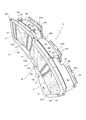
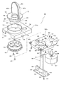
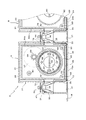
本発明では、遊技盤2面であって前記可変表示装置4の一側上方に電飾装置群Dとして3個の電飾装置A,B,Cが横並びに配設される。これら電飾装置A,B,Cはいずれも同じ構成からなる。図2は電飾装置群の斜視図、図3は同分解斜視図、図4は回転ユニットの分解斜視図、図5は電飾装置の平面断面図、図6は図5のX−X線断面図、図7は図6のY−Y線断面図をそれぞれ示す。   In the present invention, three illumination devices A, B, and C are arranged side by side as an illumination device group D on the game board 2 surface and above one side of the variable display device 4. All of these illumination devices A, B, and C have the same configuration. 2 is a perspective view of the electrical decoration device group, FIG. 3 is an exploded perspective view thereof, FIG. 4 is an exploded perspective view of the rotating unit, FIG. 5 is a plan sectional view of the electrical decoration device, and FIG. Sectional drawing and FIG. 7 show the YY sectional view taken on the line of FIG.

電飾装置群Dは、遊技盤2面に取り付けられる合成樹脂材からなる正面横長状の透明な取付板18を有する。該取付板18には、3個の略方形状の透孔19,19,19が開設され、取付板18の後面に下方を除いて各透孔19,19,19の周囲を囲う合成樹脂製の側枠20が一体に設けられている。また、各透孔19の一側裏面には、凹凸面21が成形されこの部位を通過する光が拡散されるようにしている。22は取付板18の適宜個所に設けられた取付用孔である。   The electrical decoration device group D has a front horizontally long transparent mounting plate 18 made of a synthetic resin material that is attached to the two game boards. The mounting plate 18 has three substantially rectangular through holes 19, 19, 19, and is made of a synthetic resin that surrounds each of the through holes 19, 19, 19 except for the lower part on the rear surface of the mounting plate 18. The side frame 20 is integrally provided. In addition, an uneven surface 21 is formed on the back surface of each through hole 19 so that light passing through this portion is diffused. Reference numeral 22 denotes a mounting hole provided at an appropriate location on the mounting plate 18.

前記各透孔19には、裏側から適宜色、この場合、図2で向かって左が赤色、真中がオレンジ色、右が黄色にそれぞれ着色された透光性の合成樹脂製のカバー部材23a,23b,23cが嵌着される。各カバー部材23a,23b,23cは、各透孔19に合致する大きさを有し、各前板24の上縁と両側縁に後方へ突出する囲い片25が一体に設けられている。各前板24の後面には、透明な板状のレンズ板26が添着される。   Each of the through holes 19 has an appropriate color from the back side, and in this case, in FIG. 2, a cover member 23a made of a light-transmitting synthetic resin colored in red on the left, orange in the middle, and yellow on the right, respectively. 23b and 23c are fitted. Each of the cover members 23a, 23b, and 23c has a size that matches each of the through holes 19, and is integrally provided with a surrounding piece 25 that protrudes rearward from the upper edge and both side edges of each front plate 24. A transparent plate-like lens plate 26 is attached to the rear surface of each front plate 24.

前記取付板18の後側に該取付板18の後側を覆う合成樹脂製の後部枠27が配置される。該後部枠27は、その外周面全体が銀色に樹脂メッキされ、前記各透孔19に対応位置してそれぞれ後方へ椀状に窪ませた第2反射板28が設けられ、各第2反射板28の前側にそれぞれ3個の収容部29,29,29が成形される。各第2反射板28のほぼ中央部には、上下左右にそれぞれ位置させて円形状の通孔30が開設される。各通孔30は、後記するLED41a,41b,41cを後側から各収容部29に臨ませるためのものである。また、各収容部29には、それぞれ後記する回転ユニット53が配置固定されることになる。このため、前記各収容部29の第2反射板28の下部に更に後方へ窪む取付凹部31が凹設されており、各取付凹部31の前側両側縁の垂直面に軸受凹部32,32が設けられ、各取付凹部31の後端位置には各軸受凹部32,32よりやや下方に位置して水平な支持板33が突設される。   A synthetic resin rear frame 27 covering the rear side of the mounting plate 18 is disposed on the rear side of the mounting plate 18. The rear frame 27 is provided with a second reflector 28 whose entire outer peripheral surface is resin-plated in silver, and is recessed corresponding to each of the through-holes 19 in a bowl shape to the rear. Three accommodating portions 29, 29, 29 are formed on the front side of 28. A circular through-hole 30 is formed at a substantially central portion of each second reflecting plate 28 so as to be positioned vertically and horizontally. Each through-hole 30 is for allowing LEDs 41a, 41b, and 41c, which will be described later, to face each housing portion 29 from the rear side. In addition, a rotation unit 53 to be described later is arranged and fixed in each accommodating portion 29. For this reason, a mounting recess 31 that is further recessed rearward is formed in the lower portion of the second reflecting plate 28 of each housing portion 29, and bearing recesses 32, 32 are formed on the vertical surfaces of both front edges of each mounting recess 31. A horizontal support plate 33 is provided at a rear end position of each mounting recess 31 so as to be slightly below the bearing recesses 32, 32.

前記後部枠27の各収容部29に隣接する一側前面に、前記取付板18の各凹凸面21に対向位置して上下2個の通孔34,34が開設されている。また、前記各一側前面には合成樹脂製の副反射部材35が配置される。各副反射部材35は、前面が開放した縦長の箱状に成形され、その外周面全体が銀色に樹脂メッキされ鏡面になっている。各副反射部材35の後壁には、前記各通孔34,34に対応する副通孔36,36が開設される。また、各副反射部材35の後面にネジ孔37を有するボス38が突設される。   Two upper and lower through holes 34, 34 are opened on one side front surface adjacent to each accommodating portion 29 of the rear frame 27 so as to be opposed to each uneven surface 21 of the mounting plate 18. Further, a sub-reflection member 35 made of synthetic resin is disposed on the front surface of each one side. Each sub-reflection member 35 is formed in a vertically long box shape with the front surface open, and the entire outer peripheral surface thereof is plated with silver resin to form a mirror surface. Sub-through holes 36 and 36 corresponding to the through-holes 34 and 34 are formed in the rear wall of the sub-reflection member 35. In addition, a boss 38 having a screw hole 37 is provided on the rear surface of each sub-reflection member 35.

前記各副反射部材35を前記後部枠27の各一側面に当接した状態では、各副反射部材35の後面に突設したボス38が前記各一側面に設けられた開孔39を介して後方へ突出される。   In a state where each sub-reflection member 35 is in contact with each side surface of the rear frame 27, a boss 38 protruding from the rear surface of each sub-reflection member 35 is provided through an opening 39 provided on each side surface. It protrudes backward.

前記後部枠27の各第2反射板28の後側に配線基板40が配置される。各配線基板40は基板保持部材40aに取着され、各配線基板40の前面には前記各第2反射板28に開設された上と両横の3個の通孔30に対応位置しかつ該各通孔30から各収容部29内に臨む第2発光体としてのLED41a,41b,41cが配置されている。これらLED41a,41b,41cはいずれも白色に発光する。また、これら各LED41a,41b,41cを、各第2反射板28の内面28aから各収容部29内に突出位置させるようにしても良い。前記各下の通孔30には各配線基板40に取着されたコンデンサー42が臨むようになっている。前記各基板保持部材40aの両側部には、ネジ挿通孔43,43が設けられ、これらネジ挿通孔43,43を各第2反射板28の両側に突設したボス44のネジ孔45に合致させ、各ネジ挿通孔43,43を介して各ネジ孔45にネジ46を螺締することにより、各配線基板40が装着される。   A wiring board 40 is disposed on the rear side of each second reflecting plate 28 of the rear frame 27. Each wiring board 40 is attached to a board holding member 40a, and the front surface of each wiring board 40 is positioned on the front surface of each second reflecting plate 28 and corresponding to the three through holes 30 on both sides. LEDs 41 a, 41 b, 41 c as second light emitters that face the respective accommodating portions 29 from the respective through holes 30 are arranged. These LEDs 41a, 41b, and 41c all emit white light. Further, these LEDs 41 a, 41 b, 41 c may be protruded from the inner surface 28 a of each second reflecting plate 28 into each housing portion 29. A capacitor 42 attached to each wiring board 40 faces each of the lower through holes 30. Screw insertion holes 43, 43 are provided on both sides of each substrate holding member 40 a, and these screw insertion holes 43, 43 match the screw holes 45 of the bosses 44 projecting on both sides of each second reflector 28. Then, each wiring board 40 is mounted by screwing a screw 46 into each screw hole 45 through each screw insertion hole 43, 43.

また、後部枠27の後面であって、前記各副反射部材35の取付位置に対応させて副配線基板47が配置される。該各副配線基板47は、縦長に成形され、前面上下にそれぞれ前記各通孔34と副通孔36に対応位置しこれら通孔34と副通孔36を介して各副反射部材35の凹部内に臨むLED48,48が配置される。これらLED48,48は白色に発光する。各副配線基板47のほぼ中央部にネジ挿通孔49が開設される。そして、前記各副配線基板47のネジ挿通孔49を介してボス38のネジ孔37にネジ52を螺締めすることにより各副反射部材35と各副配線基板47と一体に装着される。   A sub-wiring board 47 is disposed on the rear surface of the rear frame 27 so as to correspond to the mounting positions of the sub-reflection members 35. Each of the sub-wiring boards 47 is formed in a vertically long shape, and is located in the upper and lower sides of the front surface so as to correspond to each of the through holes 34 and the sub through holes 36, respectively. LEDs 48, 48 facing inside are arranged. These LEDs 48 and 48 emit white light. A screw insertion hole 49 is formed at substantially the center of each sub wiring board 47. Then, each sub-reflection member 35 and each sub-wiring board 47 are mounted integrally by screwing a screw 52 into the screw hole 37 of the boss 38 through the screw insertion hole 49 of each sub-wiring board 47.

次に、回転ユニット53について説明する。該回転ユニット53は、平面略方形状をなす合成樹脂製の上枠体54aと同下枠体54bとを有し、下枠体54bの上板55のほぼ中央部に略半円状の開口56が開設されると共に一側角部に第1透孔57が開設される。また、下枠体54bの下側に第1発光体支持部材58が配置される。該第1発光体支持部材58は、水平に配置される台板59とその上面に立設される保持板60とからなり、該保持板60の上端部の一側面に第1発光体としてのLED61が取着される。このLED61は白色に発光する。そして、前記下枠体54bの下側から保持板60を開孔56に挿通し、台板59の隅角部に開設されたネジ挿通孔62を下枠体54bに設けられたネジ孔63に合致させると共に各ネジ挿通孔62を介して各ネジ孔63にネジ64を螺締めする。この際、下枠体54bの上板55の下面に突出するガイドピン65が前記台板59に開設されたガイド孔66に嵌合して位置決めできるようになっている。これにより、第1発光体支持部材58が下枠体54bに固着される。   Next, the rotation unit 53 will be described. The rotating unit 53 has an upper frame body 54a and a lower frame body 54b made of a synthetic resin having a substantially rectangular plane shape, and a substantially semicircular opening at a substantially central portion of the upper plate 55 of the lower frame body 54b. 56 is opened and a first through hole 57 is opened at one corner. The first light emitter support member 58 is disposed below the lower frame body 54b. The first light emitter support member 58 includes a horizontally disposed base plate 59 and a holding plate 60 standing on the upper surface thereof. LED 61 is attached. The LED 61 emits white light. Then, the holding plate 60 is inserted into the opening 56 from the lower side of the lower frame body 54b, and the screw insertion holes 62 formed in the corners of the base plate 59 are inserted into the screw holes 63 provided in the lower frame body 54b. At the same time, the screws 64 are screwed into the screw holes 63 through the screw insertion holes 62. At this time, a guide pin 65 protruding from the lower surface of the upper plate 55 of the lower frame body 54b can be fitted and positioned in a guide hole 66 formed in the base plate 59. Thereby, the first light emitter support member 58 is fixed to the lower frame body 54b.

また、前記上板55の第1透孔57側の下側には正逆回転自在であって回転速度も変更できる駆動手段としてのモータ67が配置される。該モータ67には、その上面から上方へ突出する駆動軸68に駆動歯車69が設けられる。そして、上板55の下側から第1透孔57に駆動軸68を挿通すると共に駆動歯車69を上板55の上方に位置させた状態で、上板55に開設された一対のネジ挿通孔70,70を該各ネジ挿通孔70に対応してモータ67の上面に設けられた一対のネジ孔71,71に合致させ、各ネジ挿通孔70を介して各ネジ孔71にネジ72を螺締めする。これにより、モータ67が下枠体54bに固着される。   Further, a motor 67 as a driving means that can rotate forward and backward and can change the rotation speed is disposed below the first through hole 57 side of the upper plate 55. The motor 67 is provided with a drive gear 69 on a drive shaft 68 protruding upward from the upper surface thereof. A pair of screw insertion holes formed in the upper plate 55 in a state where the drive shaft 68 is inserted from the lower side of the upper plate 55 into the first through hole 57 and the drive gear 69 is positioned above the upper plate 55. 70 and 70 are matched with a pair of screw holes 71 and 71 provided on the upper surface of the motor 67 corresponding to each screw insertion hole 70, and a screw 72 is screwed into each screw hole 71 through each screw insertion hole 70. Tighten. Thereby, the motor 67 is fixed to the lower frame 54b.

一方、前記上枠体54aには、前記下枠体54bの開口56の中心を中心とする円孔73が開設され、該円孔73の外周縁に上方へ突出する円環状の環状枠74が周設されている。また、前記下枠体54bの上板55の第1透孔57に対応位置して第2透孔75が開設される。上枠体54aの両側面のほぼ中央部に軸ピン76が水平方向に突設されている。   On the other hand, a circular hole 73 centering on the center of the opening 56 of the lower frame body 54b is formed in the upper frame body 54a, and an annular ring frame 74 protruding upward at the outer peripheral edge of the circular hole 73 is formed. It is installed around. A second through hole 75 is opened at a position corresponding to the first through hole 57 of the upper plate 55 of the lower frame body 54b. A shaft pin 76 is projected in the horizontal direction at substantially the center of both side surfaces of the upper frame 54a.

前記環状枠74内には合成樹脂製の回転体77が遊嵌される。該回転体77は、中央に上中心孔78が開設されたドーナツ板状の回転板79を有する。この回転板79は、前記円形の環状枠74よりも外径が大きく、該環状枠74の上端縁に載るようになっている。そして、回転板79の上面に上中心孔78から位置をずらしかつその一側を囲うようにして第1反射板80が立設される。該第1反射板80は上中心孔78側の側面が弧面に窪ませてあり、その窪んだ内面80aと外面80b及び前記回転板79の外周面全体とが樹脂メッキされ鏡面に成形されている。前記回転板79の下面には、前記上中心孔78と同心円状に配置され上下両端面が開放した短筒体81が一体に設けられている。   A synthetic resin rotating body 77 is loosely fitted in the annular frame 74. The rotating body 77 has a donut plate-like rotating plate 79 having an upper center hole 78 formed in the center. The rotating plate 79 has an outer diameter larger than that of the circular annular frame 74 and is placed on the upper end edge of the annular frame 74. Then, the first reflecting plate 80 is erected on the upper surface of the rotating plate 79 so as to shift the position from the upper center hole 78 and surround one side thereof. The first reflecting plate 80 has a side surface on the side of the upper center hole 78 recessed in an arc surface, and the recessed inner surface 80a and outer surface 80b and the entire outer peripheral surface of the rotating plate 79 are resin-plated and formed into a mirror surface. Yes. On the lower surface of the rotating plate 79, a short cylinder 81 is provided integrally with the upper center hole 78, which is concentrically arranged and whose upper and lower end faces are open.

上枠体54aの下側であって前記円孔73の下方に従動歯車82が配置される。該従動歯車82は、中央部に前記上中心孔78と対向位置して下中心孔83が開設され、その上面に前記回転体77の短筒体81が遊嵌しかつ上枠体54aの環状枠74内に遊嵌する環状枠板部84が一体に設けられている。そして、従動歯車82を円孔73と対向して上枠体54aの下側に配置すると共に環状枠板部84を円孔73を介し環状枠74内に遊嵌する。この状態で、回転体77を環状枠74の上部に配置し、短筒体81を環状枠板部84内に遊嵌する。更に、従動歯車82における下中心孔83の外周部に設けられたネジ挿通孔85を短筒体81の下面に設けられたネジ孔86に合致させ、ネジ挿通孔85を介してネジ孔86にネジ87を螺締する。また、この際、前記短筒部81の下面に突設されたガイドピン88を従動歯車82に開設されたガイド孔89に嵌入させて位置決めするようにしている。このようにして、回転体77が上枠体54aに取り付けられる。   A driven gear 82 is disposed below the upper hole 54a and below the circular hole 73. The driven gear 82 is provided with a lower center hole 83 at a central portion so as to face the upper center hole 78, and a short cylinder 81 of the rotating body 77 is loosely fitted on the upper surface of the driven gear 82 and an annular shape of the upper frame 54a. An annular frame plate portion 84 that is loosely fitted in the frame 74 is integrally provided. Then, the driven gear 82 is disposed below the upper frame body 54 a so as to face the circular hole 73, and the annular frame plate portion 84 is loosely fitted into the annular frame 74 through the circular hole 73. In this state, the rotating body 77 is arranged on the upper portion of the annular frame 74, and the short cylinder 81 is loosely fitted in the annular frame plate portion 84. Further, the screw insertion hole 85 provided in the outer peripheral portion of the lower center hole 83 in the driven gear 82 is matched with the screw hole 86 provided in the lower surface of the short cylindrical body 81, and the screw hole 86 is inserted through the screw insertion hole 85. Screw 87 is screwed. At this time, a guide pin 88 projecting from the lower surface of the short cylindrical portion 81 is fitted into a guide hole 89 formed in the driven gear 82 to be positioned. In this way, the rotating body 77 is attached to the upper frame body 54a.

最後に、前記従動歯車82の下中心孔83及び回転体77の上中心孔78に前記保持板60を下側から挿通すると共に上枠体54aの下面に下枠体54bを重ね合わせる。そして、下枠体54bの上板55の適宜位置に設けられた複数のネジ挿通孔90とこれらと対向位置して上枠体54aに設けられた複数のボス91下端のネジ孔92とを合致させ、各ネジ挿通孔90を介して各ネジ孔92にネジ93を螺締めする。これにより、上枠体54aと下枠体54bとが一体に組みつけられる。そして、図7に示すようにモータ67の駆動歯車69と従動歯車82とが噛合し、モータ67の駆動により従動歯車82を介して回転体77が水平面内で正逆自在にまた回転速度を自在に変更して回転するようになり、保持板60の第1発光体であるLED61を中心にしてその周囲を第1反射板80が旋回することになる。   Finally, the holding plate 60 is inserted from the lower side into the lower center hole 83 of the driven gear 82 and the upper center hole 78 of the rotating body 77, and the lower frame body 54b is superimposed on the lower surface of the upper frame body 54a. Then, the plurality of screw insertion holes 90 provided at appropriate positions on the upper plate 55 of the lower frame body 54b and the screw holes 92 at the lower ends of the plurality of bosses 91 provided in the upper frame body 54a so as to be opposed to these are matched. Then, a screw 93 is screwed into each screw hole 92 via each screw insertion hole 90. Thereby, the upper frame body 54a and the lower frame body 54b are assembled together. Then, as shown in FIG. 7, the drive gear 69 of the motor 67 and the driven gear 82 are engaged with each other, and the rotating body 77 is freely reversible and freely rotatable in the horizontal plane via the driven gear 82 by the drive of the motor 67. The first reflecting plate 80 turns around the LED 61 that is the first light emitter of the holding plate 60.

このようにして組立てられた各回転ユニット53は、後部枠27の各取付凹部31に前側から挿入し、両軸ピン76,76を取付凹部31側の両軸受凹部32,32に嵌め込み、後端部を支持板33に受け止めさせてほぼ水平に支持される。この状態で、後部枠27の前面にカバー部材23a,23b,23cがそれぞれ装着された取付板18を合致させ、取付板18後側の適宜位置に設けられた複数のボス94後端のネジ孔95に該各ネジ孔95と対応位置して後部枠27に設けられたネジ挿通孔96を介してネジ97を螺締めして電飾装置群Dが完成する。電飾装置A,B,Cの各第1・第2発光体であるLED41a,41b,41c,61やモータ67は電気的に制御基板に接続され、遊技内容に合わせて制御される。   Each rotating unit 53 assembled in this way is inserted into each mounting recess 31 of the rear frame 27 from the front side, and both shaft pins 76 and 76 are fitted into both bearing recesses 32 and 32 on the mounting recess 31 side. The part is received by the support plate 33 and supported substantially horizontally. In this state, the mounting plate 18 to which the cover members 23a, 23b, and 23c are respectively attached is matched with the front surface of the rear frame 27, and screw holes at the rear ends of a plurality of bosses 94 provided at appropriate positions on the rear side of the mounting plate 18 The electrical decoration device group D is completed by screwing the screws 97 through the screw insertion holes 96 provided in the rear frame 27 at positions corresponding to the respective screw holes 95. The LEDs 41a, 41b, 41c, 61 and the motor 67, which are the first and second light emitters of the lighting devices A, B, C, are electrically connected to the control board and controlled according to the game content.

本発明に係る電飾装置A,B,Cは上記構成からなり、その作用について説明する。通常、図8のブロック図に示すようにパチンコ遊技機Pは遊技制御基板を初めとする各制御基板により制御されて遊技が進行する。図8中、パトランプとは本発明における電飾装置A,B,Cを示す。遊技中の前記電飾装置A,B,Cにおける第1発光体61又は第2発光体41a,41b,41cの点灯方法はいろいろあるが、その一例を図9のフローチャート図に従って説明する。   The electrical decoration devices A, B, and C according to the present invention have the above-described configuration, and their operation will be described. Normally, as shown in the block diagram of FIG. 8, the pachinko gaming machine P is controlled by each control board including the game control board, and the game proceeds. In FIG. 8, the patrol lamp indicates the electric decoration devices A, B, and C according to the present invention. There are various lighting methods of the first light emitters 61 or the second light emitters 41a, 41b, 41c in the lighting devices A, B, C during the game, and an example thereof will be described according to the flowchart of FIG.

図9中、パトランプA,B,Cは本発明の電飾装置A,B,Cを示す。そして、例えば、始動入賞口5に遊技球が入賞して可変表示装置4の表示部4aに表示される表示が変動すると共に途中で「7, ,7」の表示がなされ、続いて残りの中央に7がきて3つ揃えば遊技者に有利な大当たり状態になる。この大当たり状態になる前の所謂リーチ状態のとき、中央に「7」がきて大当たり状態となる期待度を前記各電飾装置A,B,Cがいくつ発光するかによって遊技者に知らせるようにしている。   In FIG. 9, patrol lamps A, B, and C indicate the electric decoration devices A, B, and C of the present invention. Then, for example, a game ball wins at the start winning opening 5 and the display displayed on the display unit 4a of the variable display device 4 changes, and “7,... 7” is displayed on the way, followed by the remaining center. If 7 comes to 3 and all three are arranged, it becomes a big hit state advantageous to the player. In the so-called reach state before the big hit state, the player is informed of the degree of expectation of the big hit state with “7” in the center depending on how many lighting devices A, B, and C emit light. Yes.

すなわち、図9において、前記リーチ状態になったときフラッシュ演出に当選すると、各パトランプA,B,Cの第2発光体であるLED41a,41b,41cが点灯又は点滅する。次に、パトランプ演出Aに当選するとパトランプAが回転すると共に第1発光体61が点灯する。同時に、パトランプ演出Bに当選するとパトランプBが回転すると共に第1発光体61が点灯する。同様に、パトランプ演出Cに当選するとパトランプCが回転すると共に第1発光体61が点灯する。途中、各演出が当選しないと、それ以上のパトランプは回転せず、第1発光体61も点灯しなくなる。   That is, in FIG. 9, when the flash effect is won in the reach state, the LEDs 41a, 41b, and 41c, which are the second light emitters of the patrol lamps A, B, and C, are lit or blinked. Next, when winning the patrol lamp effect A, the patrol lamp A rotates and the first light emitter 61 lights up. At the same time, when the patrol lamp effect B is won, the patrol lamp B rotates and the first light emitter 61 is turned on. Similarly, when the patrol lamp effect C is won, the patrol lamp C rotates and the first light emitter 61 is turned on. If each effect is not won, the patrol lamps will not rotate and the first light emitter 61 will not light up.

更に詳しく説明すると、前記フラッシュ演出に当選したとき、各電飾装置A,B,Cにおいて各第1反射板80は停止したままで、第2発光体である各LED41a,41b,41cが点灯又は点滅する。各LED41a,41b,41cからの光は図5、図6に示すように第1反射板80の鏡面である外面80bで反射すると共に第2反射板28で再び反射され、第1反射板80の外周縁側から間接的な光として前方へ照射される。 More specifically, when the flash effect is won, each LED 41a, 41b, 41c, which is the second light emitter, is turned on while each first reflector 80 is stopped in each of the lighting devices A, B, C. Flashes. As shown in FIGS. 5 and 6, the light from each LED 41 a, 41 b, 41 c is reflected by the outer surface 80 b which is the mirror surface of the first reflecting plate 80, and is reflected again by the second reflecting plate 28. Irradiated forward as indirect light from the outer periphery side.

また、この状態でパトランプ演出Aに当選すると、更に電飾装置Aの第1発光体であるLED61が発光すると共にモータ67が駆動して第1反射板80が旋回する。該第1反射板80が旋回している途中、該第1反射板80が第1発光体であるLED61の前側に位置し遊技者側から該第1発光体であるLED61の光が見えない場合は、第1発光体であるLED61の光及び第1反射板80の内面80aで反射した光が、第2反射板28の鏡面である内面28aに反射して第1反射板80の外周縁側から遊技者側へ間接的に照射される。同様に、第2発光体であるLED41a,41b,41cの光は第1反射板80の内面80aに反射しかつ第2反射板28の内面28aに反射して遊技者側へ間接的に照射される。   In addition, when the patrol lamp effect A is won in this state, the LED 61 as the first light emitter of the illumination device A further emits light, and the motor 67 is driven to turn the first reflector 80. While the first reflector 80 is turning, the first reflector 80 is positioned on the front side of the LED 61 that is the first light emitter, and the light of the LED 61 that is the first light emitter cannot be seen from the player side. The light of the LED 61 that is the first light emitter and the light reflected by the inner surface 80a of the first reflecting plate 80 are reflected by the inner surface 28a that is the mirror surface of the second reflecting plate 28 from the outer peripheral side of the first reflecting plate 80. Irradiated indirectly to the player. Similarly, the light from the LEDs 41a, 41b, and 41c, which are the second light emitters, is reflected on the inner surface 80a of the first reflecting plate 80 and is reflected on the inner surface 28a of the second reflecting plate 28 and indirectly irradiated to the player side. The

一方、該第1反射板80が旋回している途中、第1反射板80が第1発光体であるLED61の後側に位置し遊技者側から該第1発光体であるLED61の光が見える場合は、第1発光体であるLED61の光が直接遊技者側へ照射されると共に第1反射板80の内面80aで反射した光も遊技者側に照射される。また、第2発光体であるLED41a,41b,41cの光は、第1反射板80の外面80bに反射しかつ第2反射板28の内面28aで反射して間接的に遊技者側に照射される。いずれの場合も、第1発光体61の光及び第1反射板80の内面80aにより反射された光及び第2反射板28の内面28aで反射された光は、いずれも各カバー部材23a,23b,23cのレンズ板26を介して拡散され前方へ放射される。この場合、電飾装置Aのカバー部材23aからは赤色の光が放射される。また、電飾装置Bのカバー部材23bからはオレンジ色の光が放射される。更に、電飾装置Cのカバー部材23cからは黄色の光が放射されることになる。   On the other hand, while the first reflector 80 is turning, the first reflector 80 is positioned behind the LED 61 that is the first light emitter, and the light of the LED 61 that is the first light emitter can be seen from the player side. In this case, the light of the LED 61 that is the first light emitter is directly irradiated to the player side, and the light reflected by the inner surface 80a of the first reflecting plate 80 is also irradiated to the player side. The light from the LEDs 41a, 41b, and 41c, which are the second light emitters, is reflected on the outer surface 80b of the first reflecting plate 80 and is reflected on the inner surface 28a of the second reflecting plate 28 and indirectly irradiated to the player side. The In any case, the light of the first light emitter 61, the light reflected by the inner surface 80a of the first reflecting plate 80, and the light reflected by the inner surface 28a of the second reflecting plate 28 are both cover members 23a, 23b. , 23c is diffused through the lens plate 26 and emitted forward. In this case, red light is emitted from the cover member 23a of the electrical decoration device A. Further, orange light is emitted from the cover member 23b of the electrical decoration device B. Further, yellow light is emitted from the cover member 23c of the electrical decoration device C.

このように、電飾装置Aから電飾装置Cに至るように第1発光体61及び第2発光体41a,41b,41cが発光するに従い漸次大当たり状態になる期待度が上がるようにしており、これにより遊技の興趣が高められる。なお、この間、前記各電飾装置A,B,C間に配置された各副配線基板47のLED48,48も発光して電飾効果を高めるようにしている。   Thus, as the first light emitter 61 and the second light emitters 41a, 41b, 41c emit light from the decoration device A to the decoration device C, the expectation of gradually increasing the big hit state is increased. This enhances the fun of gaming. During this period, the LEDs 48 and 48 of the sub wiring boards 47 arranged between the respective lighting devices A, B and C are also lit to enhance the lighting effect.

また、図10に示すフローチャートは、前記リーチ状態になったとき、いずれか一つのパトランプA,B,Cを点灯させると共に回転させ、大当たり状態になる期待度をいずれのパトランプA,B,Cが点灯するかその点灯した色によって認識できるようにしたものである。例えば、パトランプAが赤色に点灯するよりもパトランプBがオレンジ色に点灯する、また、パトランプBがオレンジ色に点灯するよりもパトランプCが黄色に点灯するほうが大当たり状態になる期待度が高くなるようにしている。これらは、大当たりになる期待度を認識させる一つの手段であって、これに限定されるものではない。他に、各パトランプA,B,Cの前記モータ67の回転速度をそれぞれ異なる速度となるように制御し、第1反射板80の旋回速度が速ければ速いほど大当たり状態になる期待度が高くなるように設定することも可能である。例えば、各パトランプA,B,Cの前記モータ67の回転速度をそれぞれ順に速くし、第1反射板80の旋回速度が速いパトランプが点灯すると期待度が高いようにしても良い。これにより、各パトランプA,B,Cの発光色による変化だけでなく、パトランプの回転速度との組み合わせにより複雑な演出・大当たり予告として機能させることができ、遊技の興趣を高めることができる。   Further, in the flowchart shown in FIG. 10, when reaching the reach state, any one of the patrol lamps A, B, and C is turned on and rotated, and the expectation level for the big hit state is determined by any of the patrol lamps A, B, and C. It lights up or can be recognized by its lit color. For example, when the patrol lamp B is lit in orange rather than when the patrol lamp A is lit in red, and when the patrol lamp C is lit in yellow than when the patrol lamp B is lit in orange, the expectation that the big hit state is higher. I have to. These are one means for recognizing the degree of expectation that will be a big hit, and the present invention is not limited to this. In addition, the rotational speeds of the motors 67 of the patrol lamps A, B, and C are controlled to be different from each other, and the higher the turning speed of the first reflecting plate 80, the higher the expectation that a big hit state will be achieved. It is also possible to set as follows. For example, the rotational speed of the motor 67 of each of the patrol lamps A, B, and C may be increased in order, and the expectation level may be increased when a patrol lamp with a fast turning speed of the first reflector 80 is lit. Thereby, not only the change by the luminescent color of each patrol lamp A, B, and C but it can be made to function as a complicated production | presentation and jackpot notice by combining with the rotational speed of a patrol lamp, and the interest of a game can be heightened.

本発明の前記説明では、電飾装置A,B,Cにおける第1発光体であるLED61、第2発光体である3個のLED41a,41b,41cとしていずれも白色に発光するLEDを使用したが、これは各カバー部材23a,23b,23cがそれぞれ異なる色に着色されているからである。仮に、各カバー部材23a,23b,23cがいずれも無色透明又は薄い乳白色であれば、前記第1発光体であるLED61と第2発光体である3個のLED41a,41b,41cとの少なくとも一方を発光する色が所望の色に自在に変えられる所謂フルカラーLEDとすることができる。これにより、カラフルな光を発光でき、遊技の興趣を高めることができる。また、各電飾装置A,B,Cにはそれぞれレンズ板26を装着したが、これにより第1・第2発光体であるLED41a,41b,41c,61から発せられる光が拡散され、発光量をより効果的に見せられるばかりでなく、各電飾装置A,B,Cを明るく煌びやかに発光させて遊技を盛り上げることができる。   In the above description of the present invention, the LEDs 61 that are the first light emitters and the three LEDs 41a, 41b, and 41c that are the second light emitters in the lighting devices A, B, and C are all LEDs that emit white light. This is because the cover members 23a, 23b, and 23c are colored in different colors. If each of the cover members 23a, 23b, and 23c is colorless and transparent or light milky white, at least one of the LED 61 as the first light emitter and the three LEDs 41a, 41b, and 41c as the second light emitter is used. A so-called full-color LED in which the light emission color can be freely changed to a desired color can be obtained. Thereby, colorful light can be emitted and the interest of the game can be enhanced. Further, each of the lighting devices A, B, and C is provided with a lens plate 26, whereby the light emitted from the LEDs 41a, 41b, 41c, and 61, which are the first and second light emitters, is diffused, and the light emission amount Can be shown more effectively, and each of the lighting devices A, B, and C can be brightly and brilliantly lit to excite the game.

本発明の各電飾装置A,B,Cにあっては、各第1・第2反射板28,80により光を反射させるようにしているので、発光量が多くなる。しかも、第1反射板80が第1発光体61の前側に位置し遊技者側から該第1発光体61の光が見えない場合であっても、第1発光体61の光及び第1反射板80の内面80aで反射した光は、第2反射板28の内面28aに反射して第1反射板80の外周縁側から遊技者側へ照射されるなど第1反射板80が旋回する途中での直接的な光の明暗の中に間接的な光が加わり極めて変化のある光の演出ができる。これにより、遊技の興趣が盛り上がる。   In each of the electrical decoration devices A, B, and C according to the present invention, since the light is reflected by the first and second reflectors 28 and 80, the light emission amount increases. In addition, even when the first reflector 80 is located on the front side of the first light emitter 61 and the light from the first light emitter 61 cannot be seen from the player side, the light and the first reflection of the first light emitter 61 are not observed. The light reflected by the inner surface 80a of the plate 80 is reflected by the inner surface 28a of the second reflecting plate 28 and irradiated from the outer peripheral edge side of the first reflecting plate 80 to the player side. Indirect light is added in the direct light brightness and darkness, and the production of extremely varied light can be achieved. This excites the fun of gaming.

また、第1・第2発光体としてLED41a,41b,41c,61を使用し、更にレンズ板を装着しているので、少ない消費電力で済み経済的であるばかりか、電飾装置の小型化もモータなどの位置を考慮せずに簡単に行える。   In addition, since the LEDs 41a, 41b, 41c, 61 are used as the first and second light emitters and the lens plate is further mounted, the power consumption can be reduced and the size of the lighting device can be reduced. It can be done easily without considering the position of the motor.

更に、前記電飾装置は3個並設した場合を説明したが、該電飾装置の個数は1個、2個、4個またはそれ以上であっても良いことは勿論である。また、その個数によって、前記光の色、点灯方法が適宜選択される。   Furthermore, although the case where three said electrical decoration apparatuses were arranged in parallel was demonstrated, of course, the number of this electrical decoration apparatus may be 1, 2, 4, or more. Further, the color of the light and the lighting method are appropriately selected depending on the number of the lights.

本発明が適用されるパチンコ遊技機の正面図。1 is a front view of a pachinko gaming machine to which the present invention is applied. 本発明に係る電飾装置群の斜視図。The perspective view of the electrical decoration apparatus group which concerns on this invention. 同分解斜視図。The exploded perspective view. 回転ユニットの分解斜視図。The exploded perspective view of a rotation unit. 電飾装置の平面断面図。The plane sectional view of an electrical decoration device. 図5のX−X線断面図。XX sectional drawing of FIG. 図6のY−Y線断面図。The YY sectional view taken on the line of FIG. ブロック図Block Diagram 遊技状態を説明するフローチャート図。The flowchart figure explaining a gaming state. 遊技状態を説明するフローチャート図。The flowchart figure explaining a gaming state.

符号の説明Explanation of symbols

23a〜23c カバー部材
28 第2反射板
28a 内面
41a〜41c 第2発光体(LED)
61 第1発光体(LED)
67 駆動手段(モータ)
80 第1反射板
80a 内面
80b 外面
D 電飾装置群
A 電飾装置
B 電飾装置
C 電飾装置
P パチンコ遊技機
23a-23c Cover member 28 Second reflector 28a Inner surface 41a-41c Second light emitter (LED)
61 First light emitter (LED)
67 Drive means (motor)
80 1st reflector 80a Inner surface 80b Outer surface D Decorating device group A Decorating device B Decorating device C Decorating device P Pachinko machine

Claims (4)

遊技機の所望位置に配置される電飾装置群であって、
前記電飾装置群は透明な取付板に沿って配置される複数の電飾装置を備え、
前記各電飾装置は、LEDからなる第1発光体と、駆動手段により前記第1発光体の周囲を内面が該第1発光体と対向するようにして旋回し該内面と外面とが鏡面である第1反射板と、前記第1反射板の周囲一側に該第1反射板を囲むように配置されると共に前記第1反射板と対向する内面が鏡面である第2反射板と、前記第2反射板側に複数個配置され発光して第1反射板側を照射するLEDからなる第2発光体と、前記第1反射板の周囲他側に配置される透光性のカバー部材とを有し、
前記取付板には前記各カバー部材が嵌合される透孔を開設すると共に前記各透孔一側の取付板の裏面に凹凸面を形成し、前記各凹凸面の裏側に対向位置して前面が開放すると共に外周面全体が鏡面になっている副反射部材を配置し、前記各副反射部材の凹部内に臨んで発光するLEDを配置したことを特徴とする遊技機の電飾装置群。
A group of electrical devices arranged at a desired position of a gaming machine,
The lighting device group includes a plurality of lighting devices arranged along a transparent mounting plate,
Each of the illumination devices is rotated by a first light emitter composed of LEDs and a driving means so that the inner surface of the first light emitter is opposed to the first light emitter, and the inner surface and the outer surface are mirror surfaces. A first reflecting plate, a second reflecting plate disposed on one side of the first reflecting plate so as to surround the first reflecting plate, and having an inner surface facing the first reflecting plate as a mirror surface; A plurality of second light emitters arranged on the second reflector side, each of which emits light and irradiates the first reflector side, and a translucent cover member arranged on the other side of the first reflector. Have
The mounting plate is provided with a through hole into which the cover member is fitted, and a concave and convex surface is formed on the back surface of the mounting plate on one side of the through hole. An electrical decoration device group for a gaming machine, in which a sub-reflective member whose outer peripheral surface is a mirror surface is disposed and an LED that emits light is disposed in the recess of each sub-reflective member.
前記各電飾装置における前記透光性のカバー部材が有彩色でありかつ前記第1発光体と前記第2発光体とが白色に発光するLEDである請求項1記載の遊技機の電飾装置群 2. The electrical decoration device for a gaming machine according to claim 1, wherein the translucent cover member in each of the electrical decoration devices is a chromatic color LED and the first light emitter and the second light emitter emit white light. Group . 前記各電飾装置における前記透光性のカバー部材が透明でありかつ前記第1発光体と前記第2発光体との少なくとも一方が色を自在に変えて発光するLEDである請求項1記載の遊技機の電飾装置群2. The LED according to claim 1, wherein the translucent cover member in each of the electrical decoration devices is transparent, and at least one of the first light emitter and the second light emitter is an LED that changes its color freely. A group of electrical equipment for gaming machines . 前記最初の電飾装置から最後の電飾装置に至るように第1発光体及び第2発光体が発光するに従い遊技者に有利な大当り状態になる期待度が漸次上がるようにした請求項1乃至3のうちのいずれか一つに記載の遊技機の電飾装置群 The expectation that the big hit state advantageous to the player is gradually increased as the first light emitter and the second light emitter emit light from the first lighting device to the last lighting device. The electrical equipment group of the gaming machine according to any one of the three .
JP2006004981A 2006-01-12 2006-01-12 Amusement machine lighting equipment group Expired - Fee Related JP4384122B2 (en)

Priority Applications (1)

Application Number Priority Date Filing Date Title
JP2006004981A JP4384122B2 (en) 2006-01-12 2006-01-12 Amusement machine lighting equipment group

Applications Claiming Priority (1)

Application Number Priority Date Filing Date Title
JP2006004981A JP4384122B2 (en) 2006-01-12 2006-01-12 Amusement machine lighting equipment group

Publications (2)

Publication Number Publication Date
JP2007185302A JP2007185302A (en) 2007-07-26
JP4384122B2 true JP4384122B2 (en) 2009-12-16

Family

ID=38340884

Family Applications (1)

Application Number Title Priority Date Filing Date
JP2006004981A Expired - Fee Related JP4384122B2 (en) 2006-01-12 2006-01-12 Amusement machine lighting equipment group

Country Status (1)

Country Link
JP (1) JP4384122B2 (en)

Families Citing this family (22)

* Cited by examiner, † Cited by third party
Publication number Priority date Publication date Assignee Title
JP5023370B2 (en) * 2007-08-09 2012-09-12 株式会社三共 Game machine
JP5148956B2 (en) * 2007-09-18 2013-02-20 株式会社大一商会 Game machine
JP5148957B2 (en) * 2007-09-18 2013-02-20 株式会社大一商会 Game machine
JP2009089830A (en) * 2007-10-05 2009-04-30 Okumura Yu-Ki Co Ltd Game machine
JP5151381B2 (en) * 2007-10-11 2013-02-27 奥村遊機株式会社 Revolving light for gaming machines
JP5084028B2 (en) * 2008-01-22 2012-11-28 サミー株式会社 Bullet ball machine
JP2009178355A (en) * 2008-01-31 2009-08-13 Abilit Corp Game machine
JP5166093B2 (en) * 2008-03-27 2013-03-21 株式会社オリンピア Game machine
JP5313558B2 (en) * 2008-06-17 2013-10-09 株式会社足立ライト工業所 Fluctuation display device for gaming machine
JP2010012026A (en) * 2008-07-03 2010-01-21 Toyomaru Industry Co Ltd Game machine
JP2010012025A (en) * 2008-07-03 2010-01-21 Toyomaru Industry Co Ltd Game machine
JP5207049B2 (en) * 2008-08-06 2013-06-12 豊丸産業株式会社 Lighting device and game machine
JP5207050B2 (en) * 2008-08-06 2013-06-12 豊丸産業株式会社 Lighting device and game machine
JP2010051530A (en) * 2008-08-28 2010-03-11 Toyomaru Industry Co Ltd Game machine
JP2010051527A (en) * 2008-08-28 2010-03-11 Toyomaru Industry Co Ltd Game machine
JP5630687B2 (en) * 2010-05-06 2014-11-26 株式会社大一商会 Game machine
JP5049370B2 (en) * 2010-05-14 2012-10-17 京楽産業.株式会社 Light emitting unit
JP5422541B2 (en) * 2010-11-19 2014-02-19 株式会社ニューギン Game machine
JP5930587B2 (en) * 2011-02-23 2016-06-08 株式会社平和 Game machine
JP5677278B2 (en) * 2011-12-02 2015-02-25 京楽産業.株式会社 Game machine
JP2012066150A (en) * 2012-01-13 2012-04-05 Fujishoji Co Ltd Game machine
JP6281110B2 (en) * 2016-06-15 2018-02-21 株式会社ソフイア Game machine

Also Published As

Publication number Publication date
JP2007185302A (en) 2007-07-26

Similar Documents

Publication Publication Date Title
JP4384122B2 (en) Amusement machine lighting equipment group
JP4688562B2 (en) Amusement machine lighting equipment
JP4688563B2 (en) Amusement machine lighting equipment
JP4814972B2 (en) Game machine
JP2005013628A (en) Auxiliary performance device for game machine
JP2009219720A (en) Rotary lamp device
JP4803585B2 (en) Electrical equipment for bullet ball machines
JP2000157711A (en) Game machine
JP2010253190A (en) Game machine
JP2009090027A (en) Revolving light for game machine
JP2004008477A (en) Game machine
JP2002346064A (en) Game machine equipped with illumination device
JP2009136466A (en) Performance display device
JP2008000511A (en) Pachinko game machine
JP4512719B2 (en) Game machine
JP2007037944A (en) Display device for game machine
JP2002360837A (en) Game machine and illuminator for rotary motor-driven role object for throttle
JP2006346332A (en) Mirror ball device and game machine with mirror ball
JP2009142523A (en) Performance display device
JP2006087572A (en) Illumination device
JP2005237848A (en) Game machine
JP5354799B2 (en) Revolving light device for gaming machine
JP5375767B2 (en) Revolving light
JP2009082381A (en) Pattern display device and game machine mounting the same
JP2007151923A (en) Lighting device for game machine

Legal Events

Date Code Title Description
A977 Report on retrieval

Free format text: JAPANESE INTERMEDIATE CODE: A971007

Effective date: 20090114

A131 Notification of reasons for refusal

Free format text: JAPANESE INTERMEDIATE CODE: A131

Effective date: 20090127

A521 Written amendment

Free format text: JAPANESE INTERMEDIATE CODE: A523

Effective date: 20090326

TRDD Decision of grant or rejection written
A01 Written decision to grant a patent or to grant a registration (utility model)

Free format text: JAPANESE INTERMEDIATE CODE: A01

Effective date: 20090908

A01 Written decision to grant a patent or to grant a registration (utility model)

Free format text: JAPANESE INTERMEDIATE CODE: A01

A61 First payment of annual fees (during grant procedure)

Free format text: JAPANESE INTERMEDIATE CODE: A61

Effective date: 20090924

FPAY Renewal fee payment (event date is renewal date of database)

Free format text: PAYMENT UNTIL: 20121002

Year of fee payment: 3

R150 Certificate of patent or registration of utility model

Free format text: JAPANESE INTERMEDIATE CODE: R150

FPAY Renewal fee payment (event date is renewal date of database)

Free format text: PAYMENT UNTIL: 20151002

Year of fee payment: 6

R250 Receipt of annual fees

Free format text: JAPANESE INTERMEDIATE CODE: R250

LAPS Cancellation because of no payment of annual fees