JP4244389B2 - Clean room equipment - Google Patents
Clean room equipment Download PDFInfo
- Publication number
- JP4244389B2 JP4244389B2 JP2006252873A JP2006252873A JP4244389B2 JP 4244389 B2 JP4244389 B2 JP 4244389B2 JP 2006252873 A JP2006252873 A JP 2006252873A JP 2006252873 A JP2006252873 A JP 2006252873A JP 4244389 B2 JP4244389 B2 JP 4244389B2
- Authority
- JP
- Japan
- Prior art keywords
- air
- shutter
- clean
- opening
- clean room
- Prior art date
- Legal status (The legal status is an assumption and is not a legal conclusion. Google has not performed a legal analysis and makes no representation as to the accuracy of the status listed.)
- Expired - Fee Related
Links
Images


Landscapes
- Ventilation (AREA)
- Container, Conveyance, Adherence, Positioning, Of Wafer (AREA)
Description
この発明は、クリーンルーム内で物品の受け渡しに使用する装置に関し、特に開口を通しての物品の受け渡しを迅速に行うことに関する。 The present invention relates to an apparatus used for delivering an article in a clean room, and more particularly, to quickly delivering an article through an opening.
クリーンルーム内での処理装置間の物品の搬送には、無人搬送車や有軌道台車などが用いられている。処理装置とこれらの搬送台車の間で物品を受け渡しする前に、処理装置側のロードポートの開口と搬送台車の開口とを開いて、クリーンエアで処理装置と搬送台車の間の空気を置換する必要がある。 An automated guided vehicle, a tracked carriage, or the like is used for transporting articles between processing apparatuses in a clean room. Before delivering the article between the processing apparatus and these transport carts, the opening of the load port on the processing apparatus side and the opening of the transport cart are opened, and the air between the processing apparatus and the transport cart is replaced with clean air. There is a need.
図6に、従来例での処理装置2と搬送台車の間の空気の置換を示す。4は無人搬送車で搬送台車の例で、8,10はシャッタでこれらを同期して徐々に開くことにより、クリーンエアで処理装置と搬送台車の間の空気を置換する。しかしながら図6のようにクリーンエアを吹き出させると、空気の置換に時間がかかり、受け渡しが遅くなる。なお特許文献1は、無人搬送車の車体から処理装置などの側へ、常時空気を吹き出すことを開示している。
この発明の課題は、搬送台車と処理装置の間の空気をクリーンなガスで速やかに置換し、物品の受け渡し前の待ち時間を短縮することにある。
請求項2の発明での追加の課題は、搬送台車と処理装置間の空気をクリーンなガスで押し出し、より短時間で物品の受け渡しができるようにすることにある。
請求項3の発明での追加の課題は、搬送台車と処理装置間に多量のクリーンなガスを供給できるようにすることにある。
An object of the present invention is to quickly replace the air between the transport carriage and the processing apparatus with clean gas, and to shorten the waiting time before delivery of the article.
An additional problem in the invention of
An additional problem in the invention of claim 3 is that a large amount of clean gas can be supplied between the transport carriage and the processing apparatus.
この発明は、物品の受け渡し用の開口と、開口を開閉するシャッタと、開口の内部にクリーンなガスを供給するための手段とを備えたクリーンルーム内装置であって、クリーンなガスを外部へ吹き出させるための吹出口をシャッタに設けたことを特徴とする。クリーンなガスはクリーンエアやクリーンな窒素ガスなどとする。 The present invention relates to an apparatus in a clean room comprising an opening for delivering articles, a shutter for opening and closing the opening, and a means for supplying clean gas into the opening, and the clean gas is blown out to the outside. A blower outlet is provided in the shutter. Clean gas is clean air or clean nitrogen gas.
好ましくは、吹出口を前記シャッタが開口を覆う面の中心部付近に設ける。なお吹出口の位置はシャッタが前記開口を覆う面の中心部付近に有れば良く、正確に中心に有る必要は無く、例えば面の上下方向の幅と水平方向の幅との10%程度、面の中心からシフトしていても良い。 Preferably, the air outlet is provided near the center of the surface where the shutter covers the opening. The position of the air outlet is only required to be near the center of the surface where the shutter covers the opening, and does not need to be exactly at the center, for example, about 10% of the vertical and horizontal widths of the surface, It may be shifted from the center of the surface.
好ましくは、クリーンルーム内装置がクリーンルーム内に固定の装置で、搬送台車との間で物品を受け渡しする。 Preferably, the device in the clean room is a device fixed in the clean room, and delivers articles to and from the transport carriage.
この発明では、シャッタと物品の受け渡し相手との間の空気を、吹出口からのクリーンなガスで置換するので、物品の受け渡し前の待ち時間を短縮できる。 In this invention, since the air between the shutter and the delivery partner of the article is replaced with clean gas from the outlet, the waiting time before delivery of the article can be shortened.
請求項2の発明では、シャッタのほぼ中央部からクリーンなガスを供給して、物品の受け渡し相手との間の空気を追い出すので、効率的にクリーンなガスで雰囲気を置換でき、待ち時間をより短縮できる。 According to the second aspect of the present invention, clean gas is supplied from the substantially central portion of the shutter to expel air between the article delivery partner, so that the atmosphere can be efficiently replaced with clean gas, and waiting time can be further increased. Can be shortened.
請求項3の発明では、クリーンルーム内に固定の装置からクリーンなガスを供給するので、搬送台車などからクリーンなガスを供給する場合に比べ、より簡単に大流量のクリーンなガスを供給できる。 In the invention of claim 3, since clean gas is supplied from a fixed device into the clean room, clean gas with a large flow rate can be supplied more easily than when clean gas is supplied from a transport carriage or the like.
以下に本発明を実施するための最適実施例を示す。 In the following, an optimum embodiment for carrying out the present invention will be shown.
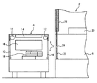
図1〜図5に、実施例とその変形とを示す。各図において、2はクリーンルーム内の処理装置で、4は無人搬送車であり、有軌道台車などでも良く、処理装置2には無人搬送車4との間で物品16を受け渡すためのロードポート6が設けてある。無人搬送車4には、物品16を受け渡しするための開口が走行方向の左右に設けられ、シャッタ10をローラ12で巻き取り/繰り出すことにより開口を開閉する。14はファンフィルタユニットで、無人搬送車4内にクリーンエアを供給し、16は受け渡し対象の物品で、例えば液晶基板や半導体,レチクルなどのカセットである。18はスカラアームなどの移載装置である。
1 to 5 show an embodiment and its modifications. In each figure, 2 is a processing device in a clean room, 4 is an automatic guided vehicle, and may be a tracked carriage, etc., and a load port for delivering an
ロードポート6内にはファンフィルタユニット20からクリーンエアが供給され、クリーンエアに代えて、クリーンな窒素などのガスを供給しても良い。ロードポート6の開口面はシャッタ22で覆われ、開口面の中央部の例えば1箇所に吹出口24が設けられ、開閉装置26によりシャッタ22が上方に移動すると、ロードポート6が開く。なお無人搬送車4がロードポート6に到着した際にのみ吹出口24を開くように、吹出口24を開閉するシャッタなどを設けても良い。また処理装置2に代えて検査装置やストッカなどでも良く、無人搬送車4に代えて有軌道台車などでも良い。
Clean air is supplied into the
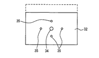
図2はシャッタ22を正面から見た姿を示し、点線内の領域はシャッタ22が開閉装置26内にあるため、ロードポート6の開口面から外れた領域を示している。そして吹出口24は、シャッタ22内で、ロードポート6の開口面のほぼ中央部に有るが、厳密に中央部に有る必要はない。
FIG. 2 shows the
図3に変形例のシャッタ32を示し、ロードポートの開口面のほぼ中央部で、シャッタ32に吹出口34を設け、その周囲に複数個の吹出口35を設けている。中央の吹出口34の開口面積は周囲の吹出口35の個々の開口面積よりも大きくしてある。
FIG. 3 shows a
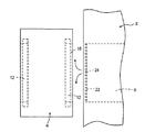
図4に、第2の変形例のシャッタ42を示す。シャッタ42では、ロードポートの開口面のほぼ全面に、例えば碁盤目状に多数個の吹出口44を設けてある。
FIG. 4 shows a
図1,図5により、実施例での吹出口24の動作を説明する。ロードポート6内にはファンフィルタユニット20から常時クリーンエアが供給されており、吹出口24から常時クリーンエアが吹き出している。無人搬送車4が到着すると、シャッタ22の中央部の吹出口24からのクリーンエアは、無人搬送車4のシャッタ10側に噴出して上下左右に分かれ、ロードポート6と無人搬送車4との間の空気をクリーンエアで押し出すようにして置換する。
The operation of the
吹出口24はロードポート6の開口面の中央部にあり、ここからクリーンエアが上下左右に拡がると、最も効率的にシャッタ10,22間の空気をクリーンエアで置換できる。これに対して図3のシャッタ32の場合、中央部の吹出口34以外に周囲の吹出口35が有るので、吹出口34からのクリーンエアが上下左右に拡がり難くなり、シャッタ32,10間の空気を置換するのに要する時間がやや長くなる。図4の変形例の場合、シャッタ42に碁盤目上に配置した周辺の開口からのクリーンエアは、無人搬送車4側に達して上下左右に拡がりやすいが、シャッタ42の中央部の吹出口からのクリーンエアは、周辺の吹出口からのクリーンエアの気流のため吹き出し難くなり、シャッタ42の中央部付近の空気の置換が遅れる。
The
吹出口24等からのクリーンエアにより、処理装置2と無人搬送車4間の空気をクリーンエアで置換できると、例えばシャッタ22,10の開閉速度を増して、より短時間で物品16を受け渡しできる。このため物品の受け渡しまでの待ち時間を短縮できる。また処理装置2側からクリーンエアを吹き出させるので、無人搬送車4側から吹き出せる場合に比べより大流量のクリーンエアを吹き出すことができる。
If the air between the
2 処理装置
4 無人搬送車
6 ロードポート
8,10 シャッタ
12 ローラ
14,20 ファンフィルタユニット
16 物品
18 移載装置
22,32,42 シャッタ
24,34,35,44 吹出口
26 開閉装置
2 Processing device 4 Automatic guided
Claims (3)
クリーンなガスを外部へ吹き出させるための吹出口を前記シャッタに設けたことを特徴とする、クリーンルーム内装置。 A device in a clean room comprising an opening for delivering an article, a shutter for opening and closing the opening, and means for supplying clean gas into the opening,
An apparatus in a clean room, characterized in that an air outlet for blowing out clean gas to the outside is provided in the shutter.
The device in a clean room according to claim 1 or 2, wherein the device in the clean room is a device fixed in the clean room.
Priority Applications (2)
| Application Number | Priority Date | Filing Date | Title |
|---|---|---|---|
| JP2006252873A JP4244389B2 (en) | 2006-09-19 | 2006-09-19 | Clean room equipment |
| TW96134286A TW200901351A (en) | 2006-09-19 | 2007-09-13 | Apparatus inside clean room |
Applications Claiming Priority (1)
| Application Number | Priority Date | Filing Date | Title |
|---|---|---|---|
| JP2006252873A JP4244389B2 (en) | 2006-09-19 | 2006-09-19 | Clean room equipment |
Publications (2)
| Publication Number | Publication Date |
|---|---|
| JP2008078198A JP2008078198A (en) | 2008-04-03 |
| JP4244389B2 true JP4244389B2 (en) | 2009-03-25 |
Family
ID=39349999
Family Applications (1)
| Application Number | Title | Priority Date | Filing Date |
|---|---|---|---|
| JP2006252873A Expired - Fee Related JP4244389B2 (en) | 2006-09-19 | 2006-09-19 | Clean room equipment |
Country Status (2)
| Country | Link |
|---|---|
| JP (1) | JP4244389B2 (en) |
| TW (1) | TW200901351A (en) |
Families Citing this family (1)
| Publication number | Priority date | Publication date | Assignee | Title |
|---|---|---|---|---|
| JP4706938B2 (en) * | 2008-11-21 | 2011-06-22 | 村田機械株式会社 | Clean room automatic warehouse and how to store goods in automatic warehouse |
-
2006
- 2006-09-19 JP JP2006252873A patent/JP4244389B2/en not_active Expired - Fee Related
-
2007
- 2007-09-13 TW TW96134286A patent/TW200901351A/en not_active IP Right Cessation
Also Published As
| Publication number | Publication date |
|---|---|
| TW200901351A (en) | 2009-01-01 |
| TWI376002B (en) | 2012-11-01 |
| JP2008078198A (en) | 2008-04-03 |
Similar Documents
| Publication | Publication Date | Title |
|---|---|---|
| TWI814621B (en) | porter room | |
| JP3788296B2 (en) | Goods storage equipment for clean rooms | |
| JP4756372B2 (en) | Substrate processing method | |
| US8757401B2 (en) | Article transport device | |
| JP2008068964A (en) | Substrate storage facility and substrate treatment facility | |
| TW200403791A (en) | Carrying vehicle, manufacturing apparatus, and carrying system | |
| JP2008094494A (en) | Storing container for storing substrate | |
| JP2013216446A (en) | Cleaning device | |
| TWI618899B (en) | Substrate transporting device, substrate treating apparatus, and substrate transporting method | |
| JP4029968B2 (en) | Transport vehicle, manufacturing apparatus and transport system | |
| JP4244389B2 (en) | Clean room equipment | |
| JP4187069B2 (en) | Substrate processing equipment | |
| JP4358077B2 (en) | Film forming apparatus and film forming method | |
| CN101276772A (en) | Stocker for semiconductor substrate | |
| JP3882139B2 (en) | Clean transport vehicle | |
| TWI649828B (en) | Substrate transfer system and heat treatment device using same | |
| JP2002110619A (en) | Substrate-treating apparatus | |
| JP2007269489A (en) | Article storage facility for clean room | |
| JP5467905B2 (en) | Film conveying apparatus and method, film manufacturing apparatus and method | |
| JP5049827B2 (en) | Mini-environment semiconductor manufacturing equipment | |
| JP2009126677A (en) | Carrying device | |
| JP4674574B2 (en) | Delivery device and system | |
| JP4126250B2 (en) | Transport system | |
| JP2009147163A (en) | Carriage | |
| JP2009126631A (en) | Storage warehouse facility |
Legal Events
| Date | Code | Title | Description |
|---|---|---|---|
| TRDD | Decision of grant or rejection written | ||
| A01 | Written decision to grant a patent or to grant a registration (utility model) |
Free format text: JAPANESE INTERMEDIATE CODE: A01 Effective date: 20081215 |
|
| A01 | Written decision to grant a patent or to grant a registration (utility model) |
Free format text: JAPANESE INTERMEDIATE CODE: A01 |
|
| A61 | First payment of annual fees (during grant procedure) |
Free format text: JAPANESE INTERMEDIATE CODE: A61 Effective date: 20081228 |
|
| R150 | Certificate of patent or registration of utility model |
Free format text: JAPANESE INTERMEDIATE CODE: R150 |
|
| FPAY | Renewal fee payment (event date is renewal date of database) |
Free format text: PAYMENT UNTIL: 20120116 Year of fee payment: 3 |
|
| FPAY | Renewal fee payment (event date is renewal date of database) |
Free format text: PAYMENT UNTIL: 20130116 Year of fee payment: 4 |
|
| FPAY | Renewal fee payment (event date is renewal date of database) |
Free format text: PAYMENT UNTIL: 20140116 Year of fee payment: 5 |
|
| R250 | Receipt of annual fees |
Free format text: JAPANESE INTERMEDIATE CODE: R250 |
|
| R250 | Receipt of annual fees |
Free format text: JAPANESE INTERMEDIATE CODE: R250 |
|
| R250 | Receipt of annual fees |
Free format text: JAPANESE INTERMEDIATE CODE: R250 |
|
| R250 | Receipt of annual fees |
Free format text: JAPANESE INTERMEDIATE CODE: R250 |
|
| LAPS | Cancellation because of no payment of annual fees |