JP4128748B2 - 髄内骨固定装置 - Google Patents
髄内骨固定装置 Download PDFInfo
- Publication number
- JP4128748B2 JP4128748B2 JP2000579139A JP2000579139A JP4128748B2 JP 4128748 B2 JP4128748 B2 JP 4128748B2 JP 2000579139 A JP2000579139 A JP 2000579139A JP 2000579139 A JP2000579139 A JP 2000579139A JP 4128748 B2 JP4128748 B2 JP 4128748B2
- Authority
- JP
- Japan
- Prior art keywords
- pin
- inner member
- hollow elongate
- elongate member
- hollow
- Prior art date
- Legal status (The legal status is an assumption and is not a legal conclusion. Google has not performed a legal analysis and makes no representation as to the accuracy of the status listed.)
- Expired - Fee Related
Links
- 210000000988 bone and bone Anatomy 0.000 title claims description 42
- 238000003780 insertion Methods 0.000 claims description 5
- 230000037431 insertion Effects 0.000 claims description 5
- 238000000034 method Methods 0.000 description 9
- 210000001624 hip Anatomy 0.000 description 4
- 210000000689 upper leg Anatomy 0.000 description 4
- 239000002639 bone cement Substances 0.000 description 2
- 210000003127 knee Anatomy 0.000 description 2
- 238000012986 modification Methods 0.000 description 2
- 230000004048 modification Effects 0.000 description 2
- 238000011084 recovery Methods 0.000 description 2
- 239000007787 solid Substances 0.000 description 2
- 230000006641 stabilisation Effects 0.000 description 2
- 238000011105 stabilization Methods 0.000 description 2
- 230000000087 stabilizing effect Effects 0.000 description 2
- 208000003149 Bone Malalignment Diseases 0.000 description 1
- 230000004075 alteration Effects 0.000 description 1
- 238000004873 anchoring Methods 0.000 description 1
- 238000013459 approach Methods 0.000 description 1
- 230000009286 beneficial effect Effects 0.000 description 1
- 239000004568 cement Substances 0.000 description 1
- 230000000295 complement effect Effects 0.000 description 1
- 210000004394 hip joint Anatomy 0.000 description 1
- 230000003993 interaction Effects 0.000 description 1
- 238000003754 machining Methods 0.000 description 1
- 230000014759 maintenance of location Effects 0.000 description 1
- 238000013508 migration Methods 0.000 description 1
- 230000005012 migration Effects 0.000 description 1
- 230000002980 postoperative effect Effects 0.000 description 1
- 238000001356 surgical procedure Methods 0.000 description 1
Images


Classifications
-
- A—HUMAN NECESSITIES
- A61—MEDICAL OR VETERINARY SCIENCE; HYGIENE
- A61B—DIAGNOSIS; SURGERY; IDENTIFICATION
- A61B17/00—Surgical instruments, devices or methods, e.g. tourniquets
- A61B17/56—Surgical instruments or methods for treatment of bones or joints; Devices specially adapted therefor
- A61B17/58—Surgical instruments or methods for treatment of bones or joints; Devices specially adapted therefor for osteosynthesis, e.g. bone plates, screws, setting implements or the like
- A61B17/68—Internal fixation devices, including fasteners and spinal fixators, even if a part thereof projects from the skin
- A61B17/72—Intramedullary pins, nails or other devices
- A61B17/7233—Intramedullary pins, nails or other devices with special means of locking the nail to the bone
- A61B17/7258—Intramedullary pins, nails or other devices with special means of locking the nail to the bone with laterally expanding parts, e.g. for gripping the bone
- A61B17/7266—Intramedullary pins, nails or other devices with special means of locking the nail to the bone with laterally expanding parts, e.g. for gripping the bone with fingers moving radially outwardly
-
- F—MECHANICAL ENGINEERING; LIGHTING; HEATING; WEAPONS; BLASTING
- F16—ENGINEERING ELEMENTS AND UNITS; GENERAL MEASURES FOR PRODUCING AND MAINTAINING EFFECTIVE FUNCTIONING OF MACHINES OR INSTALLATIONS; THERMAL INSULATION IN GENERAL
- F16B—DEVICES FOR FASTENING OR SECURING CONSTRUCTIONAL ELEMENTS OR MACHINE PARTS TOGETHER, e.g. NAILS, BOLTS, CIRCLIPS, CLAMPS, CLIPS OR WEDGES; JOINTS OR JOINTING
- F16B13/00—Dowels or other devices fastened in walls or the like by inserting them in holes made therein for that purpose
- F16B13/04—Dowels or other devices fastened in walls or the like by inserting them in holes made therein for that purpose with parts gripping in the hole or behind the reverse side of the wall after inserting from the front
- F16B13/10—Dowels or other devices fastened in walls or the like by inserting them in holes made therein for that purpose with parts gripping in the hole or behind the reverse side of the wall after inserting from the front with separate gripping parts moved into their final position in relation to the body of the device by a separate operation
Description
本発明は、髄内骨固定装置および髄内装置を骨に固定する方法に関するものである。本発明の装置および方法は、特に骨折部を安定させるため、および人工股関節、膝またはその他の関節などプロテーゼを骨に固定するために適している。
【0002】
骨折部の固定および安定は、特に長骨の場合難しい可能性がある。これには、通常2つの技法が使用される。第一の技法は、骨の一方のサイドにプレートを当て、複数のねじで骨折部の両側でプレートを骨に留める方法である。この技法は、骨の一方のサイドからだけねじを通じて骨に力が加えられるため、骨への負荷が不均等になる可能性があるという不利点がある。
【0003】
骨折部を固定し安定するための第二の技法は、骨の髄管に髄内ピンを挿入する方法である。固定ピンは使用する場合もしない場合もある。固定ピンを使用しない場合、骨折部の両側の骨が髄内ピンの周りで回転して骨の不整合を引き起こす可能性がある。固定ピンが使用される場合、骨折部の両側の骨に穴を穿ち、骨の穴および髄内ピンに形成される穴に固定ピンを挿入する必要がある。骨の穴と髄内ピンの穴とを整合させるのは困難であることが多く、そのため、手術手順が複雑化して、患者の術後回復時間を長くする可能性がある。
【0004】
人工股関節および人工膝などのプロテーゼの固定も同様の困難に直面している。例えば、人工股関節を患者に取り付けるためには、一般に、大腿上部を処置して、大腿の髄管に股関節プロテーゼのステム部分を挿入する。ステムは骨セメントによりまたは外部ピンを大腿に穿たれた穴および人工股関節のステム部分の穴に挿入することによって、大腿に固定される。外部ピンを使用することの難しさについては、上に説明した通りである。骨セメントが使用される場合、セメントが骨に適切に付着しない場合プロテーゼの不整合および移動を生じる可能性がある。
【0005】
先行技術の上記の不利点の一つまたはそれ以上を克服するまたは少なくとも改善する装置および方法を提供することが、本発明の目的である。
【0006】
第一の態様において本発明は、髄内骨固定装置であって、その側壁に少なくとも一つの開口を有し骨の髄管へ挿入するようにされた中空細長部材と、前記中空細長部材内に滑動可能に受容され得るサイズであり、少なくとも一本のピンを担持し、その外面に一つ以上の溝を有する内側部材と、を備え、前記少なくとも一本のピンは該少なくとも一本のピンが収縮位置にある時に前記一つ以上の溝内に位置せしめられ、少なくとも一本のピンはその一方の端で前記内側部材に旋回可能に接合され、前記少なくとも一本のピンは収縮位置から該少なくとも一本のピンが前記中空細長部材の少なくとも一つの開口のそれぞれを通って伸びる伸張位置へと移動可能であり、前記少なくとも一本のピンは、該少なくとも一本のピンの自由端を前記一つ以上の開口と整合させて配置し、前記内側部材を回転させてそれによって前記ピンが前記一つ以上の開口を通って伸びるようにすることによって前記伸張位置に移動される、装置を提供する。
【0007】
もう一つの態様において本発明は、髄内骨固定装置であって、その側壁に少なくとも一つの開口を有し骨の髄管へ挿入するようにされた中空細長部材と、前記中空細長部材内に滑動可能に受容され得るサイズであり、少なくとも一本のピンを担持している内側部材と、を備え、前記少なくとも一本のピンは収縮位置から該少なくとも一本のピンが前記中空細長部材の少なくとも一つの開口のそれぞれを通って伸びる伸張位置へと移動可能であり、前記少なくとも一本のピンはその一方の端に拡大部を有し、該拡大部は前記内側部材に形成されるそれぞれの穴または窪みに収まり、前記少なくとも一本のピンは収縮位置にある時に前記内側部材に形成されるそれぞれの溝に沿って伸び、前記一本以上のピンは前記中空細長部材の内壁によって所定の位置に保持されると共に、前記一本以上のピンはその自由端を前記中空細長部材の前記少なくとも一つの開口と整合させ前記内側部材を回転させることにより伸ばされる、装置を提供する。
【0008】
中空細長部材は、その遠位端に、中空細長部材を髄管に挿入しやすいように尖端または閉鎖端を持つことができる。中空細長部材の遠位端は、円錐形の尖端を備えることが望ましく、尖端は中空細長部材と一体で形成するか、中空細長部材に後から取り付けられる別個の部品として備えることができる。
【0009】
内側部材は中実部材であることが望ましいが、中空部材とすることもできる。内側部材は、中空細長部材にぴったりと合うが密着しすぎないサイズとすることにより、中空細長部材内で内側部材が容易に移動できるようにしながら、内側部材と中空細長部材の間にゆるみまたは「ルーズさ」が生じないようにすることが望ましい。内側部材および中空細長部材は共に、その長さの大部分が円筒形であることが望ましい。
【0010】
内側部材は少なくとも一本のピンを持つ。内側部材は、複数のピンを持つことが望ましい。中空細長部材は、少なくとも内側部材のピンと同じ数の開口をその側壁に持たなければならない。その代わりに、2本またはそれ以上のピンが通るように開口を形成することができる。例えば、中空細長部材は2本以上のピンが突き出せるスロットを備えることができる。
【0011】
一本またはそれ以上のピンは、本発明の装置を骨に対して相対的な所定の位置に保持する手段である。本発明の装置を使用する際、装置は骨の髄内管に挿入される。目標位置に達したら、ピンは収縮位置から伸張位置に移動する。伸張位置においては、各ピンは、中空細長部材の側壁の穴を通って骨の中まで伸びることによって、装置と骨の相対的位置を固定する。この装置は、外部固定ピンに合わせて骨に穴を穿つ必要がないので、使い方が単純である。また、骨を装置に対して相対的な位置にしっかりと保持する。
【0012】
本発明の望ましい実施態様においては、装置を骨にしっかりと固定または接合するために内側部材は複数のピンを持つ。説明の便宜上、本発明については、以後複数のピンを持つものとして説明する。しかし、本発明の目的は一本のピンによっても達成することができ、そのような実施態様も本発明の範囲内にあるものとする。
【0013】
収縮位置においては、ピンは、中空細長部材の外径または周辺を越えて伸びないことが望ましい。伸張位置においては、ピンは、中空細長部材の側壁の穴を通って骨の中まで伸びる。
【0014】
本発明の好ましい実施形態においては、内側部材は、その外面に一本またはそれ以上の溝を備える。この溝は、概ね横方向の溝が適切である。ピンは、溝に配置され、一端でまたはその付近で内側部材に旋回可能に接合される。各ピンの他方の端は、内側部材の面を僅かに越えて伸びることができる。ピンを伸張位置に移動させるために、内側部材は、ピンの自由端が中空細長部材の側壁の穴と整合すると回転させることができる。ピンの自由端は、この穴を通って伸びる。内側部材の回転が続く間、旋回可能に取り付けられたピンの端と中空細長部材の穴の間の距離は小さくなるので、ピンは完全に伸びるまで穴を通って外側に向かって動く。
【0015】
ピンが骨の中まで伸びるために必要な力で内側部材を回転させることができるように、内側部材の近位端は、ハンドルまたはトルクを与えるための手段と係合するための係合面を備えることができる。中空細長部材の回転を防止するためにまたはこれを最小限に抑えるために、中空細長部材を所定の位置に保持するための保持面も備えることができる。保持面は、中空細長部材の近位端の正方形、長方形、六角形またはその他の多角形面とすることができる。その代わりに、中空細長部材は、中空細長部材を所定の位置に保持するために適切なツールと係合するキー溝を備えることができる。
【0016】
中空細長部材および内側部材は、固定長さ部材でも、可変長さまたは調節可能長さの部材でもよい。可変長さまたは調節可能長さの部材は、装置が骨折部の固定に使用され骨折部の回復中装置の長さを調節することが望ましい場合、特に有益である。
【0017】
本発明は、その側壁に少なくとも一つの開口を有し骨の髄管に挿入するのに適する中空細長部材、およびこの中空細長部材内で滑動して受け入れられるサイズであり、少なくとも一本のピンを持ち、この少なくとも一本のピンが収縮位置から中空細長部材の少なくとも一つの開口のうちそれぞれ該当の開口を通って伸びる伸張位置に移動可能である内側部材を備える髄内骨固定装置を提供するステップ、髄内装置を骨の髄管に挿入するステップ、および少なくとも一本のピンを収縮位置から中空細長部材の側壁の少なくとも一つの開口のうちそれぞれ該当の開口を通って伸びる伸張ポジジョンまで伸ばすことにより装置と骨の相対的位置を固定するステップを含む、髄内装置を骨に固定する方法も含む。
【0018】
装置は複数のピンを備えることが望ましい。
【0019】
一つの実施態様においては、装置を骨の髄管に挿入するステップは、中空細長部材を髄管に挿入し、その後内側部材を中空細長部材に挿入するステップを含む。その代わりに、このステップは、内側部材を中空細長部材に挿入し、その後中空細長部材を髄管に挿入するステップを含むことができる。さらに代替実施態様として、このステップは、内側部材を中空細長部材に一部挿入し、中空細長部材を髄管に挿入し、その後内側部材を中空細長部材に完全に挿入するステップを含むことができる。
【0020】
収縮位置から伸張位置にピンを移動させるステップは、内側部材を回転させて、それによりピンが中空細長部材の側壁の少なくとも一つの穴を通って伸びるようにピンを動かすステップを含むことができる。中空細長部材は、内側部材が回転する間所定の位置に保持されることが望ましい。
【0021】
装置が骨折部を安定または固定するために使用される場合、装置が取り付けられたら、ピンは、骨折部の両側で骨の中まで伸びることが望ましい。
【0022】
本発明について、さらに、本発明の望ましい実施態様を示す添付図面を参照して説明する。添付図面は、本発明を例示するために提供されており、本発明は図面に示される特定の実施態様に限定されるとみなされるべきでないことが分かるだろう。
【0023】
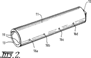
図1は、本発明に従った装置10を示している。装置10は、閉鎖円錐尖端が形成される遠位端12および開放近位端を有する中空細長部材11を含む。内側部材には複数のピン15a、15b、….15hが取り付けられる。ピン15a−15hは、それぞれの穴16a−16bを通って伸びる。穴16a−16dについては、図2にさらにはっきりと示されている。
【0024】
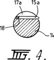
次に本発明の装置の内側部材の細部を示す図3および4を見ると、内側部材14は、中実ピンを備え、例えば機械加工により形成される横方向に伸びる複数の溝17a、17b、17c、17dを持つ。溝17a−17dは、ピンが収縮位置のときそれぞれのピン15a−15dを収める。ワイヤまたは釘18が内側部材14の長さの大部分に沿ってピン15a−15dの各々の一端を貫いて伸び、これによりピン15a−15dを内側部材14に旋回可能に取り付ける。
【0025】
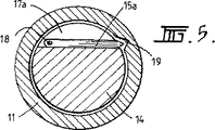
図4において最もよく示される通り、ピン15aの自由端は、内側部材14の外面を越えて伸びる。ピンの自由端が中空細長の内面に引っかからずに内側部材14を中空細長部材11に挿入できるようにするために、中空細長部材11は、ピンの自由端の先端が伸びることのできる長手方向に伸びる一本またはそれ以上の溝19(図2を参照のこと)を備えることができる。長手方向に伸びる溝19は、穴16a−16dの列と同じ線に沿って伸びることが分かるだろう。
【0026】
溝19に対する固定ピン15aの相対的位置決めについては、図5においてより明確に示される。
【0027】
図6−9は、固定ピン15aを収縮位置(図6に示される)から伸張位置(図9に示される)に移動する方法を示している。特に、内側部材14は、固定ピン15aが穴16aと整合するまで(図6に示される通り)ピン15aの先端が溝19の中を移動して、中空細長部材11の内径に沿って滑動する。図6から分かるとおり、固定ピン15aの先端は穴16aの中まで短い距離だけ伸びているが、収縮位置においては、固定ピン15aの先端は中空細長部材11の外周を越えて伸びない。
【0028】
固定ピン15aを収縮位置から動かすために、一般には内側部材14の近位端に回転力を与えることにより内側部材14を回転させる。内側部材14が回転すると、固定ピン15aの先端は穴16aの縁に捕らえられる。内側部材14の回転が続くと、固定ピン15aがワイヤ18に旋回可能に取り付けられる点20は、穴16aに向かって近づく。これにより、ピン15aは、穴16aを通って外側に向かって伸びる。図8および9に示される通り、さらに回転すると、ピンは、図9に示される完全伸張位置になるまでさらに伸びる。
【0029】
図10は、固定ピン31、32が直径方向に相対する位置に取り付けられる内側部材30の略図を示している。ピン31、32は、溝33、34にはめ込まれて、ピン31、32を内側部材30に旋回可能に接合するそれぞれの釘35、36によって保持される。
【0030】
本発明の装置を髄管に固定しやすくするために、内側部材および中空細長部材は共に、その近位端に、ツールまたは保持手段を付けることを可能にする特徴を持つまたはそのように成形されることが望ましい。これは、図11にもっとも良く示されており、この図において、内側部材30は、その近位端に、トルクまたは回転力を与えることのできるハンドル(図には示されていない)を有する相補的な形状のツール38と係合するように正方形または六角形の突出37が形成される。ツール38は、回転力を与えやすくするためにラチェット・ハンドルが取り付けられることが望ましい。
【0031】
ピンを伸ばすために回転力が内側部材に与えられるとき中空細長部材が回転するのを防ぐために、外側の中空細長部材の近位端に保持手段が形成されることが望ましい。保持手段は、安定化ツール39と係合することのできる正方形、長方形、六角形またはその他の多角形の末端を含むことができる。図12にさらに明確に示される通り、安定化ツール39は、ハンドル40および中空細長部材の近位端と係合する係合部分を含む。
【0032】
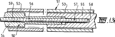
図13は、本発明のもう一つの実施態様を示しており、この実施態様においては、髄内骨固定装置は、伸縮可能の長さを持つ。特に、図13に示される装置は、内側部材50、および第一の部分52および第二の部分53を含む外側部材を含む。内側部材50も、第一の部分54および第二の部分55を含む。第一の部分54は、少なくとも小さいねじきり部分を持つボア56を含む。内側部材50の第二の部分55にもボア57があり、ボア57は、ブラインド・エンドで終結する。ねじ59が、ボア56、57にねじ込まれる。ねじが完全に挿入されると、ねじの端はブラインド・エンドにぶつかる。ねじをさらに回転させると、2つの部分54、55を押し離すことにより、内側部材50の長さを伸張することになる。ピンが髄管の周りの骨に挿入され、内側部材50の長さが伸張されると、外側部材51の長さも伸張する。
【0033】
内側部材の整合を簡単に確認できるようにするために、内側部材の近位端に何らかの印を付けることも、望ましい。
【0034】
次に、本発明のもう一つの実施態様を示す図14および15を見てみると、ピンまたは釘30は一端に球形部分31を持ち、釘の軸部32が球形部分31から伸びて尖端33まで先細となる。図14に示されるピンまたは釘30は、本発明の装置に使用される複数のピンまたは釘のうちの一本である。
【0035】
中空細長部材35(図15を参照のこと)には少なくとも一つの穴36が形成され、この少なくとも一つの穴36の直径は、ピンまたは釘30の球形部分31の直径より僅かに大きい。内側部材37は同様のサイズの穴38を含み、溝39が内側部材37の長さを横切ってこの穴を貫通する。装置にピンまたは釘30を装着するために、穴36および38は整合され、ピンまたは釘30の球形部分31が穴38に収まるまでピンまたは釘が穴から挿入される。ピンまたは釘30の尖端33は、穴36のほぼ反対側のスロットまたは孔40の中に突き出す。
【0036】
ピンまたは釘30が装着されたら、内側部材の穴38が外側管によって覆われるまで外側管を右回りに回転させる。スロット40が同時に移動して、ピンまたは釘30の尖端の遠位端に丁度接触する。ピンまたは釘30はこうして挿入の準備を完了する。
【0037】
装置が髄管に挿入されたら、ピンまたは釘30が完全に伸びるまで内側部材37を右回りの方向に回転させる。この点に関してピンまたは釘の伸張は、図6−9に示されるものと同様である。
【0038】
図14および15に示される実施態様において、ピンまたは釘30は、内側部材に接合または取り付けされない。そうではなく、ピンまたは釘は、外側管(すなわち中空細長部材)と内側部材の間の相互作用により所定の位置に保持される。この意味で、内側部材と少なくとも一本のピンまたは釘の間に物理的取り付けはなくても、内側部材は少なくとも一本のピンまたは釘を持っていることが分かるだろう。
【0039】
当業者は、本文書において説明される発明に、特に説明されるもの以外の変形および変更態様が可能であることがわかるだろう。本発明は、その精神および範囲内にあるこれら全ての変形および変更態様を包含するものとする。
【図面の簡単な説明】
【図1】 図1は、ピンが伸張位置のときの本発明に従った装置の側面断面図を示している。
【図2】 図2は、図1の装置の中空細長部材の斜視図を示している。
【図3】 図3は、ピンが収縮位置のときの図1の内側部材の上面図である。
【図4】 図4は、図3の線4−4に沿って見た断面図である。
【図5】 図5は、中空細長部材に挿入された内側部材を示す端面断面図である。
【図6】 図6から9までは、収縮位置から伸張位置に移動するピンを示す端面断面図である。
【図7】 図6から9までは、収縮位置から伸張位置に移動するピンを示す端面断面図である。
【図8】 図6から9までは、収縮位置から伸張位置に移動するピンを示す端面断面図である。
【図9】 図6から9までは、収縮位置から伸張位置に移動するピンを示す端面断面図である。
【図10】 図10は、本発明の別の実施態様の側面断面図である。
【図11】 図11は、本発明に従った装置の近位端の一部断面とした側面図である。
【図12】 図12は、図11に示される中空細長部材保持手段の略図である。
【図13】 図13は、可変長さを持つ本発明のさらに別の実施態様の断面略図である。
【図14】 図14は、本発明の別の実施態様に使用するのに適するピンまたは釘の側面図である。
【図15】 図15は、本発明の別の実施態様の端面断面図である。
Claims (17)
- 髄内骨固定装置であって、
その側壁に少なくとも一つの開口を有し骨の髄管へ挿入するようにされた中空細長部材と、
前記中空細長部材内に滑動可能に受容され得るサイズであり、少なくとも一本のピンを担持し、その外面に一つ以上の溝を有する内側部材と、を備え、
前記少なくとも一本のピンは該少なくとも一本のピンが収縮位置にある時に前記一つ以上の溝内に位置せしめられ、少なくとも一本のピンはその一方の端で前記内側部材に旋回可能に接合され、前記少なくとも一本のピンは収縮位置から該少なくとも一本のピンが前記中空細長部材の少なくとも一つの開口のそれぞれを通って伸びる伸張位置へと移動可能であり、前記少なくとも一本のピンは、該少なくとも一本のピンの自由端を前記一つ以上の開口と整合させて配置し、前記内側部材を回転させてそれによって前記ピンが前記一つ以上の開口を通って伸びるようにすることによって前記伸張位置に移動される、装置。 - 髄内骨固定装置であって、
その側壁に少なくとも一つの開口を有し骨の髄管へ挿入するようにされた中空細長部材と、
前記中空細長部材内に滑動可能に受容され得るサイズであり、少なくとも一本のピンを担持している内側部材と、を備え、
前記少なくとも一本のピンは収縮位置から該少なくとも一本のピンが前記中空細長部材の少なくとも一つの開口のそれぞれを通って伸びる伸張位置へと移動可能であり、前記少なくとも一本のピンはその一方の端に拡大部を有し、該拡大部は前記内側部材に形成されるそれぞれの穴または窪みに収まり、前記少なくとも一本のピンは収縮位置にある時に前記内側部材に形成されるそれぞれの溝に沿って伸び、前記一本以上のピンは前記中空細長部材の内壁によって所定の位置に保持されると共に、前記一本以上のピンはその自由端を前記中空細長部材の前記少なくとも一つの開口と整合させ前記内側部材を回転させることにより伸ばされる、装置。 - 前記少なくとも一本のピンの自由端が前記内側部材の表面を僅かに越えて伸びる、請求項1または2に記載の装置。
- 前記一つ以上の溝が概ね横方向に伸びる溝である、請求項1から3の何れか一項に記載の装置。
- 前記少なくとも一本のピンの自由端が収縮位置にある時に前記開口のそれぞれの中へ伸びる、請求項3に記載の装置。
- 前記中空細長部材の内壁に溝が設けられ、該溝は前記少なくとも一本のピンの自由端を受容しそれによって前記中空細長部材内への前記内側部材の長手方向の挿入を可能とする、請求項3に記載の装置。
- 前記内側部材の回転により、前記少なくとも一本のピンの旋回可能に取り付けられた端とそれぞれの開口との距離が減少し、それによって前記少なくとも一本のピンがそれぞれの開口を通って外側へ移動する、請求項1に記載の装置。
- 前記内側部材の回転により、前記少なくとも一本のピンの拡大された端とそれぞれの開口との距離が減少し、それによって前記少なくとも一本のピンがそれぞれの開口を通って外側へ移動する、請求項2に記載の装置。
- 前記中空細長部材を髄管に挿入しやすくするために、前記中空細長部材がその遠位端に尖端または閉鎖端を有する、請求項1または2に記載の装置。
- 前記中空細長部材の遠位端が円錐形尖端を備える、請求項9に記載の装置。
- 前記内側部材を前記中空細長部材にぴったりと合うが密着しすぎないサイズとすることにより、前記中空細長部材内で前記内側部材が容易に動けるようにしながら、前記内側部材と前記中空細長部材の間にゆるみが生じないようにする、請求項1から10の何れか一項に記載の装置。
- 前記内側部材および前記中空細長部材が共に、その長さの大部分において円筒形である、請求項1から11の何れか一項に記載の装置。
- 前記内側部材が複数のピンを有する、請求項1から12の何れか一項に記載の装置。
- 前記内側部材の近位端が、ハンドルまたはトルクを与える手段と係合するための係合面を備える、請求項1から13の何れか一項に記載の装置。
- 前記中空細長部材が、前記中空細長部材を所定の位置に保持しその回転を防止するための保持面を備える、請求項1から14の何れか一項に記載の装置。
- 前記中空細長部材および前記内側部材が固定長さを有する、請求項1から15の何れか一項に記載の装置。
- 前記中空細長部材および前記内側部材が調節可能な長さを有する、請求項1から15の何れか一項に記載の装置。
Applications Claiming Priority (5)
| Application Number | Priority Date | Filing Date | Title |
|---|---|---|---|
| AU0336 | 1988-09-09 | ||
| AUPP6847A AUPP684798A0 (en) | 1998-10-30 | 1998-10-30 | Intra-medullary bone fixation device |
| AUPQ0336A AUPQ033699A0 (en) | 1999-05-13 | 1999-05-13 | Apparatus for fixing to a structure or the like |
| AU6847 | 1999-05-13 | ||
| PCT/AU1999/000937 WO2000025690A1 (en) | 1998-10-30 | 1999-10-28 | Fixation device |
Publications (3)
| Publication Number | Publication Date |
|---|---|
| JP2002528219A JP2002528219A (ja) | 2002-09-03 |
| JP2002528219A5 JP2002528219A5 (ja) | 2006-12-28 |
| JP4128748B2 true JP4128748B2 (ja) | 2008-07-30 |
Family
ID=25645908
Family Applications (1)
| Application Number | Title | Priority Date | Filing Date |
|---|---|---|---|
| JP2000579139A Expired - Fee Related JP4128748B2 (ja) | 1998-10-30 | 1999-10-28 | 髄内骨固定装置 |
Country Status (7)
| Country | Link |
|---|---|
| US (1) | US6447513B1 (ja) |
| EP (1) | EP1124497B1 (ja) |
| JP (1) | JP4128748B2 (ja) |
| AT (1) | ATE322868T1 (ja) |
| CA (1) | CA2348441C (ja) |
| DE (1) | DE69930867T2 (ja) |
| WO (1) | WO2000025690A1 (ja) |
Families Citing this family (91)
| Publication number | Priority date | Publication date | Assignee | Title |
|---|---|---|---|---|
| US7959652B2 (en) | 2005-04-18 | 2011-06-14 | Kyphon Sarl | Interspinous process implant having deployable wings and method of implantation |
| US20080086212A1 (en) | 1997-01-02 | 2008-04-10 | St. Francis Medical Technologies, Inc. | Spine distraction implant |
| US6068630A (en) | 1997-01-02 | 2000-05-30 | St. Francis Medical Technologies, Inc. | Spine distraction implant |
| US20080039859A1 (en) | 1997-01-02 | 2008-02-14 | Zucherman James F | Spine distraction implant and method |
| US7306628B2 (en) | 2002-10-29 | 2007-12-11 | St. Francis Medical Technologies | Interspinous process apparatus and method with a selectably expandable spacer |
| US7201751B2 (en) | 1997-01-02 | 2007-04-10 | St. Francis Medical Technologies, Inc. | Supplemental spine fixation device |
| JP4125234B2 (ja) * | 2001-11-01 | 2008-07-30 | スパイン・ウェイブ・インコーポレーテッド | 椎間板間の終板の前処理のための装置及び方法 |
| FR2844179B1 (fr) | 2002-09-10 | 2004-12-03 | Jean Taylor | Ensemble de soutien vertebral posterieur |
| US8147548B2 (en) | 2005-03-21 | 2012-04-03 | Kyphon Sarl | Interspinous process implant having a thread-shaped wing and method of implantation |
| US8048117B2 (en) | 2003-05-22 | 2011-11-01 | Kyphon Sarl | Interspinous process implant and method of implantation |
| US8070778B2 (en) | 2003-05-22 | 2011-12-06 | Kyphon Sarl | Interspinous process implant with slide-in distraction piece and method of implantation |
| US7749252B2 (en) | 2005-03-21 | 2010-07-06 | Kyphon Sarl | Interspinous process implant having deployable wing and method of implantation |
| US20080021468A1 (en) | 2002-10-29 | 2008-01-24 | Zucherman James F | Interspinous process implants and methods of use |
| WO2005058174A1 (de) * | 2003-12-19 | 2005-06-30 | Synthes Ag Chur | Marknagel |
| EP1708632A1 (en) * | 2004-01-16 | 2006-10-11 | Expanding Orthopedics, Inc. | Bone fracture treatment devices |
| DE102004009429A1 (de) | 2004-02-24 | 2005-09-22 | Biedermann Motech Gmbh | Knochenverankerungselement |
| JP4991565B2 (ja) * | 2005-01-31 | 2012-08-01 | ロス グリッグス,イアン | 改良された髄内式骨組織デバイス |
| AU2006208431B2 (en) * | 2005-01-31 | 2010-07-22 | Ian Ross Griggs | Improved intramedullary bone device |
| US20070276493A1 (en) * | 2005-02-17 | 2007-11-29 | Malandain Hugues F | Percutaneous spinal implants and methods |
| US8096994B2 (en) | 2005-02-17 | 2012-01-17 | Kyphon Sarl | Percutaneous spinal implants and methods |
| US8057513B2 (en) | 2005-02-17 | 2011-11-15 | Kyphon Sarl | Percutaneous spinal implants and methods |
| US8038698B2 (en) | 2005-02-17 | 2011-10-18 | Kphon Sarl | Percutaneous spinal implants and methods |
| US8100943B2 (en) | 2005-02-17 | 2012-01-24 | Kyphon Sarl | Percutaneous spinal implants and methods |
| US8029567B2 (en) | 2005-02-17 | 2011-10-04 | Kyphon Sarl | Percutaneous spinal implants and methods |
| US8007521B2 (en) | 2005-02-17 | 2011-08-30 | Kyphon Sarl | Percutaneous spinal implants and methods |
| US7988709B2 (en) | 2005-02-17 | 2011-08-02 | Kyphon Sarl | Percutaneous spinal implants and methods |
| US8034080B2 (en) | 2005-02-17 | 2011-10-11 | Kyphon Sarl | Percutaneous spinal implants and methods |
| US8157841B2 (en) | 2005-02-17 | 2012-04-17 | Kyphon Sarl | Percutaneous spinal implants and methods |
| US7998174B2 (en) * | 2005-02-17 | 2011-08-16 | Kyphon Sarl | Percutaneous spinal implants and methods |
| US8097018B2 (en) | 2005-02-17 | 2012-01-17 | Kyphon Sarl | Percutaneous spinal implants and methods |
| US8034079B2 (en) | 2005-04-12 | 2011-10-11 | Warsaw Orthopedic, Inc. | Implants and methods for posterior dynamic stabilization of a spinal motion segment |
| US7727233B2 (en) | 2005-04-29 | 2010-06-01 | Warsaw Orthopedic, Inc. | Spinous process stabilization devices and methods |
| CA2608693A1 (en) | 2005-05-18 | 2006-11-23 | Sonoma Orthopedic Products, Inc. | Minimally invasive actuable bone fixation devices, systems and methods of use |
| US8961516B2 (en) | 2005-05-18 | 2015-02-24 | Sonoma Orthopedic Products, Inc. | Straight intramedullary fracture fixation devices and methods |
| US9060820B2 (en) | 2005-05-18 | 2015-06-23 | Sonoma Orthopedic Products, Inc. | Segmented intramedullary fracture fixation devices and methods |
| FR2887434B1 (fr) | 2005-06-28 | 2008-03-28 | Jean Taylor | Materiel de traitement chirurgical de deux vertebres |
| KR101145415B1 (ko) * | 2005-07-08 | 2012-05-15 | 비이더만 모테크 게엠베하 & 코. 카게 | 뼈 고정 요소 |
| DE602005011124D1 (de) * | 2005-08-05 | 2009-01-02 | Biedermann Motech Gmbh | Knochenverankerungselement |
| US8083795B2 (en) | 2006-01-18 | 2011-12-27 | Warsaw Orthopedic, Inc. | Intervertebral prosthetic device for spinal stabilization and method of manufacturing same |
| DE602006002105D1 (de) * | 2006-02-23 | 2008-09-18 | Biedermann Motech Gmbh | Knochenverankerungsvorrichtung |
| US8262698B2 (en) | 2006-03-16 | 2012-09-11 | Warsaw Orthopedic, Inc. | Expandable device for insertion between anatomical structures and a procedure utilizing same |
| US8118844B2 (en) | 2006-04-24 | 2012-02-21 | Warsaw Orthopedic, Inc. | Expandable device for insertion between anatomical structures and a procedure utilizing same |
| US8048118B2 (en) | 2006-04-28 | 2011-11-01 | Warsaw Orthopedic, Inc. | Adjustable interspinous process brace |
| US8048119B2 (en) | 2006-07-20 | 2011-11-01 | Warsaw Orthopedic, Inc. | Apparatus for insertion between anatomical structures and a procedure utilizing same |
| US20080086115A1 (en) | 2006-09-07 | 2008-04-10 | Warsaw Orthopedic, Inc. | Intercostal spacer device and method for use in correcting a spinal deformity |
| DE102006046330A1 (de) * | 2006-09-28 | 2008-04-03 | Bayer Materialscience Ag | Polycarbonate und Copolycarbonate mit verbesserter Metallhaftung |
| US8361130B2 (en) * | 2006-10-06 | 2013-01-29 | Depuy Spine, Inc. | Bone screw fixation |
| US8097019B2 (en) | 2006-10-24 | 2012-01-17 | Kyphon Sarl | Systems and methods for in situ assembly of an interspinous process distraction implant |
| FR2908035B1 (fr) | 2006-11-08 | 2009-05-01 | Jean Taylor | Implant interepineux |
| US7879104B2 (en) | 2006-11-15 | 2011-02-01 | Warsaw Orthopedic, Inc. | Spinal implant system |
| EP2094177A2 (en) | 2006-11-22 | 2009-09-02 | Sonoma Orthopedic Products, Inc. | Fracture fixation device, tools and methods |
| US7955392B2 (en) | 2006-12-14 | 2011-06-07 | Warsaw Orthopedic, Inc. | Interspinous process devices and methods |
| US8333787B2 (en) | 2007-12-31 | 2012-12-18 | St. Jude Medical Puerto Rico Llc | Vascular closure device having a flowable sealing material |
| US8568445B2 (en) | 2007-08-21 | 2013-10-29 | St. Jude Medical Puerto Rico Llc | Extra-vascular sealing device and method |
| US8840640B2 (en) * | 2007-12-31 | 2014-09-23 | St. Jude Medical Puerto Rico Llc | Vascular closure device having an improved plug |
| US8282675B2 (en) | 2008-01-25 | 2012-10-09 | Depuy Spine, Inc. | Anti-backout mechanism |
| US20090198338A1 (en) | 2008-02-04 | 2009-08-06 | Phan Christopher U | Medical implants and methods |
| US8114136B2 (en) | 2008-03-18 | 2012-02-14 | Warsaw Orthopedic, Inc. | Implants and methods for inter-spinous process dynamic stabilization of a spinal motion segment |
| US20090255549A1 (en) * | 2008-04-14 | 2009-10-15 | Eldrege Smith | Hair Roller |
| WO2009152273A1 (en) | 2008-06-10 | 2009-12-17 | Sonoma Orthopedic Products, Inc. | Fracture fixation device, tools and methods |
| CA2738478A1 (en) | 2008-09-26 | 2010-04-01 | Sonoma Orthopedic Products, Inc. | Bone fixation device, tools and methods |
| US8114131B2 (en) | 2008-11-05 | 2012-02-14 | Kyphon Sarl | Extension limiting devices and methods of use for the spine |
| US8915919B2 (en) * | 2009-04-02 | 2014-12-23 | Orthorifling Systems, Llc | Bone rifling system and method of preparing a bone using such system |
| US8372117B2 (en) | 2009-06-05 | 2013-02-12 | Kyphon Sarl | Multi-level interspinous implants and methods of use |
| EP2437678A4 (en) * | 2009-06-05 | 2015-10-28 | Univ Sydney | SCREW |
| US8157842B2 (en) | 2009-06-12 | 2012-04-17 | Kyphon Sarl | Interspinous implant and methods of use |
| US9693837B2 (en) * | 2009-08-06 | 2017-07-04 | Sue S. Lee | Dental implant |
| US10265435B2 (en) | 2009-08-27 | 2019-04-23 | Silver Bullet Therapeutics, Inc. | Bone implant and systems and coatings for the controllable release of antimicrobial metal ions |
| US9821094B2 (en) | 2014-06-11 | 2017-11-21 | Silver Bullet Therapeutics, Inc. | Coatings for the controllable release of antimicrobial metal ions |
| WO2011031548A2 (en) | 2009-08-27 | 2011-03-17 | Silver Bullet Therapeutics, Inc. | Bone implants for the treatment of infection |
| KR101058795B1 (ko) * | 2009-08-31 | 2011-08-23 | 김민석 | 척추 고정용 나사 |
| US8771317B2 (en) | 2009-10-28 | 2014-07-08 | Warsaw Orthopedic, Inc. | Interspinous process implant and method of implantation |
| US8114132B2 (en) | 2010-01-13 | 2012-02-14 | Kyphon Sarl | Dynamic interspinous process device |
| US8317831B2 (en) | 2010-01-13 | 2012-11-27 | Kyphon Sarl | Interspinous process spacer diagnostic balloon catheter and methods of use |
| US8147526B2 (en) | 2010-02-26 | 2012-04-03 | Kyphon Sarl | Interspinous process spacer diagnostic parallel balloon catheter and methods of use |
| US8617160B2 (en) | 2010-03-09 | 2013-12-31 | Torjo Medical Solutions, Inc. | Dynamic intramedullary hardware |
| US8814908B2 (en) | 2010-07-26 | 2014-08-26 | Warsaw Orthopedic, Inc. | Injectable flexible interspinous process device system |
| WO2012064402A1 (en) | 2010-11-12 | 2012-05-18 | Silver Bullet Therapeutics, Inc. | Bone implant and systems that controllably releases silver |
| US8591548B2 (en) | 2011-03-31 | 2013-11-26 | Warsaw Orthopedic, Inc. | Spinous process fusion plate assembly |
| US8591549B2 (en) | 2011-04-08 | 2013-11-26 | Warsaw Orthopedic, Inc. | Variable durometer lumbar-sacral implant |
| US8652136B2 (en) * | 2011-08-15 | 2014-02-18 | Zimmer, Gmbh | Femoral fracture fixation device |
| WO2015061556A2 (en) * | 2013-10-23 | 2015-04-30 | Extremity Medical Llc | Devices and methods for bone fixation using an intramedullary fixation implant |
| US9770278B2 (en) | 2014-01-17 | 2017-09-26 | Arthrex, Inc. | Dual tip guide wire |
| US9452242B2 (en) | 2014-06-11 | 2016-09-27 | Silver Bullet Therapeutics, Inc. | Enhancement of antimicrobial silver, silver coatings, or silver platings |
| US9814499B2 (en) | 2014-09-30 | 2017-11-14 | Arthrex, Inc. | Intramedullary fracture fixation devices and methods |
| CN104287819B (zh) * | 2014-10-09 | 2016-06-29 | 中国人民解放军第四军医大学 | 一种医用可伸缩双螺纹、抗拔出的椎弓根螺钉组件 |
| US9827025B2 (en) | 2015-11-20 | 2017-11-28 | Globus Medical, Inc. | Expandable intramedullary systems and methods of using the same |
| US9974581B2 (en) | 2015-11-20 | 2018-05-22 | Globus Medical, Inc. | Expandable intramedullary systems and methods of using the same |
| US10092333B2 (en) | 2015-11-20 | 2018-10-09 | Globus Medical, Inc. | Expandable intramedullary systems and methods of using the same |
| CN105736540B (zh) * | 2016-05-09 | 2018-03-23 | 广东工业大学 | 一种固定装置 |
| TWI649062B (zh) * | 2018-04-26 | 2019-02-01 | 台灣微創醫療器材股份有限公司 | 脊椎擴孔裝置 |
Family Cites Families (15)
| Publication number | Priority date | Publication date | Assignee | Title |
|---|---|---|---|---|
| US4237875A (en) * | 1979-02-23 | 1980-12-09 | Towmotor Corporation | Dynamic intramedullary compression nailing |
| DE2944050B1 (de) * | 1979-10-31 | 1981-04-30 | Icomag Trust Reg., Vaduz | Lockenwickler |
| US4335732A (en) * | 1981-01-26 | 1982-06-22 | Salvatore Megna | Hair curling iron |
| DE3204469A1 (de) | 1982-02-09 | 1983-09-01 | WIK Elektro-Hausgeräte-Vertriebsgesellschaft mbH & Co Produktionskommanditgesellschaft, 4300 Essen | Frisiergeraet zum stylen, aufwickeln und trocknen von haaren |
| US4473086A (en) * | 1982-02-19 | 1984-09-25 | Save-Way Industries, Inc. | Hair curling device having retractable teeth and locking means therefor |
| US4453539A (en) * | 1982-03-01 | 1984-06-12 | The University Of Toledo | Expandable intramedullary nail for the fixation of bone fractures |
| DE3318751A1 (de) * | 1983-05-24 | 1984-12-06 | Peter Dipl.-Ing. 8374 Viechtach Bertsche | Kraftuebertragende holzverbindung |
| US5057103A (en) * | 1990-05-01 | 1991-10-15 | Davis Emsley A | Compressive intramedullary nail |
| EP0636346A1 (en) * | 1993-07-23 | 1995-02-01 | Massimo Santangelo | Device for preventive support of the femur |
| IT1265965B1 (it) * | 1994-05-20 | 1996-12-16 | Francesco Saverio Santori | Dispositivo endomillare per la chiodatura di ossa lunghe. |
| US5702215A (en) * | 1995-06-05 | 1997-12-30 | Li Medical Technologies, Inc. | Retractable fixation device |
| IT1287271B1 (it) * | 1996-04-05 | 1998-08-04 | Antonio Chemello | Chiodo endomidollare per l'osteosintesi delle fratture delle ossa lunghe |
| AU3021897A (en) | 1996-06-18 | 1998-01-07 | Marc D. Grynpas | Bone prosthesis fixation device and methods of using same |
| IT1284694B1 (it) * | 1996-07-23 | 1998-05-21 | Francesco Saverio Santori | Dispositivo endomidollare per la chiodatura di ossa. |
| GB9709509D0 (en) | 1997-05-12 | 1997-07-02 | Univ Aberdeen | Retractable intramedullary nail |
-
1999
- 1999-10-28 US US09/830,768 patent/US6447513B1/en not_active Expired - Lifetime
- 1999-10-28 EP EP99955600A patent/EP1124497B1/en not_active Expired - Lifetime
- 1999-10-28 JP JP2000579139A patent/JP4128748B2/ja not_active Expired - Fee Related
- 1999-10-28 DE DE69930867T patent/DE69930867T2/de not_active Expired - Lifetime
- 1999-10-28 CA CA002348441A patent/CA2348441C/en not_active Expired - Fee Related
- 1999-10-28 WO PCT/AU1999/000937 patent/WO2000025690A1/en active IP Right Grant
- 1999-10-28 AT AT99955600T patent/ATE322868T1/de not_active IP Right Cessation
Also Published As
| Publication number | Publication date |
|---|---|
| EP1124497A4 (en) | 2003-02-05 |
| US6447513B1 (en) | 2002-09-10 |
| EP1124497A1 (en) | 2001-08-22 |
| CA2348441A1 (en) | 2000-05-11 |
| ATE322868T1 (de) | 2006-04-15 |
| EP1124497B1 (en) | 2006-04-12 |
| CA2348441C (en) | 2008-01-22 |
| JP2002528219A (ja) | 2002-09-03 |
| WO2000025690A1 (en) | 2000-05-11 |
| DE69930867D1 (de) | 2006-05-24 |
| DE69930867T2 (de) | 2006-11-23 |
Similar Documents
| Publication | Publication Date | Title |
|---|---|---|
| JP4128748B2 (ja) | 髄内骨固定装置 | |
| JP4902539B2 (ja) | デュアル・ロッド・クロスコネクタおよび挿入用工具 | |
| US8623020B2 (en) | Vertebral staples and insertion tools | |
| US6527773B1 (en) | Cervical dowel and insertion tool | |
| US5098433A (en) | Winged compression bolt orthopedic fastener | |
| US20080119854A1 (en) | Bone fixture apparatus and jig | |
| US8034054B2 (en) | Intramedullary bone device | |
| US20050010223A1 (en) | Intramedullary nail system and method for fixation of a fractured bone | |
| WO2001017465A1 (en) | Temporary spine fixation device and method | |
| CA2444914A1 (en) | Fermoral nail intamedullary system | |
| JP2008536563A (ja) | インプラント留め具用抜出し防止機構 | |
| SK283792B6 (sk) | Distrakčné zariadenie obsluhované pacientom | |
| HU220351B (hu) | Fúróvezető készülék és eljárás az emberi combcsontszár combnyakán hosszanti furat kifúrásához | |
| WO2001089395A2 (en) | Radiolucent aiming guide | |
| US5152766A (en) | Femoral wire guide instrument | |
| JPH11137566A (ja) | 髄内釘 | |
| CN108135703B (zh) | 用于髋臼杯紧固件的钻孔引导件 | |
| AU755111B2 (en) | Fixation device | |
| US20220096250A1 (en) | Osseointegration system | |
| AU2006208431B2 (en) | Improved intramedullary bone device | |
| HU191355B (en) | Stabilization bone nail and placing and pointing device for grafting the bone nail |
Legal Events
| Date | Code | Title | Description |
|---|---|---|---|
| A521 | Request for written amendment filed |
Free format text: JAPANESE INTERMEDIATE CODE: A523 Effective date: 20061020 |
|
| A621 | Written request for application examination |
Free format text: JAPANESE INTERMEDIATE CODE: A621 Effective date: 20061020 |
|
| A131 | Notification of reasons for refusal |
Free format text: JAPANESE INTERMEDIATE CODE: A131 Effective date: 20071016 |
|
| A521 | Request for written amendment filed |
Free format text: JAPANESE INTERMEDIATE CODE: A523 Effective date: 20080116 |
|
| TRDD | Decision of grant or rejection written | ||
| A01 | Written decision to grant a patent or to grant a registration (utility model) |
Free format text: JAPANESE INTERMEDIATE CODE: A01 Effective date: 20080415 |
|
| A01 | Written decision to grant a patent or to grant a registration (utility model) |
Free format text: JAPANESE INTERMEDIATE CODE: A01 |
|
| A61 | First payment of annual fees (during grant procedure) |
Free format text: JAPANESE INTERMEDIATE CODE: A61 Effective date: 20080515 |
|
| FPAY | Renewal fee payment (event date is renewal date of database) |
Free format text: PAYMENT UNTIL: 20110523 Year of fee payment: 3 |
|
| R150 | Certificate of patent or registration of utility model |
Free format text: JAPANESE INTERMEDIATE CODE: R150 |
|
| FPAY | Renewal fee payment (event date is renewal date of database) |
Free format text: PAYMENT UNTIL: 20120523 Year of fee payment: 4 |
|
| FPAY | Renewal fee payment (event date is renewal date of database) |
Free format text: PAYMENT UNTIL: 20130523 Year of fee payment: 5 |
|
| R250 | Receipt of annual fees |
Free format text: JAPANESE INTERMEDIATE CODE: R250 |
|
| R250 | Receipt of annual fees |
Free format text: JAPANESE INTERMEDIATE CODE: R250 |
|
| R250 | Receipt of annual fees |
Free format text: JAPANESE INTERMEDIATE CODE: R250 |
|
| LAPS | Cancellation because of no payment of annual fees |