JP4117414B2 - High-rise building - Google Patents
High-rise building Download PDFInfo
- Publication number
- JP4117414B2 JP4117414B2 JP18534798A JP18534798A JP4117414B2 JP 4117414 B2 JP4117414 B2 JP 4117414B2 JP 18534798 A JP18534798 A JP 18534798A JP 18534798 A JP18534798 A JP 18534798A JP 4117414 B2 JP4117414 B2 JP 4117414B2
- Authority
- JP
- Japan
- Prior art keywords
- evacuation
- building
- balcony
- corridor
- smoke
- Prior art date
- Legal status (The legal status is an assumption and is not a legal conclusion. Google has not performed a legal analysis and makes no representation as to the accuracy of the status listed.)
- Expired - Fee Related
Links
Images


Description
【0001】
【発明の属する技術分野】
本発明は、少なくとも上部に複数の住戸が配置され、かつ当該住戸における火災時の避難および消火活動を防護するための避難システムを備えた高層建物に関するものである。
【0002】
【従来の技術】
一般に、多数の住戸を有する共同住宅においては、これら住戸の共用廊下に、非常時の避難用として別途共用の避難階段を設けるとともに、これに加えて、例えば火災時のように、煙によって上記共用廊下を通じて避難階段への退避路が確保できない時のために、各住戸に外部バルコニーを設置することにより、合計2方向の避難路を設けて安全性を確保している。
【0003】
【発明が解決しようとする課題】
ところで、このような構成からなる従来の共同住宅にあっては、特に高層になった場合に、同様に外部バルコニーを設置すると、当該バルコニーからの落下物によって地上における危険性が増大したり、あるいは外部の風圧によって居住性に障害を与えるといった問題が生じる。
加えて、特に建物の有効利用を図るために、下部に事務所用スペースを配置して、高層部にのみ共同住宅区画を配置した高層建物においては、上記外部バルコニーによって建物全体としての外観の統一性が損なわれて美観に劣るという問題点もある。
【0004】
そこで、上記住戸に外部バルコニーを設けない設計も考えられるが、従来の避難階段に加えて別途第2の避難路を確保することが難しいうえに、外部バルコニーを廃止した結果、建物における気密性が大幅に増加し、却って火災時に共用廊下への煙等の侵入や滞留が発生し易くなって、充分な安全性を確保することが難しくなってしまうという問題点があった。
【0005】
本発明は、このような従来の高層建物が有する問題点を有効に解消すべくなされたもので、各住戸に外部バルコニーを設けることなく、かつ火災時等に複数の方向への避難路を確保することができるとともに、避難経路への煙等の侵入を確実に防止することができ、よって円滑な避難および消火活動を確保することができる高層建物を提供することを目的とするものである。
【0006】
【課題を解決するための手段】
請求項1に記載の本発明に係る高層建物は、住戸に外部バルコニーを設けない設計の高層建物において、前記住戸が配設された階における当該建物の中央部に、透明ガラスで仕切られたボイドを形成し、このボイドに沿って廊下を配置するとともに、この廊下に面し、かつ避難階段に通じる附室を設け、前記建物の外周四面に、屋外に面するとともに前記廊下に通じる避難バルコニーをそれぞれ設置し、さらに前記廊下の周囲に、該廊下に通じる複数の出入口を有し、かつ外部バルコニーを有しない複数の住戸を前記建物の外周に沿って配置するとともに、前記住戸に排煙設備を設け、前記附室に給気設備を設け、かつ前記廊下と前記避難バルコニーとの間に、前記給気設備による給気量と前記排煙設備による排煙量との差に基づく余剰分の給気または煙を排気する排気設備を設けた高層建物であって、前記建物外周部の住戸間に、前記避難バルコニーをそれぞれ設置するとともに、前記廊下は、前記ボイドに沿う周回部と、当該周回部から四方向に延出する部分とを有し、その延出する部分が防火扉を介して各避難バルコニーに通じ、各避難バルコニーが下階の避難待機スペースに通じる構成としたことを特徴とするものである。
【0007】
ここで、請求項2に記載の発明は、請求項1に記載の建物は、下部に事務所用スペースが配置され、上部に前記複数の住戸が配設されているとともに、これら上下部間に、避難階段および避難バルコニーに通じる共用の避難待機スペースが設けられていることを特徴とするものである。
また、請求項3に記載の発明は、請求項1に記載の排気設備は、風圧の高い外周面から建物内へ外気風が侵入することを防止する逆流防止機能付きの差圧ダンパーを備えることを特徴とするものである。
【0008】
本発明に係る高層建物によれば、各住戸に外部バルコニーが設けられていないため、高層であっても、当該外部バルコニーからの落下物によって地上における危険性が増大したり、あるいは外部の風圧によって居住性に障害を与えるというおそれが無い。
また、避難階段と建物外周に設けた避難バルコニーとの2方向の避難路が確保されるているので、火災時には、廊下を通じて避難階段へと避難することができ、万一避難階段の使用が不可能となった場合には、避難バルコニーから脱出することができる。
【0009】
この際に、上記住戸に排煙設備を設け、附室に給気設備を設けるとともに、廊下と避難バルコニーとの間に、給気設備による給気量と排煙設備による排煙量との差に基づく余剰分の給気または煙を排気する排気設備を設けているので、住戸における火災発生時に、排煙設備を作動させて当該住戸内の煙を外部へ排出し、この住戸内を負圧状態に保持するとともに、これと並行して給気設備を作動させ、外の空気を附室を介して廊下へ給気することにより、附室および廊下を加圧状態に保持し、さらに給気設備によって給気される余剰の空気を、上記廊下から排気設備を介して建物の外に排気することができる。
【0010】
この結果、常に廊下から住戸内へ向かう空気の流れを形成することができ、しかも附室と廊下との間に適度の差圧が確保されるために、廊下への煙の侵入および火災の拡大を防止することができ、よって廊下を通じた避難階段または避難バルコニーを利用した避難および消火活動を円滑に行うことができる。
また、廊下を通じた避難を行うにあたっては、中央のボイドと廊下とが透明ガラスによって仕切られているため、廊下の採光性が増し、よって当該避難の安全性を高めることができる。
【0011】
なお、火災が発生した住戸において排煙を行うに際し、火源へ加圧給気によって新鮮な空気が直接供給されることを防いで、火源強度の増大を未然に防ぐ観点から、上記住戸における排煙設備の排煙口は、極力出入口となる扉の付近に設置することが好ましい。
【0012】
また、各住戸が外部バルコニーを有していない結果、特に請求項2に記載の発明のように、下部に事務所用スペースが配置され、上部に上記複数の住戸が配設されている高層建物に適用した場合においても、高層部の共同住宅区画における外観を下部の事務所用スペースの外観とほぼ同一にすることができ、よって建物全体としての外観の統一性を図ることが可能になる。
【0013】
加えて、これら上下部間に、避難階段および避難バルコニーに通じる共用の避難待機スペースを設けているので、これによって避難時における混雑を緩和することができ、また消火・救助活動においては、上記避難待機スペースを有効な活動スペースとして利用することができるとともに、さらにこの避難待機スペースから避難バルコニーを介して上階に登り、各階に侵入することにより、迅速な消火・救助活動を行うことができる。
【0014】
【発明の実施の形態】
以下、図1〜図5に基づいて、本発明に係る高層建物の一実施形態について説明する。
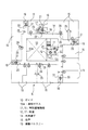
図1および図2に示すように、この高層建物1は、地上部のロビー2の上階から中層階までに事務所用スペース3が配置され、これより上部の高層階に複数の住戸15が配設された共同住宅スペース5が配置されている。そして、これら事務所用スペース3と共同住宅スペース5との間に、機械室6および避難待機スペース7が設けられている。また、屋上にも、非常時に利用可能な避難待機スペース8が確保されている。
【0015】
ここで、上記共同住宅スペース5は、図1に示すように、中央部に透明ガラス10aによって仕切られたボイド10が形成され、このボイド10に隣接して、特別避難階段11に通じる附室兼用乗降ロビー(附室)12およびこの附室兼用乗降ロビー12から乗降する非常用エレベータ13が配置されている。
【0016】
そして、これらボイド10等を周回するように共用廊下14が設けられており、この共用廊下14の外周側に複数(図では11戸)の上記住戸15が建物の外周に沿って配置されている。また、隣接する住戸15間の一個所にも、同様の特別避難階段16およびこれに通じる附室兼用乗降ロビー(附室)17並びに非常用エレベータ18が配設されている。ここで、上記特別避難階段11,16は、それぞれこの高層建物1の屋上から地下まで連続して設けられている。
【0017】
また、共同住宅スペース5における外周四面には、それぞれ避難バルコニー19が設けられており、周回部から四方向に延出した上記共用廊下14の外周側端部が、防火扉20を介して各避難バルコニー19に通じている。そして、これら避難バルコニー19に沿って下階に降りることにより、上述した避難待機スペース7に通じるようになっている。
さらに、図1および図4に示すように、附室兼用乗降ロビー12、17と特別避難階段11,16との間に、常時は閉状態となる防火扉21が設けられている。また、附室兼用乗降ロビー12,17と共用廊下14との間には、常時は開状態であって火災時にこれらの間の遮断する防火扉22が設けられており、この防火扉22付近には、附室兼用乗降ロビー12と共用廊下14とを連通させるバイパスダンパー23が設けられている。
【0018】
このバイパスダンパー23は、共用廊下14の床付近に設置されるとともに、共用廊下14側から附室兼用乗降ロビー12側へ向う空気の流れを阻止する逆流防止装置が設けられている。これにより、加圧給気を共用廊下14の下部に供給して、共用廊下14に煙が侵入した際に、上部の煙層の乱れを防止して、下部の空気層の清浄度を保つようになっている。
【0019】
さらに、附室兼用乗降ロビー12,17には、給気設備24が設けられている。この給気設備24は、図示されない加圧給気ファンによって建物外部の新鮮な空気が供給されるようになっており、上記加圧給気ファンには回転数制御による圧力制御装置が設けられている。
他方、各々の住戸15には、共用廊下14に通じる2つの扉25が設けられ、天井部の一方の扉25の近傍には排気口26が設けられ、排煙ダンパー27を介して排煙設備28に接続されている。
【0020】
この排煙設備28は、各住戸15に設置された煙感知器からの検出信号によって作動するようになっており、さらにこの排煙設備28の作動と給気設備24の作動とが互いに連動するように設定されている。
また、共用廊下14と避難バルコニー19との間には、逆流防止装置付きの差圧ダンパー29および外壁ダンパー30を備えた排気設備31が設けられている。そして、この外壁ダンパー30は、給気設備24の給気ファンの作動信号によって開作動されるようになっている。
【0021】
次に、図1〜図5に基づいて、上記構成からなる高層建物の作用について説明する。
共同住宅スペース5のいずれかの階の住戸15において火災が発生した場合、図4に示すように、この火災が当該住戸15の煙感知器によって検出されるとともに、その火災検出信号が制御手段へ送出され、この制御手段から排煙設備28へ駆動信号が送出されて、排煙ダンパー27が開放されることにより排煙操作が開始される。
【0022】
これと同時に、上記制御手段からの信号により給気設備24が作動することにより、附室兼用乗降ロビー12,17への給気操作が開始される。なお、以降この給気操作は、圧力制御装置によって加圧給気ファンが回転数制御されることにより、附室兼用乗降ロビー12,17が常に一定の正圧に保持される。
さらに、給気設備24における加圧給気ファンの作動信号によって、外壁ダンパー30が開く。
【0023】
この際、火災の初期段階においては避難のために、防火扉22や扉25は開放されており、この状態において、住戸15内における排煙操作が継続されることにより負圧状態に保持され、また附室兼用乗降ロビー12,17の給気操作の継続によってこれら附室兼用乗降ロビー12,17が加圧状態に保持される。また、この附室兼用乗降ロビー12,17と連続する共用廊下14も同様に加圧状態となる。そして、給気設備24による給気量と排煙設備28による排煙量との差による余剰分の給気が、差圧ダンパー29から外壁ダンパー30を介して外方へ排気される。
【0024】
この結果、この建物内における空気の流れは、図4に矢印で示すように、附室兼用乗降ロビー12,17から共用廊下14を経て住戸15へ至るとともに、余剰分が共用廊下14から避難バルコニー19近傍に設けられている排気設備31への流れとなる。そして、排気設備31により、附室兼用乗降ロビー12,17および共用廊下14が所望の正圧に保持されることにより、火災が発生した住戸15から共用廊下14への煙の侵入や延焼が防止される。
【0025】
特に、この高層建物1においては、建物の外周4面に避難バルコニー19を設け、各々に逆流防止機能を有する差圧ダンパー29を備えた排気設備31を設けているので、外気風が強くなって、当該建物の何面かにおいて風圧により上記排気が円滑に行われなくなった場合においても、上記差圧ダンパー29によって風圧の高い外周面から建物内へ外気風が侵入することを防止することができるとともに、風圧が作用していない面に設置した差圧ダンパー29から円滑に排気が行なわれることになる。
【0026】
そこで、住戸15の扉25から共用廊下14を通じて、図2に示すように特別避難階段11,16を利用して図中Aで示す経路から直接ロビー2を経て地上へと、あるいは特別避難階段11,16が混雑している場合には、一時避難待機スペース7へと避難する。また、場合によっては、屋上の避難待機スペース8へと避難する。さらに、万一、特別避難階段11,16の使用が不可能となった場合には、図2および図3に示すように、外周4個所に設けられているいずれかの避難バルコニー19から、図中Bで示す経路によって避難待機スペース7へと脱出する。
【0027】
このようにして、特別避難階段11,16または避難バルコニー19を用いた避難が完了した後に、図5に示すように、防火扉23および扉25が閉じられるが、附室兼用乗降ロビー12,17と共用廊下14とがバイパスダンパー23によって連通しているために、附室兼用乗降ロビー12,17に供給される空気がバイパスダンパー23を介して共用廊下14へ送り込まれ、これによって、附室兼用乗降ロビー12,17および共用廊下14が加圧状態に保持され、かつ排煙操作の継続によって住戸15が負圧状態に保持される。
この結果、図2に示した状態と同様に、住戸15から共用廊下14や附室兼用乗降ロビー12,17への煙や高温ガスの侵入が防止されて火災の拡大が防止される。
【0028】
以上のように、上記高層建物1によれば、各住戸15に外部バルコニーが設けられていないため、外部バルコニーからの落下物によって地上における危険性が増大したり、あるいは外部の風圧によって居住性に障害を与えるというおそれが無い。また、特別避難階段11,16を2個所に設けているので、仮に一方が火災源に近い等の理由から使用できない場合においても、他方から安全に避難することができる。
加えて、建物外周の4面にそれぞれ避難バルコニー19を設けているので、万一上記特別避難階段11,16のいずれもが使用できないような場合が生じても、最寄りの避難バルコニー19から避難待機スペース7に避難することができる。
【0029】
この際に、排煙設備28を作動させて火災が発生した住戸15内の煙を外部へ排出し、この住戸15内を負圧状態に保持するとともに、これと並行して給気設備24を作動させ、外の空気を附室兼用乗降ロビー12,17を介して共用廊下14へ給気することにより、これらを加圧状態に保持し、さらに余剰の空気を、共用廊下14から差圧ダンパー29を介して建物の外に排気することができる。
【0030】
したがって、常に共用廊下14から上記住戸15へ向かう空気の流れを形成することができ、しかも附室兼用乗降ロビー12,17と共用廊下14との間に適度の差圧を確保することができるために、共用廊下14への煙の侵入や火災の拡大を防止することができ、よって共用廊下14を通じた特別避難階段11,16または避難バルコニー19を利用した避難および消火活動を円滑に行うことができる。加えて、この共用廊下14を通じた避難を行うにあたっては、中央のボイド10と共用廊下14とが透明ガラス10aによって仕切られているため、廊下の採光性が増し、よって避難の安全性を高めることができる。
【0031】
さらに、各住戸15における排煙口26を、2箇所に設けた扉25の一方の近傍に設置しているので、火災が発生した住戸15において上述した排煙を行うに際し、火源へ加圧給気によって新鮮な空気が直接供給されることを防いで、火源強度の増大を未然に防ぐことができる。
【0032】
また、各住戸15が外部バルコニーを有していない結果、高層部の共同住宅スペース5の外観を下部の事務所用スペース3における外観とほぼ同一にすることができ、よって建物全体としての外観の統一性を図ることができる。
【0033】
しかも、これら上下部間に、特別避難階段11,16および避難バルコニー19に通じる共用の避難待機スペース7を設けているので、これによって避難時における混雑を緩和することができ、また消火・救助活動においては、避難待機スペース7を有効な活動スペースとして利用することができるとともに、さらにこの避難待機スペース7から避難バルコニー19を介して上階に登り、各階に侵入することにより、迅速な消火・救助活動を行うことができる。
【0034】
【発明の効果】
以上説明したように、本発明に係る高層建物によれば、各住戸に外部バルコニーが設けられていないため、高層であっても、当該外部バルコニーからの落下物によって地上における危険性が増大したり、あるいは外部の風圧によって居住性に障害を与えるというおそれが無く、かつ火災時には、廊下を通じて避難階段または避難バルコニーから脱出することができるとともに、この際には常に附室と廊下との間に適度の差圧が確保されるために、廊下への煙の侵入および火災の拡大を防止することができ、よって廊下を通じた避難階段または避難バルコニーを利用した避難および消火活動を円滑に行うことができる。加えて、中央のボイドと廊下とが透明ガラスによって仕切られているため、廊下の採光性が増し、よって当該避難の安全性を高めることができる。
【0035】
また、特に請求項2に記載の発明によれば、下部に事務所用スペースが配置され、上部に上記複数の住戸が配設されている高層建物に適用した場合においても、高層部の共同住宅区画における外観を下部の事務所用スペースの外観とほぼ同一にすることができ、よって建物全体としての外観の統一性を図ることが可能になるとともに、これら上下部間に、設けた避難待機スペースによって、避難時における混雑を緩和することができ、また消火・救助活動においては、上記避難待機スペースを有効な活動スペースとして利用することができるといった効果が得られる。
【図面の簡単な説明】
【図1】本発明の高層建物の一実施形態を示す共同住宅スペースの平面図である。
【図2】図1の高層建物における全体の縦断面図である。
【図3】図1の避難バルコニーからの避難経路を示す模式図である。
【図4】図1の住戸において火災発生初期の状態を示すシステム動作図である。
【図5】図4の防火扉等を閉じた状態を示すシステム動作図である。
【符号の説明】
1 高層建物
3 事務所用スペース
5 共同住宅スペース
7 避難待機スペース
10 中央ボイド
10a 透明ガラス
11,16 特別避難階段
12,17 附室兼用乗降ロビー(附室)
14 共用廊下
15 住戸
19 避難バルコニー
24 給気設備
28 排煙設備
29 差圧ダンパー
30 外壁ダンパー
31 排気設備[0001]
BACKGROUND OF THE INVENTION
The present invention relates to a high-rise building provided with a plurality of dwelling units at least in the upper part and provided with an evacuation system for protecting evacuation and fire fighting activities at the time of a fire in the dwelling unit.
[0002]
[Prior art]
In general, in apartment houses with a large number of dwelling units, a separate evacuation staircase is provided in the common corridor for these dwelling units for emergency evacuation. In order to secure safety by providing external balconies in each dwelling unit, when the escape route to the escape stairs cannot be secured through the corridor, a total of two directions of escape routes are provided.
[0003]
[Problems to be solved by the invention]
By the way, in the case of a conventional apartment house having such a configuration, when an external balcony is installed in the same manner, particularly when the floor is high, the danger on the ground increases due to falling objects from the balcony, or There is a problem that the external wind pressure impairs the comfortability.
In addition, in order to make effective use of the building, in the high-rise building where the office space is arranged at the lower part and the apartment block is arranged only in the high-rise part, the external appearance is unified by the above external balcony. There is also a problem that it is inferior in beauty due to the loss of sex.
[0004]
Therefore, a design that does not provide an external balcony in the dwelling unit can be considered, but in addition to the conventional evacuation stairs, it is difficult to secure a second evacuation route. There has been a problem that the number of smokes or the like stays in the common corridor during a fire, and it becomes difficult to ensure sufficient safety.
[0005]
The present invention has been made to effectively solve the problems of such conventional high-rise buildings, and without providing an external balcony in each dwelling unit and securing evacuation routes in multiple directions in the event of a fire, etc. It is an object of the present invention to provide a high-rise building that can prevent smoke and the like from entering the evacuation route and can ensure smooth evacuation and fire fighting activities.
[0006]
[Means for Solving the Problems]
The high-rise building according to the present invention as set forth in claim 1 is a high-rise building with a design in which an external balcony is not provided in a dwelling unit , and a void partitioned by a transparent glass at the center of the building on the floor where the dwelling unit is disposed. A corridor is formed along the void , and an annex room facing the corridor and leading to the evacuation stairs is provided, and an evacuation balcony that faces the outside and leads to the corridor is provided on the four outer peripheral surfaces of the building. A plurality of dwelling units installed around the hallway and having a plurality of entrances leading to the hallway and having no external balcony are arranged along the outer periphery of the building, and smoke exhausting equipment is installed in the dwelling unit. An air supply facility in the annex room, and between the corridor and the evacuation balcony, a surplus amount based on a difference between an air supply amount by the air supply facility and a smoke exhaust amount by the smoke exhaust facility A high-rise building is provided an exhaust equipment for exhausting the gas or smoke, between dwelling unit of the building outer peripheral portion, thereby placing the evacuation balcony respectively, the corridor, and a circumferential portion along the void, the circumferential portion And extending in four directions, and the extending part leads to each evacuation balcony via a fire door, and each evacuation balcony leads to an evacuation waiting space on the lower floor. Is.
[0007]
Here, the invention according to
The exhaust system according to claim 1 is provided with a differential pressure damper with a backflow prevention function that prevents outside air from entering the building from the outer peripheral surface having high wind pressure. It is characterized by.
[0008]
According to the high-rise building according to the present invention, since no external balcony is provided in each dwelling unit, even if it is a high-rise building, the danger on the ground increases due to falling objects from the external balcony, or due to external wind pressure There is no risk of disturbing the comfort.
In addition, since a two-way evacuation route is secured between the evacuation stairs and the evacuation balcony provided on the outer periphery of the building, in the event of a fire, you can evacuate to the evacuation stairs through the corridor. If possible, you can escape from the evacuation balcony.
[0009]
At this time, smoke exhaust equipment is installed in the above-mentioned dwelling units, air supply equipment is installed in the attached room, and the difference between the air supply amount by the air supply facility and the smoke exhaust amount by the smoke exhaust facility is provided between the hallway and the evacuation balcony. Excess air supply or exhaust equipment for exhausting smoke is provided , so in the event of a fire in a dwelling unit, the smoke exhausting facility is activated to discharge the smoke inside the dwelling unit to the outside, and negative pressure is generated inside this dwelling unit The air supply equipment is operated in parallel with this, and outside air is supplied to the corridor through the attached room, thereby holding the attached room and the corridor in a pressurized state and further supplying air. Excess air supplied by the facility can be exhausted from the hallway through the exhaust facility to the outside of the building.
[0010]
As a result, it is possible to always form an air flow from the corridor into the dwelling unit, and to ensure a proper differential pressure between the annex and the corridor, so that smoke can enter the corridor and expand the fire. Therefore, evacuation and fire fighting using the evacuation stairs or evacuation balcony through the corridor can be smoothly performed.
Further, when performing evacuation through the corridor, the central void and the corridor are partitioned by transparent glass, so that the daylighting property of the corridor is increased, and thus the safety of the evacuation can be improved.
[0011]
In addition, when smoke is exhausted in a unit where a fire has occurred, the fresh air is prevented from being directly supplied to the fire source by pressurized air supply, and from the viewpoint of preventing an increase in fire source strength, It is preferable to install the smoke exhaust port of the smoke exhaust facility in the vicinity of the door serving as an entrance / exit as much as possible.
[0012]
In addition, as a result of each dwelling unit not having an external balcony, a high-rise building in which an office space is arranged in the lower part and the plurality of dwelling units are arranged in the upper part, particularly as in the invention of
[0013]
In addition, a shared evacuation waiting space leading to the evacuation stairs and evacuation balcony is provided between the upper and lower parts, so that congestion at the time of evacuation can be alleviated, and in fire fighting and rescue activities, the above evacuation The standby space can be used as an effective activity space, and further, a quick fire extinguishing / rescue activity can be performed by climbing from the evacuation standby space to the upper floor via the evacuation balcony and entering each floor.
[0014]
DETAILED DESCRIPTION OF THE INVENTION
Hereinafter, based on FIGS. 1-5, one Embodiment of the high-rise building which concerns on this invention is described.
As shown in FIGS. 1 and 2, in the high-rise building 1, the
[0015]
Here, as shown in FIG. 1, the
[0016]
And the
[0017]
In addition,
Further, as shown in FIGS. 1 and 4, a
[0018]
The
[0019]
Furthermore, an
On the other hand, each
[0020]
The smoke
Further, an
[0021]
Next, based on FIGS. 1-5, the effect | action of the high-rise building which consists of the said structure is demonstrated.
When a fire occurs in the
[0022]
At the same time, the
Further, the
[0023]
At this time, in the initial stage of the fire, the
[0024]
As a result, as shown by arrows in FIG. 4, the air flow in the building reaches the
[0025]
In particular, in this high-rise building 1, the
[0026]
Therefore, from the
[0027]
Thus, after the evacuation using the
As a result, similarly to the state shown in FIG. 2, the invasion of smoke and high-temperature gas from the
[0028]
As described above, according to the above-described high-rise building 1, since no external balcony is provided in each
In addition,
[0029]
At this time, the smoke
[0030]
Therefore, an air flow from the
[0031]
Further, since the
[0032]
Moreover, as a result of each
[0033]
In addition, a shared
[0034]
【The invention's effect】
As described above, according to the high-rise building according to the present invention, since the external balcony is not provided in each dwelling unit, even if it is a high-rise building, the danger on the ground increases due to falling objects from the external balcony. In the event of a fire , you can escape from the evacuation stairs or evacuation balcony through a corridor , and in this case, be sure that there is always an appropriate space between the annex and the corridor. Since the pressure difference is secured, it is possible to prevent the invasion of smoke into the hallway and the spread of fire, and thus the evacuation and fire fighting activities using the evacuation stairs or evacuation balcony through the hallway can be smoothly performed. . In addition, since the central void and the corridor are partitioned by the transparent glass, the daylighting property of the corridor is increased, and thus the safety of the evacuation can be improved.
[0035]
In particular, according to the invention described in
[Brief description of the drawings]
FIG. 1 is a plan view of an apartment house space showing an embodiment of a high-rise building of the present invention.
FIG. 2 is an overall longitudinal sectional view of the high-rise building shown in FIG.
FIG. 3 is a schematic diagram showing an evacuation route from the evacuation balcony of FIG. 1;
4 is a system operation diagram showing an initial state of fire occurrence in the dwelling unit of FIG. 1. FIG.
5 is a system operation diagram showing a state in which a fire door and the like of FIG. 4 are closed. FIG.
[Explanation of symbols]
1 High-
14
Claims (3)
前記建物外周部の住戸間に、前記避難バルコニーをそれぞれ設置するとともに、前記廊下は、前記ボイドに沿う周回部と、当該周回部から四方向に延出する部分とを有し、その延出する部分が防火扉を介して各避難バルコニーに通じ、各避難バルコニーが下階の避難待機スペースに通じる構成としたことを特徴とする高層建物。In a high-rise building designed without an external balcony in the dwelling unit, a void partitioned by transparent glass is formed in the center of the building on the floor where the dwelling unit is arranged, and a corridor is arranged along this void An ancillary room facing this corridor and leading to the evacuation stairs is provided, and an evacuation balcony facing the outside and leading to the corridor is installed on each of the four outer peripheral surfaces of the building , and further around the corridor, A plurality of dwelling units that have a plurality of entrances and that do not have an external balcony, are arranged along the outer periphery of the building, and a smoke exhausting facility is provided in the dwelling unit, an air supply facility is provided in the annexed room, and A high exhaust system is provided between the corridor and the evacuation balcony for exhausting excess air or smoke based on the difference between the amount of air supplied by the air supply facility and the amount of smoke discharged by the smoke exhaust facility. A building,
Between dwelling unit of the building outer peripheral portion, with installed the evacuation balcony respectively, the corridor has a circumferential portion along the voids, and a portion extending in four directions from the circumferential portion, and out the extension A high-rise building, characterized in that a part is connected to each evacuation balcony via a fire door, and each evacuation balcony is connected to the evacuation waiting space on the lower floor .
Priority Applications (1)
| Application Number | Priority Date | Filing Date | Title |
|---|---|---|---|
| JP18534798A JP4117414B2 (en) | 1998-06-30 | 1998-06-30 | High-rise building |
Applications Claiming Priority (1)
| Application Number | Priority Date | Filing Date | Title |
|---|---|---|---|
| JP18534798A JP4117414B2 (en) | 1998-06-30 | 1998-06-30 | High-rise building |
Publications (2)
| Publication Number | Publication Date |
|---|---|
| JP2000014812A JP2000014812A (en) | 2000-01-18 |
| JP4117414B2 true JP4117414B2 (en) | 2008-07-16 |
Family
ID=16169212
Family Applications (1)
| Application Number | Title | Priority Date | Filing Date |
|---|---|---|---|
| JP18534798A Expired - Fee Related JP4117414B2 (en) | 1998-06-30 | 1998-06-30 | High-rise building |
Country Status (1)
| Country | Link |
|---|---|
| JP (1) | JP4117414B2 (en) |
Families Citing this family (3)
| Publication number | Priority date | Publication date | Assignee | Title |
|---|---|---|---|---|
| JP2002213787A (en) * | 2001-01-19 | 2002-07-31 | Taisei Corp | Stair pressurizing smoke control system |
| KR101417641B1 (en) | 2013-05-20 | 2014-07-10 | 김일영 | Ventilation system using smoke duck in building |
| CN107119714A (en) * | 2017-04-21 | 2017-09-01 | 北京首钢国际工程技术有限公司 | A kind of city integrated piping lane ventilating system method for arranging |
Family Cites Families (14)
| Publication number | Priority date | Publication date | Assignee | Title |
|---|---|---|---|---|
| JPS51105198A (en) * | 1975-03-13 | 1976-09-17 | Hiromitsu Naka | HINANSOCHI |
| JPS558582Y2 (en) * | 1975-11-26 | 1980-02-26 | ||
| JPS5273026U (en) * | 1975-11-27 | 1977-06-01 | ||
| JPS5847535B2 (en) * | 1981-06-29 | 1983-10-22 | 株式会社竹中工務店 | Movable evacuation balcony |
| JPH04285268A (en) * | 1991-03-12 | 1992-10-09 | Haseko Corp | Multi-story building |
| JP2943023B2 (en) * | 1991-05-16 | 1999-08-30 | 有限会社中島龍彦建築事務所 | Multistory building |
| JPH04367670A (en) * | 1991-06-15 | 1992-12-18 | Mitsui Constr Co Ltd | Smoke exhausting method at the time of fire in high multiple dwelling house |
| JPH04368569A (en) * | 1991-06-15 | 1992-12-21 | Mitsui Constr Co Ltd | Safety escaping structure at fire in high-rise multiple dwelling house |
| JP3163401B2 (en) * | 1992-01-31 | 2001-05-08 | 大成建設株式会社 | Backflow prevention damper for smoke prevention |
| JP3243728B2 (en) * | 1993-08-27 | 2002-01-07 | 清水建設株式会社 | Pressurized smoke exhaust system |
| JP2891859B2 (en) * | 1993-11-18 | 1999-05-17 | 株式会社奥村組 | High-rise building with smoke and fire escape facilities |
| JP3153114B2 (en) * | 1995-10-20 | 2001-04-03 | 鹿島建設株式会社 | Air supply control device for pressurized smoke exhaust system |
| JP3081142B2 (en) * | 1995-10-20 | 2000-08-28 | 鹿島建設株式会社 | Pressurized smoke exhaust system |
| JP3128493B2 (en) * | 1995-12-04 | 2001-01-29 | 新日軽株式会社 | Panel support structure |
-
1998
- 1998-06-30 JP JP18534798A patent/JP4117414B2/en not_active Expired - Fee Related
Also Published As
| Publication number | Publication date |
|---|---|
| JP2000014812A (en) | 2000-01-18 |
Similar Documents
| Publication | Publication Date | Title |
|---|---|---|
| KR20070001065U (en) | Smoke control method using air curtain device and its device | |
| JP4117414B2 (en) | High-rise building | |
| JP3567397B2 (en) | Smoke control system | |
| JP4526174B2 (en) | High-rise apartment house and pressurized smoke prevention method | |
| KR100893205B1 (en) | Apparatus for preventing from invading smoke by providing pressing air | |
| KR101355175B1 (en) | Fire shelter system using the rest rooms of the higher buildings | |
| JP2891859B2 (en) | High-rise building with smoke and fire escape facilities | |
| JP7236334B2 (en) | elevator controller | |
| JP2000145176A (en) | Apartment-house building | |
| JP3941588B2 (en) | Atrium disaster prevention system | |
| JP4526668B2 (en) | Evacuation staircase compartment system | |
| JPH1119237A (en) | Pressurized smoke exhaust method and device | |
| JP3706985B2 (en) | Operation method of smoke prevention system in commercial facilities | |
| JP4055128B2 (en) | Pressurized smoke prevention system | |
| JP2000014811A (en) | Lobby pressurization smoke control system | |
| KR100651013B1 (en) | Structure of fire prevention floor | |
| JP2018076740A (en) | Collective housing | |
| JP6782913B2 (en) | Building fire smoke control system | |
| KR102259133B1 (en) | Emergency stairway evacuation structure of the building | |
| JP2943023B2 (en) | Multistory building | |
| JP2003185206A (en) | Pressurized smoke exhaust system for burning room | |
| KR102368341B1 (en) | Smoke control system using stairwells | |
| JPH04285268A (en) | Multi-story building | |
| JP2003180854A (en) | Evacuation block structure | |
| JPH01252477A (en) | Home elevator |
Legal Events
| Date | Code | Title | Description |
|---|---|---|---|
| A621 | Written request for application examination |
Free format text: JAPANESE INTERMEDIATE CODE: A621 Effective date: 20050421 |
|
| A977 | Report on retrieval |
Free format text: JAPANESE INTERMEDIATE CODE: A971007 Effective date: 20061020 |
|
| A131 | Notification of reasons for refusal |
Free format text: JAPANESE INTERMEDIATE CODE: A131 Effective date: 20061024 |
|
| A521 | Written amendment |
Free format text: JAPANESE INTERMEDIATE CODE: A523 Effective date: 20061211 |
|
| A131 | Notification of reasons for refusal |
Free format text: JAPANESE INTERMEDIATE CODE: A131 Effective date: 20070515 |
|
| A521 | Written amendment |
Free format text: JAPANESE INTERMEDIATE CODE: A523 Effective date: 20070713 |
|
| TRDD | Decision of grant or rejection written | ||
| A01 | Written decision to grant a patent or to grant a registration (utility model) |
Free format text: JAPANESE INTERMEDIATE CODE: A01 Effective date: 20080325 |
|
| A61 | First payment of annual fees (during grant procedure) |
Free format text: JAPANESE INTERMEDIATE CODE: A61 Effective date: 20080407 |
|
| R150 | Certificate of patent or registration of utility model |
Free format text: JAPANESE INTERMEDIATE CODE: R150 |
|
| FPAY | Renewal fee payment (event date is renewal date of database) |
Free format text: PAYMENT UNTIL: 20110502 Year of fee payment: 3 |
|
| FPAY | Renewal fee payment (event date is renewal date of database) |
Free format text: PAYMENT UNTIL: 20110502 Year of fee payment: 3 |
|
| FPAY | Renewal fee payment (event date is renewal date of database) |
Free format text: PAYMENT UNTIL: 20120502 Year of fee payment: 4 |
|
| FPAY | Renewal fee payment (event date is renewal date of database) |
Free format text: PAYMENT UNTIL: 20130502 Year of fee payment: 5 |
|
| FPAY | Renewal fee payment (event date is renewal date of database) |
Free format text: PAYMENT UNTIL: 20140502 Year of fee payment: 6 |
|
| LAPS | Cancellation because of no payment of annual fees |