JP3886552B2 - Amusement hall data display device - Google Patents
Amusement hall data display device Download PDFInfo
- Publication number
- JP3886552B2 JP3886552B2 JP21582095A JP21582095A JP3886552B2 JP 3886552 B2 JP3886552 B2 JP 3886552B2 JP 21582095 A JP21582095 A JP 21582095A JP 21582095 A JP21582095 A JP 21582095A JP 3886552 B2 JP3886552 B2 JP 3886552B2
- Authority
- JP
- Japan
- Prior art keywords
- data
- display
- game
- switch
- character
- Prior art date
- Legal status (The legal status is an assumption and is not a legal conclusion. Google has not performed a legal analysis and makes no representation as to the accuracy of the status listed.)
- Expired - Fee Related
Links
- 238000013500 data storage Methods 0.000 claims description 17
- 238000000034 method Methods 0.000 description 32
- 230000008569 process Effects 0.000 description 32
- 238000012545 processing Methods 0.000 description 24
- 238000007726 management method Methods 0.000 description 20
- 230000007704 transition Effects 0.000 description 18
- 238000003860 storage Methods 0.000 description 15
- 238000012217 deletion Methods 0.000 description 14
- 230000037430 deletion Effects 0.000 description 14
- 230000001186 cumulative effect Effects 0.000 description 11
- 238000010586 diagram Methods 0.000 description 11
- 238000012790 confirmation Methods 0.000 description 8
- 230000008859 change Effects 0.000 description 4
- 238000004364 calculation method Methods 0.000 description 2
- 230000000694 effects Effects 0.000 description 2
- 239000011159 matrix material Substances 0.000 description 2
- 238000004904 shortening Methods 0.000 description 2
- 230000009286 beneficial effect Effects 0.000 description 1
- 230000005540 biological transmission Effects 0.000 description 1
- 238000004049 embossing Methods 0.000 description 1
- 230000010365 information processing Effects 0.000 description 1
- 238000003780 insertion Methods 0.000 description 1
- 230000037431 insertion Effects 0.000 description 1
- 238000012986 modification Methods 0.000 description 1
- 230000004048 modification Effects 0.000 description 1
- 238000003825 pressing Methods 0.000 description 1
- 230000002035 prolonged effect Effects 0.000 description 1
- 230000009467 reduction Effects 0.000 description 1
- 230000004044 response Effects 0.000 description 1
Images


Landscapes
- Pinball Game Machines (AREA)
- Control Of Vending Devices And Auxiliary Devices For Vending Devices (AREA)
Description
【0001】
【発明の属する技術分野】
本発明は、遊技場内に設置された多数台の遊技機に係る複数種類の遊技データを選択的に表示するための表示手段を有した遊技場用データ表示装置に関する。
【0002】
【発明が解決しようとする課題】
パチンコホールにおいては、店内に設置されたパチンコ遊技機に係る複数種類の遊技情報のうち、遊技客にとって有益な情報を提供することにより、パチンコホール内での遊技に対する興趣及び期待感の向上を図り、これを集客力のアップに結び付ける試みが行われている。
【0003】
具体的には、従来では、CRTディスプレイなどより成る表示手段及び操作用キースイッチを備えたデータ表示装置をパチンコホール内の適宜場所に設置し、上記表示手段に対して、パチンコ遊技機に関する出玉率、特賞状態の発生回数及び発生履歴、打止状態の発生回数などの遊技データを選択的に画面表示できるように構成することが行われている。
【0004】
上記のようなデータ表示装置は、比較的高価であるためパチンコホール内の1〜2箇所に設置されるのが普通であるが、遊技客がデータ表示装置を利用する場合には、遊技データを画面上に呼び出すための操作に比較的長い時間が必要になるという事情がある。このため、遊技客1人当たりの占有時間が長引くことになって、多くの遊技客の利用に供し得なくなるという問題点があり、このような問題点は、遊技客がデータ表示装置を通じて様々な遊技データを確認することが多いという一般的事情により拡大気味になるものであった。従って、この結果として、データ表示装置の利用者数が限られることが避けられないものであり、集客力アップを図るという本来の目的を十分に達成できなくなる虞があった。
【0005】
本発明は上記事情に鑑みてなされたものであり、その目的は、遊技機に係る複数種類の遊技データの中から必要なものを選択的に表示させるに当たって、その表示のための操作に要する時間を短縮できて、遊技客1人当たりの占有時間を短縮でき、これにより利用者数の増大を図り得るようになる遊技場用データ表示装置を提供することにある。
【0006】
【課題を解決するための手段】
本発明は上記目的を達成するために、遊技場内に設置された多数台の遊技機に係る複数種類の遊技データを当該遊技機の台番号と対応付けた状態で蓄積するデータ記憶手段を備えた遊技場に設けられ、前記データ記憶手段に記憶された遊技データの中から遊技客の操作により選択された遊技データを表示するための表示手段を有した遊技場用データ表示装置において、
遊技客のIDコードが記録された記録担体から当該IDコードを読み込むためのデータ読み込み手段と、前記IDコードと遊技客が選択した前記遊技機の台番号とを対応付けた状態のプリセットデータを記憶するためのデータ登録手段と、前記データ読み込み手段がIDコードを読み込んだ状態でのみ前記データ登録手段に対する前記プリセットデータの記憶を許容するプリセット手段とを備えた上で、前記データ読み込み手段がIDコードを読み込んだ状態では、前記データ登録手段中に当該IDコードを含むプリセットデータが記憶されている場合のみ、前記データ記憶手段中から上記プリセットデータ中の台番号に対応した遊技データを読み出して前記表示手段に表示させる表示制御手段を備えた構成としたものである。
【0007】
このような構成とした場合には、遊技客に対して、当該遊技客に固有のIDコードを記録した記録担体を発行しておく。記録担体の発行を受けた遊技客は、データ記憶手段に蓄積された多数台の遊技機に係る複数種類の遊技データのうち、自身が知りたい遊技機に関する遊技データを表示手段に表示させる場合には、上記記録担体のIDコードと遊技客自身が選択した遊技機の台番号とを対応付けた状態のプリセットデータとしてデータ登録手段に予め登録しておくものであり、この登録時には、記録担体のIDコードをデータ読み込み手段に読み込ませると、プリセット手段がデータ登録手段に対する前記プリセットデータの記憶を許容するようになるから、この許容状態でプリセットデータの登録を行う。
【0008】
上記のようにプリセットデータが登録された状態において、記録担体のIDコードをデータ読み込み手段に読み込ませると、表示制御手段が、前記データ登録手段中に当該IDコードを含むプリセットデータが記憶されている場合のみ、前記データ記憶手段中から上記プリセットデータ中の台番号に対応した遊技データを読み出して前記表示手段に表示させるようになる。
【0009】
従って、プリセットデータを予め登録しておけば、所望の遊技機に関する遊技データを表示手段に表示させる際には、記録担体のIDコードを読み込み手段に読み込ませるという簡単な操作を行うだけ済むものであり、この結果、所望の遊技データの表示のために必要となる操作の所要時間を短縮できて、遊技客1人当たりの占有時間を短縮できるようになる。この場合、上記プリセットデータには、多数台の遊技機の台番号を含ませることが可能であるから、多数台の遊技機に係る遊技データを表示させる場合でも、その表示のための操作に要する時間を飛躍的に減少させることができ、遊技客1人当たりの占有時間の短縮に大きく寄与できることになる(請求項1)。
【0010】
また、前記データ登録手段を、前記IDコードと遊技客が選択した遊技機の台番号とを対応付けた状態のプリセットデータに代えて、IDコードと遊技客が選択した前記遊技データの種類に応じた検索条件とを対応付けたプリセットデータを記憶可能な構成とした上で、前記表示制御手段を、前記読み取り手段がIDコードを読み込んだ状態では、前記データ登録手段中に当該IDコードを含むプリセットデータが記憶されている場合のみ、前記データ記憶手段中から上記プリセットデータ中の検索条件に対応した遊技データを読み出して前記表示手段に表示させる構成としても良いものである。
【0011】
このような構成とした場合にも、遊技客に対して、当該遊技客に固有のIDコードを記録した記録担体を発行しておく。記録担体の発行を受けた遊技客は、データ記憶手段に蓄積された多数台の遊技機に係る複数種類の遊技データのうち、自身が知りたい種類(例えば遊技機での大当たり回数の累計など)の遊技データを表示手段に表示させる場合には、上記記録担体のIDコードと遊技客自身が選択した前記遊技データの種類に応じた検索条件とを対応付けた状態のプリセットデータとしてデータ登録手段に予め登録しておくものであり、この登録は、記録担体のIDコードをデータ読み込み手段に読み込ませた状態で行う。
【0012】
上記のようにプリセットデータが登録された状態において、記録担体のIDコードをデータ読み込み手段に読み込ませると、表示制御手段が、前記データ登録手段中に当該IDコードを含むプリセットデータが記憶されている場合のみ、前記データ記憶手段中から上記プリセットデータ中の検索条件に対応した遊技データを読み出して表示手段に表示させるようになる。
【0013】
従って、この場合にも、プリセットデータを予め登録しておけば、所望の遊技機に関する遊技データを表示手段に表示させる際に、記録担体のIDコードを読み込み手段に読み込ませるという簡単な操作を行うだけ済むものであり、遊技客1人当たりの占有時間を短縮できるようになる。この場合、上記プリセットデータには、複数種類の遊技データに対応した検索条件を含ませることが可能であるから、多数台の遊技機に係る遊技データを表示させる場合でも、その表示のための操作に要する時間を飛躍的に減少させることができ、遊技客1人当たりの占有時間の短縮に大きく寄与できることになる(請求項2)。
【0014】
【発明の実施形態】
以下、本発明をパチンコホールに適用した一実施例について図面を参照しながら説明する。
全体の構成を示す図2において、パチンコ遊技機1はパチンコホール内に一列状配置の複数台を一単位とした状態で多数台列設されるものであり、各パチンコ遊技機1の上方位置には、これと1対1で対応するようにして呼び出しランプユニット2が設置されている。
【0015】
上記呼び出しランプユニット2は、パチンコ遊技機1と、パチンコホール内の管理室に設置された集中管理コンピュータ3(本発明でいうデータ記憶手段に相当)との間での信号中継機能などを備えた構成となっている。また、上記集中管理コンピュータ3は、パチンコホール内の適宜場所に設置された情報提供端末4(本発明の対象である遊技場用データ表示装置に相当)との間で後述のような信号授受を行う構成となっている。
【0016】
ここで、上記パチンコ遊技機1は、具体的には図示しないが、通常の入賞孔の他に、動作状態で入賞率が極端に高くなる電気役物を備えた特賞用入賞孔と、パチンコ玉が入賞したときに上記電気役物を所定の確率(パチンコ遊技機1の機種によっては不確定の確率)で動作状態に切り換えるためのスタート入賞孔とを備えた周知の構成となっている。
【0017】
また、パチンコ遊技機1は、遊技に伴うアウト玉数及びセーフ玉数をそれぞれ示すアウト玉数信号及びセーフ玉数信号、前記電気役物の動作状態つまり特賞状態が発生したことを示す特賞信号、前記スタート入賞孔へのパチンコ玉の入賞に応じたスタート信号をそれぞれリアルタイムに出力する構成となっており、それらの信号は、前記集中管理コンピュータ3に対し呼び出しランプユニット2を通じて与えられるようになっている。
【0018】
ここで、上記集中管理コンピュータ3は、パチンコ遊技機1群から入力される上述のような各信号に基づいて、パチンコ遊技機1毎の管理データ(アウト玉数及びセーフ玉数の差、出玉率、特賞回数、スタート入賞孔への入賞回数など)の演算機能、並びにその演算結果に基づいたパチンコ遊技機1の打止制御機能を備えた周知構成のものである。
【0019】
この場合、集中管理コンピュータ3にあっては、上記演算結果に基づいて、例えば、各パチンコ遊技機1に関する例えば以下▲1▼のような累計データと、▲2▼のような履歴グラフ作成用データとを、情報提供端末4において表示するための遊技データとして当日及び過去の所定日数分にわたって蓄積すると共に、以下▲3▼のようなスタート回数データを、同じく情報提供端末4において表示するための遊技データとして順次更新記憶する構成となっている。
【0020】
▲1▼…各営業日の日付を示すデータと、各営業日におけるパチンコ遊技機1毎の累計アウト玉数、累計セーフ玉数、累計スタート回数(スタート入賞孔へ入賞回数)、累計特賞回数、累計打止回数、特賞確率(累計特賞回数÷累計スタート回数)を含む累計データ。
【0021】
▲2▼…パチンコ遊技機1において特賞が発生した各時点毎の累計アウト玉数及び差玉数(アウト玉数−セーフ玉数)を示す履歴データと、特賞が終了した各時点毎の累計アウト玉数及び差玉数とを示す履歴データとを組み合わせて成る履歴グラフ作成用データ。
【0022】
▲3▼…特賞が発生した後のスタート回数を示すスタート回数データ。但し、このスタート回数データは、特賞が新たに発生する毎に初期化され、この後に当該特賞が終了した後のスタート回数が順次累積される構成となっており、従って、当日における最新のデータということになる。
【0023】
さらに、集中管理コンピュータ3は、各パチンコ遊技機1側からの例えばアウト玉数信号に基づいて、各パチンコ遊技機1が稼働状態にあるか或いは非稼働状態にあるかをリアルタイムで判定する機能を備えており、その判定結果を順次更新記憶する構成となっている。
【0024】
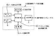
図1には情報提供端末4の概略構成が機能ブロックの組み合わせにより示されている。この図1において、情報提供端末4は、上記遊技データなどを表示するためのCRTディスプレイなどより成る比較的大形の表示部5(本発明でいう表示手段に相当)、表示部5の画面上に設定されたマトリックス方式の透明状タッチスイッチ6、集中管理コンピュータ3との間でデータの送受信を行うための入出力部7、後述する会員カード(図3に符号11を付して示す)の記憶データを読み込むためのカードリーダ8(本発明でいうデータ読み込み手段に相当)、データ記憶のための記憶部9(本発明でいうデータ登録手段に相当)、表示部5の表示制御や集中管理コンピュータ3との間のデータ送受信制御などを行うためのCPUを含んで成る制御部10(本発明でいうプリセット手段及び表示制御手段に相当)を備えた構成となっている。
【0025】
尚、制御部10は、マトリックス方式のタッチスイッチ6をスキャニングすることにより、当該タッチスイッチ6からその押圧操作位置を示す信号を受ける構成となっている。
【0026】
ここで、上記会員カード11は、本発明でいう記録担体に相当するものであり、例えばパチンコホールの遊技会員となった遊技客に対し1人1枚宛て発行される。この場合、会員カード11は、図3に示すように、その表面にテープ状の磁気記録部11aが設けられていると共に、加盟店名11b、加盟店及び会員に固有のデータに対応した数字列11c(「χ」は十進数を表現)、会員の氏名を示す文字列11d、カード有効年月日を示す数字列11eがエンボス加工によって形成されている。
【0027】
そして、上記磁気記録部11aには、例えばパチンコホールを特定するための加盟店コード、前記会員(遊技客)に割り当てられたIDコード、カード有効年月日を示す有効期限データなどが記録されている。
【0028】
しかして、図4〜図6には、情報提供端末4が有する制御部10による制御内容のうち本発明の要旨に関係した部分が示されており、以下これについて、表示部5による表示例を示した図7〜図15も参照しながら説明する。
【0029】
まず図4において、制御部10は、電源が投入された状態で表示部5に対して図7に示すような初期画面を表示する(ステップA1)。具体的には、この初期画面には、当日の日付を示す文字a1 、カードリーダ8への会員カード11の挿入を促すメッセージa2 が表示される。
【0030】
このように表示部5に初期画面を表示した状態では、カードリーダ8にカードが挿入されるまで待機する(ステップA2)。そして、カードリーダ8にカードが挿入されたときには、その挿入カードから読み込んだデータに基づいて、当該カードが適正な会員カード11であるか否かを判断する(ステップA3)。
【0031】
尚、この場合、カードリーダ8が読み込んだデータ中に会員カード11に記録されたIDコード及び有効期限データが存在するか否かに基づいて、挿入カードが会員カード11であるか否かを判断し、さらに、その会員カード11から読み込んだIDコード及び有効期限データを集中管理コンピュータ3側に蓄積されている顧客データベースと照会することにより、当該会員カード11が適正なものであるか否かを判断するものである。
【0032】
挿入された会員カード11が不適正なものであった場合には、その会員カード11を排出するステップA4を実行して初期画面表示ステップA1へ戻るが、適正なものであった場合には、表示部5に対し図8に示すようなメニュー選択画面を表示する(ステップA5)。
【0033】
具体的には、図8のメニュー選択画面には、当日の日付を示す文字b1 、選択対象メニューの内容を示す「遊技機情報」、「プリセット登録」、「インフォメーション」の各文字b2 、b3 、b4 及びこれらの文字b2 〜b4 を囲む枠、メニュー選択を促すメッセージb5 が表示される。
【0034】
このとき、メニュー選択画面中の文字b2 〜b4 に対応した部分が手指などにより押圧操作された各場合には、その操作位置が前記タッチスイッチ6のスキャニングに応じて特定されるようになっており、当該タッチスイッチ6にあっては、上記のような操作箇所が、それぞれ「遊技機情報」メニュー選択スイッチ(文字b2 部分)、「プリセット登録」メニュー選択スイッチ(文字b3 部分)、「インフォメーション」メニュー選択スイッチ(文字b4 部分)として機能するようになっている。
【0035】
上記メニュー選択画面を表示した状態では、上述した各メニュー選択スイッチ(文字b2 、b3 、b4 の各部分)を通じたメニュー選択操作の何れかが行われるまで待機する(ステップA6、A7、A8)。
【0036】
「インフォメーション」メニュー選択スイッチ(文字b4 部分)が操作された場合(ステップA8で「YES」)には、表示部5に対して、例えば、パチンコホールで行っている種々のサービスについての案内、遊技上の注意事項についての案内、その他の案内事項を所定時間だけ表示させるインフォメーション処理ルーチンA9を実行した後に、メニュー選択画面表示ステップA5へ戻る。
【0037】
「プリセット登録」メニュー選択スイッチ(文字b3 部分)が操作された場合(ステップA7で「YES」)には、図5に示すステップA10以降の制御を実行する。
【0038】
即ち、図5において、ステップA10では、表示部5に対し図9に示すような機種選択画面を表示する。具体的には、図9の機種選択画面には、当日の日付を示す文字c1 、パチンコホール内に設置されたパチンコ遊技機1についての全ての機種名を示す「ドリーム1」などの文字c2 群、「検索」、「台番指定」、「一覧確認」、「遊技台情報」、「終了」の各文字c3 、c4 、c5 、c6 、c7 及びこれらの文字c3 〜c7 を囲む枠が表示される。
【0039】
このとき、機種選択画面中の文字c2 〜c7 に対応した部分が手指などにより押圧操作された各場合には、その操作位置が前記タッチスイッチ6のスキャニングに応じて特定されるようになっており、当該タッチスイッチ6にあっては、上記のような操作箇所が、それぞれ機種選択スイッチ(文字c2 部分)、検索スイッチ(文字c3 部分)、台番指定スイッチ(文字c4 部分)、一覧確認スイッチ(文字c5 部分)、遊技台情報スイッチ(文字c6 部分)、終了スイッチ(文字c7 部分)として機能するようになっている。
【0040】
尚、機種選択スイッチ(文字c2 部分)が操作されたときには、当該機種選択スイッチに対応した機種名が反転表示などにより特定される構成となっており、これにより当該機種名が選択された旨を報知するようになっている。このような反転表示は、実際には複数の機種名について行い得る構成、つまり、複数の機種名を選択可能な構成となっているが、以下においては、説明の便宜上、一つの機種名のみ選択可能な構成であるものとし、また、機種選択画面の表示当初には、所定の機種名を自動的に反転表示することにより、当該機種名が自動選択された状態とする構成になっているものとする。
【0041】
上記のような機種選択画面の表示状態では、上述した検索スイッチ、台番指定スイッチ、一覧確認スイッチ、遊技機情報スイッチ、終了スイッチの何れかが操作されるまで待機する(ステップA11〜A15)。
【0042】
機種選択画面の表示状態で、検索スイッチ(文字c3 部分)が操作された場合(ステップA11で「YES」)には、表示部5に対し図10のような検索条件設定画面を表示する(ステップA16)。
【0043】
具体的には、図10の検索条件設定画面には、当日の日付を示す文字d1 、前記機種選択画面上で選択された機種名を示す文字d2 、例えば4種類の検索条件を示す「休止中の遊技機を検索」、「特賞回数χχ回以上を検索」、「特賞回数χχ回以下を検索」、「前回特賞終了後のスタート回数χχχχ回以上を検索」の各文字d3 、d4 、d5 、d6 (但し、χは十進数を表現)、テンキースイッチを示す「0」から「9」までの数字列d7 、上記した4種類の検索条件を選択するためのスイッチの位置を示す例えば「休止」、「特賞以上」、「特賞以下」、「スタート」の各文字d8 、d9 、d10、d11、「登録」、「取消」、「終了」の各文字d12、d13、d14及びこれら数字列d7 、文字d2 、d8 〜d14を囲む枠が表示される。
このとき、検索条件設定画面中の数字列d7 、文字d8 〜d14に対応した部分が手指などにより押圧操作された各場合には、その操作位置が前記タッチスイッチ6のスキャニングに応じて特定されるようになっており、当該タッチスイッチ6にあっては、上記のような操作箇所が、それぞれテンキースイッチ(数字列d7 部分)、検索条件選択スイッチ(文字d8 〜d11部分)、登録スイッチ(文字d12部分)、取消スイッチ(文字d13部分)、終了スイッチ(文字d14部分)として機能するようになっている。
【0044】
尚、検索条件を示す文字d3 〜d6 部分が押圧操作された各場合に、その操作箇所をタッチスイッチ6のスキャニングにより特定する構成としても良く、このような構成とした場合には、上記した検索条件選択スイッチを省略できることになる。
【0045】
また、検索条件を示す各文字d4 、d5 、d6 中の「χ」部分には、検索条件設定画面の表示当初において適宜の初期値が表示される構成となっている。例えば、文字d4 部分には「特賞回数10回以上を検索」と表示され、文字d5 部分には「特賞回数15回以下を検索」と表示され、文字d6 部分には「前回特賞終了後のスタート回数500回以上を検索」と表示される構成となっている。この場合、各文字d3 、d4 、d5 、d6 に対応した検索条件が、検索条件選択スイッチ(文字d8 〜d11部分)により選択された状態では、選択された検索条件を示す文字の全体が反転表示などにより特定されるようになっており、その選択は重複して行い得る構成となっている。さらに、文字d4 、d5 、d6 に対応した検索条件が選択された状態では、それら各文字d4 、d5 、d6 中の「χ」部分の表示数値を、前記キースイッチ(文字d7 部分)を通じた数値入力操作に応じて任意に変更できる構成となっている。
【0046】
しかして、上記検索条件設定画面を表示した状態では、上述のように検索条件選択スイッチにより選択された検索条件を受け付けて記憶する検索条件入力処理ルーチンA17を実行する。
【0047】
このルーチンA17の実行後には、前述した登録スイッチ(文字d12部分)、取消スイッチ(文字d13部分)、終了スイッチ(文字d14部分)の操作状態を判断し(ステップA18〜A20)、それらスイッチが何れも操作されていない状態では、検索条件入力処理ルーチンA17以降の制御を反復して実行する。
【0048】
検索条件設定画面の表示状態で、終了スイッチ(文字d14部分)が操作された場合(ステップA20で「YES」)には、前記機種選択画面表示ステップA10へ戻る。また、取消スイッチ(文字d13部分)が操作されたとき(ステップA19で「YES」)には、前記検索条件入力処理ルーチンA17で受け付けた検索条件をクリアするステップA21を実行した後に、当該検索条件入力処理ルーチンA17以降の制御を実行する。
【0049】
検索条件設定画面の表示状態で、登録スイッチ(文字d12部分)が操作された場合(ステップA18で「YES」)には、検索条件を受け付けた状態にあるか否かを判断し(ステップA22)、非受け付け状態では、表示部5中の余白スペースに例えば「検索条件が選択されていません」というようなメッセージを所定時間だけ表示し(ステップA23)、この後に検索条件入力処理ルーチンA17へ戻る。
【0050】
これに対して、上記登録スイッチの操作時において検索条件を受け付けた状態にあった場合(ステップA22で「YES」)には、検索条件登録処理ルーチンA24を実行した後に機種選択画面表示ステップA10へ戻る。
【0051】
この場合、上記検索条件登録処理ルーチンA24では、上述のように受け付けた状態にある検索条件と、カードリーダ8を通じて読み込んだIDコードとを対応付けた検索条件プリセットデータを作成し、この検索条件プリセットデータを記憶部9に登録(記憶)する。
【0052】
一方、前記機種選択画面の表示状態で、台番指定スイッチ(文字c4 部分)が操作された場合(ステップA12で「YES」)には、表示部5に対し図11のような台番号選択画面を表示する(ステップA25)。
【0053】
具体的には、図11の台番号選択画面には、当日の日付を示す文字e1 、前記機種選択画面上で選択された機種名を示す文字e2 、当該機種名に対応したパチンコ遊技機1の全ての台番号e3 、「登録」、「終了」の各文字e4 、e5 及び文字e2 、e4 、e5 を囲む枠が表示される。尚、上記台番号e3 の表示は、パチンコ遊技機1の設置時において例えば情報提供端末4側に予め記憶されているデータに基づいて行われるものである。
【0054】
このとき、台番号選択画面中の台番号e3 、文字e4 、e5 に対応した部分が手指などにより押圧操作された各場合には、その操作位置が前記タッチスイッチ6のスキャニングに応じて特定されるようになっており、当該タッチスイッチ6にあっては、上記のような操作箇所が、それぞれ台番選択スイッチ(台番号e3 部分)、登録スイッチ(文字e4 部分)、終了スイッチ(文字e5 部分)として機能するようになっている。
【0055】
尚、上記台番選択スイッチは、表示された多数の台番号e3 の中から所望のものを選択するためのもので、台番号e3 部分の操作毎に当該台番号e3 部分が反転表示状態及び通常表示状態に交互に切り換えられると共に、その反転表示による台番号の選択状態を報知するようになっており、その選択は重複して行い得る構成となっている。
【0056】
上記台番号選択画面を表示した状態では、登録スイッチ(文字e4 部分)、終了スイッチ(文字e5 部分)の何れかが操作されるまで待機し(ステップA26、A27)、終了スイッチが操作されたときには、そのまま前記機種選択画面表示ステップA10へ戻るが、登録スイッチが操作されたときには、台番号登録処理ルーチンA28を実行した後に機種選択画面表示ステップA10へ戻る。
【0057】
この場合、上記台番号登録処理ルーチンA28では、上述のように台番号選択スイッチにより選択された台番号(台番号選択画面中で反転表示された状態の台番号e3 に対応)と、カードリーダ8を通じて読み込んだIDコードとを対応付けた台番号プリセットデータを作成し、この台番号プリセットデータを記憶部9に登録(記憶)する。
【0058】
一方、前記機種選択画面の表示状態で、一覧確認スイッチ(文字c5 部分)が操作された場合(ステップA13で「YES」)には、表示部5に対し図12のようなプリセット内容確認画面を表示する(ステップA29)。
【0059】
具体的には、図12のプリセット内容確認画面には、当日の日付を示す文字f1 、前記検索条件選択画面上で登録された検索条件プリセットデータ及び前記台番選択画面上で登録された台番号プリセットデータが存在した場合に、それらのプリセットデータに対応した検索条件を示す文字f2 及び台番号を示す文字f3 を表示し、また、「一括削除」、「削除」、「終了」の文字f4 、f5 、f6 及びそれら文字f4 、f5 、f6 を囲む枠が表示される。但し、上記検索条件プリセットデータ及び台番号プリセットデータが未登録の場合には、上記文字f2 〜f6 に代えて、例えば、プリセットデータが登録されていない旨を知らせるメッセージを表示する構成となっている。
【0060】
このとき、プリセット内容確認画面中の文字f2 〜f6 に対応した部分が手指などにより押圧操作された各場合には、その操作位置が前記タッチスイッチ6のスキャニングに応じて特定されるようになっており、当該タッチスイッチ6にあっては、上記のような操作箇所が、それぞれ削除対象選択スイッチ(文字f2 、f3 部分)、一括削除スイッチ(文字f4 部分)、削除スイッチ(文字f5 部分)、終了スイッチ(文字f6 部分)として機能するようになっている。
【0061】
尚、上記削除対象選択スイッチは、前記検索条件プリセットデータ及び台番号プリセットデータのうち削除対象のデータを選択するためのもので、その操作毎に対応する文字f2 、f3 部分が反転表示状態及び通常表示状態に交互に切り換えられると共に、その反転表示により上記選択状態を報知するようになっており、その選択は重複して行い得る構成となっている。
【0062】
上記プリセット内容確認画面を表示した状態では、前記一括削除(文字f4 部分)、削除スイッチ(文字f5 部分)、終了スイッチ(文字f6 部分)の何れかが操作されるまで待機し(ステップA30、A31)、終了スイッチが操作されたときには、そのまま前記機種選択画面表示ステップA10へ戻るが、一括削除スイッチまたは削除スイッチが操作されたときには、プリセットデータ削除処理ルーチンA32を実行した後に、上記判断ステップA30へ戻る。
【0063】
この場合、上記プリセットデータ削除処理ルーチンA32では、削除スイッチの操作時には、前記記憶部9中から上述のように削除対象選択スイッチにより選択された削除対象の検索条件プリセットデータ及び台番号プリセットデータを削除し、また、一括削除スイッチの操作時には、記憶部9中の検索条件プリセットデータ及び台番号プリセットデータを一括して削除する。
【0064】
一方、前記機種選択画面の表示状態で、遊技台情報スイッチ(文字c6 部分)が操作された場合(ステップA14で「YES」)には、記憶部9中に検索条件プリセットデータ及び台番号プリセットデータが登録されているか否かを判断し(ステップA33)、非登録状態では、表示部5中の余白スペースに例えば「プリセットデータが登録されていません」というようなメッセージを所定時間だけ表示し(ステップA34)、この後に判断ステップA11へ戻る。
【0065】
これに対して、上記遊技台情報スイッチの操作時において記憶部9中に検索条件プリセットデータ及び台番号プリセットデータが登録された状態にあった場合(ステップA33で「YES」)には、図6に示す後述の検索処理ルーチンA46以降の制御を実行する。
【0066】
さらに、機種選択画面の表示状態で、終了スイッチ(文字c7 部分)が操作された場合(ステップA15で「YES」)には、前記メニュー選択画面表示ステップA5へ戻る。
【0067】
メニュー選択画面(図8参照)の表示状態で、「遊技機情報」メニュー選択スイッチ(文字b2 部分)が操作された場合(図4のステップA6で「YES」)には、図6に示すステップA35以降の制御を実行する。
【0068】
即ち、図6において、ステップA35では、表示部5に対し図13(a)のような遊技機情報一覧画面を表示する。具体的には、図13(a)の遊技機情報一覧画面には、当日の日付及び現在時刻を示す文字g1 、「大当たり回数/スタート回数」の文字g2 、「2日前、前日、本日」の文字g3 、この文字g3 に対応したデータ表示エリアΔA(台番号の入力位置を指し示すカーソルC(この例では斜線帯により示した反転表示によるカーソル)を含む)、テンキースイッチを示す「0」から「9」までの数字列g4 、上記カーソル及び画面スクロール用のスイッチを示すアイコンg5 、「実行」、「プリセット」、「出玉」、「履歴」、「登録」、「終了」の各文字g6 〜g10及びこれらの数字列g4 、文字g6 〜g11を囲む枠が表示される。
【0069】
このとき、遊技機情報一覧画面中の数字列g4 、アイコンg5 、文字g6 〜g11に対応した部分が手指などにより押圧操作された各場合には、その操作位置が前記タッチスイッチ6のスキャニングに応じて特定されるようになっており、当該タッチスイッチ6にあっては、上記のような操作箇所が、それぞれテンキースイッチ(数字列g4 部分)、スクロールスイッチ(アイコンg5 部分)、実行スイッチ(文字g6 部分)、プリセットデータスイッチ(文字g7 部分)、出玉推移グラフ選択スイッチ(文字g8 部分)、特賞履歴選択スイッチ(文字g9 部分)、登録スイッチ(文字g10部分)、終了スイッチ(文字g11部分)として機能するようになっている。
【0070】
尚、前記データ表示エリアΔA中においてカーソルCによって指し示される台番号入力位置には、前記テンキースイッチにより任意の台番号を入力して表示可能な構成となっており、また、カーソルCの位置を前記スクロールスイッチにより移動させることにより、任意数の台番号を入力して表示できるようになっている。
【0071】
上記遊技機情報一覧画面を表示した状態では、上述のようにテンキースイッチにより入力された台番号を受け付けて記憶する台番号入力処理ルーチンA36を実行し、この後には、前述した実行スイッチ(文字g6 部分)、プリセットデータスイッチ(文字g7 部分)、出玉推移グラフ選択スイッチ(文字g8 部分)、特賞履歴選択スイッチ(文字g9 部分)、登録スイッチ(文字g10部分)、終了スイッチ(文字g11部分)の操作状態を判断し(ステップA37〜A42)、それらスイッチが何れも操作されていない状態では、台番号入力処理ルーチンA36以降の制御を反復して実行する。
【0072】
遊技機情報一覧画面の表示状態で、実行スイッチ(文字g6 部分)が操作された場合(ステップA37で「YES」)には、前記台番号入力処理ルーチンA36において台番号を受け付けた状態にあるか否かを判断し(ステップA43)、非受け付け状態では、表示部5中の余白スペースに例えば「台番号が指定されていません」というようなメッセージを所定時間だけ表示し(ステップA44)、この後に台番号入力処理ルーチンA36へ戻る。
【0073】
これに対して、上記実行スイッチの操作時において台番号を受け付けた状態にあった場合(ステップA43で「YES」)には、指定遊技機情報表示処理ルーチンA45を実行した後に台番号入力処理ルーチンA36へ戻る。
【0074】
この場合、上記指定遊技機情報表示処理ルーチンA45では、集中管理コンピュータ3に蓄積された累計データ(前記▲1▼の説明参照)の中から、前述のように受け付けた状態にある台番号のパチンコ遊技機1に関する累計特賞回数を示すデータを、当日を含む過去3日分について読み出すと共に、同じく集中管理コンピュータ3に蓄積されたスタート回数データ(前記▲3▼の説明参照)の中から、受け付け状態にある台番号のパチンコ遊技機1に関するものを読み出して、その読み出しデータを、表示部5中のデータ表示エリアΔAに対し図13(b)のように表示する。尚、このデータ表示エリアΔAには、該当パチンコ遊技機1の台番号及び機種も同時に表示されるようになる。
【0075】
一方、遊技機情報一覧画面の表示状態で、プリセットデータスイッチ(文字g7 部分)が操作された場合(ステップA38で「YES」)には、検索処理ルーチンA46を実行する。
【0076】
この検索処理ルーチンA46では、記憶部9中に登録されている検索条件プリセットデータ群及び台番号プリセットデータ群を検索して、会員カード11からカードリーダ8を通じて読み込んだIDコードを含むものを抽出する動作を行うものであり、このルーチンA46の実行後には、該当IDコードを含むプリセットデータが抽出されたか否かを判断する(ステップA47)。
【0077】
このステップA47で「NO」と判断した場合、つまりカードリーダ8に挿入された会員カード11のIDコードに対応した検索条件プリセットデータ或いは台番号プリセットデータが未登録であった場合には、表示部5中の余白スペースに例えば「プリセットされたデータがありません」というようなメッセージを所定時間だけ表示し(ステップA48)、この後に台番号入力処理ルーチンA36へ戻るが、「YES」と判断した場合には、プリセットデータ表示処理ルーチンA49を実行した後に台番号入力処理ルーチンA36へ戻る。
【0078】
上記プリセットデータ表示処理ルーチンA49では、集中管理コンピュータ3に蓄積された累計データ(前記▲1▼の説明参照)の中から、既登録の検索条件プリセットデータ或いは台番号プリセットデータ(カードリーダ8に挿入された会員カード11のIDコードに対応したデータ)により特定されるパチンコ遊技機1に関する累計特賞回数を示すデータを、当日を含む過去3日分について読み出すと共に、同じく集中管理コンピュータ3に蓄積されたスタート回数データ(前記▲3▼の説明参照)の中から、上記プリセットデータにより特定されるパチンコ遊技機1に関するものを読み出して、その読み出しデータを、表示部5中のデータ表示エリアΔAに対し表示する。
【0079】
一方、遊技機情報一覧画面の表示状態で、出玉推移グラフ選択スイッチ(文字g8 部分)が操作された場合(ステップA39で「YES」)には、表示部5に対し図14に示すような出玉推移グラフ画面を表示する(ステップA50)。
【0080】
具体的には、図14の出玉推移グラフ画面には、当日の日付及び現在時刻を示す文字h1 、「出玉推移グラフ」の文字h2 、上記遊技機情報一覧画面に表示されている台番号(スクロールスイッチの操作に応じて表示状態となる台番号も含む)のパチンコ遊技機1に係る出玉推移グラフΔG、画面スクロール用のスイッチを示すアイコンh3 、「一覧」、「履歴」、「登録」、「終了」の各文字h4 〜h7 及びこれらの文字h4 〜h7 を囲む枠が表示される。
【0081】
このとき、アイコンh3 、文字h4 〜h7 に対応した部分が押圧操作された各場合には、その操作位置が前記タッチスイッチ6のスキャニングに応じて特定されるようになっており、当該タッチスイッチ6にあっては、上記のような操作箇所が、それぞれスクロールスイッチ(アイコンh3 部分)、一覧画面選択スイッチ(文字h4 部分)、特賞履歴選択スイッチ(文字h5 部分)、登録スイッチ(文字h6 部分)、終了スイッチ(文字h7 部分)として機能するようになっている。
【0082】
また、上記出玉推移グラフΔGは、集中管理コンピュータ3に蓄積された履歴グラフ作成用データ(前記▲2▼の説明参照)に基づいて作成されるもので、その履歴グラフ作成用データのうち当日分の各データについて1画面分ずつの出玉推移グラフΔGを得るようになっており、このグラフΔG中には、該当パチンコ遊技機1の台番号及び機種も同時に表示される。
【0083】
この場合、出玉推移グラフΔGは、履歴グラフ作成用データ中の特賞発生時点及び特賞終了時点の各累計アウト玉数を横軸とし、特賞発生時点及び特賞終了時点の各差玉数を縦軸として作成されるものであり、このグラフΔGからはパチンコ遊技機1における出玉の推移状態が一目で分かるようになる。
【0084】
尚、出玉推移グラフΔGは、遊技機情報一覧画面に表示されている台番号のパチンコ遊技機1について全て作成されるものであり、未表示状態の出玉推移グラフΔGについては、スクロールスイッチ(アイコンh3 部分)の操作に応じて選択的に表示される構成となっている。また、集中管理コンピュータ3側に蓄積された履歴グラフ作成用データは、当日を含む過去3日分のデータであるから、3日分の出玉推移グラフを一度に表示する構成とすることも可能である。
【0085】
上記出玉推移グラフ画面を表示した状態では、特賞履歴選択スイッチ(文字h5 部分)、一覧画面選択スイッチ(文字h4 部分)、終了スイッチ(文字h7 部分)、登録スイッチ(文字h6 部分)の何れかが操作されるまで待機する(ステップA51〜A54)。
【0086】
出玉推移グラフ画面を表示した状態で、終了スイッチ(文字h7 部分)が操作されたとき(ステップA53で「YES」)には、前記メニュー選択画面表示ステップA5(図4参照)へ戻り、一覧画面選択スイッチ(文字h4 部分)が操作されたとき(ステップA52で「YES」)には、前記遊技機情報一覧画面表示ステップA35へ戻る。
【0087】
また、出玉推移グラフ画面を表示した状態で、特賞履歴選択スイッチ(文字h5 部分)が操作されたとき(ステップA51で「YES」)には、後述する特賞履歴画面表示ステップA56へ移行し、登録スイッチ(文字h6 部分)が操作されたときには、台番号登録処理ルーチンA55を実行した後に、前記台番号入力処理ルーチンA36へ戻る。この場合、上記台番号登録処理ルーチンA55では、前記遊技機情報一覧画面中に表示されている台番号(スクロールスイッチの操作により初めて表示される表示待機状態の台番号も含む)と、カードリーダ8を通じて読み込んだIDコードとを対応付けた台番号プリセットデータを作成し、この台番号プリセットデータを記憶部9に登録(記憶)する。
【0088】
一方、遊技機情報一覧画面の表示状態で、特賞履歴選択スイッチ(文字g9 部分)が操作された場合(ステップA40で「YES」)には、表示部5に対し図15に示すような特賞履歴画面を表示する(ステップA56)。尚、このステップA56は、前述したようにステップA51で「YES」と判断されたときにも実行される。
【0089】
具体的には、図15の特賞履歴画面には、当日の日付及び現在時刻を示す文字j1 、「特賞履歴」の文字j2 、前記遊技機情報一覧画面に表示されている台番号(スクロールスイッチの操作に応じて表示状態となる台番号も含む)のパチンコ遊技機1に係る特賞履歴グラフΔH、画面スクロール用のスイッチを示すアイコンj3 、「一覧」、「出玉」、「登録」、「終了」の各文字j4 〜j7 及びこれらの文字j4 〜j7 を囲む枠が表示される。
【0090】
このとき、アイコンj3 、文字j4 〜j7 に対応した部分が押圧操作された各場合には、その操作位置が前記タッチスイッチ6のスキャニングに応じて特定されるようになっており、当該タッチスイッチ6にあっては、上記のような操作箇所が、それぞれスクロールスイッチ(アイコンj3 部分)、一覧画面選択スイッチ(文字j4 部分)、出玉推移グラフ選択スイッチ(文字j5 部分)、登録スイッチ(文字j6 部分)、終了スイッチ(文字j7 部分)として機能するようになっている。
【0091】
また、上記特賞履歴グラフΔHは、集中管理コンピュータ3に蓄積された履歴グラフ作成用データ(前記▲2▼の説明参照)に基づいて作成されるもので、当日を含む過去3日分についての履歴グラフ作成用データに基づいた特賞履歴グラフΔHを得るようになっており、このグラフΔH中には、対応する位置に「2日前」、「1日前」、「本日」の各文字が表示されると共に、該当パチンコ遊技機1の台番号及び機種も同時に表示される。
【0092】
この場合、特賞履歴グラフΔHは、履歴グラフ作成用データ中の特賞発生時点の累計アウト玉数データに基づいて、特賞発生時点を時間軸(当日を含む過去3日分)である横軸にプロット(「$」印)することにより作成されるものであり、このグラフΔHからは、パチンコ遊技機1における特賞状態の発生履歴が過去3日分について一目で分かるようになる。
【0093】
尚、特賞履歴グラフΔHは、遊技機情報一覧画面に表示されている台番号のパチンコ遊技機1について全て作成されるものであり、未表示状態の特賞履歴グラフΔHについては、スクロールスイッチ(アイコンj3 部分)の操作に応じて選択的に表示される構成となっている。
【0094】
上記特賞履歴画面を表示した状態では、一覧画面選択スイッチ(文字j4 部分)、出玉推移グラフ選択スイッチ(文字j5 部分)、終了スイッチ(文字j7 部分)、登録スイッチ(文字j6 部分)の何れかが操作されるまで待機する(ステップA57〜A60)。
【0095】
特賞履歴画面を表示した状態で、終了スイッチ(文字j7 部分)が操作されたとき(ステップA59で「YES」)には、前記メニュー選択画面表示ステップA5へ戻り、一覧画面選択スイッチ(文字j4 部分)が操作されたとき(ステップA57で「YES」)には、前記遊技機情報一覧画面表示ステップA35へ戻る。
【0096】
また、特賞履歴画面を表示した状態で、出玉推移グラフ選択スイッチ(文字j5 部分)が操作されたとき(ステップA58で「YES」)には、前記出玉推移グラフ画面表示ステップA50へ移行し、登録スイッチ(文字j6 部分)が操作されたときには、前述した台番号登録処理ルーチンA55と同一内容の台番号登録処理ルーチンA61を実行した後に、前記台番号入力処理ルーチンA36へ戻る。
【0097】
一方、図13に示す遊技機情報一覧画面を表示した状態で、登録スイッチ(文字g10部分)が操作された場合(ステップA41で「YES」)には、前述した台番号登録処理ルーチンA55及びA61と同一内容の台番号登録処理ルーチンA62を実行した後に、前記台番号入力処理ルーチンA36へ戻る。
【0098】
さらに、遊技機情報一覧画面の表示状態で、終了スイッチ(文字g11部分)が操作された場合(ステップA42で「YES」)には、前記メニュー選択画面表示ステップA5へ戻る。
【0099】
要するに、上記した本実施例の構成によれば、会員カード11の発行を受けた遊技客は、記憶部9に対して、所望の検索条件及び台番号をそれぞれ検索条件プリセットデータ及び台番号プリセットデータとして予め登録しておけば、その検索を満たすパチンコ遊技機1に係る遊技データ、或いは上記台番号に対応したパチンコ遊技機1に係る遊技データを、情報提供端末4に対してきわめて簡単な操作で表示させ得るものである。
【0100】
具体的には、上記のような表示のためには、カードリーダ8に会員カード11を挿入した状態において、当該情報提供端末4の表示部5に表示されるメニュー選択画面(図8参照)中の「遊技機情報」メニュー選択スイッチ(文字b2 部分)を押圧操作するだけで良く、このような操作に応じて、予め登録したパチンコ遊技機1に係る遊技データを、図13に示すような形態の遊技機情報一覧画面として表示させ得るようになる。また、このような表示状態では、予め登録したパチンコ遊技機1に係る出玉推移グラフ(図14参照)や特賞履歴グラフ(図15参照)の遊技データも、きわめて容易な操作により表示させ得るようになる。
【0101】
従って、情報提供端末4において、所望の遊技データを表示させるために必要となる操作の所要時間を短縮できて、当該情報提供端末4における遊技客1人当たりの占有時間を短縮できるようになるから、その利用者数の増大及びこれに伴う集客力アップ効果を十分に発揮できるようになる。
【0102】
また、上記台番号プリセットデータには、多数台のパチンコ遊技機1の台番号を含ませることが可能であるから、多数台のパチンコ遊技機1に係る遊技データを表示させる場合でも、その表示のための操作に要する時間を飛躍的に減少させることができ、遊技客1人当たりの占有時間の短縮に大きく寄与できることになる。さらに、上記検索条件プリセットデータは、遊技客が指定した検索条件に合致したものが自動的に抽出されて登録される構成であるから、実用上において非常に有益となる。
【0103】
尚、本発明は上記した実施例に限定されるものではなく、次のような変形または拡張が可能である。
データ登録手段として、情報提供端末4側に設けた記憶部9を利用したが、例えば、会員カード11の磁気記録部11aに対して検索条件プリセットデータ及び台番号プリセットデータを磁気記録する構成、つまり当該磁気記録部11aをデータ登録手段として用いる構成としても良い。但し、この場合にはデータ読込手段として、カードリーダ8に代えて、上記磁気記録部11aに対しデータ書き込み可能なカードリーダライタを使用することになる。また、会員カードをICカード或いはICメモリカードにより構成しても良い。記録担体としては、上記のような会員カード11に限られるものではなく、プリペイドカードを記録担体として利用する構成も可能である。
【0104】
検索条件として、「休止中の遊技機」、「特賞回数が所定回数以上」、「特賞回数が所定回数以下」、「前回特賞終了後のスタート回数」を例に挙げたが、特賞確率(累計特賞回数÷累計スタート回数)、打止回数などを検索条件として設定することも可能である。データ記憶手段として集中管理コンピュータ3を設けるようにしたが、当該データ記憶手段の機能を情報提供端末4に持たせる構成も可能である。
【0105】
会員カード11がカードリーダ8に挿入されたときにおいて、記憶部9に当該会員カード11に対応したプリセットデータが記憶されていた場合には、そのプリセットデータに該当した遊技データを表示部5に直ちに表示させる構成としても良い。
【0106】
【発明の効果】
本発明によれば以上の説明によって明らかなように、遊技機の台番号と対応付けた状態のプリセットデータ、或いは遊技機に係る遊技データの種類に応じた検索条件と対応付けたプリセットデータを、記録担体のIDコードと対応付けた状態で予め登録しておき、データ記憶手段が上記記録担体のIDコードを読み込むのに応じて、上記プリセットデータに対応した台番号の遊技機に関する遊技データ、或いはプリセットデータ中の検索条件に対応した遊技データを表示部に表示させる構成としたから、その表示のために必要な操作に要する時間を短縮できて、遊技客1人当たりの占有時間を短縮でき、これにより利用者数の増大を図り得るようになるという有益な効果を奏するものである。
【図面の簡単な説明】
【図1】本発明の一実施例の要部を構成する情報提供端末の電気的構成を示す機能ブロック図
【図2】全体の電気的構成を示す機能ブロック図
【図3】会員カードの正面図
【図4】情報提供端末が有する制御部の制御内容を示すフローチャートその1
【図5】情報提供端末が有する制御部の制御内容を示すフローチャートその2
【図6】情報提供端末が有する制御部の制御内容を示すフローチャートその3
【図7】情報提供端末が有する表示部による表示例を示す図その1
【図8】情報提供端末が有する表示部による表示例を示す図その2
【図9】情報提供端末が有する表示部による表示例を示す図その3
【図10】情報提供端末が有する表示部による表示例を示す図その4
【図11】情報提供端末が有する表示部による表示例を示す図その5
【図12】情報提供端末が有する表示部による表示例を示す図その6
【図13】情報提供端末が有する表示部による表示例を示す図その7
【図14】情報提供端末が有する表示部による表示例を示す図その8
【図15】情報提供端末が有する表示部による表示例を示す図その9
【符号の説明】
図面中、1はパチンコ遊技機、2は呼び出しランプユニット、3は集中管理コンピュータ(データ記憶手段)、4は情報提供端末(遊技場用データ表示装置)、5は表示部(表示手段)、6はタッチスイッチ、8はカードリーダ(データ読み込み手段)、9は記憶部(データ登録手段)、10は制御部(プリセット手段、表示制御手段)、11は会員カード(記録担体)を示す。[0001]
BACKGROUND OF THE INVENTION
The present invention relates to a game field data display apparatus having display means for selectively displaying a plurality of types of game data relating to a large number of gaming machines installed in a game hall.
[0002]
[Problems to be solved by the invention]
In the pachinko hall, by providing information that is useful to the player among the multiple types of game information related to pachinko machines installed in the store, the pachinko hall will improve the interest and expectation of the game in the pachinko hall Attempts have been made to tie this up to the ability to attract customers.
[0003]
Specifically, conventionally, a data display device having a display means such as a CRT display and a key switch for operation is installed at an appropriate place in the pachinko hall, and the display means for the pachinko gaming machine is placed on the display means. The game data such as the rate, the number of occurrences of the special prize state and the occurrence history, and the number of occurrences of the hit state can be selectively displayed on the screen.
[0004]
Since the data display device as described above is relatively expensive, it is usually installed at one or two places in the pachinko hall. However, when the player uses the data display device, the game data is not stored. There is a situation that a relatively long time is required for the operation for calling on the screen. For this reason, the occupied time per player is prolonged, and there is a problem that many players cannot use the game. Such a problem is caused by the player using a data display device for various games. The general situation that there are many cases of confirming the data has made it easy to expand. Therefore, as a result, it is inevitable that the number of users of the data display device is limited, and the original purpose of increasing the ability to attract customers may not be sufficiently achieved.
[0005]
The present invention has been made in view of the above circumstances, and its purpose is to selectively display necessary data from a plurality of types of game data related to the gaming machine, and the time required for the operation for the display. It is an object of the present invention to provide a data display device for a game hall that can shorten the occupation time per player and thereby increase the number of users.
[0006]
[Means for Solving the Problems]
In order to achieve the above object, the present invention comprises data storage means for storing a plurality of types of game data relating to a large number of gaming machines installed in a game arcade in a state in which the game data is associated with the machine number of the gaming machine. Game data provided in the game hall and stored in the data storage means Game data selected by the player's operation from In a data display device for a game hall having a display means for displaying,
Player's A data reading means for reading the ID code from a record carrier on which the ID code is recorded; Selected by the player Data registration means for storing preset data in a state in which the machine number of the gaming machine is associated, and storage of the preset data to the data registration means is allowed only when the data reading means has read the ID code In the state where the data reading means has read the ID code, only when preset data containing the ID code is stored in the data registration means, The display control means for reading game data corresponding to the machine number in the preset data and displaying it on the display means is provided.
[0007]
In such a configuration, a record carrier on which an ID code unique to the player is recorded is issued to the player. When a player who has issued a record carrier causes the display means to display game data related to the gaming machine he / she wants to know among a plurality of types of game data related to a large number of gaming machines stored in the data storage means Is ,Up Record carrier ID code and And the machine number of the gaming machine selected by the player Preset data in the associated state is pre-registered in the data registration means. At the time of registration, when the ID code of the record carrier is read by the data reading means, the preset means stores the preset data for the data registration means. Since the storage is permitted, the preset data is registered in this permitted state.
[0008]
When preset data is registered as described above, when the ID code of the record carrier is read by the data reading means, the display control means stores the preset data including the ID code in the data registration means. Only in this case, game data corresponding to the machine number in the preset data is read from the data storage means and displayed on the display means.
[0009]
Therefore, if preset data is registered in advance, when displaying game data relating to a desired gaming machine on the display means, it is only necessary to perform a simple operation of causing the reading means to read the ID code of the record carrier. As a result, it is possible to reduce the time required for the operation required for displaying the desired game data, and to reduce the occupation time per player. In this case, since the preset data can include a number of game machines, even when game data relating to a large number of gaming machines is displayed, an operation for displaying the game data is required. The time can be drastically reduced, which can greatly contribute to the reduction of the occupied time per player (claim 1).
[0010]
Further, the data registration means is connected to the ID code Selected by the player Machine number When Instead of preset data in a state where , ID code and Selected by the player The display control means is configured to store the preset data in association with the search condition corresponding to the type of game data, and the data registration means in the state where the reading means reads the ID code. The game data corresponding to the search condition in the preset data is read from the data storage means and displayed on the display means only when preset data including the ID code is stored in the data storage means. .
[0011]
Even in such a configuration, a record carrier in which an ID code unique to the player is recorded is issued to the player. The player who has issued the record carrier is the type of game data he / she wants to know among the multiple types of game data stored in the data storage means (for example, the cumulative number of jackpots in the game machine). When displaying game data on the display means ,Up Record carrier ID code and A search condition corresponding to the type of game data selected by the player It is registered in advance in the data registration means as preset data in the associated state, and this registration is performed in a state where the ID code of the record carrier is read by the data reading means.
[0012]
When preset data is registered as described above, when the ID code of the record carrier is read by the data reading means, the display control means stores the preset data including the ID code in the data registration means. Only in this case, game data corresponding to the search condition in the preset data is read from the data storage means and displayed on the display means.
[0013]
Therefore, in this case as well, if preset data is registered in advance, a simple operation is performed in which the ID code of the record carrier is read by the reading means when the game data relating to the desired gaming machine is displayed on the display means. As a result, the occupancy time per player can be shortened. In this case, the preset data can include search conditions corresponding to a plurality of types of game data. Therefore, even when game data relating to a large number of gaming machines is displayed, an operation for the display is performed. Time can be drastically reduced, which can greatly contribute to shortening the occupation time per player (claim 2).
[0014]
DETAILED DESCRIPTION OF THE INVENTION
Hereinafter, an embodiment in which the present invention is applied to a pachinko hall will be described with reference to the drawings.
In FIG. 2 showing the overall configuration, a number of
[0015]
The
[0016]
Here, the
[0017]
Further, the
[0018]
Here, the
[0019]
In this case, in the
[0020]
(1) ... Data indicating the date of each business day, the total number of out balls, the total number of safe balls, the total number of start balls (the number of wins in the start winning hole), the total number of special prizes, for each
[0021]
(2): History data indicating the cumulative number of out balls and the number of difference balls (out ball count-safe ball count) at each time point when the special prize is generated in the
[0022]
(3): Start frequency data indicating the number of start times after the special prize is generated. However, this start count data is initialized every time a special prize is newly generated, and after that, the start count after the end of the special prize is sequentially accumulated. Therefore, it is called the latest data on that day. It will be.
[0023]
Furthermore, the
[0024]
FIG. 1 shows a schematic configuration of the
[0025]
The
[0026]
Here, the membership card 11 corresponds to the record carrier in the present invention, and is issued, for example, to each player who becomes a gaming member of a pachinko hall. In this case, as shown in FIG. 3, the member card 11 is provided with a tape-like
[0027]
In the
[0028]
4 to 6 show a part related to the gist of the present invention in the contents of control by the
[0029]
First, in FIG. 10 Displays an initial screen as shown in FIG. 7 on the
[0030]
In the state where the initial screen is displayed on the
[0031]
In this case, it is determined whether the inserted card is the member card 11 based on whether the ID code recorded on the member card 11 and the expiration date data are present in the data read by the
[0032]
If the inserted membership card 11 is improper, execute step A4 to eject the membership card 11 and return to the initial screen display step A1, but if it is appropriate, A menu selection screen as shown in FIG. 8 is displayed on the display unit 5 (step A5).
[0033]
Specifically, the menu selection screen of FIG. 8 includes characters b1 indicating the date of the current day, “gaming machine information”, “preset registration”, and “information” characters b2, b3, b4, a frame surrounding these characters b2 to b4, and a message b5 prompting menu selection are displayed.
[0034]
At this time, when the portion corresponding to the characters b2 to b4 in the menu selection screen is pressed with a finger or the like, the operation position is specified in accordance with the scanning of the
[0035]
In the state where the menu selection screen is displayed, it waits until any of the menu selection operations through the menu selection switches (characters b2, b3, b4) is performed (steps A6, A7, A8).
[0036]
When the “information” menu selection switch (character b4 portion) is operated (“YES” in step A8), the
[0037]
When the “preset registration” menu selection switch (character b3 portion) is operated (“YES” in step A7), the control after step A10 shown in FIG. 5 is executed.
[0038]
That is, in FIG. 5, in step A10, a model selection screen as shown in FIG. Specifically, the model selection screen in FIG. 9 includes characters c1 indicating the date of the day, and characters c2 such as “
[0039]
At this time, when the part corresponding to the characters c2 to c7 on the model selection screen is pressed with a finger or the like, the operation position is specified in accordance with the scanning of the
[0040]
When the model selection switch (character c2 portion) is operated, the model name corresponding to the model selection switch is specified by reverse display, etc., so that the model name is selected. It has come to inform. Such reverse display is actually a configuration that can be performed for a plurality of model names, that is, a configuration in which a plurality of model names can be selected, but in the following, for convenience of explanation, only one model name is selected. It is assumed that the configuration is possible, and at the beginning of the display of the model selection screen, the model name is automatically selected by automatically highlighting and displaying the model name. And
[0041]
In the display state of the model selection screen as described above, the process waits until any of the above-described search switch, machine number designation switch, list confirmation switch, gaming machine information switch, or end switch is operated (steps A11 to A15).
[0042]
When the search switch (character c3 portion) is operated in the display state of the model selection screen (“YES” in step A11), a search condition setting screen as shown in FIG. A16).
[0043]
Specifically, the search condition setting screen of FIG. 10 includes a character d1 indicating the date of the current day, a character d2 indicating the model name selected on the model selection screen, for example, “pause” indicating four types of search conditions. "Search for gaming machines of", "Search for special prize number χχ or more", "Search for special prize number χχ or less", "Search for start number χχχχ times or more after last special prize" d3, d4, d5, d6 (where χ represents a decimal number), a numeric string d7 from “0” to “9” indicating a numeric key switch, and the position of the switch for selecting the above four types of search conditions, for example, “pause” , “Special Award or higher”, “Special Award or lower”, “Start”
At this time, when each of the portions corresponding to the number string d7 and the characters d8 to d14 on the search condition setting screen is pressed with a finger or the like, the operation position is specified according to the scanning of the
[0044]
It should be noted that in each case where the characters d3 to d6 indicating the search conditions are pressed, the operation location may be specified by scanning the
[0045]
In addition, an appropriate initial value is displayed at the beginning of the display of the search condition setting screen in the “χ” portion in each of the characters d4, d5, and d6 indicating the search condition. For example, “Search for 10 or more special prizes” is displayed in the character d4 portion, “Search for 15 or less special prizes” is displayed in the character d5 portion, and “Start after the last special award ends” “Search for 500 times or more” is displayed. In this case, when the search conditions corresponding to the characters d3, d4, d5, and d6 are selected by the search condition selection switch (characters d8 to d11), the entire character indicating the selected search condition is highlighted. The selection can be performed redundantly. Further, in the state where the search conditions corresponding to the characters d4, d5, d6 are selected, the display numerical value of the "χ" portion in each of the characters d4, d5, d6 is a numerical value obtained through the key switch (character d7 portion). The configuration can be changed arbitrarily according to the input operation.
[0046]
When the search condition setting screen is displayed, the search condition input processing routine A17 for receiving and storing the search condition selected by the search condition selection switch as described above is executed.
[0047]
After execution of this routine A17, the operation states of the registration switch (character d12 portion), cancel switch (character d13 portion), and end switch (character d14 portion) described above are determined (steps A18 to A20). If no operation is performed, the control after the search condition input processing routine A17 is repeatedly executed.
[0048]
If the end switch (character d14 portion) is operated in the display state of the search condition setting screen (“YES” in step A20), the process returns to the model selection screen display step A10. When the cancel switch (character d13 portion) is operated (“YES” in step A19), after executing step A21 that clears the search condition accepted in the search condition input processing routine A17, the search condition The control after input processing routine A17 is executed.
[0049]
When the registration switch (character d12 portion) is operated in the display state of the search condition setting screen (“YES” in step A18), it is determined whether or not the search condition is accepted (step A22). In the non-accepting state, a message such as “No search condition is selected” is displayed in the blank space in the
[0050]
On the other hand, if the search condition is accepted when the registration switch is operated ("YES" in step A22), the search condition registration process routine A24 is executed and then the model selection screen display step A10 is performed. Return.
[0051]
In this case, in the search condition registration processing routine A24, search condition preset data in which the search condition in the received state as described above is associated with the ID code read through the
[0052]
On the other hand, when the machine number designation switch (character c4 portion) is operated in the display state of the model selection screen (“YES” in step A12), the machine number selection screen as shown in FIG. Is displayed (step A25).
[0053]
Specifically, the machine number selection screen of FIG. 11 includes a character e1 indicating the date of the day, a character e2 indicating the model name selected on the model selection screen, and the
[0054]
At this time, when each of the portions corresponding to the table number e3, characters e4 and e5 in the table number selection screen is pressed with a finger or the like, the operation position is specified in accordance with the scanning of the
[0055]
The machine number selection switch is for selecting a desired machine number from among the displayed machine numbers e3. Each time the machine number e3 part is operated, the machine number e3 part is displayed in an inverted display state or in a normal state. In addition to being switched alternately to the display state, the selection state of the unit number by the reverse display is notified, and the selection can be performed redundantly.
[0056]
In the state in which the above-mentioned machine number selection screen is displayed, it waits until either the registration switch (character e4 portion) or the end switch (character e5 portion) is operated (steps A26 and A27), and when the end switch is operated. The process returns to the model selection screen display step A10 as it is, but when the registration switch is operated, the unit number registration processing routine A28 is executed and then the process returns to the model selection screen display step A10.
[0057]
In this case, in the machine number registration processing routine A28, the machine number selected by the machine number selection switch as described above (corresponding to the machine number e3 in the state highlighted in the machine number selection screen) and the
[0058]
On the other hand, when the list confirmation switch (character c5 portion) is operated in the display state of the model selection screen (“YES” in step A13), a preset content confirmation screen as shown in FIG. Display (step A29).
[0059]
Specifically, in the preset content confirmation screen of FIG. 12, the character f1 indicating the date of the day, the search condition preset data registered on the search condition selection screen, and the machine number registered on the machine number selection screen. When preset data exists, the character f2 indicating the search condition and the character f3 indicating the machine number corresponding to the preset data are displayed, and the characters f4 of "collective delete", "delete", and "end" are displayed. Frames surrounding f5 and f6 and their characters f4, f5 and f6 are displayed. However, when the search condition preset data and the serial number preset data are not registered, for example, a message notifying that preset data is not registered is displayed instead of the characters f2 to f6. .
[0060]
At this time, when the portion corresponding to the characters f2 to f6 on the preset content confirmation screen is pressed with a finger or the like, the operation position is specified in accordance with the scanning of the
[0061]
The deletion target selection switch is for selecting data to be deleted from the search condition preset data and the unit number preset data, and the characters f2 and f3 corresponding to each operation are displayed in a reverse display state and a normal state. While being switched alternately to the display state, the selection state is informed by the reverse display, and the selection can be performed redundantly.
[0062]
In the state where the preset content confirmation screen is displayed, it waits until any one of the batch deletion (character f4 portion), the deletion switch (character f5 portion), and the end switch (character f6 portion) is operated (steps A30 and A31). When the end switch is operated, the process returns to the model selection screen display step A10 as it is. However, when the batch deletion switch or the deletion switch is operated, the preset data deletion processing routine A32 is executed, and then the determination step A30 is performed. Return.
[0063]
In this case, in the preset data deletion processing routine A32, when the deletion switch is operated, the deletion target search condition preset data and the unit number preset data selected from the
[0064]
On the other hand, when the game machine information switch (character c6 portion) is operated in the display state of the model selection screen (“YES” in step A14), the search condition preset data and the machine number preset data are stored in the
[0065]
On the other hand, when the search condition preset data and the machine number preset data are registered in the
[0066]
Further, when the end switch (character c7 portion) is operated in the display state of the model selection screen (“YES” in step A15), the process returns to the menu selection screen display step A5.
[0067]
When the “gaming machine information” menu selection switch (character b2 portion) is operated in the display state of the menu selection screen (see FIG. 8) (“YES” in step A6 in FIG. 4), the steps shown in FIG. The control after A35 is executed.
[0068]
That is, in FIG. 6, in step A35, a gaming machine information list screen as shown in FIG. Specifically, on the gaming machine information list screen of FIG. 13 (a), the character g1 indicating the date of the day and the current time, the character g2 of “big hit count / start count”, “two days ago, the previous day, today” The character g3, the data display area ΔA corresponding to the character g3 (including the cursor C indicating the input position of the unit number (in this example, the cursor by the reverse display indicated by the hatched band)), “0” to “ Number g4 up to "9", icons g5 indicating the cursor and the switch for scrolling the screen, characters "execution", "preset", "departure", "history", "registration", "end" g6 to A frame enclosing g10 and these numeric strings g4 and characters g6 to g11 is displayed.
[0069]
At this time, when each of the parts corresponding to the numeric string g4, icon g5, and characters g6 to g11 in the gaming machine information list screen is pressed with a finger or the like, the operation position corresponds to the scanning of the
[0070]
In the data display area ΔA, the unit number input position indicated by the cursor C can be displayed by inputting an arbitrary unit number with the numeric key switch, and the position of the cursor C can be displayed. By moving with the scroll switch, an arbitrary number of machine numbers can be input and displayed.
[0071]
In the state in which the gaming machine information list screen is displayed, the machine number input processing routine A36 for receiving and storing the machine number input by the numeric keypad as described above is executed, and thereafter, the above-described execution switch (character g6) is executed. Part), preset data switch (character g7 part), outgoing transition graph selection switch (character g8 part), special prize history selection switch (character g9 part), registration switch (character g10 part), end switch (character g11 part) The operation state is judged (steps A37 to A42), and in the state where none of these switches is operated, the control after the machine number input processing routine A36 is repeatedly executed.
[0072]
If the execution switch (character g6 portion) is operated in the display state of the gaming machine information list screen (“YES” in step A37), is the machine number accepted in the machine number input processing routine A36? In a non-accepting state, a message such as “No unit number is specified” is displayed for a predetermined time in the blank space in the display unit 5 (step A44). Thereafter, the process returns to the machine number input processing routine A36.
[0073]
On the other hand, if the machine number is accepted when the execution switch is operated ("YES" in step A43), the machine number input process routine is executed after the designated gaming machine information display process routine A45 is executed. Return to A36.
[0074]
In this case, in the designated gaming machine information display processing routine A45, the pachinko machine of the machine number that has been received as described above from the accumulated data accumulated in the centralized management computer 3 (see the description of (1) above). The data indicating the cumulative number of special prizes related to the
[0075]
On the other hand, when the preset data switch (character g7 portion) is operated in the display state of the gaming machine information list screen (“YES” in step A38), the search processing routine A46 is executed.
[0076]
In this search processing routine A46, the search condition preset data group and the unit number preset data group registered in the
[0077]
If “NO” is determined in step A47, that is, if the search condition preset data or the unit number preset data corresponding to the ID code of the member card 11 inserted in the
[0078]
In the preset data display processing routine A49, the registered search condition preset data or the serial number preset data (inserted into the card reader 8) from the accumulated data accumulated in the centralized management computer 3 (see the description of (1) above). The data indicating the cumulative number of special prizes related to the
[0079]
On the other hand, when the appearance change graph selection switch (character g8 portion) is operated in the display state of the gaming machine information list screen (“YES” in step A39), the
[0080]
Specifically, in the outgoing ball transition graph screen of FIG. 14, the character h1 indicating the date and current time of the day, the character h2 of the “outer ball transition graph”, and the machine number displayed on the gaming machine information list screen. The ball change graph ΔG relating to the pachinko gaming machine 1 (including the machine number that is displayed according to the operation of the scroll switch), the icon h3 indicating the switch for scrolling the screen, “list”, “history”, “registration” ”And“ End ”characters h4 to h7 and a frame surrounding these characters h4 to h7.
[0081]
At this time, when each of the portions corresponding to the icons h3 and the characters h4 to h7 is pressed, the operation position is specified according to the scanning of the
[0082]
Further, the above-mentioned output ball transition graph ΔG is created based on the history graph creation data accumulated in the centralized management computer 3 (see the description of (2) above). For each minute data, a game transition graph ΔG for one screen is obtained, and the unit number and model of the corresponding
[0083]
In this case, the outgoing ball transition graph ΔG is obtained by using the cumulative number of out balls at the time of the occurrence of the special prize and the end time of the special prize in the data for creating the history graph as the horizontal axis, From this graph ΔG, the transition state of the balls in the
[0084]
Note that the outgoing ball transition graph ΔG is created for all
[0085]
In the state where the above-mentioned transition game graph screen is displayed, one of the special prize history selection switch (character h5 part), list screen selection switch (character h4 part), end switch (character h7 part), registration switch (character h6 part) (Steps A51 to A54).
[0086]
When the end switch (character h7 portion) is operated in the state where the output ball transition graph screen is displayed (“YES” in step A53), the process returns to the menu selection screen display step A5 (see FIG. 4), and the list is displayed. When the screen selection switch (character h4 portion) is operated (“YES” in step A52), the process returns to the gaming machine information list screen display step A35.
[0087]
Further, when the special prize history selection switch (character h5 portion) is operated in the state where the outgoing ball transition graph screen is displayed ("YES" in step A51), the process proceeds to a special prize history screen display step A56 described later, When the registration switch (character h6 portion) is operated, the machine number registration process routine A55 is executed, and then the process returns to the machine number input process routine A36. In this case, in the machine number registration processing routine A55, the machine number displayed in the gaming machine information list screen (including the machine number in the display standby state that is displayed for the first time by operating the scroll switch) and the
[0088]
On the other hand, when the special prize history selection switch (character g9 portion) is operated in the display state of the gaming machine information list screen (“YES” in step A40), the special prize history as shown in FIG. A screen is displayed (step A56). This step A56 is also executed when “YES” is determined in step A51 as described above.
[0089]
Specifically, the special prize history screen of FIG. 15 includes a character j1 indicating the date and current time of the day, a character j2 of “special prize history”, and the machine number displayed on the gaming machine information list screen (of the scroll switch). (Including the machine number that is displayed according to the operation), the special prize history graph ΔH related to the
[0090]
At this time, when each of the portions corresponding to the icon j3 and the characters j4 to j7 is pressed, the operation position is specified in accordance with the scanning of the
[0091]
The special award history graph ΔH is created based on history graph creation data stored in the centralized management computer 3 (see the description of (2) above), and the history for the past three days including the current day. A special prize history graph ΔH based on the graph creation data is obtained, and in this graph ΔH, the characters “2 days ago”, “1 day ago”, and “Today” are displayed at the corresponding positions. At the same time, the machine number and model of the corresponding
[0092]
In this case, the award history graph ΔH is plotted on the horizontal axis that is the time axis (for the past three days including the current day) based on the cumulative number of out balls at the time of the award occurrence in the history graph creation data. From the graph ΔH, the occurrence history of the special prize state in the
[0093]
The special prize history graph ΔH is created for all the
[0094]
In the state where the above special award history screen is displayed, any of the list screen selection switch (character j4 portion), the outgoing ball transition graph selection switch (character j5 portion), the end switch (character j7 portion), or the registration switch (character j6 portion) Is waited until it is operated (steps A57 to A60).
[0095]
When the end switch (character j7 portion) is operated with the special award history screen displayed ("YES" in step A59), the process returns to the menu selection screen display step A5 and the list screen selection switch (character j4 portion). ) Is operated (“YES” in step A57), the process returns to the gaming machine information list screen display step A35.
[0096]
When the special ball history screen is displayed and the ball change graph selection switch (character j5 portion) is operated (“YES” in step A58), the process proceeds to the ball change graph screen display step A50. When the registration switch (character j6 portion) is operated, the machine number registration process routine A61 having the same contents as the machine number registration process routine A55 described above is executed, and then the process returns to the machine number input process routine A36.
[0097]
On the other hand, when the registration switch (character g10 portion) is operated in the state in which the gaming machine information list screen shown in FIG. 13 is displayed (“YES” in step A41), the above-described machine number registration processing routines A55 and A61 are performed. After executing the machine number registration process routine A62 having the same content as the process number, the process returns to the machine number input process routine A36.
[0098]
Further, when the end switch (character g11 portion) is operated in the display state of the gaming machine information list screen (“YES” in step A42), the process returns to the menu selection screen display step A5.
[0099]
In short, according to the above-described configuration of the present embodiment, the player who has received the membership card 11 sends the desired search condition and machine number to the
[0100]
Specifically, for the display as described above, in the menu selection screen (see FIG. 8) displayed on the
[0101]
Therefore, in the
[0102]
In addition, since the machine number preset data can include the machine numbers of a large number of
[0103]
The present invention is not limited to the above-described embodiment, and the following modifications or expansions are possible.
Storage unit provided on the
[0104]
Examples of search conditions include “Paused Pachinko Machines”, “Special Award Number is Predetermined Number of Times”, “Special Award Number is Less than Predetermined Number of Times”, and “Number of Starts After Last Special Award End”. It is also possible to set a search condition such as the number of special prizes divided by the total number of starts) Although the
[0105]
When preset data corresponding to the membership card 11 is stored in the
[0106]
【The invention's effect】
According to the present invention, as is apparent from the above description, preset data in a state associated with the machine number of the gaming machine, or preset data associated with a search condition corresponding to the type of gaming data relating to the gaming machine, Game data relating to the gaming machine with the machine number corresponding to the preset data in response to the data storage means reading the ID code of the record carrier in advance in a state associated with the ID code of the record carrier, or Since the game data corresponding to the search condition in the preset data is displayed on the display unit, the time required for the operation required for the display can be shortened, and the occupied time per player can be shortened. Thus, there is a beneficial effect that the number of users can be increased.
[Brief description of the drawings]
FIG. 1 is a functional block diagram showing an electrical configuration of an information providing terminal constituting a main part of an embodiment of the present invention.
FIG. 2 is a functional block diagram showing the overall electrical configuration.
[Figure 3] Front view of membership card
FIG. 4 is a first flowchart showing the control contents of the control unit of the information providing terminal.
FIG. 5 is a
FIG. 6 is a
FIG. 7 is a diagram illustrating an example of display by a display unit included in the information providing terminal (part 1);
FIG. 8 is a diagram illustrating a display example by the display unit included in the information providing terminal,
FIG. 9 is a diagram showing a display example by a display unit included in the information providing terminal (part 3);
FIG. 10 is a diagram illustrating a display example by the display unit included in the information providing terminal (part 4);
FIG. 11 is a diagram showing a display example by the display unit included in the information providing terminal (part 5);
FIG. 12 is a diagram showing a display example by the display unit included in the information providing terminal (part 6);
FIG. 13 is a diagram showing a display example by the display unit included in the information providing terminal,
FIG. 14 is a diagram illustrating a display example by the display unit included in the information providing terminal;
FIG. 15 is a diagram illustrating a display example by the display unit included in the information providing terminal,
[Explanation of symbols]
In the drawings, 1 is a pachinko machine, 2 is a call lamp unit, 3 is a centralized management computer (data storage means), 4 is an information providing terminal (game display data display device), 5 is a display unit (display means), 6 Is a touch switch, 8 is a card reader (data reading means), 9 is a storage section (data registration means), 10 is a control section (preset means, display control means), and 11 is a membership card (recording carrier).
Claims (2)
遊技客のIDコードが記録された記録担体から当該IDコードを読み込むためのデータ読み込み手段と、
前記IDコードと遊技客が選択した前記遊技機の台番号とを対応付けた状態のプリセットデータを記憶するためのデータ登録手段と、
前記データ読み込み手段がIDコードを読み込んだ状態でのみ前記データ登録手段に対する前記プリセットデータの記憶を許容するプリセット手段と、
前記データ読み込み手段がIDコードを読み込んだ状態では、前記データ登録手段中に当該IDコードを含むプリセットデータが記憶されている場合のみ、前記データ記憶手段中から上記プリセットデータ中の台番号に対応した遊技データを読み出して前記表示手段に表示させる表示制御手段とを備えたことを特徴とする遊技場用データ表示装置。Provided in a game hall having data storage means for storing a plurality of types of game data relating to a large number of gaming machines installed in the game hall in a state associated with the machine number of the gaming machine, the data storage means In a game field data display device having display means for displaying game data selected by a player's operation from stored game data,
Data reading means for reading the ID code from the record carrier on which the ID code of the player is recorded;
Data registration means for storing preset data in a state in which the ID code is associated with the machine number of the gaming machine selected by the player;
Preset means for allowing the preset data to be stored in the data registration means only when the data reading means has read the ID code;
In the state in which the data reading means has read the ID code, only when preset data including the ID code is stored in the data registration means, it corresponds to the unit number in the preset data from the data storage means. A game field data display device comprising: display control means for reading game data and displaying the game data on the display means.
前記表示制御手段は、前記データ読み込み手段がIDコードを読み込んだ状態では、前記データ登録手段中に当該IDコードを含むプリセットデータが記憶されている場合のみ、前記データ記憶手段中から上記プリセットデータ中の検索条件に対応した遊技データを読み出して前記表示手段に表示させる構成とされていることを特徴とする請求項1記載の遊技場用データ表示装置。Search the data registration means, wherein in place of the ID code and the game customer preset data in a state of association with the machine number of the selected gaming machine, according to the type of the game data ID code and the game customer has selected It is configured to be able to store preset data in association with conditions,
In the state in which the data reading means has read the ID code, the display control means is in the preset data from the data storage means only when preset data including the ID code is stored in the data registration means. 2. The game field data display device according to claim 1, wherein game data corresponding to the search condition is read out and displayed on the display means.
Priority Applications (1)
| Application Number | Priority Date | Filing Date | Title |
|---|---|---|---|
| JP21582095A JP3886552B2 (en) | 1995-08-24 | 1995-08-24 | Amusement hall data display device |
Applications Claiming Priority (1)
| Application Number | Priority Date | Filing Date | Title |
|---|---|---|---|
| JP21582095A JP3886552B2 (en) | 1995-08-24 | 1995-08-24 | Amusement hall data display device |
Publications (2)
| Publication Number | Publication Date |
|---|---|
| JPH0956918A JPH0956918A (en) | 1997-03-04 |
| JP3886552B2 true JP3886552B2 (en) | 2007-02-28 |
Family
ID=16678807
Family Applications (1)
| Application Number | Title | Priority Date | Filing Date |
|---|---|---|---|
| JP21582095A Expired - Fee Related JP3886552B2 (en) | 1995-08-24 | 1995-08-24 | Amusement hall data display device |
Country Status (1)
| Country | Link |
|---|---|
| JP (1) | JP3886552B2 (en) |
Families Citing this family (6)
| Publication number | Priority date | Publication date | Assignee | Title |
|---|---|---|---|---|
| JPH11128524A (en) * | 1997-10-29 | 1999-05-18 | Ace Denken:Kk | POS device for prize exchange |
| JP2002219206A (en) * | 2001-01-29 | 2002-08-06 | Aruze Corp | Gaming machine |
| JP4390097B2 (en) * | 2002-10-17 | 2009-12-24 | 株式会社三共 | GAME DISPLAY DEVICE AND GAME DISPLAY SYSTEM |
| JP2013244336A (en) * | 2012-05-29 | 2013-12-09 | Daikoku Denki Co Ltd | Game parlor display device and game parlor display system |
| JP2013244335A (en) * | 2012-05-29 | 2013-12-09 | Daikoku Denki Co Ltd | Display device for game parlor |
| JP5905778B2 (en) * | 2012-05-30 | 2016-04-20 | ダイコク電機株式会社 | Display device for amusement hall |
-
1995
- 1995-08-24 JP JP21582095A patent/JP3886552B2/en not_active Expired - Fee Related
Also Published As
| Publication number | Publication date |
|---|---|
| JPH0956918A (en) | 1997-03-04 |
Similar Documents
| Publication | Publication Date | Title |
|---|---|---|
| JP2013188610A (en) | Slot machine | |
| JP3886552B2 (en) | Amusement hall data display device | |
| JP4188441B2 (en) | Data management system for amusement hall | |
| JP2002157082A (en) | Method of inputting kana character, recording medium, and kana character input device | |
| JP3970948B2 (en) | Amusement park data management system | |
| JP2003236214A (en) | Game data display system | |
| JP3816557B2 (en) | Amusement center data management system | |
| JP3857331B2 (en) | Amusement center data management system | |
| JPH0889656A (en) | Automatic product ordering device for amusement halls | |
| JP4522048B2 (en) | Game system | |
| JP4377590B2 (en) | Information display device for game hall | |
| JP4331740B2 (en) | Portable terminal for amusement hall | |
| JP7329024B2 (en) | Terminal device, control method, and control program | |
| JP2003062292A (en) | Game parlor support program, computer-readable storage medium with the program stored therein, and game parlor support system | |
| JPH0928906A (en) | Playground data management system | |
| JP6660227B2 (en) | Gaming system | |
| JPS60262235A (en) | Key input device | |
| US20080287180A1 (en) | Gaming machine communications | |
| JP4339632B2 (en) | Information display system for amusement hall | |
| JP4921012B2 (en) | Game information management system | |
| JP2004261618A (en) | Slot machine | |
| JPH08206344A (en) | Pachinko hall guidance system | |
| JP6660265B2 (en) | Game information display device | |
| JP6755142B2 (en) | Game information display device | |
| JPH10234996A5 (en) |
Legal Events
| Date | Code | Title | Description |
|---|---|---|---|
| A131 | Notification of reasons for refusal |
Free format text: JAPANESE INTERMEDIATE CODE: A131 Effective date: 20060704 |
|
| A521 | Written amendment |
Free format text: JAPANESE INTERMEDIATE CODE: A523 Effective date: 20060901 |
|
| TRDD | Decision of grant or rejection written | ||
| A01 | Written decision to grant a patent or to grant a registration (utility model) |
Free format text: JAPANESE INTERMEDIATE CODE: A01 Effective date: 20061031 |
|
| A61 | First payment of annual fees (during grant procedure) |
Free format text: JAPANESE INTERMEDIATE CODE: A61 Effective date: 20061122 |
|
| R150 | Certificate of patent or registration of utility model |
Free format text: JAPANESE INTERMEDIATE CODE: R150 |
|
| FPAY | Renewal fee payment (event date is renewal date of database) |
Free format text: PAYMENT UNTIL: 20091201 Year of fee payment: 3 |
|
| FPAY | Renewal fee payment (event date is renewal date of database) |
Free format text: PAYMENT UNTIL: 20121201 Year of fee payment: 6 |
|
| FPAY | Renewal fee payment (event date is renewal date of database) |
Free format text: PAYMENT UNTIL: 20121201 Year of fee payment: 6 |
|
| FPAY | Renewal fee payment (event date is renewal date of database) |
Free format text: PAYMENT UNTIL: 20141201 Year of fee payment: 8 |
|
| LAPS | Cancellation because of no payment of annual fees |