JP3771480B2 - Root transfer device for green onion harvester - Google Patents
Root transfer device for green onion harvester Download PDFInfo
- Publication number
- JP3771480B2 JP3771480B2 JP2001334580A JP2001334580A JP3771480B2 JP 3771480 B2 JP3771480 B2 JP 3771480B2 JP 2001334580 A JP2001334580 A JP 2001334580A JP 2001334580 A JP2001334580 A JP 2001334580A JP 3771480 B2 JP3771480 B2 JP 3771480B2
- Authority
- JP
- Japan
- Prior art keywords
- root
- green onion
- screw
- conveying
- belt
- Prior art date
- Legal status (The legal status is an assumption and is not a legal conclusion. Google has not performed a legal analysis and makes no representation as to the accuracy of the status listed.)
- Expired - Fee Related
Links
Images


Landscapes
- Harvesting Machines For Root Crops (AREA)
- Apparatuses For Bulk Treatment Of Fruits And Vegetables And Apparatuses For Preparing Feeds (AREA)
Description
【0001】
【発明の属する技術分野】
本発明は、圃場から掘り取ったねぎを搬送帯により搬送する過程で、一対のスクリュー体で根部を挟み込んで移動させ、カッタにより切断するようにしたねぎ収穫機における根部移送装置に関する。
【0002】
【従来の技術】
従来、走行機体に、圃場に植生しているねぎを掘り取る掘り取り装置と、掘り取られたねぎを所定姿勢で機体後方に向け搬送する搬送装置と、該搬送装置により搬送されるねぎからその根部及び葉部を切断する根部・葉部切断装置と、搬送されたねぎを調製して収容する収容装置とを備えたねぎ収穫機が本出願人により提案されている。また、ねぎ収穫機とは別に、圃場から掘り取ったねぎから根部及び葉部を切断・調製するねぎの調製装置も提案されている。さらに、前記搬送装置及び根部・葉部切断装置に対し、ねぎの根本を揃えて根切り精度を良くし、安定させるために、相対向して内側に回転し、ねぎの根部を挟み込みながら搬送装置と共に移送する一対のスクリュー体を設けたねぎ収穫機が提案されている。
【0003】
【発明が解決しようとする課題】
上記従来のねぎの根部を挟み込みながら移送する一対のスクリュー体は、両スクリュー体のそれぞれの両端が支持部により支持されているので、スクリュー体に付着した土やねぎの根が、移動方向後方側の支持部に溜まってしまい、詰まりを生じる、という問題点があった。また、スクリュー体のねぎの移動方向前側の支持部に、土やねぎの根が溜まって、移動するねぎの根が一対のスクリュー体間にスムーズに挟み込まれなくなり根本が揃えられなくなる、という問題点もあった。
【0004】
そこで本発明は、上記の問題点を解決すべく、上記一対のスクリュー体のうちの小径で長さの短いスクリュー体を、始端側で片持ち状態で軸支し、終端部を開放すると共にアンダーカバーを設け、前部に小径のガイドスクリューを設けることにより、土やねぎの根の詰まりをなくし、ねぎの根本を揃えて根部を切断装置により精度よく除去するようにしたねぎ収穫機における根部移送装置を提供することを目的とする。
【0005】
【課題を解決するための手段】
上記の目的を達成するために本発明は、以下の構成を有すること特徴とする。
【0006】
A.走行機体に、圃場に植生しているねぎを掘り取る掘り取り装置と、掘り取られたねぎを所定姿勢で機体後方に向け搬送する搬送装置と、該搬送装置により搬送されるねぎからその根部及び葉部を切断する根部・葉部切断装置とを備えたねぎ収穫機であって、
上記搬送装置に、ねぎを機体の幅方向に載置して搬送する搬送帯と、該搬送帯のねぎの根部側が搬送される側の側端部に沿って、相対向して内側に回転し、ねぎの根部を挟み込みながら移送する一対のスクリュー体とを設け、この一対のスクリュー体は、径及び長さがそれぞれ異なり、そのうちの小径で長さの短いスクリュー体を、始端側を片持ち状態で軸支し、終端部を開放した。
【0007】
B.上記小径で長さの短いスクリュー体に、該スクリュー体と長さが同等かわずかに長いアンダーカバーを設けた。
C.上記小径で長さの短いスクリュー体の前部に、該スクリュー体より小径のガイドスクリューを一体的に設けた。
【0008】
【作用】
上記A.〜C.(請求項1〜3)の構成を有することにより本発明のねぎ収穫機における根部移送装置においては、以下の作用を行う。
【0009】
▲1▼.上記A.の構成により、搬送帯の幅方向に載置されて搬送されるねぎは、その根部が、相対向して内側に回転する一対のスクリュー体間に挟み込まれて移送され、根部切断装置のカッタに向けて放出されてカッタにより精度良く切断される。このとき、一対のスクリュー体のうちの小径で長さの短いスクリュー体は、始端側が片持ち状態で軸支され、終端部が開放されていることで土や根がスクリュー体に詰まることがない。
【0010】
▲2▼.上記B.の構成により、小径で長さの短いスクリュー体においては、アンダーカバーとの間にねぎの根を導入して、他のスクリュー体との間で根を挟み込みながら移送する。
▲3▼.上記C.の構成により、搬送帯に載置されて搬送されてきたねぎの根は、小径で長さの短いスクリュー体の前部のガイドスクリューにより案内されて、他のスクリュー体との間に導入され、両スクリュー間に挟み込まれて移送される。
【0011】
【発明の実施の形態】
以下、本発明の一実施形態を添付の図面を参照して具体的に説明する。
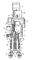
図1ないし図3において、符号1はねぎ収穫機で、機体2に、左右対をなしスピン(超信地)旋回を可能にしたクローラ3,3を装備している。機体2の一側ほぼ中央部にエンジン4を搭載し、その近傍に、図示しないがエンジン4により駆動される油圧装置を装備している。クローラ3,3間で、機体2の後部寄り下部位置に図示しないHST(油圧自動変速装置)を備えたトランスミッション5を設け、クローラ3,3を変速駆動するようにしている。
【0012】
上記クローラ3,3は、機体2の前進方向後部において駆動輪により履帯3bを駆動して走行するようにし、該履帯3bを接地側に押圧するようにして転接する複数の接地用転輪3cを支持する転輪フレーム3dを、機体2のフレームに対して前後一対のリンク部材により上下移動可能に支持し、上記転輪フレーム3dと機体2のフレームとの間に伸縮可能のシリンダ機構を設け、該シリンダ機構の伸縮により履帯3bの接地部分を駆動輪3aを中心に上下移動可能に構成している。
【0013】
クローラ3,3間の機体2の下部前方から機体2の中央下部を通って機体2の後方に向け、先端に掘取り刃6を有し、この掘取り刃6に連続して該掘取り刃6により掘り取られたねぎの根部を縦姿勢に載置して揚上しながら搬送する無端バーコンベヤ7を有する掘取り・搬送コンベヤ装置8を斜設している。この掘取り・搬送コンベヤ装置8の上方に位置して、この掘取り・搬送コンベヤ装置8より長さが長く、掘取り刃6により圃場から掘取られたねぎの茎葉部を縦姿勢で挟持して搬送する,左右一対の第1の挟持搬送ベルト9を設けている。この第1の挟持搬送ベルト9の搬送終端部下側には、第1の挟持搬送ベルト9により搬送されたねぎを受け、その茎葉部を縦姿勢で挟持して搬送する過程で横姿勢に変換して排出する第2の挟持搬送ベルト10を配設している。
【0014】
上記掘取り・搬送コンベヤ装置8の後端部は、機体2に対して、軸を介して上下方向に回動可能に枢支され、掘取り・搬送コンベヤ装置8と機体2との間に介装された油圧シリンダ11の伸縮作動により掘取り・搬送コンベヤ装置8は軸を中心に上下に回動するようになっている。上記第1の挟持搬送ベルト9の前端部はリンクアーム12の先端部に枢支され、後端部がリンクアームを介して機体2に枢支されている。そして、上記油圧シリンダ11により掘取り・搬送コンベヤ装置8の基部が回動して先端側が上動するとき、これと連動してリンクアーム12により第1の挟持搬送ベルト9も後方に移動するようになっている。また、掘取り・搬送コンベヤ装置8の下側にはねぎの土を落とす土落しロ−タ13が配設され、この土落しロ−タ13の後方に、ねぎの根部の根をほぐし、また、土を取り除く土落しドラム14が設けられている。
【0015】
そして、油圧シリンダ11により掘取り・搬送コンベヤ装置8を上方に回動させると、これと連動してリンクアーム12により第1の挟持搬送ベルト9が後方に移動し、掘取り・搬送コンベヤ装置8と第1の挟持搬送ベルト9は接触することがない。リンクアーム12の先端部と第1の挟持搬送ベルト9の間には長穴が設けられ、この長穴に対するリンクアーム12の支持位置を調節することにより、第1の挟持搬送ベルト9の支持高さが調節される。
【0016】
第2の挟持搬送ベルト10は、その始端部でねぎの茎葉部を縦姿勢で挟持して搬送し、その搬送過程でねぎを縦姿勢から横姿勢側へ順次捻り状態にして斜め横姿勢(ほぼ45度)に姿勢変更し、搬送終端部から排出するようにしている。その排出位置下方には作業台を兼ね、ねぎを機体の幅方向に載置して搬送する送りベルト(搬送帯)15が設けられ、第2の挟持搬送ベルト10から排出されたねぎを作業者が調製し、根部及び葉部を切断するようにしている。第2の挟持搬送ベルト10の始端部一側上方には、第1の挟持搬送ベルト9及び第2の挟持搬送ベルト10により挟持搬送されるねぎの葉部を支持して搬送する葉部搬送ベルト16が、第2の挟持搬送ベルト10と同軸に設けられている。この葉部搬送ベルト16は、その姿勢が支持アームを中心に回動調節機構により調節可能である。
【0017】
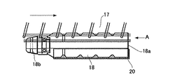
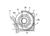
上記送りベルト15は、機体2の長さ方向に延びる無端ベルトからなり、このベルトのねぎの根部が載置される側縁に沿って、図4ないし図6に示す用に、相対向して内側に回転し、ねぎの根部を挟み込みながら移送する螺旋状の溝のあるスクリュードラム17及びこのスクリュードラム17より小径で長さの短い螺旋状の突起のあるスクリュー体18を設けている。スクリュー体18は、その始端側を回転軸19の軸端部により片持ち状態に軸支し、終端部18aを開放している。また、スクリュー体18には、該スクリュー体18と長さが同等かわずかに長いアンダーカバー20を設けている。さらに、スクリュー体18の前部には、該スクリュー体18より小径のガイドスクリュー18bを一体的に設けている。
【0018】
前記送りベルト15は、ねぎの根部を載置する側(図1及び図2で上側)を下に、葉部を載置する側を上にした姿勢で約20度の角度で傾斜している。また、この送りベルト15においては、第2の挟持搬送ベルト10の終端部から排出されたねぎに乱れがある場合は、作業者がベルトの幅方向に揃え、送りベルト15の後端部左右両側端の外側に設けた根部切断装置21により根部が切断される。根部切断装置21には、根部を送りベルト15との間で押さえる表面がスポンジになっている押さえベルト22と回転円盤からなるカッタ21aが設けられている。葉部切断装置23にも押さえベルト24が設けられている。この根部・葉部切断装置21,23に続いて排出ベルト25、選別台35、結束台36等が設けられている。
【0019】
上記押さえベルト22及びカッタ21aは、送りベルト15及びスクリュードラム17、スクリュー体18により送られてくるねぎの根部の根の生えている先端部分を切断するためのもので、根部切断用カッタ21aは高速に回転する。また、根部切断用カッタ21aは、送りベルト15の移動方向に対して外側に向け約3度傾斜して支持されており、ねぎの根部を送りベルト15の外側に向け切断する。この根部切断用カッタ21aは、送りベルト15の幅方向に移動調節可能であり、根部の切断深さを調節することができる。
【0020】
上記押さえベルト24及び葉部切断装置は、送りベルト15により送られてくるねぎの葉部を切断するためのもので、葉部切断用カッタは低速で回転する。葉部切断用カッタには、合成樹脂からなるガイド板が、葉部切断用カッタの側面に所定角度傾斜して接し、かつ搬送されてくるねぎの葉部を葉部切断用カッタの切断位置に案内するように設けられている(図示せず)。また、葉部切断用カッタ及びガイド板は、送りベルト15の幅方向に移動可能である。そして、葉部の切断長さが調節される。
【0021】
また、押さえベルト22,24は、カッタにより切断されるねぎの根部及び葉部より内側部分を押さえる位置に配設されている。さらに、押さえベルト22,24は、同じねぎに対して葉部側が根部側より押圧開始位置において先に押さえられ、押圧解除位置において根部側より先に開放され、根部側が押圧開始位置において葉部側より後に押さえられ、押圧解除位置において葉部側より後で開放されるよう、側面形状が舟形状に形成されている。また押さえベルト22と24は、押さえベルト22の方が押さえベルト24より幅が広く、十分な押圧力を有して根部を押圧して搬送して排出し、押さえベルト24においては葉部を痛めないように押圧力を小さくしている。
【0022】
上記エンジン4と反対側の機体2の側部には、操縦部26、操縦者用ステップ27、座席28、作業者用ステップ29、補助ステップ30等が設けられている。このうちの作業者用ステップ29には作業者が乗って作業するが、座席28に座った操縦者が作業することもできるように、座席28はその支持腕が、操縦者(作業者)が操縦部26に向かったり、あるいは送りベルト(作業台)15に向かったりすることができるように、自由に旋回可能になっている。また、座席28のシートは、操縦者(作業者)が座った状態で、あるいは立った状態で作業ができるように前後に起倒できる構造になっている。
【0023】
上記掘取り・搬送コンベヤ装置8の左右のフレームから前方に向けて、左右一対の支持アーム31,31が突出しており、この支持アーム31,31の先端に、収穫対象ねぎ畝の傾斜両肩部に転接する一対の接地ホィール32,32を対向させて軸支している。このホィール32,32は、掘取り・搬送コンベヤ装置8の上下調節と共に、収穫対象ねぎ畝の長さ方向に沿って機体の移動と共に追従する畝追従装置としての機能も果たすもので、掘取り・搬送コンベヤ装置8に対して上下調節シリンダ33により上下調節可能、かつ左右移動調節機構により左右移動調節可能に支持されている。また、一対のホィール32,32は、キャンバー角を有しており、収穫対象ねぎ畝の傾斜両肩部に接して回転し、機体を収穫対象ねぎ畝に追従して操向,移動させるようにしている。ホィール32と掘取り・搬送コンベヤ装置8の先端部との間に、収穫畝の肩部を崩すための畝崩しディスク34が支持アーム31に支持され、上下左右移動調節機構により上下左右移動調節可能に設けられている。
【0024】
上記エンジン4から動力を受けて変速するトランスミッション5においては、油圧無段変速装置(HST)により無段変速されるが、無段変速とトランスミッション5のギヤ変速とを組み合わせて無段または有段とに変速出力できるようにしている。そして、サイドクラッチ、デファレンシャル装置を介して動力伝達を接,断してクローラ3,3を無段または有段とに変速走行させ、またスピン旋回(超信地旋回)を可能にしている。また、トランスミッション5から、変速された動力が各作業部に伝達され、その回転速度が無段または有段とに変速調節可能であり、この変速とクローラ3,3の無段または有段走行と組合せることにより、掘取り作業速度が自在に設定可能である。
【0025】
上記操縦部26には、クローラ3,3の前進・中立・後進を切り換える主変速レバーが設けられている。この主変速レバーは、中立・後進側にシフトしたとき、そのシフト動作により送りベルト15、スクリュードラム17、スクリュー体18、押さえベルト22,24、カッタ21a、排出ベルト25の駆動を停止させるよう連動構成になっている。
【0026】
次に、上記のように構成された実施例のねぎ収穫機1の動作について説明する。ねぎ収穫機1は、ねぎを圃場から収穫するとき、クローラ3,3を収穫対象ねぎ畝の畝間に位置させ、接地ホィール32,32をねぎ畝の傾斜両肩部に転接させて、掘取り・搬送コンベヤ装置8の掘取り刃6部分を油圧シリンダ11により上下動調節して掘取り深さを調節し、機体の前進により畝崩しディスク34により畝を崩し、ねぎを畝土と共に下方から掘取り刃6により掘り上げ、その根部をバーコンベヤ7上に載置して根茎部に付着している土を落下させながら機体斜め上方に向け搬送する。この搬送と同時にねぎの茎葉部は第1の挟持搬送ベルト9に挟持されて傷つくことなく搬送される。クローラ3,3が走行する畝間に左右の傾きがあるときは、クローラ3,3の一方を上下調節して機体を水平状態に保持して走行させる。
【0027】
バーコンベヤ7及び第1の挟持搬送ベルト9により縦姿勢で搬送されるねぎがバーコンベヤ7の終端部に達したとき、土落しロ−タ13がねぎの根茎部に転接して、根茎部に付着している土が落とされる。ねぎがさらに移動すると、根部の根が土落しドラム14によりほぐされ一部の根が切られ、また残っている土がさらに除去される。そして、ねぎが第1の挟持搬送ベルト9の終端から排出される直前に、茎葉部が第2の挟持搬送ベルト10により挟持されて継送され、その葉部は葉部搬送ベルト16により搬送されて、第2の挟持搬送ベルト10の終端部において横姿勢となって送りベルト15上に排出される。
【0028】
送りベルト15上に排出されたねぎは、作業者用ステップ29に立った作業者、あるいは座席28に座った(あるいは座席28位置に立った)操縦者(作業者)により、排出されたねぎに乱れがある場合は根を揃え、根はスクリュードラム17、スクリュー体18間に引き込まれて移送され、押さえベルト22,24及びカッタ21aに向け移動し、根部及び葉部が切断される。そして、排出ベルト25により選別台35にほぼ所定量まとめられ、結束台36において結束される。もちろん、選別台35や結束台36のねぎを袋詰めし、あるいはコンテナに収容するようにしてもよい。ねぎ収穫機1の走行(あるいは作業)を停止するか、後退させるために主変速レバーを中立・後進側にシフトすると、送りベルト15、スクリュードラム17、スクリュー体18、押さえベルト22,24、カッタ21a、排出ベルト25への動力伝達が停止され、安全となる。
【0029】
ここで、ねぎ収穫機1は、クローラ3,3の無段または有段変速走行と、各回転部分の無段または有段変速回転とにより、圃場条件、作物条件に応じて適切な移動速度及び回転速度を選択でき、作業精度が高く、かつ能率のよい収穫作業が行われる。また、クローラ3,3はスピン旋回(超信地旋回)が可能であり、油圧シリンダ11により掘取り・搬送コンベヤ装置8、第1の挟持搬送ベルト9、第2の挟持搬送ベルト10、葉部搬送ベルト16、及び接地ホィール32、畝崩しディスク34等を上方に回動させ、機体2の全長を短くして枕地等において安定よくスピン旋回して1回の旋回で次の収穫畝に移動することができる。
【0030】
さらに、掘取り・搬送コンベヤ装置8の前方には、収穫対象ねぎ畝の長さ方向に沿って機体の移動と共に追従する接地ホィール32,32を設け、掘取り・搬送コンベヤ装置8に対し上下調節シリンダ33により上下調節可能、かつ左右移動調節機構により左右移動調節可能に支持しているので、両ホィール32は収穫対象のねぎ畝に対し正確に追従して機体を自動操向し、掘取り・搬送コンベヤ装置8及び第1の挟持搬送ベルト9、第2の挟持搬送ベルト10による自動掘取り・搬送が行われる。従って、操縦者は収穫対象ねぎ畝の畝端における機体操向操作以外は、ほとんどの時間をねぎの調製作業に当てることができる。
【0031】
【発明の効果】
以上説明したように、本発明のねぎ収穫機における根部移送装置によれば、以下の効果を奏することができる。
【0032】
▲1▼.搬送装置に、ねぎを機体の幅方向に載置して搬送する搬送帯と、該搬送帯のねぎの根部側が搬送される側の側端部に沿って、相対向して内側に回転し、ねぎの根部を挟み込みながら移送する一対のスクリュー体とを設け、この一対のスクリュー体は、径及び長さがそれぞれ異なり、そのうちの小径で長さの短いスクリュー体を、始端側を片持ち状態で軸支し、終端部を開放したので、搬送帯の幅方向に載置されて搬送されるねぎは、その根部が、相対向して内側に回転する一対のスクリュー体間に挟み込まれて移送され、根部切断装置のカッタに向けて放出されてカッタにより精度良く適正位置で切断することができる。このとき、一対のスクリュー体のうちの小径で長さの短いスクリュー体は、始端側が片持ち状態で軸支され、終端部が開放されていることで土や根がスクリュー体に詰まることがなく、スクリュー体の駆動力を低減させ、スクリュー体の耐久性を向上させることができる。
【0033】
▲2▼.小径で長さの短いスクリュー体に、該スクリュー体と長さが同等かわずかに長いアンダーカバーを設けたので、小径で長さの短いスクリュー体においては、アンダーカバーとの間にねぎの根を導入して、他のスクリュー体との間で根を挟み込みながら確実に移送することができる。
▲3▼.小径で長さの短いスクリュー体の前部に、該スクリュー体より小径のガイドスクリューを一体的に設けたので、搬送帯に載置されて搬送されてきたねぎの根は、小径で長さの短いスクリュー体の前部のガイドスクリューにより案内されて、他のスクリュー体との間に導入され、両スクリュー間に挟み込まれて移送され、根部を精度良く切除することができる。
【図面の簡単な説明】
【図1】本発明によるねぎ収穫機の全体平面図である。
【図2】同要部を切り欠いたねぎ収穫機の全体平面図である。
【図3】同ねぎ収穫機の全体側面図である。
【図4】要部の平面図である。
【図5】要部の断面図である。
【図6】図5のA方向からの端面図である。
【符号の説明】
1 ねぎ収穫機
2 機体
3 クローラ 3a 駆動輪 3b 履帯 3c 接地用転輪
3d 転輪フレーム
4 エンジン
5 トランスミッション
6 掘取り刃
7 無端バーコンベヤ
8 掘取り・搬送コンベヤ装置
9 第1の挟持搬送ベルト
10 第2の挟持搬送ベルト
11 油圧シリンダ
12 リンクアーム
13 土落しロ−タ
14 土落しドラム
15 送りベルト(搬送帯)
16 葉部搬送ベルト
17 スクリュードラム
18 スクリュー体 18a 終端部 18b ガイドスクリュー
19 回転軸
20 アンダーカバー
21 根部切断装置 21a 根部切断用カッタ
22,24 押さえベルト
23 葉部切断装置
25 排出ベルト
26 操縦部
27 操縦者用ステップ
28 座席
29 作業者用ステップ
30 補助ステップ
31 車輪支持アーム
32 接地ホィール
33 上下調節シリンダ
34 畝崩しディスク
35 選別台
36 結束台[0001]
BACKGROUND OF THE INVENTION
The present invention relates to a root transfer device in a leek harvester in which a root is sandwiched and moved by a pair of screw bodies and is cut by a cutter in the process of transporting a leek dug from a farm field.
[0002]
[Prior art]
Conventionally, a digging device that digs up the green onions cultivated in the field, a conveying device that conveys the digged green onion toward the rear of the aircraft, and a leek conveyed by the conveying device. The present applicant has proposed a green onion harvester including a root / leaf cutting device for cutting the root and the leaf, and a storage device for preparing and storing the transferred green onion. In addition to the leek harvester, a leek preparation device has also been proposed that cuts and prepares roots and leaves from leek dug from the field. Furthermore, in order to improve and stabilize the root cutting accuracy by aligning the roots of the green onion with respect to the transfer device and the root / leaf cutting device, the transfer device rotates inward and faces each other while sandwiching the root of the green onion. A green onion harvesting machine provided with a pair of screw bodies to be transferred together has been proposed.
[0003]
[Problems to be solved by the invention]
The pair of screw bodies that transfer while sandwiching the root part of the conventional green onion are supported by the support portions at both ends of both screw bodies, so that the soil and the root of the green onion are attached to the rear side in the moving direction. There is a problem that it accumulates on the support part of the slag and causes clogging. In addition, the roots of the soil and green onion are accumulated in the support portion on the front side of the screw onion in the moving direction, and the root of the moving green onion is not smoothly sandwiched between the pair of screw bodies and the root is not aligned. There was also.
[0004]
Therefore, in order to solve the above problems, the present invention supports a screw body of a small diameter and a short length of the pair of screw bodies in a cantilevered state at the start end side, opens the end portion, and underlines. Root transport in a leek harvester with a cover and a small-diameter guide screw at the front to eliminate clogging of soil and green onion roots, aligning the roots of green onions and removing the roots with a cutting device with high accuracy An object is to provide an apparatus.
[0005]
[Means for Solving the Problems]
In order to achieve the above object, the present invention has the following configuration.
[0006]
A. A digging device that digs the green onions that are vegetated in the field, a conveying device that conveys the digged green onion toward the rear of the aircraft in a predetermined posture, a root from the green onion conveyed by the conveying device, and A green onion harvester equipped with a root / leaf cutting device for cutting leaves,
A conveying band for transferring green onions in the width direction of the machine body and conveying the green onions to the conveying device, and a side end portion on the side where the green onions side of the conveying band is conveyed rotate opposite to each other. A pair of screw bodies that transfer while sandwiching the root part of the green onion, the pair of screw bodies are different in diameter and length, and the screw body having a small diameter and a short length is cantilevered on the start end side The end was opened with a shaft.
[0007]
B. An under cover having a length equal to or slightly longer than that of the screw body was provided on the screw body having a small diameter and a short length.
C. A guide screw having a smaller diameter than that of the screw body is integrally provided at a front portion of the screw body having a small diameter and a short length.
[0008]
[Action]
A. above. ~ C. By having the configuration of (Claims 1 to 3), the root transfer device in the leek harvester of the present invention performs the following actions.
[0009]
(1). A. above. With this configuration, the green onions that are mounted and transported in the width direction of the transport band are transported with their roots sandwiched between a pair of screw bodies that rotate inward and facing each other, and are transferred to the cutter of the root cutting device. It is discharged toward and cut with high accuracy by the cutter. At this time, the screw body with a small diameter and a short length of the pair of screw bodies is pivotally supported in a cantilevered state at the start end side, and the soil and roots are not clogged by the open end portion. .
[0010]
(2). B. above. With this configuration, in a screw body with a small diameter and a short length, a green onion root is introduced between the undercover and the screw body is transferred while sandwiching the root with another screw body.
(3). C. above. With the structure, the root of the green onion that has been placed and transported on the transport belt is guided by the guide screw at the front of the screw body with a small diameter and a short length, and is introduced between the other screw bodies, It is sandwiched between both screws and transferred.
[0011]
DETAILED DESCRIPTION OF THE INVENTION
Hereinafter, an embodiment of the present invention will be described in detail with reference to the accompanying drawings.
1 to 3, reference numeral 1 denotes a leek harvesting machine, and a
[0012]
The
[0013]
It has a digging blade 6 at the tip from the lower front of the
[0014]
The rear end portion of the digging / conveying conveyor device 8 is pivotally supported with respect to the
[0015]
When the digging / conveying conveyor device 8 is rotated upward by the
[0016]
The second sandwiching and transporting
[0017]
The
[0018]
The
[0019]
The
[0020]
The holding
[0021]
The
[0022]
On the side of the
[0023]
A pair of left and
[0024]
In the transmission 5 that receives power from the engine 4 and shifts, it is continuously variable by a hydraulic continuously variable transmission (HST). The continuously variable transmission and the gear shift of the transmission 5 are combined to be continuously variable or stepless. The gears can be output at different speeds. Then, the power transmission is connected and disconnected via the side clutch and the differential device, and the
[0025]
The
[0026]
Next, operation | movement of the leek harvesting machine 1 of the Example comprised as mentioned above is demonstrated. When the green onion harvester 1 harvests green onions from the field, the
[0027]
When the green onion conveyed in the vertical position by the bar conveyor 7 and the first sandwiching and conveying belt 9 reaches the terminal end of the bar conveyor 7, the earth-carrying
[0028]
The green onions discharged on the
[0029]
Here, the leek harvesting machine 1 has an appropriate moving speed according to the field condition and the crop condition by the stepless or stepped variable speed travel of the
[0030]
Further, in front of the digging / conveying conveyor device 8, grounding
[0031]
【The invention's effect】
As described above, according to the root transfer device of the leek harvesting machine of the present invention, the following effects can be obtained.
[0032]
(1). A conveying belt that carries green onions in the width direction of the machine body and conveys them to the conveying device, and a root end side of the green onions of the conveying belt is rotated inward and opposite to each other along the side end of the conveying belt. A pair of screw bodies that are transported while sandwiching the root of the green onion, and the pair of screw bodies are different in diameter and length, of which a small diameter and short length screw body is cantilevered at the start end side. Since the shaft is supported and the terminal end is opened, the green onion that is placed and transported in the width direction of the transport belt is transported with its root portion sandwiched between a pair of screw bodies that rotate inward in opposition to each other. It is discharged toward the cutter of the root cutting device and can be cut at an appropriate position with high accuracy by the cutter. At this time, the screw body having a small diameter and a short length of the pair of screw bodies is supported by the start end side in a cantilever state, and the end portion is opened so that the soil and roots are not clogged by the screw body. The driving force of the screw body can be reduced and the durability of the screw body can be improved.
[0033]
(2). Since a small-diameter and short-length screw body is provided with an undercover that is the same length or slightly longer than the screw body, in a small-diameter and short-length screw body, the green onion root is placed between the undercover and the undercover. It can introduce | transduce and can convey reliably, pinching a root between other screw bodies.
(3). Since a guide screw having a smaller diameter than that of the screw body is integrally provided at the front portion of the screw body having a small diameter and a short length, the root of the green onion that has been transported by being placed on the transport belt has a small diameter and a length. It is guided by the guide screw at the front of the short screw body, introduced between the other screw bodies, sandwiched between the two screws, transferred, and the root portion can be excised with high accuracy.
[Brief description of the drawings]
1 is an overall plan view of a leek harvester according to the present invention.
FIG. 2 is an overall plan view of a leek harvester with the main part cut away.
FIG. 3 is an overall side view of the same leek harvesting machine.
FIG. 4 is a plan view of a main part.
FIG. 5 is a cross-sectional view of a main part.
6 is an end view from the direction A in FIG. 5;
[Explanation of symbols]
DESCRIPTION OF SYMBOLS 1
16
Claims (3)
上記搬送装置に、ねぎを機体の幅方向に載置して搬送する搬送帯と、該搬送帯のねぎの根部側が搬送される側の側端部に沿って、相対向して内側に回転し、ねぎの根部を挟み込みながら移送する一対のスクリュー体とを設け、この一対のスクリュー体は、径及び長さがそれぞれ異なり、そのうちの小径で長さの短いスクリュー体を、始端側を片持ち状態で軸支し、終端部を開放したことを特徴とするねぎ収穫機における根部移送装置。A digging device that digs the green onions cultivated in the field into the traveling machine, a conveying device that conveys the digged green onion toward the rear of the aircraft in a predetermined posture, and a root portion from the green onion conveyed by the conveying device; A green onion harvester equipped with a root and leaf cutting device for cutting leaves,
A conveying band for transferring green onions in the width direction of the machine body to the conveying device and a side end of the conveying band on the side where the green onions are conveyed are opposed to each other and rotated inward. A pair of screw bodies that transfer while sandwiching the root part of the green onion, and the pair of screw bodies have different diameters and lengths, of which the screw body has a small diameter and a short length, and the starting end side is cantilevered A root transfer device in a leek harvesting machine, characterized in that it is pivotally supported by and the end portion is opened.
Priority Applications (1)
| Application Number | Priority Date | Filing Date | Title |
|---|---|---|---|
| JP2001334580A JP3771480B2 (en) | 2001-10-31 | 2001-10-31 | Root transfer device for green onion harvester |
Applications Claiming Priority (1)
| Application Number | Priority Date | Filing Date | Title |
|---|---|---|---|
| JP2001334580A JP3771480B2 (en) | 2001-10-31 | 2001-10-31 | Root transfer device for green onion harvester |
Publications (3)
| Publication Number | Publication Date |
|---|---|
| JP2003134914A JP2003134914A (en) | 2003-05-13 |
| JP2003134914A5 JP2003134914A5 (en) | 2005-06-02 |
| JP3771480B2 true JP3771480B2 (en) | 2006-04-26 |
Family
ID=19149686
Family Applications (1)
| Application Number | Title | Priority Date | Filing Date |
|---|---|---|---|
| JP2001334580A Expired - Fee Related JP3771480B2 (en) | 2001-10-31 | 2001-10-31 | Root transfer device for green onion harvester |
Country Status (1)
| Country | Link |
|---|---|
| JP (1) | JP3771480B2 (en) |
-
2001
- 2001-10-31 JP JP2001334580A patent/JP3771480B2/en not_active Expired - Fee Related
Also Published As
| Publication number | Publication date |
|---|---|
| JP2003134914A (en) | 2003-05-13 |
Similar Documents
| Publication | Publication Date | Title |
|---|---|---|
| JP4531967B2 (en) | Aligning and conveying device in leek harvesting machine | |
| JP3868615B2 (en) | Green onion harvester | |
| JP4398659B2 (en) | Green onion harvester | |
| JP2005176784A (en) | Welsh onion conveyor | |
| JP3443203B2 (en) | Agricultural harvester | |
| JP3771480B2 (en) | Root transfer device for green onion harvester | |
| JP3648532B2 (en) | Green onion harvester | |
| JPH10313634A (en) | Harvest carrying device in agricultural product harvester | |
| JP4515629B2 (en) | Structure for preventing reverse rotation of working section in agricultural product harvesting machine | |
| JP3803993B2 (en) | Green onion harvester | |
| JP2000316355A (en) | Ridge-breaking device of welsh onion harvester | |
| JP2000312521A (en) | Soil removing drum for welsh onion harvester | |
| JP2003310021A (en) | Cut leaf-dropping position-changing device of welsh onion harvester | |
| JP3455342B2 (en) | Agricultural harvester | |
| JP3633703B2 (en) | Green onion harvester | |
| JP2000316352A (en) | Welsh onion harvester | |
| JP3662726B2 (en) | Self-propelled root vegetable harvester | |
| JP4365933B2 (en) | Green onion harvester | |
| JP3334832B2 (en) | Agricultural harvester | |
| JP2003047310A (en) | Apparatus for cutting root part and leaf part in welsh onion harvester | |
| JP3305795B2 (en) | Head vegetable harvester | |
| JP2782301B2 (en) | Head vegetable harvester | |
| JP3290232B2 (en) | Head vegetable harvester | |
| JP4523701B2 (en) | Produce harvester | |
| JP3414546B2 (en) | Agricultural harvester |
Legal Events
| Date | Code | Title | Description |
|---|---|---|---|
| A521 | Written amendment |
Free format text: JAPANESE INTERMEDIATE CODE: A523 Effective date: 20040811 |
|
| A621 | Written request for application examination |
Free format text: JAPANESE INTERMEDIATE CODE: A621 Effective date: 20040811 |
|
| A977 | Report on retrieval |
Free format text: JAPANESE INTERMEDIATE CODE: A971007 Effective date: 20060201 |
|
| TRDD | Decision of grant or rejection written | ||
| A01 | Written decision to grant a patent or to grant a registration (utility model) |
Free format text: JAPANESE INTERMEDIATE CODE: A01 Effective date: 20060207 |
|
| A61 | First payment of annual fees (during grant procedure) |
Free format text: JAPANESE INTERMEDIATE CODE: A61 Effective date: 20060209 |
|
| R150 | Certificate of patent or registration of utility model |
Free format text: JAPANESE INTERMEDIATE CODE: R150 |
|
| FPAY | Renewal fee payment (event date is renewal date of database) |
Free format text: PAYMENT UNTIL: 20120217 Year of fee payment: 6 |
|
| FPAY | Renewal fee payment (event date is renewal date of database) |
Free format text: PAYMENT UNTIL: 20150217 Year of fee payment: 9 |
|
| RD03 | Notification of appointment of power of attorney |
Free format text: JAPANESE INTERMEDIATE CODE: R3D03 |
|
| R250 | Receipt of annual fees |
Free format text: JAPANESE INTERMEDIATE CODE: R250 |
|
| LAPS | Cancellation because of no payment of annual fees |