JP3662726B2 - Self-propelled root vegetable harvester - Google Patents
Self-propelled root vegetable harvester Download PDFInfo
- Publication number
- JP3662726B2 JP3662726B2 JP27771197A JP27771197A JP3662726B2 JP 3662726 B2 JP3662726 B2 JP 3662726B2 JP 27771197 A JP27771197 A JP 27771197A JP 27771197 A JP27771197 A JP 27771197A JP 3662726 B2 JP3662726 B2 JP 3662726B2
- Authority
- JP
- Japan
- Prior art keywords
- conveyor
- root
- feed roller
- gear box
- root vegetables
- Prior art date
- Legal status (The legal status is an assumption and is not a legal conclusion. Google has not performed a legal analysis and makes no representation as to the accuracy of the status listed.)
- Expired - Fee Related
Links
Images


Landscapes
- Harvesting Machines For Root Crops (AREA)
Description
【0001】
【発明の属する技術分野】
本発明は、根菜類、特に、人参を収穫する自走式根菜収穫機において、下部コンベア上に設けられた横送りローラーの構成に関するものである。
【0002】
【従来の技術】
従来から、大根や人参等を収穫する自走式根菜収穫機は公知となっており、走行装置上部の左右一側に運転席を配置し、他側に進行方向と平行に引抜きコンベアを配置し、この引抜きコンベアの前部に鍬状のサブソイラからなる掘起し装置を配置して、この掘起し装置を土中に挿入して、下方より根菜を土中より掘り起こし、引抜きコンベアのベルトにて根菜の葉部分を両側より挟持して斜め上方に搬送しながら引抜き、搬送部後端にカッターを配置して、該カッターにより根菜の葉の根元部を切断し、下部コンベアに落下した根菜を、選別コンベアに受渡し、該選別コンベアにより選別後の根菜を収納容器に収納するように構成されている。この従来の構成においては、前記下部コンベアの中途部上に斜め方向に横送りローラーを配設し、該横送りローラーの回転と下部コンベアの搬送駆動によって、根菜が側部の選別コンベア上に落下するようにしていた。
【0003】
【発明が解決しようとする課題】
しかし、前述の横送りローラーは斜め方向に固定されており、特に、冬人参を収穫する場合には、その冬人参は茎葉が短く、そして、しっかりしているために切断装置によって十分切断されないことがあり、斜めローラーの終端部で引っ掛かり、詰まる場合があって、選別コンベア上に落下させることができないという不具合があったのである。
【0004】
【課題を解決するための手段】
本発明の解決しようとする課題は以上の如くであり、次に該課題を解決する為の手段を説明する。
走行機体の左右一側で根菜を掘り起こし、後方に搬送して、根菜の葉部切断後の根部を、後方へ水平方向に配置された下部コンベア48に載置して、該下部コンベア48の中途部上に斜め方向に配設した横送りローラー49により、下部コンベア48側方に配置した選別コンベア50へ根菜を搬送するようにした自走式根菜収穫機において、該下部コンベア48の左側方に、下部ギアボックッス52を配設し、該下部ギアボックッス52に、上部ギアボックッス51を伝動軸55を中心に左右水平方向に回転自在に支持し、該上部ギ アボックッス51に横送りローラー49の駆動軸49aの一端を回転自在に支持し、該駆動軸49aの端部及び伝動軸55の上端にはそれぞれベベルギアを固定して動力を伝達し、前記横送りローラー49の前端側を、水平面で前記上部ギアボックッス51を中心に回動可能に支持し、該横送りローラー49の後端側を、斜め方向の使用時の位置と、進行方向に平行な収納位置に固定可能としたものである。
【0005】
【発明の実施の形態】
本発明の実施の形態を説明する。
図1は自走式根菜収穫機の側面図、図2は同じく平面図、図3は本発明の横送りローラーを回動可能に構成したことを示す図、図4は同じく動力の伝達を示す側面図、図5は下部コンベアと選別コンベアの配設位置を示す平面図、図6は排土板を設けた際の側面図、図7は同じく平面図、図8は選別コンベアの左端部を下部コンベアの下方全幅内に配置した際の後面図、図9は選別コンベアに弾性体の突起を設けた際の後面図、図10は選別コンベアに設けた弾性体の突起を平面視櫛状に構成した際の平面断面図である。
【0006】
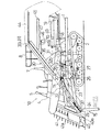
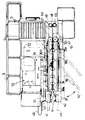
図1、図2より自走式根菜収穫機、特に人参収穫を主目的とする根菜収穫機の全体構成について説明する。
まず、水平状に配置したメインフレーム1の下方にクローラ式走行装置2が配設されており、メインフレーム1の右(進行方向に向かって右側)前上に運転操作部10が配設されている。運転操作部10は前部にフロントコラム4を立設し、その上部に操向と掘起し装置15の昇降操作を同時に行える操作レバー5が突設され、側部にアクセルレバーが配設されている。このフロントコラム4の側部にサイドコラム3が立設され、このサイドコラム3上に作業レバーや副変速レバー等の各操作レバーが突出されている。前記フロントコラム4の後方に運転座席7が配設され、その下後方にエンジン室が配設されて、このエンジン室内にエンジン12が内蔵されていて、エンジン12はエンジンカバー6によって覆われている。該エンジンカバー6の上部にコンテナ台8が載置されている。
【0007】
そして、走行機体の左側に根菜を堀取り、後方へ搬送し、葉部分を切除する機構と、その後部に根部をコンテナ9に収容する機構が配設されている。つまり、メインフレーム1左側前部より、引起し装置40、引抜きコンベア30の高さを設定するゲージ輪43、根菜の葉部分を引き上げる引上げ装置41、その下方に土中の根菜を堀り上げるための掘起し装置15、引起し装置40の後部より、掘り上げた根菜の葉部の両側を挟持搬送する引抜きコンベア30、引抜きコンベア30の後方にカッター47、その下方に下部コンベア48と横送りローラー49、その側方のコンテナへ搬送する選別コンベア50が配置されている。
【0008】
この一連の根菜収穫装置の各装置について具体的に説明する。
まず、掘起し装置15は、前記メインフレーム1の前端の上部と下部に回動支点軸20・21が横設されており、この回動支点軸20・21に上リンク22と下リンク23の後部がそれぞれ枢支され、上リンク22と下リンク23の前部がブラケット25と枢結されている。この上リンク22と下リンク23が平行リンクを形成し、このブラケット25にサブソイラ24の上端が固定されている。
【0009】
前記下リンク23の後端には、アーム26を介して油圧シリンダーからなる昇降シリンダー27と連結されて、この昇降シリンダー27を作動させることによって昇降可能としている。前記上リンク22の前部には偏心カムを介してサブソイラ24の上部が支持され、該偏心カムを回動させてサブソイラ24を振動駆動できるようにし、根菜の下方より土中を振動して、根菜を浮き上がらせ、引抜きが容易にできるようにしている。
【0010】
そして、前記引起きコンベア30の後部がコンベア支持フレーム31に支持され、該コンベア支持フレーム31がメインフレーム1・1より上方へ突出した支持体32に支持されている。該支持体32は、左右回動軸32aと上下回動筒32bより構成される一体構成部材である。前記引抜きコンベア30は掘起し装置15の昇降を利用して、上下回動筒32bを中心にして上下に回動して、引抜き高さを変更したり、持ち上げたりできるようにしている。また、図2の二点鎖線(30’)で示すように、前記左右回動軸32aを中心に回動して、動力伝達機構11を開放することができる。
【0011】
前記引抜きコンベア30は、搬送フレーム30L・30Rを前後方向平行に、前低後高に傾斜して配置し、搬送フレーム30L・30Rの後部下面が前記コンベア支持フレーム31によって支持され、この搬送フレーム30L・30Rの前後両端にプーリー33・33を配置し、その中途部にガイドプーリー34・34・・・を配し、これらプーリーに搬送ベルト30a・30aを巻回し、引抜きコンベア30の中途部から後部の下面には、左右一対の搬送ベルトを巻回した補助搬送コンベア36が設けられ、葉部の根菜側を保持している。また、引抜きコンベア30前端上部にスターホイル37・37が配設されて、根菜の葉部を掻き込んでいる。
【0012】
また、図6、図7に示すように、搬送フレーム30Lの左外側に、平面視略L字型の支持部材80の上端側を固定し、また、搬送フレーム30Rの右外側には平面視略L字型の支持部材81の上端側を固定し、該支持部材80・81の下端側に、排土板82を固定し、該排土板82を左右方向に傾斜させて配置している。前記排土板82は、搬送ベルト30a・30aによって挟持できずに堀り残したり、途中まで引き上げた根菜や、途中で落下した根菜を、土ごとクローラー2・2の間に移動させるものである。従って、その堀り残した根菜はクローラー2・2によって踏みつけられることがなく、クローラーで鎮圧されないので、人力で根菜を掘り出す必要がなく、回収する作業は容易に行うことができ、作業能率を向上できるのである。
また、前述のように、引抜きコンベア30は掘起し装置15の昇降を利用して、上下回動筒32bを中心にして上下に回動できるようにしているので、搬送フレーム30L・30Rを回動すると、それに支持された排土板82も上下に回動でき、高さ調節もできるのである。
【0013】
そして、引抜きコンベア30の前端部よりアームを前方に突出して、引起し装置40を上下高さ調整可能に固設している。この引起し装置40はタイン40a・40a・・・を突出したベルトを上下方向に対向して巻回し、根菜の葉部を中央上方へ引き上げるようにしている。そして、前記引起し装置40より前方に連結体を前方に突出して引上げ装置41を固設している。該引上げ装置41は引起し装置40と同様にタイン41a・41a・・・を突出したベルトを前後面で上下方向に左右に配置して、収穫条の左右両側から葉部を引き上げるようにしている。
【0014】
そして、前記引起し装置40より前側方にゲージ輪43が配置されている。このゲージ輪43は、前記引起し装置40の側方に突出する支持アーム42の先端に回転自在に支持され、該ゲージ輪43を支持アーム42に上下高さ調整可能にすることで、引起し装置40及び引上げ装置41からなる前処理装置と、引抜きコンベア30の高さを調節することができ、根菜の葉部の挟持位置が調節できる。
【0015】
そして、前記引抜きコンベア30、補助搬送コンベア36の後部には葉部排出コンベア44を前後方向水平に後方へ延設されている。前記補助搬送コンベア36の中途部には、水平コンベア45を前後方向水平に後方に延出されており、該水平コンベア45の下方には根菜を案内するガイド46を配設しており、該ガイド46と水平コンベア45の間において、カッター47を配置している。補助搬送コンベア36により搬送された根菜の葉部は、前記水平コンベア45に引き継がれ、根菜の根部上端が位置決めされながら後方へ搬送され、葉部が所定の位置でカッター47によって切断され、根部はその下方に配設された弾性体で構成した衝撃吸収板70へ一旦落下し、その後に該衝撃吸収板70の下方に配設された下部コンベア48上に滑り落とされ、葉部は前記葉部排出コンベア44に搬送されて後方から圃場面に落下される。
【0016】
そして、下部コンベア48は幅広のベルトコンベアからなり、補助搬送コンベア36の後部下方から後方に水平方向に配置されて、この下部コンベア48の中途部上に斜め方向に、後述する横送りローラー49が配設されている。横送りローラー49の回転と下部コンベア48の搬送駆動によって、根菜が側部の選別コンベア50上に落下するようにしている。該選別コンベア50は、本機後部で左右方向に配設されて幅広のローラーコンベアよりなり、側方へ送りながら根菜に付着した土を落とすようにしている。この選別コンベア50の終端下方にはコンテナ載置台54が配置され、このコンテナ載置台54はコンテナ9を載置している。
【0017】
また、この自走式根菜収穫機の前記引抜きコンベア30の前端部下方には、肩揃えガイド71と根菜の根部を切断する尻尾切り装置61を配設している。前記肩揃えガイド71は、引抜きコンベア30の傾斜角度より緩く前低後高に配設して、前記引抜きコンベア30によって搬送される根菜の根部上部の高さを揃えるものである。前記尻尾切り装置61は、肩揃えガイド71の後方下方に配設し、根菜の尾部を案内する案内ガード62と尻尾を切断する切断部63及び、切断部63を支持する支持杆14により構成されている。前記切断部63は、駆動ケースと該駆動ケースに回動自在に枢支される左右一対のディスクカッター13・13により構成されている。
【0018】
前記切断部63の前方には案内ガード62を配設している。該案内ガード62により、引抜きコンベア30により葉部が挟持されて搬送される根菜の尾部が、ディスクカッター13・13に案内され切断されるのである。また、切断部63の下方には、上面の開口する箱体を載置している。該箱体は栽培の不揃いによって生じる挟持に失敗した根菜や極小の根菜等を受ける様にしている。
【0019】
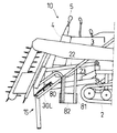
次に前記横送りローラー49について説明する。
図3、図4に示すように、下部コンベア48の左側方に下部ギアボックッス52が配設され、該下部ギアボックッス52に伝動軸53が水平方向に、伝動軸55が鉛直方向にそれぞれ支持され、該伝動軸53と伝動軸55はベベルギアを介して動力が伝達される構成としている。前記下部ギアボックッス52上には上部ギアボックッス51が前記伝動軸55を中心に左右回転自在に支持され、該上部ギアボックッス51に横送りローラー49の駆動軸49aの一端が回転自在に支持され、該駆動軸49aの端部及び伝動軸55の上端にはそれぞれベベルギアを固定して動力を伝達するようにしている。
【0020】
そして、前記横送りローラー49の駆動軸49aの他端は支持プレート70に回転自在に支持され、該支持プレート70は、図3における斜めに位置した状態と二点鎖線で示す収納状態に、本体側へボルトやピン等で固定するようにしている。但し、シリンダーのピストンロッドを支持プレート70と連結してスイッチ操作等で斜め位置と収納位置またはその中間位置等に変更できるようにすることも可能である。
【0021】
このような構成において、前記エンジンの出力軸からクラッチやプーリーやベルト等を介して伝動軸53に動力が伝えられる。該伝動軸53よりベベルギアを介して伝動軸55に伝え、更にベベルギアを介して駆動軸49aに動力を伝えて、横送りローラー49を回転するように構成している。そして、該横送りローラー49の回転と下部コンベア48の搬送駆動によって、根菜を側部の選別コンベア50上に落下するようにしている。
【0022】
そして、茎葉が短くしっかりとした冬人参収穫時には、その茎葉が切断されずに、または、茎葉が残って搬送される場合があり、その冬人参は横送りローラー49に搬送されると引っ掛かってしまうことがあり、引っ掛かると選別コンベア50に落下搬送させることができなくなり、詰まりが生じてしまう。このような不具合が発生しないように、本発明では図3に示すように、前記横送りローラー49を伝動軸55を中心に左方向へ回動させ、進行方向と平行となる位置とした収納位置とすることにより、下部コンベア48によって搬送される冬人参は、選別コンベア50上に落下させずに機体後方に排出され、この排出位置にコンテナを配置することで、人参を収穫するのである。
【0023】
こうして冬人参を収穫すると、残った茎葉の切断作業は人力で行うこととなるが、横送りローラー49を使用しないので、引っ掛かることがなく、収穫作業を中断することはないのである。つまり、その根菜収穫機によって冬人参を掘り出すだけの作業となるが、掘り出し作業を人力で行うことは重労働であるので、斜めローラー49で詰まって根菜収穫機を使用しないで人力で収穫するよりは、作業の軽減効果は大きいのである。
【0024】
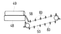
また、図5に示すように、前記選別コンベア50の後端側を、横送りローラー49の終端側よりも後方に配置することができ、該横送りローラー49の回転と下部コンベア48の搬送駆動によって搬送されてくる根菜を、側部の選別コンベア50の全幅50aを使用して搬送する構成とすることができる。
つまり、図2のように、選別コンベア50の後端と下部コンベア48の後端が略同一線上に位置すると、横送りローラー49によって人参が搬送されると、選別コンベア50の後部側にかたまって搬送されることになり、選別しにくいのである。
従って、選別コンベア50の後端側を、横送りローラー49の終端側よりも後方に配置することで、選別コンベア50の全幅を使用して搬送することができ、根菜同志の干渉による損傷が少なくなると共に、損傷品を見つけ易く、手選別作業が容易となるのである。また、作業速度が向上する。
【0025】
また、従来のように下部コンベア48と選別コンベア50の始端側の上面を一致させていると、下部コンベア48の右側面と選別コンベア50の始端側のローラーの上面との間に窪み状のスペースができて、その窪みに根菜が落ちると搬送されなくなるのである。そこで、図8に示すように、前記選別コンベア50の左端部分を後面視で下部コンベア48の下方に配置すると共に、該選別コンベア50を左側に傾斜させる構成とすることで、下部コンベア48と選別コンベア50の間に根菜が詰まることを防止することができ、極小の根菜でも詰まり等による停滞がないために、根菜の搬送される流れが一定となり、手選別作業が行い易いのである。
【0026】
また、図9に示すように、前記選別コンベア50に樹脂等の弾性体の突起83・83・・・を設け、該突起83・83・・・によって、根菜を強制的に搬送するよう構成することができる。従って、根菜の停滞や詰まり等は発生せず、一定の搬送速度を保つことができるのである。また、前記突起83・83・・・は、樹脂等の弾性体より構成されており、収穫した根菜等に傷をつけることがないのである。
【0027】
また、前記選別コンベア50の突起83・83・・・を図10に示すように、平面視櫛状の弾性体とすることもでき、櫛83aと櫛83aの間に流し板58を嵌入して配置して、土の付いた根菜を搬送する際、櫛状の弾性体と流し板58との隙間より土を取り除くことができ、土が停滞し、付着することがないのである。
【0028】
【発明の効果】
本発明は以上のように構成したので、次のような効果を奏するのである。
走行機体の左右一側で根菜を掘り起こし、後方に搬送して、根菜の葉部切断後の根部を 、後方へ水平方向に配置された下部コンベア48に載置して、該下部コンベア48の中途部上に斜め方向に配設した横送りローラー49により、下部コンベア48側方に配置した選別コンベア50へ根菜を搬送するようにした自走式根菜収穫機において、該下部コンベア48の左側方に、下部ギアボックッス52を配設し、該下部ギアボックッス52に、上部ギアボックッス51を伝動軸55を中心に左右水平方向に回転自在に支持し、該上部ギアボックッス51に横送りローラー49の駆動軸49aの一端を回転自在に支持し、該駆動軸49aの端部及び伝動軸55の上端にはそれぞれベベルギアを固定して動力を伝達し、前記横送りローラー49の前端側を、水平面で前記上部ギアボックッス51を中心に回動可能に支持し、該横送りローラー49の後端側を、斜め方向の使用時の位置と、進行方向に平行な収納位置に固定可能としたので、根菜の葉茎部が残ったまま下部コンベアへ搬送されるようなときには、横送りローラーを進行方向と平行にして収納位置として使用せずに、機体後方で収穫するようにすることができて、根菜が横送りローラーで詰まることがなく、作業を連続して行うことができる。
また、葉茎部が確実に切断される場合には、横送りローラーを斜めに配置して選別コンベアへ送ることができ、根菜の種類により搬送方向を任意に変更できるようになったのである。
【0029】
そして、茎葉が短くしっかりとした冬人参収穫時には、その茎葉が切断されずに、または、茎葉が残って搬送される場合があり、その冬人参は横送りローラー49に搬送されると引っ掛かってしまうことがあり、引っ掛かると選別コンベア50に落下搬送させることができなくなり、詰まりが生じてしまう。
このような不具合が発生しないように、本発明では図3に示すように、前記横送りローラー49を伝動軸55を中心に左方向へ回動させ、進行方向と平行となる位置とした収納位置とすることにより、下部コンベア48によって搬送される冬人参は、選別コンベア50上に落下させずに機体後方に排出され、この排出位置にコンテナを配置することで、人参を収穫するのである。
こうして冬人参を収穫すると、残った茎葉の切断作業は人力で行うこととなるが、横送りローラー49を使用しないので、引っ掛かることがなく、収穫作業を中断することはないのである。
つまり、その根菜収穫機によって冬人参を掘り出すだけの作業となるが、掘り出し作業を人力で行うことは重労働であるので、斜めローラー49で詰まって根菜収穫機を使用しないで人力で収穫するよりは、作業の軽減効果は大きいのである。
【図面の簡単な説明】
【図1】 自走式根菜収穫機の側面図である。
【図2】 同じく平面図である。
【図3】 本発明の横送りローラーを左方向に回動可能に構成したことを示す図である。
【図4】 同じく動力の伝達を示す側面図である。
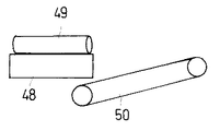
【図5】 下部コンベアと選別コンベアの配置位置を示す平面図である。
【図6】 排土板を設けた際の側面図である。
【図7】 同じく平面図である。
【図8】 選別コンベアの左端部を下部コンベアの下方全幅内に配置した際の後面図である。
【図9】 選別コンベアに弾性体の突起を設けた際の後面図である。
【図10】 選別コンベアに設けた弾性体の突起を平面視櫛状に構成した際の平面断面図である。
【符号の説明】
48 下部コンベア
49 横送りローラー
50 選別コンベア
51 上部ギアボックッス
52 下部ギアボックッス[0001]
BACKGROUND OF THE INVENTION
The present invention relates to a configuration of a transverse feed roller provided on a lower conveyor in a self-propelled root vegetable harvester that harvests root vegetables, particularly carrots.
[0002]
[Prior art]
Conventionally, a self-propelled root crop harvester that harvests radishes, carrots, etc. has been publicly known. , Digging device consisting of a bowl-shaped subsoiler is placed at the front of this pulling conveyor, this digging device is inserted into the soil, and root vegetables are dug up from the bottom to the belt of the pulling conveyor. Pull the root vegetable leaves from both sides and pull them out while transporting diagonally upward, place a cutter at the rear end of the transport section, cut the root part of the root vegetable leaves with the cutter, and drop the root vegetables on the lower conveyor Then, it is delivered to a sorting conveyor, and the sorted root vegetables are stored in a storage container by the sorting conveyor. In this conventional configuration, a transverse feed roller is disposed obliquely on the middle part of the lower conveyor, and the root vegetables fall on the side sorting conveyor by the rotation of the transverse feed roller and the conveyance drive of the lower conveyor. I was trying to do it.
[0003]
[Problems to be solved by the invention]
However, the transverse feed roller mentioned above is fixed in an oblique direction, especially when harvesting winter ginseng, because the winter ginseng is short and solid, so that it cannot be cut sufficiently by the cutting device. There is a problem that it can be caught and clogged at the end of the oblique roller and cannot be dropped onto the sorting conveyor.
[0004]
[Means for Solving the Problems]
The problem to be solved by the present invention is as described above. Next, means for solving the problem will be described.
The root vegetables are dug up on the left and right sides of the traveling machine body, conveyed to the rear, and the root parts after cutting the root vegetables are placed on the
[0005]
DETAILED DESCRIPTION OF THE INVENTION
An embodiment of the present invention will be described.
FIG. 1 is a side view of a self-propelled root vegetable harvesting machine, FIG. 2 is a plan view, FIG. 3 is a view showing that the transverse feed roller of the present invention is configured to be rotatable, and FIG. FIG. 5 is a plan view showing the arrangement positions of the lower conveyor and the sorting conveyor, FIG. 6 is a side view when the earth discharging plate is provided, FIG. 7 is a plan view, and FIG. 8 is the left end of the sorting conveyor. FIG. 9 is a rear view when the elastic conveyor is provided on the sorting conveyor, and FIG. 10 is a comb-like view of the elastic protrusion provided on the sorting conveyor. It is a plane sectional view at the time of comprising.
[0006]
The overall configuration of a self-propelled root vegetable harvester, particularly a root vegetable harvester mainly intended for carrot harvesting, will be described with reference to FIGS.
First, a crawler
[0007]
Then, a mechanism for excavating root vegetables on the left side of the traveling machine body, transporting it to the rear and cutting the leaf portion, and a mechanism for accommodating the root portion in the
[0008]
Each device of this series of root vegetable harvesting device will be specifically described.
First, the
[0009]
The rear end of the
[0010]
And the rear part of the raising
[0011]
The pulling
[0012]
As shown in FIGS. 6 and 7, the upper end side of a substantially L-
Further, as described above, the pulling
[0013]
And the arm protrudes ahead from the front-end part of the drawing
[0014]
A
[0015]
A
[0016]
The
[0017]
Further, a shoulder alignment guide 71 and a
[0018]
A
[0019]
Next, the
As shown in FIGS. 3 and 4, a
[0020]
The other end of the
[0021]
In such a configuration, power is transmitted from the output shaft of the engine to the
[0022]
When the ginseng is harvested with short and strong stems and leaves, the stems and leaves may not be cut, or the foliage may remain and be transported. In some cases, if it is caught, it cannot be dropped and conveyed to the sorting
[0023]
When winter carrots are harvested in this way, the cutting operation of the remaining foliage is performed manually, but since the
[0024]
In addition, as shown in FIG. 5, the rear end side of the sorting
That is, as shown in FIG. 2, when the rear end of the sorting
Accordingly, by arranging the rear end side of the sorting
[0025]
Further, when the upper surfaces of the
[0026]
Further, as shown in FIG. 9, the sorting
[0027]
Further, as shown in FIG. 10, the
[0028]
【The invention's effect】
Since the present invention is configured as described above, the following effects can be obtained.
The root vegetables are dug up on the left and right sides of the traveling machine body, conveyed to the rear, and the root parts after cutting the root vegetables are placed on the
In addition, when the leaf stem portion is surely cut, the transverse feed roller can be disposed obliquely and sent to the sorting conveyor, and the conveyance direction can be arbitrarily changed depending on the type of root vegetables.
[0029]
And when the ginseng is harvested with short and strong stems and leaves, the foliage may not be cut, or the foliage may remain and be transported. In some cases, if it is caught, it cannot be dropped and conveyed to the sorting
In order to prevent such a problem from occurring, in the present invention, as shown in FIG. 3, the
When winter carrots are harvested in this way, the cutting operation of the remaining stems and leaves is performed manually, but since the
In other words, it is only a work to dig out the winter carrots with the root vegetable harvesting machine, but since it is heavy labor to perform the digging work manually, it is more difficult to harvest by hand without using the root vegetable harvesting machine clogged with the
[Brief description of the drawings]
FIG. 1 is a side view of a self-propelled root vegetable harvester.
FIG. 2 is also a plan view.
FIG. 3 is a view showing that the transverse feed roller of the present invention is configured to be rotatable leftward.
FIG. 4 is a side view showing power transmission in the same manner.
FIG. 5 is a plan view showing arrangement positions of a lower conveyor and a sorting conveyor.
FIG. 6 is a side view when the earth discharging plate is provided.
FIG. 7 is also a plan view.
FIG. 8 is a rear view when the left end portion of the sorting conveyor is disposed within the entire lower width of the lower conveyor.
FIG. 9 is a rear view when an elastic protrusion is provided on the sorting conveyor.
FIG. 10 is a cross-sectional plan view when the protrusions of the elastic body provided on the sorting conveyor are configured in a comb shape in plan view.
[Explanation of symbols]
48
Claims (1)
該下部コンベア48の左側方に、下部ギアボックッス52を配設し、該下部ギアボックッス52に、上部ギアボックッス51を伝動軸55を中心に左右水平方向に回転自在に支持し、該上部ギアボックッス51に横送りローラー49の駆動軸49aの一端を回転自在に支持し、該駆動軸49aの端部及び伝動軸55の上端にはそれぞれベベルギアを固定して動力を伝達し、
前記横送りローラー49の前端側を、水平面で前記上部ギアボックッス51を中心に回動可能に支持し、
該横送りローラー49の後端側を、斜め方向の使用時の位置と、進行方向に平行な収納位置に固定可能としたことを特徴とする自走式根菜収穫機。 The root vegetables are dug up on the left and right sides of the traveling machine body, conveyed to the rear, and the root parts after cutting the root vegetables are placed on the lower conveyor 48 arranged in the rearward horizontal direction. In the self-propelled root vegetable harvesting machine configured to convey root vegetables to the sorting conveyor 50 disposed on the side of the lower conveyor 48 by the transverse feed roller 49 disposed obliquely on the part,
A lower gear box 52 is disposed on the left side of the lower conveyor 48, and the upper gear box 51 is supported by the lower gear box 52 so as to be rotatable in the horizontal direction about the transmission shaft 55, and is laterally fed to the upper gear box 51. One end of the drive shaft 49a of the roller 49 is rotatably supported, and power is transmitted by fixing bevel gears to the end of the drive shaft 49a and the upper end of the transmission shaft 55, respectively.
The front end side of the lateral feed roller 49 is supported in a horizontal plane so as to be rotatable around the upper gear box 51,
A self-propelled root crop harvester characterized in that the rear end side of the transverse feed roller 49 can be fixed at a position in use in an oblique direction and a storage position parallel to the traveling direction .
Priority Applications (1)
| Application Number | Priority Date | Filing Date | Title |
|---|---|---|---|
| JP27771197A JP3662726B2 (en) | 1997-10-09 | 1997-10-09 | Self-propelled root vegetable harvester |
Applications Claiming Priority (1)
| Application Number | Priority Date | Filing Date | Title |
|---|---|---|---|
| JP27771197A JP3662726B2 (en) | 1997-10-09 | 1997-10-09 | Self-propelled root vegetable harvester |
Publications (2)
| Publication Number | Publication Date |
|---|---|
| JPH11113337A JPH11113337A (en) | 1999-04-27 |
| JP3662726B2 true JP3662726B2 (en) | 2005-06-22 |
Family
ID=17587258
Family Applications (1)
| Application Number | Title | Priority Date | Filing Date |
|---|---|---|---|
| JP27771197A Expired - Fee Related JP3662726B2 (en) | 1997-10-09 | 1997-10-09 | Self-propelled root vegetable harvester |
Country Status (1)
| Country | Link |
|---|---|
| JP (1) | JP3662726B2 (en) |
Families Citing this family (3)
| Publication number | Priority date | Publication date | Assignee | Title |
|---|---|---|---|---|
| JP4710127B2 (en) * | 2000-12-07 | 2011-06-29 | 井関農機株式会社 | Vegetable harvesting machine |
| JP2003052214A (en) * | 2001-08-10 | 2003-02-25 | Seirei Ind Co Ltd | Device for preventing root vegetable clogging for root vegetable harvester |
| CN104904401B (en) * | 2015-06-19 | 2017-03-01 | 张家口凯旋通机械有限责任公司 | Multi-functional full-automatic potato combine harvester |
-
1997
- 1997-10-09 JP JP27771197A patent/JP3662726B2/en not_active Expired - Fee Related
Also Published As
| Publication number | Publication date |
|---|---|
| JPH11113337A (en) | 1999-04-27 |
Similar Documents
| Publication | Publication Date | Title |
|---|---|---|
| US3690383A (en) | Soil molding harvester pickup | |
| JP5476698B2 (en) | Crop separation harvester | |
| US3456429A (en) | Sugarcane harvesting apparatus | |
| US6945292B1 (en) | Tree harvesting apparatus | |
| JP2008017709A (en) | Leaf and stem harvester | |
| JP3662726B2 (en) | Self-propelled root vegetable harvester | |
| JP3443203B2 (en) | Agricultural harvester | |
| JPH10313634A (en) | Harvest carrying device in agricultural product harvester | |
| JP3367148B2 (en) | Vegetable harvester | |
| JP3410868B2 (en) | Finishing cutting section of self-propelled root vegetable harvester | |
| JP4116403B2 (en) | Root crop crop harvester | |
| JP3662727B2 (en) | Self-propelled root crop harvester transport device | |
| JP3743947B2 (en) | Self-propelled root vegetable harvester | |
| GB2479059A (en) | Method and machine for lifting a material layer from above a crop | |
| JP3450740B2 (en) | Working machine for cultivated crops | |
| WO2024193032A1 (en) | Scraper conveying-based self-propelled pineapple harvesting vehicle | |
| JP3458931B2 (en) | Cutting section of self-propelled root vegetable harvester | |
| JP3334832B2 (en) | Agricultural harvester | |
| JP3436628B2 (en) | Agricultural harvester | |
| JP2011155956A (en) | Harvester for subterranean stem crop | |
| JP3608087B2 (en) | Self-propelled root vegetable harvester | |
| JPH0956236A (en) | Cutting device of root crop harvester | |
| JP2000004628A (en) | Harvester | |
| JP2843928B2 (en) | Agricultural harvester | |
| JP3710056B2 (en) | Harvester |
Legal Events
| Date | Code | Title | Description |
|---|---|---|---|
| A977 | Report on retrieval |
Free format text: JAPANESE INTERMEDIATE CODE: A971007 Effective date: 20041110 |
|
| A131 | Notification of reasons for refusal |
Free format text: JAPANESE INTERMEDIATE CODE: A131 Effective date: 20041116 |
|
| A521 | Written amendment |
Free format text: JAPANESE INTERMEDIATE CODE: A523 Effective date: 20050111 |
|
| TRDD | Decision of grant or rejection written | ||
| A01 | Written decision to grant a patent or to grant a registration (utility model) |
Free format text: JAPANESE INTERMEDIATE CODE: A01 Effective date: 20050322 |
|
| A61 | First payment of annual fees (during grant procedure) |
Free format text: JAPANESE INTERMEDIATE CODE: A61 Effective date: 20050324 |
|
| LAPS | Cancellation because of no payment of annual fees |