JP3597331B2 - Method for manufacturing semiconductor device - Google Patents
Method for manufacturing semiconductor device Download PDFInfo
- Publication number
- JP3597331B2 JP3597331B2 JP30125096A JP30125096A JP3597331B2 JP 3597331 B2 JP3597331 B2 JP 3597331B2 JP 30125096 A JP30125096 A JP 30125096A JP 30125096 A JP30125096 A JP 30125096A JP 3597331 B2 JP3597331 B2 JP 3597331B2
- Authority
- JP
- Japan
- Prior art keywords
- film
- silicon film
- forming
- active layer
- amorphous silicon
- Prior art date
- Legal status (The legal status is an assumption and is not a legal conclusion. Google has not performed a legal analysis and makes no representation as to the accuracy of the status listed.)
- Expired - Fee Related
Links
Images


Landscapes
- Thin Film Transistor (AREA)
- Recrystallisation Techniques (AREA)
Description
【0001】
【発明が属する技術分野】
本明細書で開示する発明は、絶縁表面を有する基体上に形成された半導体薄膜を活性層とする半導体装置に関する。特に、結晶性珪素膜で活性層を構成した薄膜トランジスタに関する。
【0002】
【従来の技術】
近年、絶縁表面を有する基体上に形成された半導体薄膜(厚さ数百〜数千Å程度)を用いて薄膜トランジスタ(TFT)を構成する技術が注目されている。薄膜トランジスタはICや電気光学装置のような電子デバイスに広く応用され、特に画像表示装置のスイッチング素子として開発が急がれている。
【0003】
例えば、液晶表示装置においてはマトリクス状に配列された画素領域を個々に制御する画素マトリクス回路、画素マトリクス回路を制御する駆動回路、さらに外部からのデータ信号を処理するロジック回路(プロセッサ回路やメモリ回路など)等のあらゆる電気回路にTFTを応用する試みがなされている。
【0004】
現状においては、活性層として非晶質珪素膜(アモルファスシリコン膜)を用いたTFTが実用化されているが、駆動回路やロジック回路などの様に、さらなる高速動作性能を求められる電気回路には、結晶性珪素膜(ポリシリコン膜)を利用したTFTが必要とされる。
【0005】
基体上に結晶性珪素膜を形成する方法としては、本出願人による特開平6−232059号公報、特開平6−244103号公報に記載された技術が公知である。この公報に記載されている技術は、珪素の結晶化を助長する金属元素(特にニッケル)を利用することにより、500 〜600 ℃、4時間程度の加熱処理によって結晶性の優れた結晶性珪素膜を形成することを可能とするものである。
【0006】
また、特開平7−321339に記載された技術は上記技術を応用して基体に概略平行な結晶成長を行わすものであり、発明者らは形成された結晶化領域を特に横成長領域(またはラテラル成長領域)と呼んでいる。
【0007】
しかし、この様なTFTを用いて駆動回路を構成してもまだまだ要求される性能を完全に満たすには及ばない。特に、高速動作と高耐圧特性を同時に実現する極めて高性能な電気特性を要求される高速ロジック回路を、従来のTFTで構成することは不可能なのが現状である。
【0008】
【発明が解決しようとする課題】
以上の様に、電気光学装置等の高性能化を図るためには単結晶シリコンウエハーを用いて形成されたMOSFETに匹敵する性能を有するTFTを実現しなくてはならない。
【0009】
そこで本明細書で開示する発明は、電気光学装置のさらなる高性能化を実現するためのブレイクスルーとなる、極めて高性能な薄膜半導体装置およびその作製方法を提供することを課題とする。
【0010】
【課題を解決するための手段】
従来の方法では上述の様な高性能なTFTを得ることができなかった理由として、結晶粒界においてキャリア(電子または正孔)が捕獲がされ、TFT特性を示すパラメータの一つである電界効果移動度の向上が妨げられていたことが考えられる。
【0011】
例えば、結晶粒界にはシリコン原子の不対結合手(ダングリングボンド)や欠陥(捕獲)準位が多数存在している。従って、個々の結晶内部を移動するキャリアは結晶粒界に接近もしくは接触すると容易に不対結合手や欠陥準位等にトラップされるため、結晶粒界はキャリアの移動を阻害する「悪性の結晶粒界」として振る舞っていたと考えられる。
【0012】
本発明の半導体装置を実現するには、この様な「悪性の結晶粒界」を構造変化させ、キャリアにとって「良性の結晶粒界」に変成させるための技術が不可欠である。即ち、少なくともキャリアを捕獲する確率が小さく、キャリアの移動を妨げる可能性の小さい結晶粒界を形成することが重要であると言える。
【0013】
そのために本明細書で開示する発明の構成は、
半導体薄膜でなる活性層を有する半導体装置を作製するにあたって、
絶縁表面を有する基体上に非晶質珪素膜を成膜する工程と、
前記非晶質珪素膜上に選択的にマスク絶縁膜を形成する工程と、
前記非晶質珪素膜に対して結晶化を助長する金属元素を選択的に保持させる工程と、
第1の加熱処理により前記非晶質珪素膜の少なくとも一部を結晶性珪素膜に変成させる工程と、
前記マスク絶縁膜を除去する工程と、
パターニングにより前記結晶性珪素膜のみで構成される活性層を形成する工程と、
前記活性層上にゲイト絶縁膜を成膜する工程と、
ハロゲン元素を含む雰囲気中において第2の加熱処理を行うことにより前記活性層中の前記金属元素をゲッタリング除去すると共に前記活性層と前記ゲイト絶縁膜との界面に熱酸化膜を形成する工程と、
窒素雰囲気中における第3の加熱処理により前記熱酸化膜を含めた前記ゲイト絶縁膜の膜質および界面の状態を改善する工程と、
を少なくとも有し、
前記活性層は結晶粒界が概略一方向に揃い、かつ、前記基体と概略平行な針状または柱状結晶が複数集合して構成される結晶構造体であることを特徴とする。
【0014】
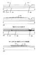
以上の構成に従った作製方法で結晶性珪素膜を形成すると、図9に示す様な外観の薄膜が得られる。図9は非晶質珪素膜の結晶化手段として特開平7−321339号公報記載の技術を用いて本発明を実施した場合の拡大顕微鏡写真であり、長さ数十〜百数十μmにも及ぶ横成長領域901が形成される。
【0015】
なお、この横成長領域901は針状または柱状結晶が結晶化を助長する金属元素を添加した領域(902で示される)に対してほぼ垂直に、かつ、互いに概略平行に結晶成長していくため、結晶方向が揃っているという特徴がある。また、903で示されるのは向かい合った添加領域902から延びてきた針状または柱状結晶がぶつかり合って形成された巨視的な結晶粒界(針状または柱状結晶間の結晶粒界とは区別する)である。
【0016】
さらに、図9に示す横成長領域の内部に着目して、結晶粒内部をさらに微細領域まで拡大したTEM写真が図10である。
【0017】
即ち、本発明の結晶性珪素膜は巨視的には図9の様に大きな横成長領域901で構成される様に見えるが、実は横成長領域901を微視的に観察すると、図10に示す様に針状または柱状結晶1001が複数集合して構成される様な結晶構造体となっている。
【0018】
また、図10において1002で示されるのが針状または柱状結晶同士の境界を示す結晶粒界であり、結晶粒界1002の延びる方向から、針状または柱状結晶1001が互いに概略平行な方向に結晶成長したことが確認できる。なお、本明細書中における結晶粒界とは断りがない限り針状または柱状結晶同士の境界を指す。
【0019】
また、本発明の半導体装置は、ハロゲン元素を含む雰囲気による加熱処理によって結晶化を助長する金属元素(ニッケルを主例とする)がゲッタリング除去され、 5×10¹⁷atoms/cm3 以上の濃度で残留していたニッケルが 1×10¹⁶〜 5×10¹⁷atoms/cm3 (好ましくは活性層中のスピン密度以下)に低減されている。
【0020】
勿論、汚染等により混入した(意図的に添加しない)他の金属元素(Cu、Al等)も同様にゲッタリング除去されていると考えられる。
【0021】
また、この時、シリコン原子の不対結合手は加熱処理の間に酸素と結合して酸化物(酸化珪素)を形成すると予想される。その結果、「悪性の結晶粒界」であった領域には酸化珪素が形成され、実質的に酸化珪素が結晶粒界として機能する構成になると考えられる。
【0022】
この様にして形成された結晶粒界1002は、酸化珪素と結晶珪素との界面が格子欠陥を殆ど含まない整合性に優れた状態になると推測される。これは、熱酸化により酸化珪素が形成される過程と、ニッケルの触媒作用によりシリコン原子同士あるいはシリコン原子と酸素原子との再結合が促進される過程との相乗効果によって欠陥の原因となる格子間シリコン原子が消費されるからである。
【0023】
即ち、図10において1002で示される結晶粒界は、キャリアを捕獲する様な欠陥が殆どなく、針状または柱状結晶内部を移動するキャリアにとって、単にエネルギー的な障壁としてのみ機能する「良性の結晶粒界」として振る舞うと考えられる。
【0024】
また、この様な結晶粒界は優先的に熱酸化反応が進行するので熱酸化膜が他の領域よりも厚く形成される。そのため、結晶粒界近傍に印加されるゲイト電圧が見かけ上小さくなることもエネルギー的な障壁になりうると推測される。
【0025】
また、この加熱処理は700 ℃を超える(代表的には800 〜1100℃)比較的高い温度で行われるため、針状または柱状結晶の内部に存在する転位や積層欠陥といった結晶欠陥がほぼ消滅してしまう。さらに、残存したシリコン原子の不対結合手は膜中に含まれる水素やハロゲン元素によって終端される。
【0026】
従って本発明者らは、以上の様にして得られる図10に示す状態において、複数の針状または柱状結晶の内部の領域を「キャリアにとって実質的に単結晶と見なせる領域」として定義している。
【0027】
「キャリアにとって実質的に単結晶と見なせる」とは、キャリアが移動するに際してキャリアの移動を妨げる障壁がないことを意味しており、結晶欠陥や粒界がないこと、エネルギー的に障壁となるポテンシャルバリアが存在しないことなどと言い換えられる。
【0028】
本発明は上記のような構成でなる結晶性珪素膜を利用してTFTに代表される半導体装置の活性層を構成し、駆動回路やロジック回路を構成するに足る高性能な半導体装置を実現するものである。
【0029】
以上のような本発明の構成について、以下に記載する実施例でもって詳細な説明を行うこととする。
【0030】
【実施例】
〔実施例1〕
本実施例では本発明の作製方法に従って形成した結晶性珪素膜を、薄膜トランジスタ(TFT)の活性層として利用した例を示す。図1に示すのはTFTの作製工程の一実施例である。
【0031】
なお、本実施例で利用する非晶質珪素膜の結晶化手段は、特開平7−321339号公報に記載された技術である。従って、本実施例ではその概略を記載するに止めるので詳細は前記公報を参照すると良い。
【0032】
まず絶縁表面を有する基体101を用意する。本実施例では石英基板上に下地膜として酸化珪素膜102を2000Åの厚さに成膜する。酸化珪素膜102の成膜方法としては減圧熱CVD法、プラズマCVD法、スパッタ法などを用いれば良い。
【0033】
なお、後に非晶質珪素膜を結晶化する際、下地膜が緻密である方が得られる結晶性珪素膜の結晶性が良いことが本発明者らの研究により判っている。また、膜中に 5×10¹⁷〜 2×10¹⁹atoms/cm3 の酸素が含まれると好ましい。膜中に含まれた酸素は後の結晶化を助長する金属元素のゲッタリング処理の際に重要な役割を果たす。
【0034】
次に、非晶質珪素膜103を200 〜1000Å(本実施例では350 Å) の厚さに減圧熱CVD法によって成膜する。成膜ガスとしてはシラン系ガス(SiH4、Si2H6 、Si3H8 等)を用いれば良い。なお、減圧熱CVD法により成膜した非晶質珪素膜は後の結晶化の際に自然核発生率が小さい。この事は個々の結晶が相互干渉する(ぶつかりあって成長が止まる)割合が減るため、横成長幅を大きくする上で望ましい。
【0035】
勿論、非晶質珪素膜103の成膜方法として、プラズマCVD法、スパッタ法等を用いることも可能である。
【0036】
次に、500 〜1200Åの厚さの酸化珪素膜104をプラズマCVD法またはスパッタ法により成膜し、後に結晶化を助長する金属元素を導入する領域のみを選択的にエッチング除去する。即ち、この酸化珪素膜104は非晶質珪素膜103に対してニッケルを選択的に導入するためのマスク絶縁膜として機能する。
【0037】
酸化珪素膜104によって露呈される領域105は、紙面に垂直な方向に長手方向を有するスリット状に形成されている。(図1(A))
【0038】
次に、酸素雰囲気中においてUV光を照射し、領域105によって露呈した非晶質珪素膜103の表面に極薄い酸化膜(図示せず)を形成する。この酸化膜は、後に結晶化を助長する金属元素を導入する際の溶液塗布工程で溶液の濡れ性を改善するためのものである。
【0039】
なお、結晶化を助長する金属元素としては、Fe、Co、Ni、Ru、Rh、Pd、Os、Ir、Pt、Cu、Auから選ばれた一種または複数種類の元素が用いられるが、本実施例ではNi(ニッケル)を例にとって説明する。
【0040】
次に、所定の濃度(本実施例では重量換算で100ppm) でニッケルを含有したニッケル硝酸塩溶液(またはニッケル酢酸塩溶液)を滴下し、スピンコート法によりニッケルを含有した薄い水膜106を形成する。非晶質珪素膜中に添加するニッケル濃度は溶液塗布工程においてニッケル塩溶液の濃度を調節することで容易に制御することができる。(図1(B))
【0041】
次に、不活性雰囲気中において450 ℃、1時間程度の水素出しを行った後、500 〜700 ℃、代表的には550 〜600 ℃の温度で 4〜8 時間の加熱処理(第1の加熱処理)を加えて非晶質珪素膜103の結晶化を行う。こうして結晶性珪素膜107が得られる。(図1(C))
【0042】
この時、結晶成長は針状または柱状結晶が基板に概略平行な方向に進行する。本実施例の場合は、105で示される領域が図面の手前方向から奥手方向に長手方向を有するスリット状となっているので、矢印108で示されるように結晶成長は概略一方向に向かって進行する。この時、結晶成長は数百μm以上に渡って行わすことができる。
【0043】
なお、109で示されるのはニッケル添加領域であり、横成長領域107に比べて高い濃度でニッケルを含有している。添加領域109は結晶核が過度に密集して結晶成長するため結晶性はあまり良くない。従って、後に形成する活性層は添加領域109を除いた領域で構成される。
【0044】
次に、結晶化のための加熱処理が終了したら、ニッケルを選択的に添加するためのマスク絶縁膜となった酸化珪素膜104を除去する。この工程はバッファードフッ酸等により容易に行なわれる。
【0045】
なお、後のハロゲン元素を含む雰囲気中での加熱処理の前および/または後に結晶性珪素膜107に対してエキシマレーザーによるレーザーアニールを施しても構わない。ただし、レーザー照射により結晶性珪素膜の結晶性は改善しうるが、珪素膜表面に凹凸が形成されやすいので注意が必要である。
【0046】
次に、得られた結晶性珪素膜107をパターニングして後にTFTの活性層として機能する活性層110を形成する。なお、本発明では活性層の配置が重要である。その事については後述する。
【0047】
活性層110を形成したら、活性層110上に酸化珪素膜でなるゲイト絶縁膜111を200 〜1500Å( 本実施例では300 Å) の厚さに成膜する。ゲイト絶縁膜111の成膜方法は、プラズマCVD法、熱CVD法、スパッタ法等の気相法を用いれば良い。
【0048】
また、酸化珪素膜の代わりに窒化珪素膜や酸化窒化珪素膜を用いたり、それらの絶縁膜を積層して用いても構わない。
【0049】
次に、ハロゲン元素を含む雰囲気において加熱処理(第2の加熱処理)を行う。この加熱処理はハロゲン元素による金属元素のゲッタリング効果を利用して、活性層110中の金属元素(特にニッケル)を除去することを第1に狙ったものである。(図1(D))
【0050】
このゲッタリングのための加熱処理は、その効果を得るために700 ℃を越える温度で行なうことが重要である。それ以下の温度ではゲイト絶縁膜111がブロッキング層となって十分なゲッタリング効果を得られない恐れがある。
【0051】
そのため、この加熱処理の温度範囲は700 ℃を超える温度で行い、好ましくは800 〜1000℃(代表的には950 ℃)とし、処理時間は 0.1〜 6時間、代表的には
0.5〜 1時間とする。
【0052】
なお、本実施例では、酸素(O2 )雰囲気中に対して塩化水素(HCl)を0.5 〜10体積%の濃度で含有させた雰囲気中において、950 ℃、30分の加熱処理を行う。なお、HCl濃度を上記濃度以上とすると、結晶性珪素膜の膜表面に膜厚と同程度の凹凸が生じてしまうため好ましくない。
【0053】
また、本実施例ではハロゲン元素を含む化合物してHClガスを用いる例を示したが、それ以外のガスとして、HF、NF3 、HBr、Cl2 、ClF3 、BCl3 、F2 、Br2 等のハロゲンを含む化合物から選ばれた一種または複数種のものを用いることが出来る。また、一般にハロゲンの水素化物または有機物(炭水素化物)を用いることもできる。
【0054】
この工程においては針状または柱状結晶の結晶粒界に偏析したニッケルがハロゲン元素(ここでは塩素)の作用によりゲッタリングされ、揮発性の塩化ニッケルとなって大気中へ離脱して除去されると考えられる。
【0055】
従って、活性層110中のニッケルはデバイス特性に影響を与えない程度( 1×10¹⁶〜 5×10¹⁷atoms/cm3 、好ましくは活性層中のスピン密度以下)にまで低減されることがSIMS分析により確認されている。なお、下限の 1×10¹⁶atoms/cm3 という値はSIMSの検出下限界である。また、本明細書における不純物濃度はSIMS分析で得られた計測値の最小値でもって定義される。
【0056】
なお、本発明者らの知見では結晶化の助長に利用されたニッケルは針状または柱状結晶の結晶粒界に多く偏析する傾向にあり、針状または柱状結晶の内部には実質的には殆ど含まれないと考えられる。
【0057】
ところが、現状のSIMS分析では結晶内部と結晶粒界の両方の情報を拾ってしまうので、本明細書中におけるニッケルの濃度は、厳密には結晶内部と結晶粒界とに含まれるニッケル濃度を平均化した平均濃度を意味する。
【0058】
また、ゲッタリング工程を行なった場合、結晶性珪素膜中にはゲッタリング処理に使用したハロゲン元素が 1×10¹⁵〜 1×10²⁰atoms/cm3 の濃度で残存する。その際、結晶性珪素膜と熱酸化膜との間に高濃度に分布する傾向がある。
【0059】
なお、ニッケルは結晶化の際に針状または柱状結晶の結晶粒界へと押し出されて偏析し、ニッケルシリサイドとして存在していたと考えられる。そしてゲッタリングの際に塩化ニッケルとなって離脱し、ニッケルとの結合を切られたシリコンの不対結合手は結晶粒界に多く存在する状態となる。
【0060】
しかし上記工程は酸化性雰囲気中において、比較的高い温度で行われるため形成された不対結合手は容易に酸素と結合して酸化物( SiOX で表される酸化珪素)を形成すると考えられる。即ち、本発明者らは上記一連の加熱工程によって、結晶性珪素膜は酸化珪素が結晶粒界として機能する様な結晶構造体となると考えている。
【0061】
また、残存した不対結合手は活性層110中に含まれる水素やハロゲン元素によって終端されるか、シリコン同士の再結合によって補償され、さらに、転位や積層欠陥といった結晶欠陥はシリコン原子の再結合や再配列によってほぼ消滅してしまうので、針状または柱状結晶の内部の結晶性も著しく改善されると考えられる。
【0062】
従って、活性層110はハロゲン雰囲気での加熱処理によりニッケルがデバイス特性に支障がない程度にまで充分除去され、かつ、活性層110を構成する針状または柱状結晶は著しく結晶性が改善されており、キャリアにとって実質的に単結晶と見なせる領域を有した結晶構造体で構成されている。
【0063】
また、上記加熱処理により活性層110とゲイト絶縁膜111の界面では熱酸化反応が進行し、約 100Åの珪素膜が酸化されて 200Åの熱酸化膜が形成される。即ち、ゲイト絶縁膜111の全膜厚はCVD法で成膜した分と熱酸化で形成された分とを合わせて500 Åとなる。
【0064】
さらに、上記ハロゲン雰囲気における加熱処理を施した後に、窒素雰囲気中で950 ℃1 時間程度の加熱処理を行なうことで、ゲイト絶縁膜111の膜質の向上と共に、極めて良好な半導体/絶縁膜界面が実現される。
【0065】
また、活性層110はドライエッチング法で形成されるが、その時活性層のエッジに残留したプラズマダメージがTFTのリーク電流の原因となる恐れがある。本実施例の場合、活性層110のエッジは熱酸化されるのでプラズマダメージの除去も兼ねている。
【0066】
以上の様にして、ゲイト絶縁膜(熱酸化膜)111の形成まで終了したら、次にゲイト電極を構成するためのアルミニウム膜(図示せず)を2500Åの厚さにスパッタ法でもって成膜する。このアルミニウム膜中には、ヒロックやウィスカー防止のためにスカンジウムを0.2重量%含有させる。
【0067】
なお、本実施例ではゲイト電極(ゲイト配線を含む)を形成する材料としてアルミニムを主成分とする材料を用いているが、他にもタングステン、タンタル、モリブデン等を用いることもできる。また、導電性を付与した結晶性珪素膜をゲイト電極として活用しても構わない。
【0068】
次に、図1(D)に示す様にアルミニウム膜をパターニングしてゲイト電極の原型となる島状のアルミニウム膜のパターン112を形成する。なおこの際利用したレジストマスク(図示せず)はそのまま残存させておく。(図2(A))
【0069】
そして、アルミニウム膜のパターン112を陽極とした陽極酸化を行う。この技術は公知の陽極酸化技術(例えば特開平7−135318号)を用いる。まず、この陽極酸化工程によって、パターン112の側面には多孔質状の陽極酸化膜113が形成される。本実施例ではこの陽極酸化膜113の膜厚を0.7 μmとする。
【0070】
図2(B)に示す多孔質状の陽極酸化膜113を形成したら、図示しないレジストマスクを取り除く。そして、再度の陽極酸化を行うことにより、緻密な陽極酸化膜114を形成する。緻密な陽極酸化膜114の膜厚は900 Åとする。
【0071】
また、以上の工程を経てゲイト電極115が画定する。緻密な陽極酸化膜114は、後の工程においてゲイト電極115の表面を保護したり、ヒロックやウィスカーの発生を抑制するために機能する。
【0072】
次に、緻密な陽極酸化膜114まで形成したら、この状態においてソース/ドレイン領域を形成するための不純物イオンの注入を行う。Nチャネル型のTFTを作製するならばP(リン)イオンの注入を行い、Pチャネル型のTFTを作製するならばB(ボロン)イオンの注入を行えば良い。
【0073】
この工程において、高濃度に不純物が添加されたソース領域116とドレイン領域117が形成される。
【0074】
次に、酢酸とリン酸と硝酸とを混合した混酸を用いて、多孔質状の陽極酸化膜113を選択的に除去した後に再度Pイオンのイオン注入を行なう。このイオン注入は、先のソース/ドレイン領域を形成する際よりも低ドーズ量でもって行なわれる。(図2(C))
【0075】
すると、ソース領域116、ドレイン領域117と比較して不純物濃度の低い、低濃度不純物領域118、119が形成される。そしてゲイト電極115直下の120で示される領域が自己整合的にチャネル形成領域となる。
【0076】
なお、チャネル形成領域120とドレイン領域117との間に配置された低濃度不純物領域119は特にLDD(ライトドープドレイン領域)領域と呼ばれ、チャネル形成領域120とドレイン領域117との間に形成される高電界を緩和する効果を有する。
【0077】
また、チャネル形成領域120(厳密には針状または柱状結晶の内部)は真性または実質的に真性な領域で構成されている。真性または実質的に真性な領域であるとは、活性化エネルギーがほぼ1/2 (フェルミレベルが禁制帯の中央に位置する)であり、かつ、スピン密度よりも不純物濃度が低い領域であること、あるいは意図的にPやBといった不純物を添加しないアンドープ領域であることを意味している。
【0078】
さらに、上記の不純物イオンの注入工程の後、レーザー光または赤外光または紫外光の照射を行うことによって、イオン注入が行われた領域のアニールを行う。この処理によって、添加イオンの活性化と、イオン注入時に活性層が受けた損傷の回復が行なわれる。
【0079】
また、水素化処理を300 〜350 ℃の温度範囲で0.5 〜1時間行うと効果的である。この工程は活性層からの水素脱離によって生成した不対結合手を再び水素終端するものである。この工程を行なうと活性層中には 1×10²¹atoms / cm3 以下、好ましくは 1×10¹⁵〜 1×10²¹atoms / cm3 の濃度で水素が添加される。
【0080】
こうして図2(C)に示す状態が得られたら、次に層間絶縁膜121成膜する。層間絶縁膜121は、酸化珪素膜、または窒化珪素膜、または酸化窒化珪素膜、または有機性樹脂膜、またはそれらの膜の積層膜でもって構成される。(図2(D))
【0081】
また、有機性樹脂膜であるポリイミドを用いると、比誘電率が小さいので上下配線間の寄生容量を低減することができる。また、スピンコート法で形成できるので容易に膜厚を稼ぐことができ、スループットの向上が図れる。
【0082】
次に、層間絶縁膜121コンタクトホールの形成を行い、ソース電極122とドレイン電極123とを形成する。さらに350℃の水素雰囲気中において加熱処理を行うことにより、素子全体の水素化を行い、図2(D)に示すTFTが完成する。
【0083】
図2(D)に示すTFTは説明のため最も単純な構造となっているが、本実施例の作製工程手順に多少の変更・追加を加えることで適宜所望のTFT構造とすることは容易である。
【0084】
ここで、前述の様に活性層110を形成する際に、その配置が重要である理由について説明する。説明は図3を用いて行なう。
【0085】
本実施例を実施した場合、針状または柱状結晶が互いに概略平行に成長するため、結晶粒界が一方向に揃っているという特徴がある。また、結晶化を助長する金属元素を選択的に添加することで、針状または柱状結晶が結晶成長する方向を自由に制御することが可能である。この事は非常に重要な意味を持っている。
【0086】
ここで絶縁表面を有する基体上に活性層を形成した一実施例を図3に示す。図3に示すのは、アクティブマトリクス型液晶表示装置を作製するにあたって基体301上にマトリクス状に配置された活性層である。
【0087】
なお、302の破線で示される領域はニッケルを選択的に導入するための領域が存在した場所である。また、303は横成長領域が互いにぶつかり合って形成された巨視的な粒界が存在した場所である。これらは活性層を形成した後では確認できないため点線で示すことにする。
【0088】
また、本実施例で示した手段で結晶化を行なう場合、針状または柱状結晶はニッケル添加領域302に対して概略垂直な方向(図中において矢印で示される方向)に成長する。
【0089】
従って、図3の様に島状半導体304を配置することで、チャネル方向と、針状または柱状結晶の結晶粒界とを概略一致する方向に揃えることができる。しかも、ニッケル添加領域302を基板301の端から端まで達する様に設計することで、基板全面において前述の様な構成を実現することが可能である。
【0090】
この様な構成とすると、チャネル方向と針状または柱状結晶の並ぶ方向とが一致することになる。即ち、TFTの活性層として機能する際に、チャネル形成領域においてキャリアの移動を妨げるエネルギー障壁が極めて少ないことを意味しており、動作速度のさらなる向上が期待できるのである。
【0091】
また、以上のことは、換言すれば針状または柱状結晶の方向性をチャネル方向に対して特定の角度を有する様に制御することができることを意味する。図3は特定の角度を0°とした場合に相当する。
【0092】
即ち、図3とは別の視点で考えると活性層304を90°回転させた場合も考えられる。その場合、キャリアの移動度は低下するが、低オフ電流特性、高耐圧特性を期待しうる。
【0093】
ここで、本実施例に従って本発明者らが作製した図2(D)に示される半導体装置の電気特性を図4に示す。図4(A)はNチャネル型TFTの電気特性(Id−Vg 特性) 、図4(B)はPチャネル型TFTの電気特性を示している。なお、Id−Vg 特性を示すグラフは5点分の測定結果をまとめて表示する。
【0094】
横軸のVGはゲイト電圧値、縦軸のIDはソース/ドレイン間を流れる電流値である。また、401、403で示されるId−Vg 特性(Id−Vg 曲線)はドレイン電圧VD=1Vの時の特性を示し、402、404で示されるId−Vg 特性はドレイン電圧VD=5Vの時の特性を示している。また、405、406はドレイン電圧VD=1Vの時のリーク電流を示している。
【0095】
なお、オフ領域(図4(A)では−1V 以下、図4(B)では−1V 以上)のドレイン電流(Ioff) と、オンおよびオフ領域のリーク電流(IG)は、殆どが 1×10⁻¹³ A(測定下限界)以下であるので、図4(A)、(B)ではノイズと混同されてしまっている。
【0096】
ここで、図4(A)、(B)に示される電気特性から求めた、本発明によるTFTの代表的な特性パラメータを表1、表2に示す。なお、表1はNチャネル型TFTの電気特性(任意の20点測定)の結果であり、表2はPチャネル型TFTの電気特性(任意の20点測定)の結果を示している。
【0097】
【表1】

【表2】
表1、表2において特に注目すべき点は、サブスレッショルド特性(S値、S−value)が60〜100mV/dec の間に収まる程小さく、移動度(μFE、モビリティ)が150 〜300cm2/Vs という様に極めて大きいことである。なお、本明細書中において移動度とは電界効果移動度を意味する。
【0100】
これらの測定データは従来のTFTでは達成不可能な値であり、まさに本発明によるTFTが単結晶上に作製したMOSFETに匹敵する極めて高性能なTFTであることを証明している。
【0101】
また同時に、本発明によるTFTは非常に劣化に強いことが繰り返し測定による加速劣化試験によって確認されている。経験的には高速動作するTFTは劣化しやすいという欠点を有しているのだが、本発明によるTFTは劣化もなく、極めて高い耐圧特性を有していることが判明している。
【0102】
また、表1、表2には参考として平均値および標準偏差(σ値)も記載する。標準偏差は平均値からの分散(バラツキ)の尺度として用いられる。一般的には測定結果(母集団)が正規分布(ガウシアン分布)に従うとすると、平均値を中心に±1σの内に全体の68.3%、±2σの内に95.4%、±3σの内に99.7%が入ることが知られている。
【0103】
本発明者らは、本実施例のTFT特性の分散をより正確に評価するため、540 個のTFTを測定し、その結果から平均値および照準偏差を求めた。その結果、S値の平均値は80.5mV/dec(n−ch)、80.6mV/dec(p−ch)であり、標準偏差は5.8(n−ch) 、11.5(p−ch)であった。また、移動度(max) の平均値は194.0cm2/Vs(n−ch) 、131.8cm2/Vs(p−ch) であり、標準偏差は38.5(n−ch)、10.2(p−ch)であった。
【0104】
即ち、本発明を利用したNチャネル型TFTにおいては、以下に示す様なTFT特性を得ることができる。
(1)S値のσ値が10mV/dec以内、好ましくは5mV/dec 以内に収まる。
(2)S値が80±30mV/dec以内、好ましくは80±15mV/dec以内に収まる。
(3)μFEのσ値が40cm2/Vs以内、好ましくは35cm2/Vs以内に収まる。
【0105】
また、本発明を利用したPチャネル型TFTにおいては、以下に示す様なTFT特性を得ることができる。
(1)S値のσ値が15mV/dec以内、好ましくは10mV/dec以内に収まる。
(2)S値が 80±45mV/dec以内、好ましくは80±30mV/dec以内に収まる。
(3)μFEのσ値が15cm2/Vs以内、好ましくは10cm2/Vs以内に収まる。
【0106】
以上の様に、本発明によるTFTは極めて優れた電気特性を実現するものであり、これまで単結晶上に作製したMOSFETのみが使用されていた様な複雑なSRAM回路やDRAM回路等、高速動作を必要とするロジック回路を構成することが可能である。
【0107】
また、本実施例ではシングルゲイト構造のTFTの作製工程例のみを記載しているが、ダブルゲイト構造のTFTやそれ以上のゲイト電極を有するマルチゲイト構造のTFTに対しても適用することができる。
【0108】
また、本発明は活性層の結晶性を高めることで実現できるものであって、耐熱性が許す限りTFT構造は問わずに実施することができる。
【0109】
〔本発明で得られる結晶構造体に関する知見〕
本発明によって得られる結晶性珪素膜が図10に示される様な針状または柱状結晶の集合体でなる結晶構造体であることは既に述べた。ここでは、本発明による結晶構造体と他の方法で形成された結晶構造体との比較を行なう。
【0110】
図11に示す写真は、実施例1の手順で非晶質珪素膜の結晶化までを終えた試料のTEM写真である。即ち、ハロゲン元素を含む加熱処理を行なっていない結晶性珪素膜の結晶構造を示している。
【0111】
図11において確認できる様に、結晶化直後の針状または柱状結晶の内部には多数の転位欠陥(1101で示される円内)が存在する。しかしながら、図10に示すTEM写真では、結晶内部にその様な転位欠陥は確認されず、きれいな結晶構造となっていることが判る。
【0112】
この事は、本発明においてハロゲン元素を含む雰囲気での加熱処理が結晶性の改善に大きく寄与していることの証拠となる。
【0113】
また、図12に示す結晶構造体は、非晶質珪素膜の結晶化条件を本発明とは異なるものとした場合の例である。具体的には、窒素雰囲気中で600 ℃48時間の加熱処理を行うことで非晶質珪素膜を結晶化し、900 〜1100℃程度の温度で熱酸化処理を施してある。
【0114】
以上の様にして形成した結晶性珪素膜は、図12に示す様に個々の結晶粒が大きく、不規則に分布する粒界によって分割された状態となっている。
【0115】
図12において、結晶粒1201は不規則な粒界1202によって囲まれた状態となっている。従って、実際に図12に示す結晶構造体をTFTの活性層として利用すると、不規則な粒界1202によって生ずるエネルギー障壁がキャリアの移動を阻害してしまう。
【0116】
一方、図10に示す様な結晶構造体は、図10に示す様に、結晶粒界1002がある程度の規則性をもって配列した状態となっている。従って、針状または柱状結晶の内部において、キャリアの移動を阻害するエネルギー障壁はないと考えられる。
【0117】
なお、本発明者らが針状または柱状結晶の配列状態を1〜5万倍程度の広視野で観察した結果、針状または柱状結晶がジグザグに進行する様な場合があることが確認されている。これは、結晶成長がエネルギー的に安定な方向へ向かうことに起因する現象であり、結晶方向が転換した箇所には一種の粒界が形成されていると推測される。
【0118】
しかしながら本発明者らは、針状または柱状結晶の内部に生じうるこの粒界はエネルギー的に不活性な双晶粒界の如きものではないかと推測している。即ち、結晶方向は異なるが、整合性良く連続的に結合した粒界であり、キャリアの移動を妨げる程のエネルギー障壁とならない(実質的に粒界と見なされない)粒界であると考えている。
【0119】
以上の様に、一般的なプロセスで結晶化した結晶性珪素膜は図12に示す様な結晶構造を有し、キャリアの移動を遮る様に不規則な粒界が分布するため、高い移動度を達成することが困難である。
【0120】
しかしながら、本発明による結晶性珪素膜は図10に示す様な結晶構造を有し、結晶粒界が概略一方向に揃っている上、針状または柱状結晶の内部は実質的にエネルギー障壁となる粒界が存在しないと考えられる。即ち、キャリアは何ら阻害されることなく結晶内部を移動することが可能となるので、極めて高い移動度を達成することができる。
【0121】
特に、本発明により得られる針状または柱状結晶の注目すべき点は、凹凸や応力等に起因する歪みを避けながら(結晶方向を変えながら)数十〜数百μmもの距離を連続的に成長していくと考えられる点である。
【0122】
本発明者らの推測が正しければ、本発明による結晶性珪素膜は結晶内部にキャリアトラップとなりうる粒界を形成しないで成長していく、特殊な結晶の集合体で構成される全く新しい結晶構造体であると言える。
【0123】
〔実施例2〕
本実施例は実施例1で示したTFTでもってCMOS回路を形成する例である。CMOS回路は実施例1で示した様な構造のNチャネル型TFTとPチャネル型TFTとを相補的に組み合わせて構成される。
【0124】
本実施例におけるCMOS回路の作製工程の一実施例を図5、図6を用いて説明する。なお、本発明により形成される結晶性珪素膜の応用範囲は広く、CMOS回路を形成する方法は本実施例に限ったものではない。
【0125】
まず実施例1に示す作製手順に従って、石英基板501上に酸化珪素膜502を成膜し、その上に結晶性珪素膜(図示せず)を得る。そしてそれをパターニングすることによりNチャネル型TFTの活性層503とPチャネル型TFTの活性層504とを形成する。
【0126】
活性層503、504を形成したらゲイト絶縁膜505を成膜し、さらにハロゲン元素を含む雰囲気における加熱処理を行なう。本実施例では処理条件を実施例1と同じものとする。こうして、活性層503、504は本発明の結晶構造体となり、良好な膜質と界面を有するゲイト絶縁膜505が形成される。
【0127】
次に、後にゲイト電極の原型を構成するアルミニウム膜(図示せず)を成膜し、パターニングしてアルミニウム膜のパターン506、507を形成する(パターン形成後もパターニングに使用したレジストマスクは残しておく)。
【0128】
こうして図5(A)の状態が得られる。アルミニウム膜のパターン506、507を形成したら、次に、実施例1と同様の条件でもってアルミニウム膜のパターン506、507の側面に多孔質の陽極酸化膜508、509を形成する。本実施例ではこの多孔質の陽極酸化膜508、509の膜厚を0.5 μmとする。
【0129】
さらに、実施例1と同様の条件でもって緻密で強固な陽極酸化膜510、511の形成を行う。ただし、本実施例ではこの膜厚が700 Åとなる様に到達電圧を調節する。また、この工程によりゲイト電極512、513が画定する。こうして図5(B)の様な状態が得られる。
【0130】
図5(B)の状態が得られたら、ゲイト絶縁膜505をドライエッチング法によりエッチングする。このエッチング工程ではゲイト電極512、513および多孔質状の陽極酸化膜508、509がマスクとなって、その直下のみにゲイト絶縁膜が残存する。エッチング後に多孔質状の陽極酸化膜508、509を除去すると図5(C)の状態となる。
【0131】
次に、Pチャネル型TFTを覆い隠す様にしてレジストマスク514を形成し、N型を付与する不純物としてP(リン)イオンをドーピングする。このドーピングは、加速電圧50KeV 、ドーズ量 0.1〜 5×10¹³atoms/cm2 、好ましくは 0.5〜 2×10¹³atoms/cm2 atoms/cm2 で行なう。
【0132】
このドーピング工程は比較的加速電圧が高いため、Pイオンが露出したゲイト絶縁膜を通過して活性層503へと打ち込まれる。その結果、515、516で示される領域にPイオンが添加される。(図5(C))
【0133】
次に、図5(D)に示すように再びPイオンの注入を行う。このPイオンの注入は、加速電圧を 5KeV と低めに設定し、ドーズ量を0.1 〜 1×10¹⁵atoms/cm2 、好ましくは 2〜 5×10¹⁴atoms/cm2 とする。この工程の結果、高濃度にPイオンが添加された領域517、518が形成される。
【0134】
図5(D)に示す工程が終了した時点でNチャネル型TFTの活性層が完成する。即ち、Nチャネル型TFTのソース領域517、ドレイン領域518、低濃度不純物領域(またはLDD領域)519、520、チャネル形成領域521が画定する。
【0135】
次に、図6(A)に示すように左側のNチャネル型TFTを覆うレジストマスク522を形成する。そして、図6(A)に示す状態においてP型を付与する不純物としてB(ボロン)イオンの注入を行う。このBイオンのドーピングもPイオンの場合と同様に2度に分けて行なう。
【0136】
1度目のBイオンのドーピングは加速電圧30KeV 、ドーズ量を 0.1〜 5×10¹⁴atoms/cm2 、好ましくは 0.5〜 2×10¹⁴atoms/cm2 程度とする。この工程により523、524で示される領域にBイオンが添加される。(図6(A))
【0137】
2度目のBイオンのドーピングは加速電圧 5KeV 、ドーズ量を 0.1〜 1×10¹⁵atoms/cm2 、好ましくは 2〜 5×10¹⁴atoms/cm2 程度とする。この工程により高濃度にBイオンが添加された領域525、526が形成される。(図6(B))
【0138】
以上の工程によりPチャネル型TFTのソース領域525、ドレイン領域526、低濃度不純物領域(またはLDD領域)527、528、チャネル形成領域529が画定する。
【0139】
次に、図6(B)に示す工程の終了後、レジストマスク522を取り除き、基板全面にレーザー光または赤外光や紫外光等の強光を照射する。この工程により添加された不純物イオンの活性化と、不純物イオンが注入された領域の損傷の回復が行なわれる。
【0140】
次に、層間絶縁膜530を4000Åの厚さに成膜する。層間絶縁膜530は酸化珪素膜、酸化窒化珪素膜、窒化珪素膜、有機性樹脂膜のいずれでも良く、多層構造としても良い。これら絶縁膜の成膜方法は、プラズマCVD法、熱CVD法、スピンコート法を用いればよい。
【0141】
次にコンタクトホールの形成を行い、Nチャネル型TFTのソース電極531、Pチャネル型TFTのソース電極532を形成する。また、ドレイン電極533はNチャネル型TFTとPチャネル型TFTとで共有する様な構成とすることでCMOS回路が実現される。(図6(C))
【0142】
以上の様な過程を経て、図6(C)に示す構造でなるCMOS回路を作製することができる。CMOS回路は最も単純な構成のインバータ回路であり、CMOSインバータ回路を直列に奇数組接続して形成した閉回路はリングオシレータと呼ばれ、半導体装置の動作速度を評価する際に用いられる。
【0143】
ここで図7(A)に示す上面写真は、本実施例に従って作製したCMOS回路を組み合わせて構成したリングオシレータ回路である。本発明者らは本発明を利用して実際にアクティブマトリクス型液晶表示装置を試作し、その駆動回路の動作性能をリングオシレータで確認した。
【0144】
なお、図7(A)に示すリングオシレータを構成するCMOS回路のゲイト電極幅は約0.6 μmと細く、チャネル形成領域は通常ならば短チャネル効果が発生する程度にまで微細化されている。
【0145】
また、図7(B)には参考としてシフトレジスタ回路の写真を示す。図7(B)に示すシフトレジスタ回路は試作した周辺駆動回路を構成する重要な回路の一つであり、画素領域のアドレスを指定するロジック回路である。特に、水平走査用(ソース側用)シフトレジスタ回路は実動作時に数MHz〜数十MHz程度の非常に高い周波数での駆動を要求される。
【0146】
リングオシレータ回路の発振周波数は9、19、51組(段)のCMOS回路を接続したリングオシレータで測定した。その結果、電源電圧3〜5V、9段のリングオシレータで 300MHz以上、中には500 MHzを超える発振周波数が得られており、極めて動作速度が速いことが判明した。
【0147】
これらの値は従来の作製工程で作製したリングオシレータに比べて20倍近い動作速度を有することを意味している。また、1〜5Vの範囲で電源電圧を振っても常に数十〜数百MHzの発振周波数を実現している。
【0148】
以上の様に、本発明を利用したCMOS回路は回路設計上やむを得ず付加価値が加わった状況においても、問題なく高速動作させることが可能であり、あらゆるロジック回路の要求に応える性能を有している。
【0149】
さらに、チャネル長が0.6 μmと極めて微細化されているにも拘わらず、本実施例に示した様な極めて高速な動作にも耐えうる高い耐圧特性をも有していることは、本発明によるTFTが短チャネル効果に殆ど影響されず、極めて高い信頼性を有していることを意味している。
【0150】
〔本発明の構成から導かれる推察〕
実施例1および実施例2で示した様に、本発明に従って作製したTFTは極めて高い性能(高速動作特性、高耐圧特性)を実現している。また、この様な高速動作特性を有していながら劣化に強いという特徴は、経験的にも特異な現象と言える。そこで、本発明者らは本発明によるTFTが何故これほどまで耐劣化性に優れているかを考察し、そこから一つの理論を推察したので以下に記載する。
【0151】
本発明者らは、本発明によるTFTの耐圧が高い理由として針状または柱状結晶の結晶粒界の影響を重視した。即ち、本発明者らはチャネル形成領域に局部的に存在する結晶粒界(酸化物領域と予想される)がソース領域とドレイン領域の間、特にチャネル形成領域とドレイン領域との間にかかる高電界を効果的に緩和していると推測した。
【0152】
具体的には、結晶粒界が特にドレイン領域から広がる空乏層電荷により形成される電界を抑え、ドレイン電圧が高くなった状態(ドレイン側空乏層電荷が増加した状態)においても、ソース側の拡散電位を変化させない様に機能していると考えたのである。
【0153】
以上をまとめると、本発明による結晶性珪素膜を活性層に活用した場合、チャネル形成領域は以下の構成を満たしていると見なせる。
(1)キャリアが移動する(キャリアにとって)実質的に真性な領域(針状または柱状結晶の内部)が存在する。
(2)キャリアの移動を抑制する又はチャネル方向(ソース−ドレイン間を結ぶ方向)にかかる電界を緩和するエネルギー障壁が存在する。
【0154】
従って、上記2つの構成を満たす、換言すればキャリアにとって実質的に真性なチャネル形成領域と、局部的に形成されたエネルギー障壁とを有する構成とすることで本発明が示す様な優れた特性のTFTを作製しうると考えられる。
【0155】
以上の構成は、多少の推測を交えてではあるが、本発明者らの実験データから導かれるものである。そこで、本発明者らはこの構成を人為的に創り出すことで同様の効果を得ることができるのではないかと予想した。
【0156】
その結果、本発明者らは短チャネル効果の抑制に効果的な構成を提案するに至った。ここではその概略について、以下に記載する。なお、以下に記載する考察は現状においては推測の範囲に止まるものである。
【0157】
短チャネル効果とは、しきい値電圧の低下、パンチスルー現象に伴う耐圧の劣化およびサブスレッショルド特性の劣化などの総称である。特に問題となるパンチスルー現象はドレイン側の空乏層がソース領域にまで広がることでソース側の拡散電位が低下し、ソース/ドレイン間に貫通電流が流れる現象である。
【0158】
そこで本発明者らは本発明の結晶粒界の効果に注目して、チャネル長が0.01〜2 μm程度の短チャネルTFTにおいては、チャネル形成領域に対して人為的かつ局部的に不純物領域を設けることで、ドレイン側の空乏層の広がりを抑制する効果が得られると推測した。
【0159】
この様な構成は活性層を図8に示す様な構成とすることで達成できると考えられる。図8(A)において、801はソース領域、802はドレイン領域、803はチャネル形成領域であり、チャネル形成領域803の中には人為的に不純物領域804が形成される。また、チャネル形成領域803中、不純物領域804以外の領域805は、実質的に真性な領域であり、キャリアが移動する領域となる。
【0160】
ここで図8(A)に示す構造は、図10に示す本発明の結晶構造体を模した構造である点が重要である。即ち、図10の1001で示される結晶粒界は図8(A)の不純物領域804に相当し、図10の針状または柱状結晶は図8(A)のキャリアが移動する領域805に相当するのである。
【0161】
従って、チャネル形成領域803内に配置された不純物領域804はチャネル形成領域内に局部的にビルトインポテンシャル(エネルギー障壁とも言える)の大きい領域を形成し、そのエネルギー障壁によってドレイン側空乏層の広がりを効果的に抑制すると推測できる。
【0162】
また、図8(A)をA−A’で切断した断面図を図8(B)に示す。806は絶縁表面を有する基板である。また、図8(A)をB−B’で切断した断面図を図8(C)に示す。
【0163】
なお、図8(C)においてwpi,nは不純物領域804の幅を表し、wpa,mはキャリアが移動する領域の幅を表す。ここでn、mはチャネル形成領域803内において、wpi,nがn番目の不純物領域の幅であり、wpa,mがm番目のキャリアが移動する領域であることを意味している。
【0164】
従って、本発明によるTFTの実際の電界効果移動度は次式に示す理論式に実効的なチャネル幅Wpa(wpa,mを1〜mまで加えた総和)を代入しなくてはならない。
【0165】
μFE=1/ Cox(ΔId/ ΔVg)・1/ Vd・L/ W
ここでCoxはゲイト酸化膜容量、ΔId、ΔVgはそれぞれドレイン電流Idとゲイト電圧Vgの変化量、Vdはドレイン電圧、L、Wはそれぞれチャネル長およびチャネル幅である。
【0166】
しかしながら、実効的なチャネル幅Wpaを測定することは現実的に不可能であるため、本明細書中の電界効果移動度はチャネル幅の設計値Wを代入して求めている。即ち、実際の移動度よりも小さい値が得られていると考えられる。
【0167】
また、不純物領域を図8(A)に示す様な配置で設けることは移動度の向上に対して非常に大きな意味があると予想される。その理由について以下に説明する。
【0168】
移動度(μFE) は半導体膜(ここでは珪素膜を例にとる)中のキャリアの散乱によって決まるが、珪素膜における散乱は格子散乱と不純物散乱とに大別される。これらが影響し合って形成される全体的な移動度μは次式で表される。
【0169】
【数1】
この数1で示される式は、全体的な移動度μが、格子散乱の影響を受けた場合の移動度μl ( lはlattice を意味する) の逆数および不純物散乱の影響を受けた場合の移動度μi ( iはimpurityを意味する) の逆数の和に反比例することを意味している。また、格子散乱および不純物散乱は各々次式で表される。
【0171】
【数2】
【数3】
これらの式によると、チャネル形成領域全体に均一に不純物が添加された状態では不純物散乱の影響を受けて移動度を稼ぐことができない。しかしながら、図12に示す構成の場合、局部的に不純物領域を形成しているので、キャリアが移動する領域には不純物が添加されず、キャリアにとって実質的に真性である。
【0174】
即ち、理論的には数3においてイオン化した不純物の濃度Ni を限りなく0に近づけることを意味するため、移動度μi は限りなく無限大に近づいていくことになる。即ち、数1において1/μi の項を無視することができる程度にまで不純物を減少させることを意味するので全体の移動度μは限りなく移動度μl に近づいていくと推測される。
【0175】
また、図8(A)において不純物領域804がチャネル方向と概略平行となる様に配置されていることは重要である。この様な配置は、図10に示した針状または柱状結晶の結晶粒界の延びる方向と、チャネル方向とが一致した場合に相当する。
【0176】
この様な配置とした場合、不純物領域804は「良性の結晶粒界」として振る舞うと予想されるので、キャリアを捕獲することなく、レールの様な役割を果してキャリアに移動方向を規定すると推測される。このことは、キャリア同士の衝突による散乱の影響を低減する上で非常に重要な構成である。
【0177】
また、以上の様な構成とすることで、短チャネル効果の一つであるしきい値電圧の低下も抑制できると予想される。これはチャネル幅が極端に狭くなった時に生じる狭チャネル効果を、不純物領域間で人為的に引き起こすことが可能であるという推論に基づく予想である。
【0178】
また、前述の様にドレイン側空乏層の広がりを抑制することでパンチスルー現象を抑制することが可能と考えられるが、パンチスルー現象を抑制することで耐圧の向上と共にサブスレッショルド特性(S値)の向上も望める。
【0179】
サブスレッショルド特性の向上は、本構成を用いることでドレイン側空乏層の占める体積を減じることができるという推論から以下の様に説明できる。
【0180】
図8(A)で示す構成とした時に、効果的に空乏層の広がりが抑制されるならば、ドレイン側空乏層の占める体積を大幅に減じることが可能でなはずである。従って、総合的な空乏層電荷を小さくできるため、空乏層容量を小さくできると考えられる。ここで、S値を導出する式は次の近似式で表される。
【0181】
【数4】
数4において、kはボルツマン定数、Tは絶対温度、qは電荷量、Cd は空乏層容量、Citは界面準位の等価容量、Coxはゲイト酸化膜容量である。従って、本構成では空乏層容量Cd および界面準位の等価容量Citを0に可能な限り近づけることで、Cd =Cit=0となる理想状態、即ちS値が60mV/decade となる半導体装置を実現できる可能性がある。
【0183】
ただし、数4に示される式はS値を導出するための近似式であり、TFTではこの近似式に従わずに60mV/decade 以下の測定値が得られることもある。
【0184】
ところで、本発明から推測される本構成では、本発明の結晶粒界に相当する不純物領域として酸素以外に窒素や炭素を用いても良い。これは、本構成の目的がチャネル形成領域に対して人為的にエネルギー障壁を配置することにあるからである。
【0185】
従って、エネルギー障壁を形成するという観点から考えれば、反転層の導電型と逆の導電型を持つ不純物領域でも効果があると言えよう。即ち、Nチャネル型半導体装置ならばBイオンを、Pチャネル型半導体装置ならばPイオンを用いて不純物領域を形成すれば良いと言える。
【0186】
また、不純物領域をPまたはBイオンで構成する場合、添加する不純物イオンの濃度で直接的にしきい値制御を行なうことも可能である。
【0187】
以上の様に、本構成は本明細書で開示する発明の構成および実験事実をもとに本発明者らの推測により導かれた技術である。本構成を実施することで、チャネル長が極めて短いディープサブミクロン領域の半導体装置で問題となる短チャネル効果を効果的に抑制することができると推測される。
【0188】
〔実施例3〕
本実施例では実施例1に示した作製工程とは別の工程例を示す。具体的には活性層を形成する前に、結晶性珪素膜に対してハロゲン元素を含む雰囲気における加熱処理を施し、ニッケルをゲッタリング除去する。
【0189】
本実施例に示す工程を実施例1と組み合わせることで活性層中のニッケル濃度をさらに効果的に低減することが可能である。
【0190】
また、700 ℃を超える加熱処理によって結晶性珪素膜の膜厚が減少するため、活性層を薄くする効果もある。膜厚が薄くなると移動度の向上やオフ電流の低減といった効果が期待できる。
【0191】
〔実施例4〕
本実施例では実施例1に示した作製工程とは別の工程例を示す。具体的には実施例1において、ゲイト絶縁膜111を成膜する工程を省略し、活性層を形成した直後にハロゲン元素を含む雰囲気での加熱処理を施す。
【0192】
この時形成された熱酸化膜に対して、実施例1と同様に窒素雰囲気中でアニールすることで膜質を改善することができる。この場合、この様な熱酸化膜のみでゲイト絶縁膜を構成することが可能である。また、熱酸化膜の膜厚は加熱処理の条件を調節することで100 〜1500Å(代表的には500 〜1000Å)の範囲で形成できる。
【0193】
熱酸化膜のみでゲイト絶縁膜を構成すると高速動作の可能な半導体装置を作製できる点と、ゲイト絶縁膜の成膜工程を簡略化できる点に特徴がある。ただし、膜厚を均一に形成することが困難な場合が多い。
【0194】
また、上記工程で形成された熱酸化膜の上に気相法により絶縁膜を堆積して、それらの積層膜をもってゲイト絶縁膜とすることも可能である。その場合、ゲイト耐圧が向上するが、熱酸化膜と気相法による膜との界面を清浄にしておくことが重要である。
【0195】
また、上記工程を金属元素(特にニッケル)の除去工程として見なし、上記工程で形成された熱酸化膜を除去して、再度熱酸化膜を形成してゲイト絶縁膜とすることもできる。また、熱酸化膜を除去した後、活性層上に気相法によってゲイト絶縁膜を形成することもできる。この場合、活性層とゲイト絶縁膜の界面に存在する余計な不純物の濃度を低減することが可能であるが、活性層表面の清浄度に注意しなくてはならない。
【0196】
〔実施例5〕
本実施例では、本発明を応用して作製したTFTをDRAM(Dynamic Rondom Access Memory)およびSRAM(Static Rondom Access Memory )に応用した例について説明する。説明には図13を用いることとする。
【0197】
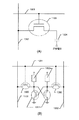
DRAMは記憶する情報を電荷としてコンデンサに蓄える形式のメモリである。コンデンサへの情報としての電荷の出し入れは、コンデンサに直列に接続されたTFTによって制御される。DRAMの1個のメモリセルを構成するTFTとコンデンサの回路を図13(A)に示す。
【0198】
ワード線1301によってゲイト信号を与えられると、1303で示されるTFTは導通状態となる。この状態でビット線1302側からコンデンサ1304に電荷が充電されて情報を読み込んだり、充電したコンデンサから電荷を取り出して情報を読みだしたりする。即ち、このコンデンサに蓄積された電荷をTFTにより書き込んだり、読み出したりすることで記憶素子としての機能を有することになる。
【0199】
DRAMの特徴は1個のメモリを構成する素子数がTFTとコンデンサだけで非常に少ないので、高集積密度の大規模メモリを構成するのに適している。また、価格も低く抑えられるので、現在最も大量に使用されている。
【0200】
また、TFTを用いてDRAMセルを形成した場合の特徴として蓄積容量を小さく設定することができるため、低電圧での動作を可能とすることができる。
【0201】
次に、受動負荷素子として高抵抗を用いたSRAM回路を図13(B)に示す。なお、受動負荷素子と同様の機能をTFTで代替するSRAM構造をとることも可能である。
【0202】
SRAMはフリップフロップ等の双安定回路を記憶素子に用いたメモリであって、双安定回路のON−OFFあるいはOFF−ONの2安定状態に対応して2進情報値(0または1)を記憶するものである。電源の供給がある限り記憶が保持される点で有利である。
【0203】
1305で示されるのはワード線であり、1306はビット線である。1307は高抵抗で構成される負荷素子であり、1308で示されるような2組のドライバトランジスタと1309で示されるような2組のアクセストランジスタとでSRAMが構成される。
【0204】
以上のような構成でなるSRAMの特徴は、高速動作が可能で、信頼性が高くシステムへの組む込みが容易なことなどである。
【0205】
〔実施例6〕
本実施例では、実施例1の半導体装置および実施例2のCMOS回路を用いて同一基体上に画素マトリクス回路とロジック回路とを集積化したアクティブマトリクス型電気光学装置を構成する例を示す。電気光学装置としては、液晶表示装置、EL表示装置、EC表示装置などが含まれる。
【0206】
なお、ロジック回路とは、周辺駆動回路やコントロール回路等の様に電気光学装置を駆動するための集積化回路を指す。アクティブマトリクス型電気光学装置においては、動作性能の限界や集積度の問題もあってロジック回路は外付けICが一般的であったが、本発明のTFTを用いることで同一基板上に全てを一体化することが可能となる。
【0207】
また、コントロール回路とはプロセッサ回路、メモリ回路、クロック発生回路、A/D(D/A)コンバータ回路等の電気光学装置を駆動するに必要な全ての電気回路を含むものとする。勿論、メモリ回路には実施例5、6で示したSRAM回路やDRAM回路が含まれる。
【0208】
このような構成に本明細書で開示する発明を利用すると、単結晶上に形成したMOSFETに匹敵する性能を有するTFTでもってロジック回路を構成することができる。
【0209】
〔実施例7〕
本実施例では実施例1と異なる構造のTFTを作製する例を示す。説明には図14を用いる。
【0210】
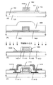
まず、実施例1と同様の工程を経て図2(B)に示す状態を得る。図2(B)に示す状態を得たら、アルミニウム膜のパターニングに用いた図示しないレジストマスクを除去し、その後、酒石酸中で陽極酸化処理を行い、1000Åの厚さの緻密な陽極酸化膜を得る。この状態を図14(A)に示す。
【0211】
図14(A)において、101は石英基板、102は下地膜、110は活性層、111は後にゲイト絶縁膜として機能する熱酸化膜である。また、1401はアルミニウムを主成分とする材料でなるゲイト電極、1402はゲイト電極1401を陽極酸化して得られた緻密な陽極酸化膜である。
【0212】
次に、この状態で活性層110に対して一導電性を付与する不純物イオンの注入を行なう。そして、このイオン注入工程により不純物領域1403、1404が形成される。
【0213】
不純物イオンの注入が終了したら、窒化珪素膜1405を 0.5〜1 μmの厚さに成膜する。成膜方法は減圧熱CVD法、プラズマCVD法、スパッタ法のいずれであっても良い。また、窒化珪素膜以外に酸化珪素膜を用いても良い。
【0214】
こうして図14(B)の状態が得られる。図14(B)の状態が得られたら、次に窒化珪素膜1405をエッチバック法によりエッチングして、ゲイト電極1401の側壁にのみ残す。こうして残された窒化珪素膜はサイドウォール1406として機能する。
【0215】
この際、熱酸化膜111はゲイト電極がマスクとなった領域以外が除去されて図14(C)に示す様な状態で残存する。
【0216】
図14(C)に示す状態で再び不純物イオンの注入を行なう。この時、ドーズ量は先程のイオン注入のドーズ量よりも高めとしておく。このイオン注入の際、サイドウォール1406の直下の領域1407、1408はイオン注入が行なわれないので、不純物イオンの濃度に変化はない。しかし、露出した領域1409、1410はさらに高濃度の不純物イオンが注入されることになる。
【0217】
以上の様に2度目のイオン注入を経て、ソース領域1409、ドレイン領域1410およびソース/ドレイン領域よりも不純物濃度の低い低濃度不純物領域(LDD領域)1407、1408が形成される。なお、ゲイト電極1401の直下はアンドープな領域であり、チャネル形成領域1411となる。
【0218】
以上の工程を経て図14(C)の状態が得られたら、300 Åの厚さの図示しないチタン膜を成膜し、チタン膜とシリコン(結晶性珪素)膜とを反応させる。そして、チタン膜を除去した後、ランプアニール等による加熱処理を行なうことでソース領域1409、ドレイン領域1410の表面にチタンシリサイド1412、1413を形成する。(図14(D))
【0219】
なお、上記工程はチタン膜の代わりにタンタル膜、タングステン膜、モリブデン膜等を用いることも可能である。
【0220】
次に、層間絶縁膜1414として酸化珪素膜を5000Åの厚さに成膜し、ソース電極1415、ドレイン電極1416を形成する。こうして図14(D)に示す構造のTFTが完成する。
【0221】
本実施例で示す構造のTFTは、ソース/ドレイン電極がチタンシリサイド1412、1413を介してソース/ドレイン領域と接続するので良好なオーミックコンタクトを実現できる。
【0222】
〔実施例8〕
本実施例では実施例1または実施例7と異なる構造のTFTを作製する例を示す。説明には図15を用いる。
【0223】
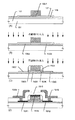
まず、実施例1と同様の工程を経て図2(B)に示す状態を得る。ただし、本実施例ではゲイト電極の材料として導電性を付与した結晶性珪素膜を用いることとする。この状態を図15(A)に示す。
【0224】
図15(A)において、101は石英基板、102は下地膜、110は活性層、111は後にゲイト絶縁膜として機能する熱酸化膜である。また、1501は結晶性珪素膜(ポリシリコン膜)でなるゲイト電極である。
【0225】
次に、この状態で活性層110に対して一導電性を付与する不純物イオンの注入を行なう。そして、このイオン注入工程により不純物領域1502、1503が形成される。(図15(B))
【0226】
不純物イオンの注入が終了したら、実施例7と同様にエッチバック法を用いてサイドウォール1504を形成する。
【0227】
そして、サイドウォール1504を形成したら、再び不純物イオンの注入を行なう。以上の2度のイオン注入を経て、ソース領域1507、ドレイン領域1508、低濃度不純物領域(LDD領域)1505、1506、チャネル形成領域1509が形成される。
【0228】
以上の工程を経て図15(C)の状態が得られたら、500 Åの厚さの図示しないタングステン膜を成膜し、タングステン膜とシリコン膜とを反応させる。そして、タングステン膜を除去した後、ランプアニール等による加熱処理を行なうことでゲイト電極1501、ソース領域1507、ドレイン領域1508、の表面にタングステンシリサイド1510〜1512を形成する。(図15(D))
【0229】
次に、層間絶縁膜1513として窒化珪素膜を4000Åの厚さに成膜し、ソース電極1514、ドレイン電極1515を形成する。こうして図15(D)に示す構造のTFTが完成する。
【0230】
本実施例で示す構造のTFTは、ゲイト電極およびソース/ドレイン電極がタングステンシリサイド1510〜1512を介して取り出し電極と接続するので良好なオーミックコンタクトを実現できる。
【0231】
〔実施例9〕
本実施例では本発明を利用した半導体装置を組み込んだ電気光学装置(表示装置)の一例を示す。なお、電気光学装置は必要に応じて直視型または投影型で使用すれば良い。また、電気光学装置も半導体を用いて機能する装置と考えられるので、本明細書中における電気光学装置とは、半導体装置の範疇に含まれるものとする。
【0232】
また、本発明を利用した半導体装置の応用製品としてはTVカメラ、ヘッドマウントディスプレイ、カーナビゲーション、プロジェクション(フロント型とリア型がある)、ビデオカメラ、パーソナルコンピュータ等が挙げられる。それら応用用途の簡単な一例を図16を用いて行う。
【0233】
図16(A)はTVカメラであり、本体2001、カメラ部2002、表示装置2003、操作スイッチ2004で構成される。表示装置2003はビューファインダーとして利用される。
【0234】
図16(B)はヘッドマウントディスプレイであり、本体2101、表示装置2102、バンド部2103で構成される。表示装置2102は比較的小型のサイズのものが2枚使用される。
【0235】
図16(C)はカーナビゲーションであり、本体2201、表示装置2202、操作スイッチ2203、アンテナ2204で構成される。表示装置2202はモニターとして利用されるが、地図の表示が主な目的なので解像度の許容範囲は比較的広いと言える。
【0236】
図16(D)は携帯情報端末機器(本実施例では携帯電話)であり、本体2301、音声出力部2302、音声入力部2303、表示装置2304、操作ボタン2305、アンテナ2306で構成される。表示装置2303に対しては、将来的にTV電話として動画表示を要求されることが予想される。
【0237】
図16(E)はビデオカメラであり、本体2401、表示装置2402、接眼部2403、操作スイッチ2404、テープホルダー2405で構成される。表示装置2402に映し出された撮影画像は接眼部2403を通してリアルタイムに見ることができるので、使用者は画像を見ながらの撮影が可能となる。
【0238】
図16(D)はフロントプロジェクションであり、本体2501、光源2502、反射型表示装置2503、光学系(ビームスプリッターや偏光子等が含まれる)2504、スクリーン2505で構成される。スクリーン2505は会議や学会発表などのプレゼンテーションに利用される大画面スクリーンであるので、表示装置2503は高い解像度が要求される。
【0239】
また、本実施例に示した電気光学装置以外にも、リアプロジェクションやモバイルコンピュータ、ハンディターミナルなどの携帯型情報端末機器に適用することができる。以上の様に、本発明の応用範囲は極めて広く、あらゆる分野の表示媒体に適用することが可能である。
【0240】
また、本発明のTFTは電気光学装置に限らず、例えばSRAMやDRAMといった形で集積化回路に組み込み、本実施例で示した様な応用製品の駆動回路として用いることも可能である。
【0241】
【発明の効果】
本明細書で開示する発明によれば、単結晶シリコン上に作製したMOSFETに匹敵する高い性能を有したTFTを実現することができる。また、本発明のTFTで構成したリングオシレータは従来のTFTで構成されたリングオシレータに比べて20倍の高速動作が可能である。
【0242】
さらに、この様な高い特性を有しているにも拘わらずチャネル長が1μm以下という微細領域においても極めて高い耐圧特性を有しており、短チャネル効果が効果的に抑制されていることが確認できる。
【0243】
以上の様なTFTを用いて構成される集積化回路を電気光学装置に適用することで、電気光学装置のさらなる高性能化が実現できる。また、電気光学装置を応用した応用製品も高性能、高付加価値化することができる。
【図面の簡単な説明】
【図1】半導体装置の作製工程を示す図。
【図2】半導体装置の作製工程を示す図。
【図3】活性層の配置構成を示す図。
【図4】半導体装置の特性を示す図。
【図5】半導体装置野作製工程を示す図。
【図6】半導体装置の作製工程を示す図
【図7】電気回路の構成を示す写真。
【図8】活性層の構成を示す図。
【図9】結晶性珪素膜の表面を示す写真。
【図10】結晶構造を示す写真。
【図11】結晶構造を示す写真。
【図12】結晶構造を示す写真。
【図13】DRAM、SRAMの構成を示す図
【図14】半導体装置の作製工程を示す図。
【図15】半導体装置の作製工程を示す図。
【図16】半導体装置の応用例を示す図。
【符号の説明】
103 非晶質珪素膜
104 酸化珪素膜(マスク絶縁膜)
105 非晶質珪素膜が露呈した領域
106 ニッケルを含有した水膜
107 結晶性珪素膜
108 結晶化の方向を示す矢印
109 ニッケル添加領域
110 活性層
111 熱酸化膜[0001]
TECHNICAL FIELD OF THE INVENTION
The invention disclosed in this specification relates to a semiconductor device in which a semiconductor thin film formed on a substrate having an insulating surface has an active layer. In particular, the present invention relates to a thin film transistor having an active layer formed of a crystalline silicon film.
[0002]
[Prior art]
2. Description of the Related Art In recent years, a technique of forming a thin film transistor (TFT) using a semiconductor thin film (having a thickness of about several hundreds to several thousand degrees) formed on a substrate having an insulating surface has attracted attention. Thin film transistors are widely applied to electronic devices such as ICs and electro-optical devices, and their development is particularly urgent as switching elements for image display devices.
[0003]
For example, in a liquid crystal display device, a pixel matrix circuit that individually controls pixel regions arranged in a matrix, a drive circuit that controls the pixel matrix circuit, and a logic circuit (a processor circuit or a memory circuit) that processes an external data signal Attempts have been made to apply TFTs to all kinds of electric circuits.
[0004]
At present, TFTs using an amorphous silicon film (amorphous silicon film) as an active layer have been put into practical use. However, electric circuits that require higher-speed operation performance, such as drive circuits and logic circuits, are being used. In addition, a TFT using a crystalline silicon film (polysilicon film) is required.
[0005]
As a method for forming a crystalline silicon film on a substrate, the techniques described in Japanese Patent Application Laid-Open Nos. 6-232059 and 6-244103 by the present applicant are known. The technique described in this publication uses a metal element (particularly nickel) that promotes crystallization of silicon, and is heated at 500 to 600 ° C. for about 4 hours to form a crystalline silicon film having excellent crystallinity. Can be formed.
[0006]
Further, the technique described in Japanese Patent Application Laid-Open No. 7-321339 is a technique for performing crystal growth substantially parallel to a substrate by applying the above-mentioned technique, and the present inventors have made the formed crystallization region particularly a lateral growth region (or Lateral growth area).
[0007]
However, even if a driving circuit is formed using such TFTs, the required performance is still not completely satisfied. In particular, at present, it is impossible to form a high-speed logic circuit that requires extremely high-performance electrical characteristics that simultaneously realizes high-speed operation and high withstand voltage characteristics using conventional TFTs.
[0008]
[Problems to be solved by the invention]
As described above, in order to improve the performance of an electro-optical device or the like, a TFT having performance comparable to a MOSFET formed using a single crystal silicon wafer must be realized.
[0009]
Therefore, it is an object of the invention disclosed in this specification to provide an extremely high performance thin film semiconductor device which can be a breakthrough for realizing further higher performance of an electro-optical device and a method for manufacturing the same.
[0010]
[Means for Solving the Problems]
The reason that the conventional method cannot obtain a high-performance TFT as described above is that carriers (electrons or holes) are trapped at the crystal grain boundaries, and the field effect, which is one of the parameters indicating the TFT characteristics, is obtained. It is considered that the improvement of the mobility was hindered.
[0011]
For example, many dangling bonds and defect (capture) levels of silicon atoms are present in crystal grain boundaries. Therefore, carriers that move inside each crystal are easily trapped by dangling bonds or defect levels when approaching or contacting the crystal grain boundaries, and the crystal grain boundaries hinder the movement of carriers. It is thought that it acted as a "grain boundary".
[0012]
In order to realize the semiconductor device of the present invention, a technique for changing the structure of such “malignant crystal grain boundaries” and transforming them into “benign crystal grain boundaries” for carriers is indispensable. That is, it can be said that it is important to form a crystal grain boundary that has a small probability of capturing carriers and has a small possibility of hindering the movement of carriers.
[0013]
Therefore, the configuration of the invention disclosed in this specification is
In manufacturing a semiconductor device having an active layer composed of a semiconductor thin film,
Forming an amorphous silicon film on a substrate having an insulating surface;
Selectively forming a mask insulating film on the amorphous silicon film;
Selectively holding a metal element that promotes crystallization with respect to the amorphous silicon film;
Transforming at least a part of the amorphous silicon film into a crystalline silicon film by a first heat treatment;
Removing the mask insulating film;
Forming an active layer composed of only the crystalline silicon film by patterning;
Forming a gate insulating film on the active layer;
Performing a second heat treatment in an atmosphere containing a halogen element to remove gettering of the metal element in the active layer and forming a thermal oxide film at an interface between the active layer and the gate insulating film; ,
Improving the film quality and the state of the interface of the gate insulating film including the thermal oxide film by a third heat treatment in a nitrogen atmosphere;
Has at least
The active layer is a crystal structure in which crystal grain boundaries are substantially aligned in one direction and a plurality of needle-like or columnar crystals substantially parallel to the base are gathered.
[0014]
When a crystalline silicon film is formed by a manufacturing method according to the above configuration, a thin film having an appearance as shown in FIG. 9 is obtained. FIG. 9 is an enlarged microscope photograph when the present invention is implemented using the technique described in JP-A-7-321339 as a means for crystallizing an amorphous silicon film. An extended
[0015]
It is to be noted that the laterally grown
[0016]
Further, FIG. 10 is a TEM photograph in which the inside of the crystal grain is further enlarged to a finer region by focusing on the inside of the lateral growth region shown in FIG.
[0017]
That is, although the crystalline silicon film of the present invention macroscopically appears to be composed of a large
[0018]
In FIG. 10,
[0019]
In the semiconductor device of the present invention, a metal element (mainly nickel) which promotes crystallization is gettered and removed by heat treatment in an atmosphere containing a halogen element. 17 atoms /
[0020]
Of course, it is considered that other metal elements (Cu, Al, etc.) mixed (not intentionally added) due to contamination or the like have been similarly gettered and removed.
[0021]
At this time, it is expected that dangling bonds of silicon atoms combine with oxygen to form an oxide (silicon oxide) during the heat treatment. As a result, it is considered that silicon oxide is formed in the region that was the “malignant crystal grain boundary”, and silicon oxide substantially functions as a crystal grain boundary.
[0022]
It is presumed that the
[0023]
That is, the crystal grain boundary indicated by 1002 in FIG. 10 has almost no defects that trap carriers, and functions only as an energy barrier for carriers moving inside the acicular or columnar crystal. It is thought to behave as a "grain boundary".
[0024]
In addition, such a crystal grain boundary preferentially undergoes a thermal oxidation reaction, so that a thermal oxide film is formed thicker than other regions. Therefore, it is presumed that the apparently small gate voltage applied near the crystal grain boundaries can also be an energy barrier.
[0025]
In addition, since this heat treatment is performed at a relatively high temperature exceeding 700 ° C. (typically 800 to 1100 ° C.), crystal defects such as dislocations and stacking faults existing inside needle-like or columnar crystals almost disappear. Would. Further, dangling bonds of the remaining silicon atoms are terminated by hydrogen and halogen elements contained in the film.
[0026]
Therefore, in the state shown in FIG. 10 obtained as described above, the present inventors define a region inside a plurality of needle-like or columnar crystals as a “region substantially regarded as a single crystal for a carrier”. .
[0027]
"Equivalent to a single crystal for a carrier" means that there is no barrier that hinders the movement of the carrier when the carrier moves, there is no crystal defect or grain boundary, and the potential becomes an energy barrier. In other words, there is no barrier.
[0028]
The present invention uses a crystalline silicon film having the above-described configuration to form an active layer of a semiconductor device typified by a TFT, thereby realizing a high-performance semiconductor device sufficient to constitute a driving circuit or a logic circuit. Things.
[0029]
The configuration of the present invention as described above will be described in detail with embodiments described below.
[0030]
【Example】
[Example 1]
In this embodiment, an example in which a crystalline silicon film formed according to the manufacturing method of the present invention is used as an active layer of a thin film transistor (TFT) will be described. FIG. 1 shows an embodiment of a TFT manufacturing process.
[0031]
The means for crystallizing the amorphous silicon film used in this embodiment is a technique described in Japanese Patent Application Laid-Open No. 7-321339. Therefore, in the present embodiment, only the outline is described, so the above publication should be referred to for details.
[0032]
First, a
[0033]
The present inventors have found that when the amorphous silicon film is crystallized later, the denser the base film, the better the crystallinity of the obtained crystalline silicon film is. Also, 5 × 10 17 ~ 2 × 10 19 atoms / cm 3 It is preferable that oxygen is contained. Oxygen contained in the film plays an important role in a gettering treatment of a metal element which promotes crystallization later.
[0034]
Next, an
[0035]
Of course, a plasma CVD method, a sputtering method, or the like can be used as a method for forming the
[0036]
Next, a
[0037]
The
[0038]
Next, UV light is irradiated in an oxygen atmosphere to form an extremely thin oxide film (not shown) on the surface of the
[0039]
As the metal element that promotes crystallization, one or more elements selected from Fe, Co, Ni, Ru, Rh, Pd, Os, Ir, Pt, Cu, and Au are used. In the example, Ni (nickel) will be described as an example.
[0040]
Next, a nickel nitrate solution (or nickel acetate solution) containing nickel is dropped at a predetermined concentration (100 ppm in weight in this embodiment), and a
[0041]
Next, after performing degassing at 450 ° C. for about 1 hour in an inert atmosphere, a heat treatment (500 ° C. to 700 ° C., typically 550 to 600 ° C.) for 4 to 8 hours (first heating) ) To crystallize the
[0042]
At this time, the crystal growth proceeds in a direction in which the needle-like or columnar crystals are substantially parallel to the substrate. In the case of this embodiment, since the region indicated by 105 has a slit shape having a longitudinal direction from the near side to the far side of the drawing, the crystal growth proceeds substantially in one direction as indicated by the
[0043]
It is to be noted that
[0044]
Next, after the heat treatment for crystallization is completed, the
[0045]
Note that the
[0046]
Next, the obtained
[0047]
After forming the
[0048]
Further, a silicon nitride film or a silicon oxynitride film may be used instead of the silicon oxide film, or an insulating film thereof may be stacked.
[0049]
Next, heat treatment (second heat treatment) is performed in an atmosphere containing a halogen element. The first purpose of this heat treatment is to remove the metal element (particularly nickel) in the
[0050]
It is important that the heat treatment for gettering is performed at a temperature exceeding 700 ° C. in order to obtain the effect. At a temperature lower than that, the gate insulating film 111 may become a blocking layer and a sufficient gettering effect may not be obtained.
[0051]
Therefore, the temperature range of this heat treatment is higher than 700 ° C., preferably 800 to 1000 ° C. (typically 950 ° C.), and the treatment time is 0.1 to 6 hours, typically
0.5 to 1 hour.
[0052]
In this embodiment, oxygen (O 2 ) Heating is performed at 950 ° C. for 30 minutes in an atmosphere containing hydrogen chloride (HCl) at a concentration of 0.5 to 10% by volume. Note that if the HCl concentration is higher than the above-mentioned concentration, unevenness similar to the film thickness is generated on the surface of the crystalline silicon film, which is not preferable.
[0053]
Further, in this embodiment, an example is shown in which HCl gas is used as a compound containing a halogen element, but HF and NF are used as other gases. 3 , HBr, Cl 2 , ClF 3 , BCl 3 , F 2 , Br 2 And the like, and one or more compounds selected from compounds containing halogen. In general, a hydride or an organic substance (hydrocarbon) of a halogen can also be used.
[0054]
In this step, nickel segregated at the crystal grain boundaries of needle-like or columnar crystals is gettered by the action of a halogen element (here, chlorine), becomes volatile nickel chloride, is released into the atmosphere, and is removed. Conceivable.
[0055]
Therefore, nickel in the
[0056]
In addition, according to the knowledge of the present inventors, nickel used for promoting crystallization tends to segregate more at the crystal grain boundaries of acicular or columnar crystals, and substantially no nickel is present inside the acicular or columnar crystals. It is considered not included.
[0057]
However, in the current SIMS analysis, information on both the inside of the crystal and the grain boundaries is picked up. Therefore, the nickel concentration in the present specification is strictly the average of the nickel concentrations contained in the inside of the crystal and the grain boundaries. Mean concentration.
[0058]
When the gettering step is performed, the crystalline silicon film contains 1 × 10 halogen elements used for the gettering process. Fifteen ~ 1 × 10 20 atoms / cm 3 At a concentration of. At that time, the concentration tends to be high between the crystalline silicon film and the thermal oxide film.
[0059]
It is considered that nickel was extruded to the needle or columnar crystal grain boundaries during crystallization, segregated, and existed as nickel silicide. At the time of gettering, it is released as nickel chloride, and a large number of dangling bonds of silicon disconnected from nickel are present at crystal grain boundaries.
[0060]
However, since the above process is performed at a relatively high temperature in an oxidizing atmosphere, the formed dangling bonds are easily bonded to oxygen to form oxides (SiO 2). X (Silicon oxide represented by the following formula). That is, the present inventors believe that the crystalline silicon film becomes a crystal structure in which silicon oxide functions as a crystal grain boundary by the above series of heating steps.
[0061]
The remaining dangling bonds are terminated by hydrogen or a halogen element contained in the
[0062]
Therefore, the
[0063]
Further, a thermal oxidation reaction proceeds at the interface between the
[0064]
Further, by performing a heat treatment at 950 ° C. for about one hour in a nitrogen atmosphere after the heat treatment in the halogen atmosphere, the film quality of the gate insulating film 111 is improved and an extremely good semiconductor / insulating film interface is realized. Is done.
[0065]
The
[0066]
As described above, after the formation of the gate insulating film (thermal oxide film) 111 is completed, an aluminum film (not shown) for forming a gate electrode is formed to a thickness of 2500 ° by sputtering. . The aluminum film contains 0.2% by weight of scandium to prevent hillocks and whiskers.
[0067]
In this embodiment, a material mainly composed of aluminum is used as a material for forming the gate electrode (including the gate wiring), but other materials such as tungsten, tantalum, and molybdenum can also be used. Further, a crystalline silicon film provided with conductivity may be used as a gate electrode.
[0068]
Next, as shown in FIG. 1D, the aluminum film is patterned to form a
[0069]
Then, anodic oxidation is performed using the
[0070]
After forming the porous
[0071]
Further, the
[0072]
Next, after the dense
[0073]
In this step, a
[0074]
Next, after the porous
[0075]
Then, low-
[0076]
The low-
[0077]
The channel forming region 120 (strictly, inside the needle-like or columnar crystal) is an intrinsic or substantially intrinsic region. An intrinsic or substantially intrinsic region is a region where the activation energy is almost half (the Fermi level is located at the center of the forbidden band) and the impurity concentration is lower than the spin density. Or an undoped region to which no impurity such as P or B is intentionally added.
[0078]
Furthermore, after the above-described impurity ion implantation step, laser light, infrared light, or ultraviolet light is irradiated to anneal the region where the ion implantation has been performed. This process activates the added ions and recovers the damage caused to the active layer during the ion implantation.
[0079]
It is effective to perform the hydrogenation treatment at a temperature in the range of 300 to 350 ° C. for 0.5 to 1 hour. In this step, dangling bonds generated by desorption of hydrogen from the active layer are terminated with hydrogen again. By performing this step, 1 × 10 21 atoms / cm 3 Or less, preferably 1 × 10 Fifteen ~ 1 × 10 21 atoms / cm 3 Hydrogen is added at a concentration of.
[0080]
After the state shown in FIG. 2C is obtained, the
[0081]
In addition, when polyimide, which is an organic resin film, is used, since the relative dielectric constant is small, the parasitic capacitance between the upper and lower wirings can be reduced. Further, since the film can be formed by the spin coating method, the film thickness can be easily increased, and the throughput can be improved.
[0082]
Next, a contact hole is formed in the
[0083]
Although the TFT shown in FIG. 2D has the simplest structure for explanation, it is easy to appropriately obtain a desired TFT structure by making some changes and additions to the manufacturing process procedure of this embodiment. is there.
[0084]
Here, the reason why the arrangement is important when forming the
[0085]
When this embodiment is carried out, the characteristic is that the crystal grain boundaries are aligned in one direction because the needle-like or columnar crystals grow substantially parallel to each other. Further, by selectively adding a metal element that promotes crystallization, it is possible to freely control the direction in which needle-like or columnar crystals grow. This has very important implications.
[0086]
FIG. 3 shows an embodiment in which an active layer is formed on a substrate having an insulating surface. FIG. 3 shows active layers arranged in a matrix on a
[0087]
The area indicated by the
[0088]
When crystallization is performed by the means described in this embodiment, the needle-like or columnar crystals grow in a direction substantially perpendicular to the nickel-added region 302 (the direction indicated by the arrow in the figure).
[0089]
Therefore, by arranging the island-shaped
[0090]
With such a configuration, the channel direction coincides with the direction in which the needle-like or columnar crystals are arranged. In other words, this means that when functioning as an active layer of the TFT, the energy barrier that hinders the movement of carriers in the channel formation region is extremely small, and further improvement in operation speed can be expected.
[0091]
In addition, the above means that the directionality of the needle-like or columnar crystal can be controlled so as to have a specific angle with respect to the channel direction. FIG. 3 corresponds to the case where the specific angle is 0 °.
[0092]
That is, when viewed from a different viewpoint from FIG. 3, the case where the
[0093]
Here, FIG. 4 shows the electrical characteristics of the semiconductor device shown in FIG. 2D manufactured by the present inventors according to this embodiment. FIG. 4A shows the electrical characteristics (Id-Vg characteristics) of an N-channel TFT, and FIG. 4B shows the electrical characteristics of a P-channel TFT. In addition, the graph showing the Id-Vg characteristics collectively displays the measurement results for five points.
[0094]
VG on the horizontal axis indicates a gate voltage value, and ID on the vertical axis indicates a current value flowing between the source and the drain. Further, the Id-Vg characteristics (Id-Vg curves) indicated by 401 and 403 show the characteristics when the drain voltage VD = 1V, and the Id-Vg characteristics indicated by 402 and 404 show the characteristics when the drain voltage VD = 5V. The characteristics are shown.
[0095]
The drain current (Ioff) in the off region (-1 V or less in FIG. 4A, -1 V or more in FIG. 4B) and the leak current (IG) in the on and off regions are almost 1 × 10 -13 Since it is less than A (lower limit of measurement), it is confused with noise in FIGS. 4A and 4B.
[0096]
Here, Tables 1 and 2 show typical characteristic parameters of the TFT according to the present invention obtained from the electric characteristics shown in FIGS. 4A and 4B. Table 1 shows the results of the electrical characteristics of the N-channel TFT (arbitrary 20-point measurement), and Table 2 shows the results of the electrical characteristics of the P-channel TFT (arbitrary 20-point measurement).
[0097]
[Table 1]
[Table 2]
What should be particularly noted in Tables 1 and 2 is that the sub-threshold characteristic (S value, S-value) is small enough to fall within the range of 60 to 100 mV / dec, and the mobility (μFE, mobility) is 150 to 300 cm. 2 / Vs. Note that in this specification, mobility means field-effect mobility.
[0100]
These measurement data are values that cannot be achieved with the conventional TFT, and just prove that the TFT according to the present invention is an extremely high performance TFT comparable to a MOSFET formed on a single crystal.
[0101]
At the same time, it has been confirmed by an accelerated deterioration test by repeated measurement that the TFT according to the present invention is very resistant to deterioration. Empirically, a TFT operating at a high speed has a disadvantage that it is easily deteriorated, but it has been found that the TFT according to the present invention has no deterioration and has an extremely high withstand voltage characteristic.
[0102]
Tables 1 and 2 also show the average value and standard deviation (σ value) for reference. The standard deviation is used as a measure of the variance (variation) from the mean. Generally, assuming that the measurement result (population) follows a normal distribution (Gaussian distribution), 68.3% of the whole within ± 1σ, 95.4% within ± 2σ, ± 3σ around the average value It is known that 99.7% is included in the data.
[0103]
The present inventors measured 540 TFTs in order to more accurately evaluate the dispersion of the TFT characteristics of the present example, and determined the average value and aiming deviation from the results. As a result, the average value of the S values was 80.5 mV / dec (n-ch) and 80.6 mV / dec (p-ch), and the standard deviation was 5.8 (n-ch) and 11.5 (p-ch). -Ch). The average value of the mobility (max) is 194.0 cm. 2 / Vs (n-ch), 131.8 cm 2 / Vs (p-ch), and the standard deviation was 38.5 (n-ch), 10.2 (p-ch).
[0104]
That is, in the N-channel TFT using the present invention, the following TFT characteristics can be obtained.
(1) The σ value of the S value falls within 10 mV / dec, preferably within 5 mV / dec.
(2) The S value is within 80 ± 30 mV / dec, preferably within 80 ± 15 mV / dec.
(3) μFE σ value is 40 cm 2 / Vs or less, preferably 35 cm 2 / Vs.
[0105]
Further, in a P-channel TFT utilizing the present invention, the following TFT characteristics can be obtained.
(1) The σ value of the S value falls within 15 mV / dec, preferably within 10 mV / dec.
(2) The S value falls within 80 ± 45 mV / dec, preferably within 80 ± 30 mV / dec.
(3) The σ value of μFE is 15 cm 2 / Vs or less, preferably 10 cm 2 / Vs.
[0106]
As described above, the TFT according to the present invention realizes extremely excellent electric characteristics, and has a high speed operation such as a complicated SRAM circuit or DRAM circuit in which only a MOSFET fabricated on a single crystal has been used so far. Can be configured.
[0107]
Although this embodiment describes only an example of a manufacturing process of a single-gate structure TFT, the present invention can be applied to a double-gate structure TFT and a multi-gate structure TFT having more gate electrodes. .
[0108]
Further, the present invention can be realized by increasing the crystallinity of the active layer, and can be carried out regardless of the TFT structure as long as heat resistance permits.
[0109]
(Knowledge on the crystal structure obtained in the present invention)
It has already been described that the crystalline silicon film obtained by the present invention is a crystal structure composed of an aggregate of needle-like or columnar crystals as shown in FIG. Here, a comparison is made between the crystal structure according to the present invention and a crystal structure formed by another method.
[0110]
The photograph shown in FIG. 11 is a TEM photograph of a sample which has been completed up to crystallization of the amorphous silicon film in the procedure of Example 1. That is, it shows the crystal structure of the crystalline silicon film which has not been subjected to the heat treatment including the halogen element.
[0111]
As can be seen from FIG. 11, a large number of dislocation defects (in the circle shown by 1101) exist inside the needle-like or columnar crystal immediately after crystallization. However, in the TEM photograph shown in FIG. 10, no such dislocation defect was observed inside the crystal, and it was found that the crystal had a clean crystal structure.
[0112]
This is evidence that heat treatment in an atmosphere containing a halogen element in the present invention greatly contributes to improvement in crystallinity.
[0113]
The crystal structure shown in FIG. 12 is an example in which the crystallization conditions of the amorphous silicon film are different from those of the present invention. Specifically, the amorphous silicon film is crystallized by performing heat treatment at 600 ° C. for 48 hours in a nitrogen atmosphere, and is subjected to thermal oxidation at a temperature of about 900 to 1100 ° C.
[0114]
In the crystalline silicon film formed as described above, individual crystal grains are large as shown in FIG. 12, and are divided by irregularly distributed grain boundaries.
[0115]
In FIG. 12,
[0116]
On the other hand, in the crystal structure as shown in FIG. 10, the
[0117]
In addition, as a result of the present inventors observing the arrangement state of the needle-like or columnar crystals in a wide field of view of about 10,000 to 50,000 times, it was confirmed that the needle-like or columnar crystals may progress in a zigzag manner. I have. This is a phenomenon caused by the fact that crystal growth proceeds in a direction that is stable in terms of energy, and it is assumed that a kind of grain boundary is formed at a portion where the crystal direction is changed.
[0118]
However, the present inventors speculate that this grain boundary, which may be formed inside the needle-like or columnar crystal, is like an energetically inert twin grain boundary. That is, it is considered that the grain boundary is a grain boundary which is different in crystal direction but is continuously bonded with good consistency, and does not become an energy barrier enough to hinder the movement of carriers (not substantially regarded as a grain boundary). I have.
[0119]
As described above, a crystalline silicon film crystallized by a general process has a crystal structure as shown in FIG. 12 and irregular grain boundaries are distributed so as to block carrier movement. Is difficult to achieve.
[0120]
However, the crystalline silicon film according to the present invention has a crystal structure as shown in FIG. 10, the crystal grain boundaries are substantially aligned in one direction, and the inside of the needle-like or columnar crystal is substantially an energy barrier. It is considered that there is no grain boundary. That is, the carriers can move inside the crystal without any hindrance, so that extremely high mobility can be achieved.
[0121]
In particular, a remarkable point of the needle-like or columnar crystal obtained by the present invention is that the crystal grows continuously over a distance of several tens to several hundreds μm while avoiding distortion due to unevenness or stress (changing the crystal direction). It is a point that will be considered.
[0122]
If the present inventors speculate correctly, the crystalline silicon film according to the present invention grows without forming grain boundaries that can serve as carrier traps inside the crystal, and a completely new crystal structure composed of a special crystal aggregate. It can be said that it is a body.
[0123]
[Example 2]
This embodiment is an example in which a CMOS circuit is formed using the TFT shown in the first embodiment. The CMOS circuit is configured by complementarily combining an N-channel TFT and a P-channel TFT having the structure shown in the first embodiment.
[0124]
One embodiment of a process for manufacturing a CMOS circuit in this embodiment will be described with reference to FIGS. The application range of the crystalline silicon film formed by the present invention is wide, and the method of forming a CMOS circuit is not limited to this embodiment.
[0125]
First, a
[0126]
After forming the
[0127]
Next, an aluminum film (not shown) constituting a prototype of the gate electrode is formed later and patterned to form
[0128]
Thus, the state shown in FIG. 5A is obtained. After forming the
[0129]
Further, dense and strong
[0130]
When the state of FIG. 5B is obtained, the
[0131]
Next, a resist
[0132]
Since the doping step has a relatively high accelerating voltage, P ions are implanted into the
[0133]
Next, P ions are implanted again as shown in FIG. In this P ion implantation, the acceleration voltage is set as low as 5 KeV, and the dose is set to 0.1 to 1 × 10 Fifteen atoms / cm 2 , Preferably 2-5 × 10 14 atoms / cm 2 And As a result of this step,
[0134]
When the step shown in FIG. 5D is completed, the active layer of the N-channel TFT is completed. That is, a
[0135]
Next, as shown in FIG. 6A, a resist
[0136]
The first B ion doping is performed at an acceleration voltage of 30 KeV and a dose of 0.1 to 5 × 10 14 atoms / cm 2 , Preferably 0.5 to 2 × 10 14 atoms / cm 2 Degree. By this step, B ions are added to the regions indicated by 523 and 524. (FIG. 6 (A))
[0137]
The second B ion doping is performed at an acceleration voltage of 5 KeV and a dose of 0.1 to 1 × 10 Fifteen atoms / cm 2 , Preferably 2-5 × 10 14 atoms / cm 2 Degree. By this step,
[0138]
Through the above steps, a
[0139]
Next, after the step shown in FIG. 6B, the resist
[0140]
Next, an
[0141]
Next, a contact hole is formed, and a
[0142]
Through the above process, a CMOS circuit having a structure illustrated in FIG. 6C can be manufactured. A CMOS circuit is an inverter circuit having the simplest configuration. A closed circuit formed by connecting an odd number of CMOS inverter circuits in series is called a ring oscillator, and is used when evaluating the operation speed of a semiconductor device.
[0143]
Here, the top photograph shown in FIG. 7A is a ring oscillator circuit formed by combining CMOS circuits manufactured according to this embodiment. The present inventors made a prototype of an active matrix type liquid crystal display device using the present invention, and confirmed the operation performance of the driving circuit using a ring oscillator.
[0144]
The gate electrode width of the CMOS circuit forming the ring oscillator shown in FIG. 7A is as thin as about 0.6 μm, and the channel formation region is miniaturized to such an extent that a short channel effect normally occurs. .
[0145]
FIG. 7B shows a photograph of the shift register circuit for reference. The shift register circuit illustrated in FIG. 7B is one of important circuits included in a peripheral driver circuit that is prototyped, and is a logic circuit that specifies an address of a pixel region. In particular, a shift register circuit for horizontal scanning (for the source side) is required to be driven at a very high frequency of about several MHz to several tens of MHz during actual operation.
[0146]
The oscillation frequency of the ring oscillator circuit was measured with a ring oscillator to which 9, 19, and 51 sets (stages) of CMOS circuits were connected. As a result, an oscillation frequency of 300 MHz or more, and more than 500 MHz in some cases, was obtained with a power supply voltage of 3 to 5 V and a nine-stage ring oscillator, and it was found that the operation speed was extremely high.
[0147]
These values mean that the operating speed is nearly 20 times that of the ring oscillator manufactured by the conventional manufacturing process. Further, even when the power supply voltage is varied in the range of 1 to 5 V, an oscillation frequency of several tens to several hundreds MHz is always realized.
[0148]
As described above, a CMOS circuit using the present invention can operate at high speed without any problem even in a situation where added value is unavoidable in circuit design, and has a performance that meets the requirements of all logic circuits. .
[0149]
Furthermore, despite having a very fine channel length of 0.6 μm, it also has high withstand voltage characteristics that can withstand extremely high-speed operation as shown in this embodiment. This means that the TFT according to the present invention is hardly affected by the short channel effect and has extremely high reliability.
[0150]
[Inference derived from the configuration of the present invention]
As shown in Example 1 and Example 2, the TFT manufactured according to the present invention achieves extremely high performance (high-speed operation characteristics and high withstand voltage characteristics). The characteristic of having such high-speed operation characteristics but being resistant to deterioration can be said to be a peculiar phenomenon empirically. Then, the present inventors considered why the TFT according to the present invention is so excellent in deterioration resistance, and deduced one theory from the reason.
[0151]
The present inventors have emphasized the influence of crystal grain boundaries of acicular or columnar crystals as a reason for the high withstand voltage of the TFT according to the present invention. That is, the present inventors have found that a crystal grain boundary (presumed to be an oxide region) locally present in the channel formation region is high between the source region and the drain region, particularly, between the channel formation region and the drain region. It was speculated that the electric field was effectively relaxed.
[0152]
Specifically, the electric field formed by the depletion layer charge in which the crystal grain boundary particularly spreads from the drain region is suppressed, and even when the drain voltage is increased (the drain-side depletion layer charge is increased), the diffusion on the source side is increased. We thought that it worked so as not to change the potential.
[0153]
In summary, when the crystalline silicon film according to the present invention is used for the active layer, it can be considered that the channel formation region satisfies the following configuration.
(1) There is a substantially intrinsic region (within a needle or columnar crystal) where the carrier moves (for the carrier).
(2) There is an energy barrier that suppresses the movement of carriers or reduces the electric field applied in the channel direction (the direction connecting the source and the drain).
[0154]
Therefore, by adopting a configuration that satisfies the above two configurations, in other words, a configuration having a channel formation region that is substantially intrinsic to the carrier and an energy barrier formed locally, excellent characteristics as shown by the present invention can be obtained. It is believed that TFTs can be made.
[0155]
The above configuration is derived from experimental data of the present inventors, albeit with some inference. Therefore, the present inventors have anticipated that a similar effect can be obtained by artificially creating this configuration.
[0156]
As a result, the present inventors have proposed a configuration effective for suppressing the short channel effect. Here, the outline is described below. Note that the considerations described below are currently limited to speculation.
[0157]
The short channel effect is a general term for a decrease in threshold voltage, a deterioration in breakdown voltage due to a punch-through phenomenon, and a deterioration in sub-threshold characteristics. The punch-through phenomenon that is particularly problematic is a phenomenon in which the drain-side depletion layer extends to the source region, so that the diffusion potential on the source side decreases, and a through current flows between the source and the drain.
[0158]
Therefore, the present inventors pay attention to the effect of the crystal grain boundary of the present invention, and in a short-channel TFT having a channel length of about 0.01 to 2 μm, an impurity region is artificially and locally added to a channel formation region. It is presumed that the effect of suppressing the spread of the depletion layer on the drain side can be obtained by providing.
[0159]
It is considered that such a configuration can be achieved by forming the active layer as shown in FIG. In FIG. 8A,
[0160]
Here, it is important that the structure shown in FIG. 8A is a structure imitating the crystal structure of the present invention shown in FIG. That is, the crystal grain boundary indicated by 1001 in FIG. 10 corresponds to the
[0161]
Therefore, the
[0162]
FIG. 8B is a cross-sectional view taken along line AA ′ of FIG. 806 is a substrate having an insulating surface. FIG. 8C is a cross-sectional view of FIG. 8A taken along a line BB ′.
[0163]
Note that in FIG. 8C, wpi, n represents the width of the
[0164]
Therefore, for the actual field-effect mobility of the TFT according to the present invention, the effective channel width Wpa (total sum of wpa, m from 1 to m) must be substituted into the theoretical formula shown below.
[0165]
μFE = 1 / Cox (ΔId / ΔVg) · 1 / Vd · L / W
Here, Cox is the gate oxide film capacitance, ΔId, ΔVg are the amounts of change in drain current Id and gate voltage Vg, Vd is the drain voltage, and L, W are the channel length and channel width, respectively.
[0166]
However, since it is practically impossible to measure the effective channel width Wpa, the field-effect mobility in this specification is obtained by substituting the design value W of the channel width. That is, it is considered that a value smaller than the actual mobility is obtained.
[0167]
It is expected that providing the impurity regions in an arrangement as shown in FIG. 8A has a very significant effect on improving the mobility. The reason will be described below.
[0168]
The mobility (μFE) is determined by the scattering of carriers in a semiconductor film (here, a silicon film is taken as an example), and the scattering in the silicon film is roughly classified into lattice scattering and impurity scattering. The overall mobility μ formed by these influences is expressed by the following equation.
[0169]
(Equation 1)
The equation expressed by the
[0171]
(Equation 2)
(Equation 3)
According to these equations, when impurities are uniformly added to the entire channel formation region, mobility cannot be increased due to the influence of impurity scattering. However, in the case of the structure shown in FIG. 12, since the impurity region is locally formed, no impurity is added to the region where the carrier moves, and the region is substantially intrinsic to the carrier.
[0174]
That is, theoretically, the concentration N of the ionized impurity in Equation (3) i Means the mobility μ i Will endlessly approach infinity. That is, 1 / μ i Means that the impurity is reduced to such an extent that the term can be ignored. l It is presumed to approach.
[0175]
In FIG. 8A, it is important that the
[0176]
In such an arrangement, the
[0177]
In addition, it is expected that the above-described configuration can suppress a decrease in the threshold voltage, which is one of the short channel effects. This is a prediction based on the inference that a narrow channel effect generated when the channel width becomes extremely narrow can be artificially caused between impurity regions.
[0178]
It is considered that the punch-through phenomenon can be suppressed by suppressing the spread of the drain-side depletion layer as described above. However, by suppressing the punch-through phenomenon, the withstand voltage is improved and the sub-threshold characteristic (S value) is improved. Can also be improved.
[0179]
The improvement of the sub-threshold characteristic can be explained as follows from the inference that the volume occupied by the drain-side depletion layer can be reduced by using this configuration.
[0180]
In the structure shown in FIG. 8A, if the expansion of the depletion layer is effectively suppressed, the volume occupied by the drain-side depletion layer should be able to be significantly reduced. Therefore, it is considered that the total depletion layer charge can be reduced, and the depletion layer capacitance can be reduced. Here, the expression for deriving the S value is represented by the following approximate expression.
[0181]
(Equation 4)
In
[0183]
However, the equation shown in
[0184]
By the way, in the present configuration deduced from the present invention, nitrogen or carbon other than oxygen may be used as the impurity region corresponding to the crystal grain boundary of the present invention. This is because the purpose of this configuration is to artificially arrange an energy barrier in the channel formation region.
[0185]
Therefore, from the viewpoint of forming an energy barrier, it can be said that an effect is obtained even in an impurity region having a conductivity type opposite to the conductivity type of the inversion layer. That is, it can be said that the impurity region may be formed using B ions in the case of an N-channel semiconductor device and P ions in the case of a P-channel semiconductor device.
[0186]
When the impurity region is composed of P or B ions, the threshold value can be directly controlled by the concentration of the added impurity ions.
[0187]
As described above, this configuration is a technique derived by the present inventors' guess based on the configuration and experimental facts of the invention disclosed in this specification. It is presumed that by implementing this configuration, the short channel effect, which is a problem in a semiconductor device in a deep submicron region having a very short channel length, can be effectively suppressed.
[0188]
[Example 3]
In this embodiment, a process example different from the manufacturing process described in
[0189]
The nickel concentration in the active layer can be more effectively reduced by combining the steps described in this embodiment with the first embodiment.
[0190]
Further, since the thickness of the crystalline silicon film is reduced by heat treatment at a temperature higher than 700 ° C., the effect of reducing the thickness of the active layer is also obtained. When the film thickness is reduced, effects such as improvement in mobility and reduction in off-state current can be expected.
[0191]
[Example 4]
In this embodiment, a process example different from the manufacturing process described in
[0192]
The film quality can be improved by annealing the thermal oxide film formed at this time in a nitrogen atmosphere as in the first embodiment. In this case, it is possible to form a gate insulating film only with such a thermal oxide film. The thickness of the thermal oxide film can be formed in the range of 100 to 1500 (typically 500 to 1000) by adjusting the conditions of the heat treatment.
[0193]
When the gate insulating film is formed only of the thermal oxide film, a semiconductor device capable of high-speed operation can be manufactured, and the process of forming the gate insulating film can be simplified. However, it is often difficult to form a uniform film thickness.
[0194]
Further, it is also possible to deposit an insulating film on the thermal oxide film formed in the above step by a vapor phase method and use the laminated film as a gate insulating film. In this case, although the gate breakdown voltage is improved, it is important to clean the interface between the thermal oxide film and the film formed by the gas phase method.
[0195]
In addition, the above process may be regarded as a process for removing a metal element (particularly nickel), and the thermal oxide film formed in the above process may be removed and a thermal oxide film may be formed again to form a gate insulating film. Further, after removing the thermal oxide film, a gate insulating film can be formed on the active layer by a vapor phase method. In this case, the concentration of unnecessary impurities existing at the interface between the active layer and the gate insulating film can be reduced, but care must be taken in the cleanliness of the active layer surface.
[0196]
[Example 5]
In this embodiment, an example in which a TFT manufactured by applying the present invention is applied to a DRAM (Dynamic Random Access Memory) and an SRAM (Static Random Access Memory) will be described. FIG. 13 is used for the description.
[0197]
A DRAM is a type of memory in which information to be stored is stored as electric charges in a capacitor. The transfer of charge as information to and from the capacitor is controlled by a TFT connected in series to the capacitor. FIG. 13A shows a circuit of a TFT and a capacitor which constitute one memory cell of a DRAM.
[0198]
When a gate signal is given by the
[0199]
The feature of the DRAM is that it is suitable for forming a large-scale memory with a high integration density because the number of elements constituting one memory is very small only by a TFT and a capacitor. It is also the most heavily used today, as the price is kept low.
[0200]
In addition, as a feature of a case where a DRAM cell is formed using a TFT, the storage capacitance can be set small, so that operation at a low voltage can be performed.
[0201]
Next, an SRAM circuit using a high resistance as a passive load element is shown in FIG. Note that an SRAM structure in which the same function as that of the passive load element is replaced with a TFT can be adopted.
[0202]
An SRAM is a memory using a bistable circuit such as a flip-flop as a storage element, and stores a binary information value (0 or 1) corresponding to a bistable state of ON-OFF or OFF-ON of the bistable circuit. Is what you do. This is advantageous in that the memory is retained as long as power is supplied.
[0203]
[0204]
The features of the SRAM having the above-described configuration include high-speed operation, high reliability, and easy integration into a system.
[0205]
[Example 6]
In this embodiment, an example in which an active matrix electro-optical device in which a pixel matrix circuit and a logic circuit are integrated on the same substrate using the semiconductor device of
[0206]
Note that a logic circuit refers to an integrated circuit for driving an electro-optical device, such as a peripheral driving circuit or a control circuit. In an active matrix type electro-optical device, an external IC is generally used for a logic circuit due to a limitation of operation performance and a problem of integration degree. However, by using the TFT of the present invention, all are integrated on the same substrate. Can be realized.
[0207]
The control circuit includes all electric circuits necessary for driving the electro-optical device, such as a processor circuit, a memory circuit, a clock generation circuit, and an A / D (D / A) converter circuit. Of course, the memory circuit includes the SRAM circuit and the DRAM circuit described in the fifth and sixth embodiments.
[0208]
When the invention disclosed in this specification is used for such a configuration, a logic circuit can be formed using TFTs having performance comparable to a MOSFET formed on a single crystal.
[0209]
[Example 7]
In this embodiment, an example of manufacturing a TFT having a structure different from that of
[0210]
First, the state shown in FIG. 2B is obtained through the same steps as in the first embodiment. When the state shown in FIG. 2B is obtained, the resist mask (not shown) used for patterning the aluminum film is removed, and then anodizing treatment is performed in tartaric acid to obtain a dense anodic oxide film having a thickness of 1000 °. . This state is shown in FIG.
[0211]
In FIG. 14A, 101 is a quartz substrate, 102 is a base film, 110 is an active layer, and 111 is a thermal oxide film which functions later as a gate insulating film.
[0212]
Next, in this state, impurity ions for imparting one conductivity to the
[0213]
When the implantation of the impurity ions is completed, a
[0214]
Thus, the state shown in FIG. 14B is obtained. When the state shown in FIG. 14B is obtained, the
[0215]
At this time, the thermal oxide film 111 is removed in a state other than the region where the gate electrode is used as a mask, and remains in a state as shown in FIG.
[0216]
In the state shown in FIG. 14C, impurity ions are implanted again. At this time, the dose is set to be higher than the dose of the previous ion implantation. During this ion implantation, the
[0217]
As described above, through the second ion implantation, low concentration impurity regions (LDD regions) 1407 and 1408 having an impurity concentration lower than those of the
[0218]
When the state of FIG. 14C is obtained through the above steps, a titanium film (not shown) having a thickness of 300 mm is formed, and the titanium film and the silicon (crystalline silicon) film are reacted. Then, after removing the titanium film, a heat treatment such as lamp annealing is performed to form
[0219]
Note that in the above steps, a tantalum film, a tungsten film, a molybdenum film, or the like can be used instead of the titanium film.
[0220]
Next, a 5000-nm-thick silicon oxide film is formed as the
[0221]
In the TFT having the structure shown in this embodiment, a good ohmic contact can be realized because the source / drain electrodes are connected to the source / drain regions via the
[0222]
Example 8
In this embodiment, an example of manufacturing a TFT having a structure different from that of the first embodiment or the seventh embodiment will be described. FIG. 15 is used for the description.
[0223]
First, the state shown in FIG. 2B is obtained through the same steps as in the first embodiment. However, in this embodiment, a crystalline silicon film having conductivity is used as a material of the gate electrode. This state is shown in FIG.
[0224]
In FIG. 15A, 101 is a quartz substrate, 102 is a base film, 110 is an active layer, and 111 is a thermal oxide film which functions as a gate insulating film later.
[0225]
Next, in this state, impurity ions for imparting one conductivity to the
[0226]
After the implantation of the impurity ions is completed, a
[0227]
After the
[0228]
When the state of FIG. 15C is obtained through the above steps, a tungsten film (not shown) having a thickness of 500 Å is formed, and the tungsten film and the silicon film are reacted. After removing the tungsten film, a heat treatment such as lamp annealing is performed to form
[0229]
Next, a 4000 nm thick silicon nitride film is formed as the
[0230]
In the TFT having the structure shown in this embodiment, a good ohmic contact can be realized because the gate electrode and the source / drain electrode are connected to the extraction electrode via the
[0231]
[Example 9]
In this embodiment, an example of an electro-optical device (display device) incorporating a semiconductor device using the present invention will be described. The electro-optical device may be used as a direct-view type or a projection type as needed. Further, an electro-optical device is also considered to be a device that functions using a semiconductor; therefore, an electro-optical device in this specification is included in the category of a semiconductor device.
[0232]
Examples of applied products of the semiconductor device using the present invention include a TV camera, a head mounted display, a car navigation, a projection (a front type and a rear type), a video camera, a personal computer, and the like. A simple example of these applications will be described with reference to FIG.
[0233]
FIG. 16A illustrates a TV camera, which includes a
[0234]
FIG. 16B illustrates a head-mounted display, which includes a
[0235]
FIG. 16C illustrates a car navigation system, which includes a
[0236]
FIG. 16D illustrates a portable information terminal device (a mobile phone in this embodiment), which includes a
[0237]
FIG. 16E illustrates a video camera, which includes a
[0238]
FIG. 16D illustrates a front projection, which includes a
[0239]
Further, in addition to the electro-optical device shown in this embodiment, the present invention can be applied to a portable information terminal device such as a rear projection, a mobile computer, and a handy terminal. As described above, the applicable range of the present invention is extremely wide, and it can be applied to display media in all fields.
[0240]
Further, the TFT of the present invention is not limited to an electro-optical device, but may be incorporated in an integrated circuit in the form of, for example, an SRAM or a DRAM, and used as a drive circuit of an application product as described in this embodiment.
[0241]
【The invention's effect】
According to the invention disclosed in this specification, a TFT having high performance comparable to a MOSFET manufactured on single crystal silicon can be realized. Further, the ring oscillator constituted by the TFT of the present invention can operate at a speed 20 times higher than that of the ring oscillator constituted by the conventional TFT.
[0242]
Furthermore, despite having such high characteristics, it has extremely high withstand voltage characteristics even in a fine region with a channel length of 1 μm or less, and it has been confirmed that the short channel effect is effectively suppressed. it can.
[0243]
By applying an integrated circuit including the TFTs described above to an electro-optical device, it is possible to further improve the performance of the electro-optical device. In addition, an application product to which the electro-optical device is applied can have high performance and high added value.
[Brief description of the drawings]
FIG. 1 illustrates a manufacturing process of a semiconductor device.
FIG. 2 illustrates a manufacturing process of a semiconductor device.
FIG. 3 is a diagram showing an arrangement configuration of an active layer.
FIG. 4 illustrates characteristics of a semiconductor device.
FIG. 5 is a view showing a semiconductor device manufacturing step.
FIG. 6 illustrates a manufacturing process of a semiconductor device.
FIG. 7 is a photograph showing a configuration of an electric circuit.
FIG. 8 is a diagram showing a configuration of an active layer.
FIG. 9 is a photograph showing a surface of a crystalline silicon film.
FIG. 10 is a photograph showing a crystal structure.
FIG. 11 is a photograph showing a crystal structure.
FIG. 12 is a photograph showing a crystal structure.
FIG. 13 is a diagram showing a configuration of a DRAM and an SRAM.
FIG. 14 illustrates a manufacturing process of a semiconductor device.
FIG. 15 illustrates a manufacturing process of a semiconductor device.
FIG. 16 illustrates an application example of a semiconductor device.
[Explanation of symbols]
103 amorphous silicon film
104 silicon oxide film (mask insulating film)
105 Area where amorphous silicon film was exposed
106 Water film containing nickel
107 crystalline silicon film
108 Arrow indicating the direction of crystallization
109 Nickel addition area
110 Active layer
111 Thermal oxide film
Claims (8)
前記非晶質珪素膜上に選択的にマスク絶縁膜を形成し、
前記非晶質珪素膜に対して結晶化を助長する金属元素を選択的に保持させ、
第1の加熱処理により前記非晶質珪素膜を結晶性珪素膜にし
前記マスク絶縁膜を除去し、
パターニングにより前記結晶性珪素膜から成る活性層を形成し、
前記活性層上にゲイト絶縁膜を成膜し、
ハロゲン元素を含む雰囲気中において第2の加熱処理を行うことにより前記活性層中の前記金属元素をゲッタリング除去し、且つ前記活性層と前記ゲイト絶縁膜との界面に熱酸化膜を形成し、
窒素雰囲気中において第3の加熱処理を行うことを特徴とする半導体装置の作製方法。 And forming an amorphous silicon film on a substrate having an insulation surface,
Selectively forming a mask insulating film on the amorphous silicon film,
Wherein selectively to hold the metal element for promoting crystallization respect amorphous silicon film,
The amorphous silicon film is removed <br/> the mask insulating film on the crystalline silicon film by the first heat treatment,
Forming an active layer made of the crystalline silicon film by patterning;
Forming a gate insulating film on the active layer,
Performing a second heat treatment in an atmosphere containing a halogen element to remove the metal element in the active layer by gettering , and forming a thermal oxide film at an interface between the active layer and the gate insulating film;
The method for manufacturing a semiconductor device which is characterized in that the third heat treatment have you in a nitrogen atmosphere.
前記非晶質珪素膜上に選択的にマスク絶縁膜を形成し、
前記非晶質珪素膜に対して結晶化を助長する金属元素を選択的に保持させ、
第1の加熱処理により前記非晶質珪素膜を結晶性珪素膜にし
前記マスク絶縁膜を除去し、
パターニングにより前記結晶性珪素膜から成る活性層を形成し、
ハロゲン元素を含む雰囲気中において第2の加熱処理を行うことにより前記活性層中の前記金属元素をゲッタリング除去し、且つ熱酸化膜のみで構成されるゲイト絶縁膜を形成し、
窒素雰囲気中において第3の加熱処理を行うことを特徴とする半導体装置の作製方法。 And forming an amorphous silicon film on a substrate having an insulation surface,
Selectively forming a mask insulating film on the amorphous silicon film,
Wherein selectively to hold the metal element for promoting crystallization respect amorphous silicon film,
The amorphous silicon film is removed <br/> the mask insulating film on the crystalline silicon film by the first heat treatment,
Forming an active layer made of the crystalline silicon film by patterning;
Performing a second heat treatment in an atmosphere containing a halogen element to remove the metal element in the active layer by gettering , and forming a gate insulating film composed of only a thermal oxide film;
The method for manufacturing a semiconductor device which is characterized in that the third heat treatment have you in a nitrogen atmosphere.
前記非晶質珪素膜上に選択的にマスク絶縁膜を形成し、Selectively forming a mask insulating film on the amorphous silicon film,
前記非晶質珪素膜に対して結晶化を助長する金属元素を選択的に保持させ、Selectively holding a metal element for promoting crystallization with respect to the amorphous silicon film,
第No. 1One の加熱処理により前記非晶質珪素膜を、前記基体と概略平行な針状または柱状結晶が複数集合した結晶構造体から成る結晶性珪素膜にし、The heat treatment of the amorphous silicon film into a crystalline silicon film composed of a crystal structure in which a plurality of needle-like or columnar crystals substantially parallel to the substrate,
前記マスク絶縁膜を除去し、Removing the mask insulating film,
パターニングにより前記結晶性珪素膜から成る活性層を形成し、Forming an active layer made of the crystalline silicon film by patterning;
前記活性層上にゲイト絶縁膜を成膜し、Forming a gate insulating film on the active layer,
ハロゲン元素を含む雰囲気中において第In an atmosphere containing a halogen element 2Two の加熱処理を行うことにより前記活性層中の前記金属元素をゲッタリング除去し、且つ前記活性層と前記ゲイト絶縁膜との界面に熱酸化膜を形成し、Performing a heat treatment to remove the metal element in the active layer by gettering, and forming a thermal oxide film at an interface between the active layer and the gate insulating film;
窒素雰囲気中において第In nitrogen atmosphere 3Three の加熱処理を行うことを特徴とする半導体装置の作製方法。A method for manufacturing a semiconductor device, comprising:
前記非晶質珪素膜上に選択的にマスク絶縁膜を形成し、Selectively forming a mask insulating film on the amorphous silicon film,
前記非晶質珪素膜に対して結晶化を助長する金属元素を選択的に保持させ、Selectively holding a metal element for promoting crystallization with respect to the amorphous silicon film,
第No. 1One の加熱処理により前記非晶質珪素膜を、前記基体と概略平行な針状または柱状結晶が複数集合した結晶構造体から成る結晶性珪素膜にし、The heat treatment of the amorphous silicon film into a crystalline silicon film composed of a crystal structure in which a plurality of needle-like or columnar crystals substantially parallel to the substrate,
前記マスク絶縁膜を除去し、Removing the mask insulating film,
パターニングにより前記結晶性珪素膜から成る活性層を形成し、Forming an active layer made of the crystalline silicon film by patterning;
ハロゲン元素を含む雰囲気中において第In an atmosphere containing a halogen element 2Two の加熱処理を行うことにより前記活性層中の前記金属元素をゲッタリング除去し、且つ熱酸化膜のみで構成されるゲイト絶縁膜を形成し、Performing a heat treatment of the gettering to remove the metal element in the active layer, and forming a gate insulating film composed of only a thermal oxide film;
窒素雰囲気中において第In nitrogen atmosphere 3Three の加熱処理を行うことを特徴とする半導体装置の作製方法。A method for manufacturing a semiconductor device, comprising:
Priority Applications (11)
| Application Number | Priority Date | Filing Date | Title |
|---|---|---|---|
| JP30125096A JP3597331B2 (en) | 1996-10-24 | 1996-10-24 | Method for manufacturing semiconductor device |
| TW086114475A TW451284B (en) | 1996-10-15 | 1997-10-03 | Semiconductor device and method of manufacturing the same |
| US08/951,819 US6365933B1 (en) | 1996-10-15 | 1997-10-14 | Semiconductor device and method of manufacturing the same |
| CNB97122885XA CN1163974C (en) | 1996-10-15 | 1997-10-15 | Semiconductor device and method for manufacturing the same |
| CNB991248562A CN1277312C (en) | 1996-10-15 | 1997-10-15 | Semiconductor device and manufacturing method thereof |
| KR1019970052690A KR100483302B1 (en) | 1996-10-15 | 1997-10-15 | A semiconductor device |
| CNB991248570A CN1178270C (en) | 1996-10-15 | 1997-10-15 | Semiconductor device and manufacturing method thereof |
| US10/024,850 US7023052B2 (en) | 1996-10-15 | 2001-12-19 | Semiconductor device having crystalline semiconductor layer |
| KR1020020061395A KR100488311B1 (en) | 1996-10-15 | 2002-10-09 | A semiconductor device |
| US11/081,564 US7138658B2 (en) | 1996-10-15 | 2005-03-17 | Semiconductor device and method of manufacturing the same |
| US11/533,212 US8368142B2 (en) | 1996-10-15 | 2006-09-19 | Semiconductor device and method of manufacturing the same |
Applications Claiming Priority (1)
| Application Number | Priority Date | Filing Date | Title |
|---|---|---|---|
| JP30125096A JP3597331B2 (en) | 1996-10-24 | 1996-10-24 | Method for manufacturing semiconductor device |
Publications (3)
| Publication Number | Publication Date |
|---|---|
| JPH10135469A JPH10135469A (en) | 1998-05-22 |
| JPH10135469A5 JPH10135469A5 (en) | 2004-10-21 |
| JP3597331B2 true JP3597331B2 (en) | 2004-12-08 |
Family
ID=17894579
Family Applications (1)
| Application Number | Title | Priority Date | Filing Date |
|---|---|---|---|
| JP30125096A Expired - Fee Related JP3597331B2 (en) | 1996-10-15 | 1996-10-24 | Method for manufacturing semiconductor device |
Country Status (1)
| Country | Link |
|---|---|
| JP (1) | JP3597331B2 (en) |
Families Citing this family (83)
| Publication number | Priority date | Publication date | Assignee | Title |
|---|---|---|---|---|
| JP4493750B2 (en) * | 1998-07-15 | 2010-06-30 | 株式会社半導体エネルギー研究所 | Method for manufacturing semiconductor device |
| US7294535B1 (en) | 1998-07-15 | 2007-11-13 | Semiconductor Energy Laboratory Co., Ltd. | Crystalline semiconductor thin film, method of fabricating the same, semiconductor device, and method of fabricating the same |
| US7153729B1 (en) * | 1998-07-15 | 2006-12-26 | Semiconductor Energy Laboratory Co., Ltd. | Crystalline semiconductor thin film, method of fabricating the same, semiconductor device, and method of fabricating the same |
| JP4493749B2 (en) * | 1998-07-15 | 2010-06-30 | 株式会社半導体エネルギー研究所 | Method for manufacturing semiconductor device |
| US7282398B2 (en) | 1998-07-17 | 2007-10-16 | Semiconductor Energy Laboratory Co., Ltd. | Crystalline semiconductor thin film, method of fabricating the same, semiconductor device and method of fabricating the same |
| JP4493751B2 (en) * | 1998-07-17 | 2010-06-30 | 株式会社半導体エネルギー研究所 | Method for manufacturing semiconductor device |
| JP4493752B2 (en) * | 1998-07-17 | 2010-06-30 | 株式会社半導体エネルギー研究所 | Method for manufacturing semiconductor device |
| US7084016B1 (en) | 1998-07-17 | 2006-08-01 | Semiconductor Energy Laboratory Co., Ltd. | Crystalline semiconductor thin film, method of fabricating the same, semiconductor device, and method of fabricating the same |
| US6559036B1 (en) | 1998-08-07 | 2003-05-06 | Semiconductor Energy Laboratory Co., Ltd. | Semiconductor device and method of manufacturing the same |
| US6274887B1 (en) | 1998-11-02 | 2001-08-14 | Semiconductor Energy Laboratory Co., Ltd. | Semiconductor device and manufacturing method therefor |
| US6617644B1 (en) | 1998-11-09 | 2003-09-09 | Semiconductor Energy Laboratory Co., Ltd. | Semiconductor device and method of manufacturing the same |
| US7141821B1 (en) | 1998-11-10 | 2006-11-28 | Semiconductor Energy Laboratory Co., Ltd. | Semiconductor device having an impurity gradient in the impurity regions and method of manufacture |
| US6512271B1 (en) | 1998-11-16 | 2003-01-28 | Semiconductor Energy Laboratory Co., Ltd. | Semiconductor device |
| US6518594B1 (en) | 1998-11-16 | 2003-02-11 | Semiconductor Energy Laboratory Co., Ltd. | Semiconductor devices |
| US6420758B1 (en) | 1998-11-17 | 2002-07-16 | Semiconductor Energy Laboratory Co., Ltd. | Semiconductor device having an impurity region overlapping a gate electrode |
| US6909114B1 (en) | 1998-11-17 | 2005-06-21 | Semiconductor Energy Laboratory Co., Ltd. | Semiconductor device having LDD regions |
| US6489952B1 (en) | 1998-11-17 | 2002-12-03 | Semiconductor Energy Laboratory Co., Ltd. | Active matrix type semiconductor display device |
| US6501098B2 (en) | 1998-11-25 | 2002-12-31 | Semiconductor Energy Laboratory Co, Ltd. | Semiconductor device |
| US6365917B1 (en) | 1998-11-25 | 2002-04-02 | Semiconductor Energy Laboratory Co., Ltd. | Semiconductor device |
| US7235810B1 (en) | 1998-12-03 | 2007-06-26 | Semiconductor Energy Laboratory Co., Ltd. | Semiconductor device and method of fabricating the same |
| US6545359B1 (en) | 1998-12-18 | 2003-04-08 | Semiconductor Energy Laboratory Co., Ltd. | Wiring line and manufacture process thereof, and semiconductor device and manufacturing process thereof |
| US6259138B1 (en) | 1998-12-18 | 2001-07-10 | Semiconductor Energy Laboratory Co., Ltd. | Semiconductor device having multilayered gate electrode and impurity regions overlapping therewith |
| US6469317B1 (en) | 1998-12-18 | 2002-10-22 | Semiconductor Energy Laboratory Co., Ltd. | Semiconductor device and method of fabricating the same |
| US6524895B2 (en) | 1998-12-25 | 2003-02-25 | Semiconductor Energy Laboratory Co., Ltd. | Semiconductor device and method of fabricating the same |
| US8158980B2 (en) | 2001-04-19 | 2012-04-17 | Semiconductor Energy Laboratory Co., Ltd. | Semiconductor device having a pixel matrix circuit that includes a pixel TFT and a storage capacitor |
| JP4202502B2 (en) | 1998-12-28 | 2008-12-24 | 株式会社半導体エネルギー研究所 | Semiconductor device |
| US6380558B1 (en) | 1998-12-29 | 2002-04-30 | Semiconductor Energy Laboratory Co., Ltd. | Semiconductor device and method of fabricating the same |
| JP2000208771A (en) | 1999-01-11 | 2000-07-28 | Hitachi Ltd | Semiconductor device, liquid crystal display device, and manufacturing method thereof |
| US6891236B1 (en) | 1999-01-14 | 2005-05-10 | Semiconductor Energy Laboratory Co., Ltd. | Semiconductor device and method of fabricating the same |
| US6531713B1 (en) | 1999-03-19 | 2003-03-11 | Semiconductor Energy Laboratory Co., Ltd. | Electro-optical device and manufacturing method thereof |
| US6858898B1 (en) | 1999-03-23 | 2005-02-22 | Semiconductor Energy Laboratory Co., Ltd. | Semiconductor device and method for manufacturing the same |
| US6461899B1 (en) | 1999-04-30 | 2002-10-08 | Semiconductor Energy Laboratory, Co., Ltd. | Oxynitride laminate “blocking layer” for thin film semiconductor devices |
| TW480554B (en) | 1999-07-22 | 2002-03-21 | Semiconductor Energy Lab | Semiconductor device and manufacturing method thereof |
| TW490713B (en) | 1999-07-22 | 2002-06-11 | Semiconductor Energy Lab | Semiconductor device and manufacturing method thereof |
| JP4562835B2 (en) | 1999-11-05 | 2010-10-13 | 株式会社半導体エネルギー研究所 | Method for manufacturing semiconductor device |
| US6646287B1 (en) | 1999-11-19 | 2003-11-11 | Semiconductor Energy Laboratory Co., Ltd. | Semiconductor device with tapered gate and insulating film |
| CN100352022C (en) | 1999-12-10 | 2007-11-28 | 株式会社半导体能源研究所 | Semiconductor device and manufacturing method thereof |
| JP2001177101A (en) | 1999-12-20 | 2001-06-29 | Semiconductor Energy Lab Co Ltd | Semiconductor device and manufacturing method thereof |
| JP4493779B2 (en) | 2000-01-31 | 2010-06-30 | 株式会社半導体エネルギー研究所 | Semiconductor device and manufacturing method thereof |
| US6702407B2 (en) | 2000-01-31 | 2004-03-09 | Semiconductor Energy Laboratory Co., Ltd. | Color image display device, method of driving the same, and electronic equipment |
| US6856307B2 (en) | 2000-02-01 | 2005-02-15 | Semiconductor Energy Laboratory Co., Ltd. | Semiconductor display device and method of driving the same |
| TW495854B (en) | 2000-03-06 | 2002-07-21 | Semiconductor Energy Lab | Semiconductor device and manufacturing method thereof |
| JP4118484B2 (en) | 2000-03-06 | 2008-07-16 | 株式会社半導体エネルギー研究所 | Method for manufacturing semiconductor device |
| TW513753B (en) | 2000-03-27 | 2002-12-11 | Semiconductor Energy Lab | Semiconductor display device and manufacturing method thereof |
| DE20006642U1 (en) | 2000-04-11 | 2000-08-17 | Agilent Technologies, Inc. (n.d.Ges.d.Staates Delaware), Palo Alto, Calif. | Optical device |
| US7525165B2 (en) | 2000-04-17 | 2009-04-28 | Semiconductor Energy Laboratory Co., Ltd. | Light emitting device and manufacturing method thereof |
| US7078321B2 (en) * | 2000-06-19 | 2006-07-18 | Semiconductor Energy Laboratory Co., Ltd. | Semiconductor device and method of manufacturing the same |
| TW504846B (en) | 2000-06-28 | 2002-10-01 | Semiconductor Energy Lab | Semiconductor device and manufacturing method thereof |
| US6562671B2 (en) | 2000-09-22 | 2003-05-13 | Semiconductor Energy Laboratory Co., Ltd. | Semiconductor display device and manufacturing method thereof |
| SG138468A1 (en) | 2001-02-28 | 2008-01-28 | Semiconductor Energy Lab | A method of manufacturing a semiconductor device |
| US6740938B2 (en) | 2001-04-16 | 2004-05-25 | Semiconductor Energy Laboratory Co., Ltd. | Transistor provided with first and second gate electrodes with channel region therebetween |
| US6906344B2 (en) | 2001-05-24 | 2005-06-14 | Semiconductor Energy Laboratory Co., Ltd. | Thin film transistor with plural channels and corresponding plural overlapping electrodes |
| US6952023B2 (en) | 2001-07-17 | 2005-10-04 | Semiconductor Energy Laboratory Co., Ltd. | Light emitting device |
| JP4618948B2 (en) | 2001-08-24 | 2011-01-26 | 株式会社半導体エネルギー研究所 | Semiconductor device evaluation method |
| US6700096B2 (en) | 2001-10-30 | 2004-03-02 | Semiconductor Energy Laboratory Co., Ltd. | Laser apparatus, laser irradiation method, manufacturing method for semiconductor device, semiconductor device, production system for semiconductor device using the laser apparatus, and electronic equipment |
| US6962860B2 (en) | 2001-11-09 | 2005-11-08 | Semiconductor Energy Laboratory Co., Ltd. | Method of manufacturing a semiconductor device |
| TWI291729B (en) | 2001-11-22 | 2007-12-21 | Semiconductor Energy Lab | A semiconductor fabricating apparatus |
| US7105048B2 (en) | 2001-11-30 | 2006-09-12 | Semiconductor Energy Laboratory Co., Ltd. | Laser irradiation apparatus |
| US7133737B2 (en) | 2001-11-30 | 2006-11-07 | Semiconductor Energy Laboratory Co., Ltd. | Program for controlling laser apparatus and recording medium for recording program for controlling laser apparatus and capable of being read out by computer |
| CN100508140C (en) | 2001-11-30 | 2009-07-01 | 株式会社半导体能源研究所 | Manufacturing method for a semiconductor device |
| US7214573B2 (en) | 2001-12-11 | 2007-05-08 | Semiconductor Energy Laboratory Co., Ltd. | Method of manufacturing a semiconductor device that includes patterning sub-islands |
| EP1329946A3 (en) | 2001-12-11 | 2005-04-06 | Sel Semiconductor Energy Laboratory Co., Ltd. | Manufacturing method of semiconductor device including a laser crystallization step |
| US7135389B2 (en) | 2001-12-20 | 2006-11-14 | Semiconductor Energy Laboratory Co., Ltd. | Irradiation method of laser beam |
| JP3992976B2 (en) | 2001-12-21 | 2007-10-17 | 株式会社半導体エネルギー研究所 | Method for manufacturing semiconductor device |
| JP4141138B2 (en) | 2001-12-21 | 2008-08-27 | 株式会社半導体エネルギー研究所 | Method for manufacturing semiconductor device |
| JP4519400B2 (en) * | 2001-12-27 | 2010-08-04 | 株式会社半導体エネルギー研究所 | Method for manufacturing semiconductor device |
| JP4011344B2 (en) | 2001-12-28 | 2007-11-21 | 株式会社半導体エネルギー研究所 | Method for manufacturing semiconductor device |
| JP4030758B2 (en) | 2001-12-28 | 2008-01-09 | 株式会社半導体エネルギー研究所 | Method for manufacturing semiconductor device |
| JP2003204067A (en) | 2001-12-28 | 2003-07-18 | Semiconductor Energy Lab Co Ltd | Display device and electronic device using the same |
| EP1326273B1 (en) | 2001-12-28 | 2012-01-18 | Semiconductor Energy Laboratory Co., Ltd. | Semiconductor device |
| US6933527B2 (en) | 2001-12-28 | 2005-08-23 | Semiconductor Energy Laboratory Co., Ltd. | Semiconductor device and semiconductor device production system |
| US6841797B2 (en) | 2002-01-17 | 2005-01-11 | Semiconductor Energy Laboratory Co., Ltd. | Semiconductor device formed over a surface with a drepession portion and a projection portion |
| TW200302511A (en) | 2002-01-28 | 2003-08-01 | Semiconductor Energy Lab | Semiconductor device and method of manufacturing the same |
| US7749818B2 (en) | 2002-01-28 | 2010-07-06 | Semiconductor Energy Laboratory Co., Ltd. | Semiconductor device and method of manufacturing the same |
| TWI261358B (en) | 2002-01-28 | 2006-09-01 | Semiconductor Energy Lab | Semiconductor device and method of manufacturing the same |
| TWI267131B (en) | 2002-03-05 | 2006-11-21 | Semiconductor Energy Lab | Semiconductor element and semiconductor device using the same |
| US6847050B2 (en) | 2002-03-15 | 2005-01-25 | Semiconductor Energy Laboratory Co., Ltd. | Semiconductor element and semiconductor device comprising the same |
| US6841434B2 (en) | 2002-03-26 | 2005-01-11 | Semiconductor Energy Laboratory Co., Ltd. | Method of fabricating semiconductor device |
| US6906343B2 (en) | 2002-03-26 | 2005-06-14 | Semiconductor Energy Laboratory Co., Ltd. | Semiconductor display device |
| US6930326B2 (en) | 2002-03-26 | 2005-08-16 | Semiconductor Energy Laboratory Co., Ltd. | Semiconductor circuit and method of fabricating the same |
| US6984573B2 (en) | 2002-06-14 | 2006-01-10 | Semiconductor Energy Laboratory Co., Ltd. | Laser irradiation method and apparatus |
| US6908797B2 (en) | 2002-07-09 | 2005-06-21 | Semiconductor Energy Laboratory Co., Ltd. | Method of manufacturing a semiconductor device |
| US7541614B2 (en) | 2003-03-11 | 2009-06-02 | Semiconductor Energy Laboratory Co., Ltd. | Integrated circuit, semiconductor device comprising the same, electronic device having the same, and driving method of the same |
-
1996
- 1996-10-24 JP JP30125096A patent/JP3597331B2/en not_active Expired - Fee Related
Also Published As
| Publication number | Publication date |
|---|---|
| JPH10135469A (en) | 1998-05-22 |
Similar Documents
| Publication | Publication Date | Title |
|---|---|---|
| JP3597331B2 (en) | Method for manufacturing semiconductor device | |
| KR100488311B1 (en) | A semiconductor device | |
| JP3645377B2 (en) | Integrated circuit fabrication method | |
| KR100500033B1 (en) | A semiconductor device | |
| US5893730A (en) | Thin film semiconductor and method for manufacturing the same, semiconductor device and method for manufacturing the same | |
| KR100447311B1 (en) | Semiconductor thin film, semiconductor device and manufacturing method thereof | |
| JP4086925B2 (en) | Active matrix display | |
| CN1825593B (en) | Semiconductor device | |
| JPH11354442A (en) | Semiconductor thin film and semiconductor device | |
| CN100550394C (en) | Semiconductor device and manufacture method thereof | |
| US6624051B1 (en) | Semiconductor thin film and semiconductor device | |
| JP3662371B2 (en) | Thin film transistor manufacturing method and thin film transistor | |
| JPH11354443A (en) | Semiconductor thin film and semiconductor device | |
| JP4421564B2 (en) | Method for manufacturing semiconductor device | |
| JP4515302B2 (en) | Semiconductor device | |
| JP4515397B2 (en) | Semiconductor device | |
| CN100592480C (en) | Thin film semiconductor, semiconductor device and method for manufacturing thin film transistor | |
| JPH09289167A (en) | Semiconductor thin film, manufacture thereof, semiconductor device and manufacture thereof | |
| JPH09289168A (en) | Semiconductor thin film, its forming method, semiconductor device and its forming method |
Legal Events
| Date | Code | Title | Description |
|---|---|---|---|
| A977 | Report on retrieval |
Free format text: JAPANESE INTERMEDIATE CODE: A971007 Effective date: 20040802 |
|
| TRDD | Decision of grant or rejection written | ||
| A01 | Written decision to grant a patent or to grant a registration (utility model) |
Free format text: JAPANESE INTERMEDIATE CODE: A01 Effective date: 20040831 |
|
| A61 | First payment of annual fees (during grant procedure) |
Free format text: JAPANESE INTERMEDIATE CODE: A61 Effective date: 20040908 |
|
| R150 | Certificate of patent or registration of utility model |
Free format text: JAPANESE INTERMEDIATE CODE: R150 |
|
| FPAY | Renewal fee payment (event date is renewal date of database) |
Free format text: PAYMENT UNTIL: 20080917 Year of fee payment: 4 |
|
| FPAY | Renewal fee payment (event date is renewal date of database) |
Free format text: PAYMENT UNTIL: 20080917 Year of fee payment: 4 |
|
| FPAY | Renewal fee payment (event date is renewal date of database) |
Free format text: PAYMENT UNTIL: 20090917 Year of fee payment: 5 |
|
| FPAY | Renewal fee payment (event date is renewal date of database) |
Free format text: PAYMENT UNTIL: 20090917 Year of fee payment: 5 |
|
| FPAY | Renewal fee payment (event date is renewal date of database) |
Free format text: PAYMENT UNTIL: 20090917 Year of fee payment: 5 |
|
| FPAY | Renewal fee payment (event date is renewal date of database) |
Free format text: PAYMENT UNTIL: 20100917 Year of fee payment: 6 |
|
| FPAY | Renewal fee payment (event date is renewal date of database) |
Free format text: PAYMENT UNTIL: 20100917 Year of fee payment: 6 |
|
| FPAY | Renewal fee payment (event date is renewal date of database) |
Free format text: PAYMENT UNTIL: 20110917 Year of fee payment: 7 |
|
| FPAY | Renewal fee payment (event date is renewal date of database) |
Free format text: PAYMENT UNTIL: 20110917 Year of fee payment: 7 |
|
| FPAY | Renewal fee payment (event date is renewal date of database) |
Free format text: PAYMENT UNTIL: 20120917 Year of fee payment: 8 |
|
| FPAY | Renewal fee payment (event date is renewal date of database) |
Free format text: PAYMENT UNTIL: 20120917 Year of fee payment: 8 |
|
| FPAY | Renewal fee payment (event date is renewal date of database) |
Free format text: PAYMENT UNTIL: 20120917 Year of fee payment: 8 |
|
| FPAY | Renewal fee payment (event date is renewal date of database) |
Free format text: PAYMENT UNTIL: 20130917 Year of fee payment: 9 |
|
| R250 | Receipt of annual fees |
Free format text: JAPANESE INTERMEDIATE CODE: R250 |
|
| R250 | Receipt of annual fees |
Free format text: JAPANESE INTERMEDIATE CODE: R250 |
|
| R250 | Receipt of annual fees |
Free format text: JAPANESE INTERMEDIATE CODE: R250 |
|
| LAPS | Cancellation because of no payment of annual fees |