JP3556480B2 - Precision substrate storage container - Google Patents
Precision substrate storage container Download PDFInfo
- Publication number
- JP3556480B2 JP3556480B2 JP23099398A JP23099398A JP3556480B2 JP 3556480 B2 JP3556480 B2 JP 3556480B2 JP 23099398 A JP23099398 A JP 23099398A JP 23099398 A JP23099398 A JP 23099398A JP 3556480 B2 JP3556480 B2 JP 3556480B2
- Authority
- JP
- Japan
- Prior art keywords
- lid
- opening
- container
- closed
- substrate storage
- Prior art date
- Legal status (The legal status is an assumption and is not a legal conclusion. Google has not performed a legal analysis and makes no representation as to the accuracy of the status listed.)
- Expired - Fee Related
Links
Images


Classifications
-
- B—PERFORMING OPERATIONS; TRANSPORTING
- B65—CONVEYING; PACKING; STORING; HANDLING THIN OR FILAMENTARY MATERIAL
- B65D—CONTAINERS FOR STORAGE OR TRANSPORT OF ARTICLES OR MATERIALS, e.g. BAGS, BARRELS, BOTTLES, BOXES, CANS, CARTONS, CRATES, DRUMS, JARS, TANKS, HOPPERS, FORWARDING CONTAINERS; ACCESSORIES, CLOSURES, OR FITTINGS THEREFOR; PACKAGING ELEMENTS; PACKAGES
- B65D85/00—Containers, packaging elements or packages, specially adapted for particular articles or materials
-
- H—ELECTRICITY
- H01—ELECTRIC ELEMENTS
- H01L—SEMICONDUCTOR DEVICES NOT COVERED BY CLASS H10
- H01L21/00—Processes or apparatus adapted for the manufacture or treatment of semiconductor or solid state devices or of parts thereof
- H01L21/67—Apparatus specially adapted for handling semiconductor or electric solid state devices during manufacture or treatment thereof; Apparatus specially adapted for handling wafers during manufacture or treatment of semiconductor or electric solid state devices or components ; Apparatus not specifically provided for elsewhere
- H01L21/673—Apparatus specially adapted for handling semiconductor or electric solid state devices during manufacture or treatment thereof; Apparatus specially adapted for handling wafers during manufacture or treatment of semiconductor or electric solid state devices or components ; Apparatus not specifically provided for elsewhere using specially adapted carriers or holders; Fixing the workpieces on such carriers or holders
- H01L21/6735—Closed carriers
- H01L21/67373—Closed carriers characterised by locking systems
-
- H—ELECTRICITY
- H01—ELECTRIC ELEMENTS
- H01L—SEMICONDUCTOR DEVICES NOT COVERED BY CLASS H10
- H01L21/00—Processes or apparatus adapted for the manufacture or treatment of semiconductor or solid state devices or of parts thereof
- H01L21/67—Apparatus specially adapted for handling semiconductor or electric solid state devices during manufacture or treatment thereof; Apparatus specially adapted for handling wafers during manufacture or treatment of semiconductor or electric solid state devices or components ; Apparatus not specifically provided for elsewhere
- H01L21/673—Apparatus specially adapted for handling semiconductor or electric solid state devices during manufacture or treatment thereof; Apparatus specially adapted for handling wafers during manufacture or treatment of semiconductor or electric solid state devices or components ; Apparatus not specifically provided for elsewhere using specially adapted carriers or holders; Fixing the workpieces on such carriers or holders
- H01L21/6735—Closed carriers
- H01L21/67376—Closed carriers characterised by sealing arrangements
Description
【0001】
【発明の属する技術分野】
本発明は、アルミディスク、半導体ウェーハ、若しくはマスクガラス等からなる精密基板の収納、保管、工程内の加工、又は輸送等に使用される精密基板収納容器に関し、より詳しくは、半導体ウェーハの加工に使用される標準化された機械的インターフェイスを有する装置に接続可能な精密基板収納容器の容器本体、蓋体、及びロック機構の改良に関するものである。
【0002】
【従来の技術】
従来の精密基板収納容器は、図示しないが、複数枚の半導体ウェーハ(以下、ウェーハと略称する)を整列収納するポッド(Pod)と、このポッドの開口面をシール可能に開閉する中空の蓋体と、この蓋体の閉塞時にその閉塞状態を維持するロック手段とを備えている。
【0003】
ロック手段は、インナーロックタイプとアウターロックタイプとに分類される。前者のインナーロックタイプのロック手段は、ポッドの開口面の内周面上下にそれぞれ凹設される複数のクランプ穴と、この複数のクランプ穴に対応して蓋体の周面上下に穿孔される複数の貫通孔と、蓋体の内部中央に軸支されて外部からのアクセスで回転する回転カムと、この回転カムの表面外周の連結ピンに運動方向変換用の案内溝を介して遊嵌される上下一対のラッチプレートとから構成されている。
各ラッチプレートは、大きな剛性を確保することができるよう金属を用いて形成され、その先端部にはクランプ穴に貫通孔を介して係止する係止爪が突出形成されている。
【0004】
これに対して後者のアウターロックタイプのロック手段は、ポッドの開口面の外周部に揺動可能に成形された複数の係止片と、蓋体の周面に突出成形された複数の凸部とから構成されている。これら複数の係止片と凸部とは、蓋体の閉塞時に係止するよう機能する。
【0005】
上記構成において、ウェーハを収納、保管、又は輸送等したい場合には、先ず、ポッドに複数枚のウェーハが順次収納され、ポッドの開口面内に蓋体がシール状態に嵌合され、その後、図示しない加工装置のドア開閉装置により、例えば回転カムが一方向に回転して施錠操作される。すると、各ラッチプレートが蓋体の内部内方向から内部外方向に直線的に突出し、クランプ穴に係止爪が係止し、蓋体の固定状態が維持される。
【0006】
これに対し、収納、保管、又は輸送等されたウェーハを処理したい場合には、先ず、加工装置のドア開閉装置により、回転カムが他方向に回転して解錠操作される。すると、各ラッチプレートが蓋体の内部外方向から内部内方向に直線的に復帰し、クランプ穴から係止爪が外れ、蓋体が開放可能となる。こうして蓋体が開放可能になったら、ポッドから蓋体が真空吸着等により取り外された後、ポッドの下方から複数枚のウェーハが順次取り出され、ウェーハに所定の処理が施される。
【0007】
なお、この種の関連先行技術文献として、特開平9−88398号、8−340043号、特表平4−505234号、又は7−504536号公報等があげられる。
【0008】
【発明が解決しようとする課題】
従来の精密基板収納容器は、以上のようにポッドの開口面に蓋体が単に嵌合されたり、あるいは単に取り外されるよう構成され、繰り返し使用される蓋体のがたつきについては何ら考慮されていなかった。また、蓋体の取り外し時に蓋体を保持する加工装置の動作の繰り返し精度等のバラツキによる蓋体とポッドとの位置ずれについても考慮されていなかった。
しかしながら、蓋体ががたついたり、蓋体の嵌合位置が狂うと、蓋体の嵌合時にクランプ穴、貫通孔、及び係止爪が位置ずれし、蓋体の施錠が困難化したり、ポッドの開口面と蓋体のエッジ部とが擦れてパーティクル(particle:浮遊塵埃)等の汚染物を発生させるという問題が生じる。
【0009】
本発明は、上記問題に鑑みなされたもので、容器本体の開口正面から取り外した蓋体を再び容器本体の開口正面に装着する際の蓋体のがたつきを防止し、蓋体の施錠の容易化や汚染物発生の抑制防止を図ることのできる精密基板収納容器を提供することを目的としている。
【0011】
【課題を解決するための手段】
本発明においては上記課題を達成するため、精密基板を収納するフロントオープンボックスタイプの容器本体と、この容器本体の開口正面をシール可能に開閉する蓋体と、この蓋体の閉塞時に容器本体の開口正面内に蓋体を案内して位置決めするガイド手段と、蓋体を閉塞状態に固定するロック手段とを含んでなるものであって、
ガイド手段を、容器本体の開口正面の少なくとも下部と蓋体周面の少なくとも下部のいずれか一方に形成される嵌合凹部と、容器本体の開口正面の少なくとも下部と蓋体周面の少なくとも下部のいずれか他方に形成され、蓋体の閉塞時に嵌合凹部に嵌まる嵌合凸部とから構成し、これら嵌合凹部と嵌合凸部の接触面を容器本体の内部から開口正面外方に向かうにしたがい広がるよう傾斜させ、
ロック手段を、容器本体の開口正面内周に形成されるクランプ穴と、蓋体に内蔵されて外部からの操作により回転する回転体と、この回転体の回転に基づいて蓋体内部の内外方向に進退動し、進出時には蓋体の周面に設けられた貫通孔から先端部を突出させてクランプ穴に嵌め、後退時には突出した先端部を蓋体の貫通孔に復帰させる動力伝達部材とから構成したことを特徴としている。
【0012】
また、本発明においては、上記課題を達成するため、精密基板を収納するフロントオープンボックスタイプの容器本体と、この容器本体の開口正面をシール可能に開閉する蓋体と、この蓋体の閉塞時に容器本体の開口正面内に蓋体を案内して位置決めするガイド手段と、蓋体を閉塞状態に固定するロック手段とを含んでなるものであって、
ガイド手段を、容器本体の開口正面の少なくとも下部に形成され、容器本体の内部から開口正面外方に向かうにしたがい広がるよう傾斜する第一の傾斜ガイド部と、蓋体周面の少なくとも下部に形成されるとともに、蓋体の裏面側から表面側に向かうにしたがい広がるよう傾斜し、蓋体の閉塞時に第一の傾斜ガイド部に接触する第二の傾斜ガイド部と、摩擦低減機能を有し、第一、第二の傾斜ガイド部のいずれか一方に出没可能に弾性支持されて他方に蓋体の閉塞時に圧力作用状態で接触する摩擦低減部材とから構成し、
ロック手段を、容器本体の開口正面内周に形成されるクランプ穴と、蓋体に内蔵されて外部からの操作により回転する回転体と、この回転体の回転に基づいて蓋体内部の内外方向に進退動し、進出時には蓋体の周面に設けられた貫通孔から先端部を突出させてクランプ穴に嵌め、後退時には突出した先端部を蓋体の貫通孔に復帰させる動力伝達部材とから構成したことを特徴としている。
【0013】
ここで、特許請求の範囲における容器本体や蓋体は、ポリカーボネイト、アクリルニトリル、ポリブチレンテレフタレート、PEEK、PEI、PES、又はポリプロピレン等の樹脂を用いて成形することができる。この容器本体や蓋体には、必要に応じて帯電防止処理や着色を施すことができる。300mmウェーハキャリアとして使用される場合、容器本体の外観は、SEMI規格E47.1−0097、及び修正バロットに略準拠して構成することが可能である。また、精密基板には、少なくとも情報通信、電気、電子、又は半導体等の製造分野で使用される単数複数(例えば、13枚又は25枚)のアルミディスク、液晶セル、石英ガラス、半導体ウェーハ(シリコンウェーハ等)、又はマスク基板等が含まれる。精密基板が半導体ウェーハの場合、大口径(例えば、200mm〜300mm以上)の半導体ウェーハが含まれる。
【0014】
第一の傾斜ガイド部は、容器本体の開口正面の下部に最低限形成すれば良く、容器本体の開口正面の上部、一側部、及び又は他側部に形成することもできる。同様に第二の傾斜ガイド部も、蓋体周面の下部に最低限形成すれば良く、蓋体周面の上部、一側部、及び又は他側部に形成することができる。また、ロック手段を構成する回転体や動力伝達部材は、摺動性が良好で、しかも、十分な強度を有する樹脂材料を用いて構成することができる。例えば、ポリアセタール樹脂、PEEK、ポリカーボネイト、PPS、ポリブチレンテレフタレート、PEI、又はフッ素樹脂等の使用が考えられる。また、フッ素樹脂が含有されて摺動性の改質された各種樹脂を用いることもできる。さらに、機械的強度を向上させるべく、上記樹脂にガラス繊維、ガラスビーズ、又はタルク等の充填剤を加えることもできるし、上記樹脂に金属部品をインサートして成形することも可能である。
【0015】
本発明によれば、容器本体の開口正面に蓋体がシール状態で嵌め合わされる際、蓋体は、容器本体や蓋体に設けられたガイド手段の案内作用により、上下左右の位置がシール状態で精度良く定められる。また、ロック手段を施錠操作すると、回転体が回転して動力伝達部材を蓋体の内部内方向から内部外方向に突出させ、動力伝達部材の先端部が容器本体のクランプ穴に嵌まる。
また、容器本体の第一の傾斜ガイド部に蓋体の第二の傾斜ガイド部が案内されて蓋体がシール状態に嵌められていくと、摩擦低減部材が第一、又は第二の傾斜ガイド部に小面積で接触したり、点接触、あるいはころがり接触し、蓋体内又は容器本体内に押し込まれて後退する。
【0016】
【発明の実施の形態】
以下、図面を参照して本発明の第一の発明の実施形態を説明するが、この発明は以下の実施形態に何ら限定されるものではない。
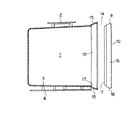
本実施形態における精密基板収納容器は、図1や図2に示すように、図示しない複数枚(例えば25枚)のウェーハを整列収納するポッド1と、このポッド1の開口正面をシール可能に開閉する中空の蓋体9と、この蓋体9の閉塞時に容器本体の開口正面内に蓋体9を案内して位置決めするガイド手段14と、蓋体9の閉塞時にその閉塞状態を維持するインナーロックタイプのロック手段18とを備えている。
【0017】
ポッド1は、図1に示すように、軽量性や成形性等に優れるポリカーボネイト等の合成樹脂を用いて透視可能な透明のフロントオープンボックスに成形されている。このポッド1は、変形しないよう十分な強度、剛性、及び寸法安定性が確保され、AGV(Auto Guided Vehicle)等からなる自動搬送装置の正常な作動を保障する。ポッド1の天井の中央部にはロボティックフランジ2が締結具を介して螺着され、このロボティックフランジ2が図示しない天井搬送機に把持されることにより、ポッド1が搬送される。
【0018】
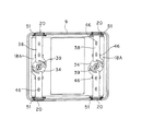
ポッド1の底面には、図2に示すように、円筒形を呈した複数の取付ボス3が所定の間隔をおいて突出成形され、この複数の取付ボス3には、平面略Y字形のボトムプレート4が締結具(図示せず)を介し着脱自在に装着されており、このボトムプレート4の前部両側と後部には、キネマティックカップリングからなる位置決め具5が締結具を介しそれぞれ着脱自在に装着されている(図1参照)。また、ポッド1の両外側面には、マニュアル運搬用のサイドハンドル6がそれぞれ着脱自在に装着される。
【0019】
ポッド1の内部両側には図1に部分的に示すように、相対向する一対のカラム7がそれぞれ着脱自在に立設され、ポッド1の内部背面には、図示しないリヤリテーナが着脱自在に立設固定されている。これら一対のカラム7の対向面とリヤリテーナの表面には、断面略U字形又は断面略V字形の支持スロット8が上下方向に並べて複数成形され、各支持スロット8にウェーハの周縁部が支持される。このような構成の一対のカラム7とリヤリテーナとは、複数枚のウェーハを水平に支持した状態で上下方向に所定のピッチで整列させるとともに、複数枚のウェーハの振動を有効に防止する。
【0020】
蓋体9は、図1や図2に示すように、ポッド1と同様の合成樹脂を用いて成形された表面プレート10と、表面が開口した略箱形の裏面プレート11とから構成され、この裏面プレート11の開口表面に表面プレート10が締結具を介して覆着されている。裏面プレート11の中央部には、リヤリテーナと相対向する同構成のフロントリテーナ12が着脱自在に装着固定され、裏面プレート11の周面には、枠形のシールガスケット13が突起や溝等を介し着脱自在に嵌合されている。
【0021】
シールガスケット13は、ポリオレフィン系やポリエスエル系の各種熱可塑性エラストマ、あるいはフッ素ゴムやシリコーンゴム等を用い、ガスケットとして成形される。また、好ましくは、ウェーハを汚染する有機成分の発生が少なく、JISに定められたK6301Aの測定方法による硬度80°以下の材料を使用して成形される。
【0022】
ガイド手段14は、図1や図2に示すように、ポッド1の開口正面の上下左右にそれぞれ傾斜成形され、ポッド1の内部(図2の左側)から開口正面の外方(図2の右側)に向かうにしたがい徐々に広がる第一の傾斜ガイド部15と、蓋体9の周面に傾斜成形されて蓋体9の裏面プレート11側から表面プレート10側に向かうにしたがい徐々に蓋体9の内部内方から外方に広がる第二の傾斜ガイド部16とから構成され、蓋体9の閉塞時に第一の傾斜ガイド部15に第二の傾斜ガイド部16が接触して位置決めするよう機能する。第一の傾斜ガイド部15の末端部はシール面17とされ、このシール面17にシールガスケット13が蓋体9の閉塞時に圧接されて変形し、このシールガスケット13の変形により、強固な高シール状態が確保される。
【0023】
さらに、ロック手段18は、図1に示すように、例えば、ポッド1の開口正面の上下における第一の傾斜ガイド部15にそれぞれ凹み成形される複数のクランプ穴19と、この複数のクランプ穴19に対応して蓋体9の上下における第二の傾斜ガイド部16にそれぞれ穿孔成形される複数の貫通孔20と、蓋体9の内部両側に軸支されて外部から表面プレート10の鍵孔21を介したアクセスで回転する一対の回転カム(回転体)と、各回転カムの表面外周の連結ピンに運動方向変換用の案内溝を介して遊嵌される上下一対のラッチプレート(動力伝達部材)とから構成されている。各ラッチプレートは、各種の金属や合成樹脂を用いて矩形に成形され、その先端部にはクランプ穴19に貫通孔20を介して係止する係止爪が突出成形されている。
【0024】
上記構成において、ウェーハを収納する場合には、先ず、ポッド1にスライスされた複数枚のウェーハがリヤリテーナ、及び一対のカラム7を介し整列収納され、ポッド1の開口正面内に蓋体9がシールガスケット13を介して嵌合されるとともに、複数枚のウェーハにフロントリテーナ12がそれぞれ圧接され、ロック手段18が図示しない加工装置のドア開閉装置(開閉機構)に施錠操作される。
この際、蓋体9は、上下左右の第一、第二の傾斜ガイド部15、16のガイド作用により、上下前後左右の位置がシール状態で高精度に定められ、がたつきや位置ずれを生じることがない。
【0025】
ロック手段18が施錠操作されると、各回転カムが回転して各ラッチプレートを蓋体9の内部内方向から内部外方向に突出させ、各ラッチプレートの係止爪が貫通孔20から突出して各クランプ穴19に嵌合係止し、ポッド1の開口正面に蓋体9が気密状態で安定、かつ強固に嵌合覆着される。
【0026】
上記構成によれば、傾いた第一、第二の傾斜ガイド部15、16が案内誘導作用を発揮するので、繰り返し使用される蓋体9のがたつきや位置ずれを簡易な構成で有効に防止することができる。したがって、蓋体9の嵌合時にクランプ穴19、貫通孔20、及び係止爪が位置ずれしたり、蓋体9の施錠が困難となることがない。さらに、ポッド1の開口正面と蓋体9のエッジ部とが擦れてパーティクル等の汚染物が発生するのをきわめて有効に抑制防止することが可能となる。
【0027】
ところで、図3ないし図5は本発明の主要な実施形態を示すもので、この場合には、ガイド手段14を、ポッド1の開口正面における上下左右の中央部にそれぞれ凹み成形される断面略U字形の嵌合凹部22と、蓋体9の周面における上下左右の中央部にそれぞれ突出成形される嵌合リブ23とから構成し、これら複数の嵌合凹部22と嵌合リブ23とを蓋体9の閉塞時に相互に嵌合させるようにしている。
【0028】
各嵌合凹部22と各嵌合リブ23とは、それぞれ略台形に成形され、その接触面がポッド1の背面側方向(図2の左側)から開口正面方向に向かうにしたがい徐々にポッド1の内部内方から外方に広がるよう傾斜成形されている(図3及び図4参照)。各嵌合リブ23は、その高さが0.1mm〜10mm、好ましくは0.3mm〜2.0mmに設定され、幅が3mm〜100mm、好ましくは10mm〜50mmに設定されている。そして、これら数値に対応して各嵌合凹部22が成形されている。その他の部分については、上記実施形態と同様であるので説明を省略する。
【0029】
本実施形態においても上記実施形態と同様の作用効果が期待でき、しかも、蓋体9の閉塞時に嵌合凹部22と嵌合リブ23とが嵌合して位置合わせするので、蓋体9の上下前後左右の位置がシール状態でさらに高精度に定められることは明らかである。
【0030】
なお、本実施形態では嵌合凹部22を断面略U字形としたが、何らこれに限定されるものではなく、嵌合凹部22を断面略C字形、コ字形、又は半円筒形等とし、これらの形状に対応させて嵌合リブ23を成形しても良い。また、第一の傾斜部に嵌合凹部22を、第二の傾斜部に嵌合リブ23をそれぞれ成形しても良い。さらに、ポッド1の開口正面に嵌合凹部22を、蓋体9の周面に嵌合リブ23をそれぞれ成形したものを示したが、ポッド1の開口正面に嵌合リブ23を、蓋体9の周面に嵌合凹部22をそれぞれ成形することも可能である。
【0031】
次に、図6及び図7は本発明の第二の発明の実施形態を示すもので、この場合には、ガイド手段14を、第一の傾斜ガイド部15、第二の傾斜ガイド部16、及び摩擦低減機能を有する複数のプランジャ部材24から構成し、この複数のプランジャ部材24を蓋体9の第二の傾斜ガイド部16に埋設して蓋体9の閉塞時に第一の傾斜ガイド部15に圧接するようにしている。
【0032】
各プランジャ部材24は、蓋体9の内部外周に埋設される有底筒形のケース25を備え、このケース25には、表面が滑らかに湾曲したプランジャ26がコイルスプリング27を介して進退動可能、出没可能に弾発支持されている。各プランジャ26は、蓋体9の非閉塞時に第二の傾斜ガイド部16から0.1mm〜10mm程度露出するようコイルスプリング27に支持されている。その他の部分については、上記実施形態と同様であるので説明を省略する。
【0033】
上記構成において、ポッド1の開口正面に蓋体9をシールガスケット13を介して密嵌する場合、第一の傾斜ガイド部15に第二の傾斜ガイド部16が案内されて嵌合していくと、第一の傾斜ガイド部15に接触するプランジャ部材24のプランジャ26が徐々にケース25内に押し込まれて埋没する。
【0034】
本実施形態においても上記実施形態と同様の作用効果が期待でき、しかも、第一の傾斜ガイド部15に表面の丸まったプランジャ26が小面積で接触、又は点接触するので、位置決め時の摺動が向上し、発塵が大幅に減少してパーティクル等の汚染物が発生するのをきわめて有効に抑制防止することが可能になる。
【0035】
次に、図8は本発明の第二の発明の他の実施形態を示すもので、この場合には、ガイド手段14を、第一の傾斜ガイド部15、第二の傾斜ガイド部16、及び摩擦低減機能を有する複数のローラ部材28から構成し、この複数のローラ部材28を蓋体9の第二の傾斜ガイド部16に埋設して蓋体9の閉塞時に第一の傾斜ガイド部15に圧接するようにしている。
【0036】
各ローラ部材28は、蓋体9の内部外周に埋設される有底筒形のケース29を備え、このケース29の内部には、コイルスプリング30が内蔵されるとともに、このコイルスプリング30の先端部には、回転ローラ31がガイドピン32を介し進退動可能・出没可能に弾発支持されている。各回転ローラ31は、蓋体9の非閉塞時に第二の傾斜ガイド部16から0.1mm〜10mm程度露出するようコイルスプリング30に回転可能に支持されている。その他の部分については、上記実施形態と同様であるので説明を省略する。
【0037】
上記構成において、ポッド1の開口正面に蓋体9をシールガスケット13を介して密嵌する場合、第一の傾斜ガイド部15に第二の傾斜ガイド部16が案内されて嵌合していくと、第一の傾斜ガイド部15に摺接するローラ部材28の回転ローラ31が徐々にケース29内に押し込まれて埋没する。
【0038】
本実施形態においても上記実施形態と同様の作用効果が期待でき、しかも、第一の傾斜ガイド部15に回転ローラ31が回転しながらころがり接触するので、位置決め時の摺動が著しく向上し、摩擦抵抗が大幅に減少してパーティクル等の汚染物の発生を著しく抑制防止することが可能になる。
【0039】
なお、上記実施形態では接触面積の少ないプランジャ26や回転ローラ31を使用したものを示したが、何らこれに限定されるものではない。同様の作用効果が期待できるものであれば、プランジャ26や回転ローラ31以外のものを使用しても良い。また、コイルスプリング27、30を使用したが、板ばね等の各種のばね、ゴム弾性体、又はフレキシブルなプラスチック部材等を使用することもできる。また、プランジャ部材24やローラ部材28を蓋体9の内部外周に埋設したものを示したが、ポッド1の第一の傾斜ガイド部15に埋設しても良い。
【0040】
また、上記諸実施形態では回転カムの表面外周の連結ピンに一対のラッチプレートを案内溝を介し遊嵌したものを示したが、回転カムの代わりにカム部を有しない回転プレートを使用し、この回転プレートの表面外周の連結ピンに一対のラッチプレートを揺動ピンを介し連結しても良い。また、ロック手段18を後述するロック手段18Aとすることも可能である。さらに、上記諸実施形態ではインナーロックタイプのロック手段18を示したが、各種のアウターロックタイプのロック手段を採用しても良い。例えば、従来同様、ポッド1の開口正面の外周部に揺動可能に複数の係止片を、蓋体9の周面には複数の凸部をそれぞれ成形することも可能である。
【0041】
上記実施形態のロック手段18は、上記構成に限定されるものではなく、以下の構成を有するロック手段18Aに変更することができる。
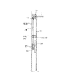
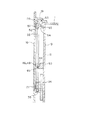
この場合のロック手段18Aは、図9ないし図19に示すように、ポッド1の開口正面の内周面上下に成形される複数のクランプ穴19と、蓋体9の周面上下に成形されて複数のクランプ穴19に対向する複数の貫通孔20と、蓋体9の内部両側の中央に軸支されて外部からのアクセス操作で回転する一対の回転プレート34と、各回転プレート34の回転で蓋体9の内外方向に直線的にスライドする複数の動力伝達プレート38と、各動力伝達プレート38のスライドを案内するガイド部材46と、各動力伝達プレート38の突出時に各貫通孔20から突出して各クランプ穴19に嵌入し、各動力伝達プレート38の復帰時には各貫通孔20内に復帰する合成樹脂製のクランプ部材51とから構成される。
【0042】
蓋体9は、図11や図13に示すように、ポッド1と同様の合成樹脂を用いて成形された表面プレート10と、表面が開口した略箱形の裏面プレート11とから構成され、この裏面プレート11の開口表面に表面プレート10が締結具を介して覆着されている。表面プレート10の両側には鍵孔21がそれぞれ穿孔成形され、各鍵孔21に、加工装置のドア開閉装置のアタッチメント33が挿通される。また、裏面プレート11の中央部には、フロントリテーナ12が着脱自在に装着固定され、裏面プレート11の外周には、枠形のシールガスケット13が突起や溝等を介し着脱自在に嵌合されている。
【0043】
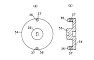
各回転プレート34は、図14や図15に示すように、ポリアセタール樹脂等を用いて円板形に成形され、その表面の中心部には、有底円筒形の操作突部35が突出成形されており、この操作突部35内に鍵孔21を貫通したアタッチメント33が着脱自在に嵌挿される(図16参照)。各回転プレート34の表面外周には、円柱形を呈した一対の連結ピン36が突出成形され、各連結ピン36には、摩擦低減機能を有する円筒形の回転ローラ37が必要に応じ回転可能に嵌入される。
【0044】
なお、ドア開閉装置と各回転プレート34との接続位置や寸法は、SEMI規格でポッド1のサイズ毎に定められている。例えば、300mmウェーハ用の蓋体9の規格は、SEMI規格のE62に対応して定められている。
【0045】
複数の動力伝達プレート38は、図9ないし図13に示すように、ポリアセタール樹脂等を用いて基本的には長方形の板形に成形され、長手方向の中心軸が回転プレート34の中心を通るよう、蓋体9の内部両側の上下にそれぞれスライド可能に配置されている。各動力伝達プレート38の末端部は側方に向け略半円弧形に湾曲成形されて回転プレート34の表面外周の一部を被覆し、連結ピン36又は回転ローラ37に嵌入される案内溝39が穿孔成形されている。
【0046】
案内溝39は、連結ピン36の軌跡と略等しい曲率の第一の案内溝40と、連結ピン36の軌跡よりも大きな曲率の第二の案内溝41と、これら第一、第二の案内溝40、41を接続する変曲部42とから構成されている。このように成形された各第一の案内溝40は、蓋体9の内外方向(図9の上下方向)に各動力伝達プレート38を直線運動させるよう機能する。また、各第二の案内溝41は、各動力伝達プレート38が立体的な経路で直線運動するよう案内する。
【0047】
各動力伝達プレート38の中央付近には、小判形を呈した複数のガイド長孔43が長手方向に所定の間隔をおいて穿孔成形されている。各動力伝達プレート38の左右両側部には、ガイドピン44がそれぞれ突出成形され、各ガイドピン44には、摩擦低減機能を有する円筒形の回転ローラ45が必要に応じ回転可能に嵌入される(図18参照)。
【0048】
ガイド部材46は、裏面プレート11の内面に突出成形されて複数のガイド長孔43にそれぞれ遊嵌する第一のガイド47と、第二のガイド49とから構成されている。第一のガイド47は、円柱形に成形され、摩擦低減機能を有する回転ローラ48が必要に応じ回転可能に嵌入される。また、第二のガイド49は、表面プレート10と裏面プレート11の内部対向面にそれぞれ突出成形される複数対の対向ガイド50を備えている。各一対の対向ガイド50の対向湾曲面は、各ガイドピン44又は各回転ローラ45を挟んで直線運動する動力伝達プレート38が蓋体9の表裏方向(図18の左右方向)に立体的に運動する際のガイドとして機能する。
【0049】
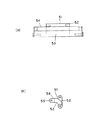
さらに、クランプ部材51は、図17ないし図19(a)、(b)に示すように、動力伝達プレート38の先端部にピンを介して軸支される回転可能な第一のアーム52と、この第一のアーム52の先端部と末端部が一体化した第二のアーム53とから構成されている。第二のアーム53は、略L字形に屈曲成形されてその先端部が第一のアーム52と略直角方向に指向し、この先端部がクランプ穴19用の嵌入押さえ部54とされており、この嵌入押さえ部54には、クランプ穴19内に摺接する円筒形の回転ローラ55がピンを介して軸支されている。第二のアーム53の末端部は、蓋体9の内部外周における貫通孔20の近傍にピンを介して軸支され、第二のアーム53、換言すれば、クランプ部材51を蓋体9の内外方向に回転させる。その他の部分については、上記実施形態と同様であるので説明を省略する。
【0050】
上記構成において、ウェーハを収納する場合には、先ず、ポッド1にスライスされた複数枚のウェーハがリヤリテーナ、及び一対のカラム7を介し整列収納され、ポッド1の開口正面に蓋体9がシールガスケット13を介して嵌合されるとともに、複数枚のウェーハにフロントリテーナ12がそれぞれ圧接され、ロック手段18Aが加工装置のドア開閉装置に施錠操作される。
【0051】
すると、回転プレート34の操作突部35にアタッチメント33が挿入されて回転プレート34を時計方向に90°回転させ、各動力伝達プレート38がガイド部材46に案内されつつ蓋体9の内部内方向から内部外方向に直線立体的に突出して第一のアーム52を揺動させ、末端部を中心として第二のアーム53が蓋体9の内部外方向に揺動して貫通孔20から嵌入押さえ部54を露出させ、この嵌入押さえ部54の回転ローラ37がクランプ穴19に嵌合係止して蓋体9の固定状態を強固に維持する(図12、図13、及び図17参照)。
【0052】
この際、各第二のアーム53の嵌入押さえ部54は、梁の機能を発揮する各動力伝達プレート38と略一直線となった状態でクランプ穴19に嵌合係止する(図13参照)。したがって、回転プレート34に加わった動力がクランプ部材51に一直線、かつ円滑に伝達される。また、嵌入押さえ部54は、円運動して貫通孔20に接触することなく露出する。
【0053】
次いで、収納、保管、又は輸送されたウェーハを処理したい場合、先ず、ロック手段18Aが加工装置のドア開閉装置に解錠操作され、回転プレート34の操作突部35にアタッチメント33が挿入されて回転プレート34を反時計方向に90°回転させ、各動力伝達プレート38がガイド部材46に案内されつつ蓋体9の内部外方向から内部内方向に直線立体的に復帰して第一のアーム52を復帰揺動させる。この第一のアーム52の復帰揺動により、第二のアーム53が蓋体9の内部内方向に揺動して貫通孔20内に嵌入押さえ部54を復帰させ、蓋体9が取り外し可能な状態となる(図10及び図11参照)。この際、嵌入押さえ部54は、貫通孔20に接触することなく円運動して復帰する。
【0054】
こうして蓋体9が開放可能となったら、ポッド1から蓋体9が真空吸着により取り外され、その後、ポッド1の下方から複数枚のウェーハが順次取り出され、ウェーハに所定の処理が施される。
【0055】
上記構成によれば、施錠操作時に第二のアーム53の嵌入押さえ部54が動力伝達プレート38と略一直線の状態で蓋体9を固定するので、従来に比べ安定した大きな係止力で蓋体9を固定することができる。したがって、各動力伝達プレート38に動力が局部的に作用して撓んだり、この撓みに伴う係止力の減少を実に有効に防止することができ、ポッド1の全開口正面を長期にわたり十分、かつ均一にシールすることが可能になる。また、高剛性の合成樹脂を使用して各動力伝達プレート38を成形することができるので、金属部品を軽減、あるいは省略することができ、洗浄時等の金属イオン発生によるウェーハの汚染の抑制防止も期待できる。
【0056】
また、接触部分に回転ローラ37、45、48、55がそれぞれ軸支されているので、摩擦抵抗が著しく減少し、樹脂粉の発生を抑制防止することができる。さらに、第二のアーム53が貫通孔20の近傍に軸支されているので、蓋体9の厚さを必要最小限に薄くすることが可能になる。
【0057】
なお、上記実施形態のロック手段18Aの構成要素は適宜増減変更しても良い。また、各動力伝達プレート38の左右両側部にガイドピン44をそれぞれ突出成形したが、各動力伝達プレート38の左右両側部にカムフロアをそれぞれ設けても良い。また、第二のアーム53を略L字形に屈曲成形したが、同様の作用効果が期待できるものであれば、J字形等に適宜屈曲成形することが可能である。また、第一のアーム52の先端部と第二のアーム53の末端部とを一体化したが、同様の作用効果が期待できるものであれば、第二のアーム53に第一のアーム52の先端部を回転可能に取り付けることもできる。
【0058】
さらに、上記実施形態では第二のアーム53の嵌入押さえ部54に回転ローラ55を軸支させたものを示したが、何らこれに限定されるものではない。例えば、回転ローラ55の先端部をばね等の弾性部材で保持し、外力作用時に蓋体9の内部に後退するよう構成する。そして、蓋体9の周面から回転ローラ55を0.1mm〜10mm、好ましくは0.3mm〜2mm程度突出させ、ポッド1の開口正面に蓋体9を嵌合する際、回転ローラ55をガイドとして使用することも可能である。
【0059】
【発明の効果】
以上のように本発明によれば、容器本体の開口正面から取り外した蓋体を再度容器本体の開口正面に装着する際の蓋体のがたつきを防止し、このがたつきに伴う蓋体の施錠の困難化や汚染物の発生を抑制防止することができるという効果がある。
また、ロック手段を施錠操作すれば、容器本体の開口正面に蓋体を気密状態で安定、かつ強固に嵌め合わせることができる。
【図面の簡単な説明】
【図1】本発明の第一の発明に係る精密基板収納容器の実施形態を示す全体斜視説明図である。
【図2】本発明の第一の発明に係る精密基板収納容器の実施形態を示す断面側面図である。
【図3】本発明の第一の発明に係る精密基板収納容器の実施形態を示す正面説明図である。
【図4】本発明の第一の発明に係る精密基板収納容器の実施形態を示す要部断面説明図である。
【図5】本発明の第一の発明に係る精密基板収納容器の実施形態を示す要部斜視図である。
【図6】本発明の第二の発明に係る精密基板収納容器の実施形態を示す断面側面図である。
【図7】図6の要部拡大断面図である。
【図8】本発明の第二の発明に係る精密基板収納容器の他の実施形態を示す要部断面説明図である。
【図9】本発明に係る精密基板収納容器の実施形態における他のロック手段を示す正面説明図である。
【図10】本発明に係る精密基板収納容器の実施形態における他のロック手段の蓋体開放状態を示す説明図である。
【図11】図10のXI−XI線断面説明図である。
【図12】本発明に係る精密基板収納容器の実施形態における他のロック手段の蓋体閉塞状態を示す説明図である。
【図13】図12のXIII−XIII線断面説明図である。
【図14】本発明に係る精密基板収納容器の実施形態における他のロック手段の回転プレートを示す図で、(a)図は平面図、(b)図は(a)図の断面図である。
【図15】本発明に係る精密基板収納容器の実施形態における他のロック手段の回転ローラ付き回転プレートを示す図で、(a)図は平面図、(b)図は(a)図の断面図である。
【図16】回転プレートに加工装置の開閉機構が挿入された状態を示す断面説明図である。
【図17】本発明に係る精密基板収納容器の実施形態における他のロック手段の閉塞時のクランプ部材を示す要部拡大断面図である。
【図18】本発明の第二の発明に係る精密基板収納容器の実施形態における蓋体、回転プレート、動力伝達プレート、ガイド部材、及びクランプ部材を示す要部拡大断面図である。
【図19】本発明に係る精密基板収納容器の実施形態における他のロック手段のクランプ部材を示す図で、(a)図は平面図、(b)図は(a)図の側面図である。[0001]
TECHNICAL FIELD OF THE INVENTION
The present invention relates to a precision substrate storage container used for storage, storage, processing in a process, or transportation of a precision substrate made of an aluminum disk, a semiconductor wafer, or a mask glass, and more specifically, for processing a semiconductor wafer. The present invention relates to an improvement in a container body, a lid, and a lock mechanism of a precision substrate storage container that can be connected to a device having a standardized mechanical interface to be used.
[0002]
[Prior art]
Although not shown, a conventional precision substrate storage container includes a pod (Pod) for aligning and storing a plurality of semiconductor wafers (hereinafter abbreviated as "wafer"), and a hollow lid for opening and closing the opening surface of the pod in a sealable manner. And a lock means for maintaining the closed state when the lid is closed.
[0003]
Locking means are classified into an inner lock type and an outer lock type. The lock means of the inner lock type includes a plurality of clamp holes that are respectively recessed above and below the inner peripheral surface of the opening surface of the pod, and holes are formed on the upper and lower peripheral surfaces of the lid corresponding to the plurality of clamp holes. A plurality of through-holes, a rotating cam pivotally supported at the center of the inside of the lid and rotating by external access, and is loosely fitted to a connecting pin on the outer periphery of the surface of the rotating cam via a guide groove for converting the direction of movement. And a pair of upper and lower latch plates.
Each latch plate is formed of metal so as to ensure high rigidity, and a locking claw that locks through a through hole in a clamp hole protrudes from a tip portion thereof.
[0004]
On the other hand, the latter outer lock type locking means includes a plurality of locking pieces swingably formed on the outer peripheral portion of the opening surface of the pod, and a plurality of convex portions protrudingly formed on the peripheral surface of the lid. It is composed of The plurality of locking pieces and the projection function to lock when the lid is closed.
[0005]
In the above configuration, when storing, storing, or transporting wafers, first, a plurality of wafers are sequentially stored in a pod, and a lid is fitted in a sealing state in an opening surface of the pod. For example, a rotating cam is rotated in one direction to perform a locking operation by a door opening / closing device of a processing apparatus that does not perform processing. Then, each latch plate linearly protrudes from the inside inside to the outside outside of the lid, the locking claw is locked in the clamp hole, and the fixed state of the lid is maintained.
[0006]
On the other hand, when it is desired to process the stored, stored, or transported wafer, first, the rotating cam is rotated in the other direction by the door opening / closing device of the processing apparatus to perform the unlocking operation. Then, each latch plate returns linearly from the inside to the outside of the lid to the inside of the lid, the locking claw is released from the clamp hole, and the lid can be opened. When the lid can be opened in this way, the lid is removed from the pod by vacuum suction or the like, and then a plurality of wafers are sequentially taken out from below the pod, and the wafer is subjected to a predetermined process.
[0007]
Related prior art documents of this type include JP-A-9-88398, 8-340043, JP-T4-505234, and 7-504536.
[0008]
[Problems to be solved by the invention]
As described above, the conventional precision substrate storage container is configured such that the lid is simply fitted or simply removed from the opening surface of the pod, and the backlash of the repeatedly used lid is not considered at all. Did not. In addition, the displacement between the lid and the pod due to the variation in the repetition accuracy of the operation of the processing device that holds the lid when the lid is removed has not been considered.
However, if the lid rattles or the fitting position of the lid is incorrect, the clamp hole, the through hole, and the locking claw are displaced when the lid is fitted, making it difficult to lock the lid, There is a problem in that the opening surface of the pod and the edge of the lid rub against each other to generate contaminants such as particles.
[0009]
The present invention has been made in view of the above problems, and prevents rattling of a lid when the lid removed from the front of the opening of the container body is again mounted on the front of the opening of the container body, and locks the lid. It is an object of the present invention to provide a precision substrate storage container capable of facilitating prevention of generation of contaminants.
[0011]
[Means for Solving the Problems]
In the present invention, in order to achieve the above object, a container body of a front open box type for accommodating a precision substrate, a lid for opening and closing the opening front of the container body in a sealable manner, and a container body for closing the lid when closing the lid. Guide means for guiding and positioning the lid in the front of the opening, and locking means for fixing the lid in a closed state,
The guide means includes a fitting recess formed in at least one of the lower part of the opening front of the container body and at least the lower part of the lid peripheral surface, and the at least lower part of the container main body opening front and at least the lower part of the lid peripheral surface. Formed on one of the other sides, and formed with a fitting convex portion that fits into the fitting concave portion when the lid is closed, and a contact surface of the fitting concave portion and the fitting convex portion is formed from the inside of the container body to the outside of the opening front. Incline to spread as you go,
A locking means, a clamp hole formed in the inner periphery of the opening front of the container body, a rotating body built in the lid and rotated by an external operation, and an inward / outward direction inside the lid based on the rotation of the rotating body. A power transmission member that projects the tip from the through hole provided on the peripheral surface of the lid when entering and fits into the clamp hole, and returns the projected tip to the through hole of the lid when retracted. It is characterized by having comprised.
[0012]
Further, in the present invention, in order to achieve the above object, a front open box type container main body that stores a precision substrate, a lid that opens and closes the opening front of the container main body in a sealable manner, and when the lid is closed. Guide means for guiding and positioning the lid within the opening front of the container body, and locking means for fixing the lid in a closed state,
A guide means is formed at least at a lower portion of the front of the opening of the container body, and is formed at least at a lower portion of the peripheral surface of the lid, and a first inclined guide portion which is inclined so as to expand from the inside of the container body toward the outside of the opening front. While being inclined to spread from the back side to the front side of the lid, the second inclined guide portion that contacts the first inclined guide portion when the lid is closed, and has a friction reducing function, A friction reducing member which is elastically supported so as to be able to protrude and retreat to one of the first and second inclined guide portions and which comes into contact with the other under pressure when closing the lid,
A locking means, a clamp hole formed in the inner periphery of the opening front of the container body, a rotating body built in the lid and rotated by an external operation, and an inward / outward direction inside the lid based on the rotation of the rotating body. A power transmission member that projects the tip from the through hole provided on the peripheral surface of the lid when entering and fits into the clamp hole, and returns the projected tip to the through hole of the lid when retracted. It is characterized by having comprised.
[0013]
Here, the container main body and the lid in the claims can be molded using a resin such as polycarbonate, acrylonitrile, polybutylene terephthalate, PEEK, PEI, PES, or polypropylene. The container main body and the lid can be subjected to antistatic treatment and coloring as required. When used as a 300 mm wafer carrier, the appearance of the container body can be configured substantially in accordance with SEMI standard E47.1-0097 and a modified ballot. In addition, precision substrates include at least one (eg, 13 or 25) aluminum disks, liquid crystal cells, quartz glass, and semiconductor wafers (eg, silicon wafers) used in manufacturing fields of information communication, electricity, electronics, semiconductors, and the like. Wafer, etc.) or a mask substrate. When the precision substrate is a semiconductor wafer, a semiconductor wafer having a large diameter (for example, 200 mm to 300 mm or more) is included.
[0014]
The first inclined guide portion may be formed at a minimum at the lower portion of the front of the opening of the container body, and may be formed at the upper portion, one side, and / or the other side of the front of the opening of the container body. Similarly, the second inclined guide portion may be formed at a minimum at the lower portion of the lid peripheral surface, and may be formed at the upper portion, one side portion, and / or the other side portion of the lid peripheral surface. Further, the rotating body and the power transmission member constituting the locking means can be made of a resin material having good slidability and sufficient strength. For example, use of a polyacetal resin, PEEK, polycarbonate, PPS, polybutylene terephthalate, PEI, or a fluororesin can be considered. Further, various resins containing a fluororesin and having improved slidability can also be used. Further, in order to improve the mechanical strength, a filler such as glass fiber, glass beads, or talc can be added to the resin, or a metal component can be inserted into the resin to be molded.
[0015]
According to the present invention, when the lid is fitted in a sealed state in front of the opening of the container body, the lid is in a sealed state in the upper, lower, left and right positions by the guiding action of the guide means provided on the container body and the lid. Is determined accurately. In addition, when the locking means is operated to lock, the rotating body rotates to cause the power transmission member to protrude from the inside to the outside of the lid, and the front end of the power transmission member fits into the clamp hole of the container body.
Further, when the second inclined guide portion of the lid is guided by the first inclined guide portion of the container body and the lid is fitted in a sealed state, the friction reducing member is moved to the first or second inclined guide. It comes into contact with the part with a small area, point contact, or rolling contact, and is pushed back into the lid or the container body.
[0016]
BEST MODE FOR CARRYING OUT THE INVENTION
Hereinafter, an embodiment of the first invention of the present invention will be described with reference to the drawings,The inventionIs not limited to the following embodiments.
As shown in FIGS. 1 and 2, the precision substrate storage container according to the present embodiment includes a
[0017]
As shown in FIG. 1, the
[0018]
As shown in FIG. 2, a plurality of cylindrical mounting bosses 3 are formed on the bottom surface of the
[0019]
As shown in FIG. 1, a pair of opposed columns 7 are detachably provided on both sides of the inside of the
[0020]
As shown in FIGS. 1 and 2, the
[0021]
The
[0022]
As shown in FIGS. 1 and 2, the guide means 14 is formed to be inclined at the upper, lower, left and right sides of the front of the opening of the
[0023]
Further, as shown in FIG. 1, for example, the locking means 18 includes a plurality of clamp holes 19 formed in the first
[0024]
In the above configuration, when storing wafers, first, a plurality of wafers sliced into the
At this time, the upper, lower, left, right, and upper positions of the
[0025]
When the locking means 18 is operated to lock, each rotating cam rotates to cause each latch plate to protrude from the inside inside to the outside outside of the
[0026]
According to the above configuration, since the inclined first and second
[0027]
3 to 5 show main embodiments of the present invention.In this case, the guide means 14 is provided with a
[0028]
Each of the
[0029]
In this embodiment, the same operation and effect as those of the above embodiment can be expected. In addition, when the
[0030]
In the present embodiment, the fitting
[0031]
Next, FIG. 6 and FIG.Second Embodiment of the InventionIn this case, the guide means 14 comprises a first
[0032]
Each
[0033]
In the above configuration, when the
[0034]
In this embodiment, the same operation and effect as those in the above embodiment can be expected. Further, since the
[0035]
Next, FIG.Another embodiment of the second inventionIn this case, the guide means 14 is composed of a first
[0036]
Each
[0037]
In the above configuration, when the
[0038]
In this embodiment, the same operation and effect as those of the above embodiment can be expected. In addition, since the rolling
[0039]
In the above embodiment, the
[0040]
Further, in the above embodiments, the pair of latch plates are loosely fitted to the connection pins on the outer periphery of the surface of the rotary cam via the guide grooves, but a rotary plate having no cam portion is used instead of the rotary cam, A pair of latch plates may be connected to connecting pins on the outer periphery of the surface of the rotating plate via swing pins. Further, the locking means 18 may be a locking means 18A described later. Further, in the above embodiments, the inner lock type locking means 18 is shown, but various outer lock type locking means may be employed. For example, as in the conventional case, it is also possible to form a plurality of locking pieces on the outer peripheral portion of the front face of the opening of the
[0041]
The lock unit 18 of the above embodiment is not limited to the above configuration, but can be changed to a
As shown in FIGS. 9 to 19, the locking means 18 </ b> A in this case includes a plurality of clamp holes 19 formed above and below the inner peripheral surface in front of the opening of the
[0042]
As shown in FIGS. 11 and 13, the
[0043]
As shown in FIGS. 14 and 15, each
[0044]
The connection position and dimensions between the door opening / closing device and each
[0045]
The plurality of
[0046]
The
[0047]
In the vicinity of the center of each
[0048]
The
[0049]
Further, as shown in FIGS. 17 to 19 (a) and (b), the
[0050]
In the above configuration, when storing wafers, first, a plurality of wafers sliced in the
[0051]
Then, the
[0052]
At this time, the
[0053]
Next, when it is desired to process the stored, stored, or transported wafer, first, the locking means 18A is unlocked by the door opening / closing device of the processing device, and the
[0054]
When the
[0055]
According to the above configuration, the
[0056]
In addition, since the
[0057]
The components of the locking means 18A of the above embodiment may be appropriately increased or decreased. Although the guide pins 44 are formed on the left and right sides of each
[0058]
Further, in the above-described embodiment, the
[0059]
【The invention's effect】
As described above, according to the present invention, it is possible to prevent the lid from rattling when the lid removed from the front opening of the container main body is again attached to the front opening of the container main body, and the lid accompanying the rattling is prevented. This has the effect of making it difficult to lock and preventing the occurrence of contaminants.
In addition, if the locking means is operated by locking, the lid can be stably and firmly fitted to the front of the opening of the container body in an airtight state.
[Brief description of the drawings]
FIG. 1 is an overall perspective explanatory view showing an embodiment of a precision substrate storage container according to the first invention of the present invention.
FIG. 2 is a sectional side view showing an embodiment of the precision substrate storage container according to the first invention of the present invention.
FIG. 3 of the present invention.First inventionIt is an explanatory front view showing an embodiment of a precision substrate storage container according to the present invention.
FIG. 4 of the present invention.First inventionIt is principal part sectional explanatory drawing which shows embodiment of the precision substrate storage container concerning this.
FIG. 5 of the present invention.First inventionIt is a principal part perspective view which shows embodiment of the precision substrate storage container concerning this.
FIG. 6 of the present invention.Second invention1 is a sectional side view showing an embodiment of a precision substrate storage container according to the present invention.
FIG. 7 is an enlarged sectional view of a main part of FIG. 6;
FIG. 8 of the present invention.Second inventionIt is principal part sectional explanatory drawing which shows other embodiment of the precision substrate storage container concerning this.
FIG. 9 is an explanatory front view showing another locking means in the embodiment of the precision substrate storage container according to the present invention.
FIG. 10 is an explanatory view showing an open state of a lid of another locking means in the embodiment of the precision substrate storage container according to the present invention.
11 is an explanatory cross-sectional view taken along line XI-XI in FIG. 10;
FIG. 12 is an explanatory view showing a closed state of a lid of another locking means in the embodiment of the precision substrate storage container according to the present invention.
FIG. 13 is an explanatory sectional view taken along line XIII-XIII in FIG. 12;
14A and 14B are views showing a rotation plate of another locking means in the embodiment of the precision substrate storage container according to the present invention, wherein FIG. 14A is a plan view and FIG. 14B is a cross-sectional view of FIG. .
15A and 15B are views showing a rotating plate with a rotating roller of another locking means in the precision substrate storage container according to the embodiment of the present invention, wherein FIG. 15A is a plan view and FIG. FIG.
FIG. 16 is an explanatory sectional view showing a state in which the opening / closing mechanism of the processing device is inserted into the rotating plate.
FIG. 17 is an enlarged sectional view of a main part showing a clamp member when another lock means is closed in the embodiment of the precision substrate storage container according to the present invention.
FIG. 18 is an enlarged sectional view of a main part showing a lid, a rotary plate, a power transmission plate, a guide member, and a clamp member in the embodiment of the precision substrate storage container according to the second invention of the present invention.
19A and 19B are diagrams showing a clamp member of another locking means in the embodiment of the precision substrate storage container according to the present invention, wherein FIG. 19A is a plan view and FIG. 19B is a side view of FIG. .
Claims (2)
ガイド手段を、容器本体の開口正面の少なくとも下部と蓋体周面の少なくとも下部のいずれか一方に形成される嵌合凹部と、容器本体の開口正面の少なくとも下部と蓋体周面の少なくとも下部のいずれか他方に形成され、蓋体の閉塞時に嵌合凹部に嵌まる嵌合凸部とから構成し、これら嵌合凹部と嵌合凸部の接触面を容器本体の内部から開口正面外方に向かうにしたがい広がるよう傾斜させ、
ロック手段を、容器本体の開口正面内周に形成されるクランプ穴と、蓋体に内蔵されて外部からの操作により回転する回転体と、この回転体の回転に基づいて蓋体内部の内外方向に進退動し、進出時には蓋体の周面に設けられた貫通孔から先端部を突出させてクランプ穴に嵌め、後退時には突出した先端部を蓋体の貫通孔に復帰させる動力伝達部材とから構成したことを特徴とする精密基板収納容器。A front open box type container main body that stores precision substrates, a lid that opens and closes the front of the container main body in a sealable manner, and guides and positions the lid within the front opening of the container main body when the lid is closed. And a locking means for fixing the lid in a closed state, a precision substrate storage container comprising:
The guide means includes a fitting recess formed in at least one of the lower part of the opening front of the container body and at least the lower part of the lid peripheral surface, and the at least lower part of the container main body opening front and at least the lower part of the lid peripheral surface. Formed on one of the other sides, and formed with a fitting convex portion that fits into the fitting concave portion when the lid is closed, and a contact surface of the fitting concave portion and the fitting convex portion is formed from the inside of the container body to the outside of the opening front. Incline to spread as you go,
A locking means, a clamp hole formed in the inner periphery of the opening front of the container body, a rotating body built in the lid and rotated by an external operation, and an inward / outward direction inside the lid based on the rotation of the rotating body. A power transmission member that makes the tip end protrude from the through hole provided on the peripheral surface of the lid at the time of advancement, fits into the clamp hole, and returns the protruded tip to the through hole of the lid at the time of retreat. A precision substrate storage container characterized by being constituted.
ガイド手段を、容器本体の開口正面の少なくとも下部に形成され、容器本体の内部から開口正面外方に向かうにしたがい広がるよう傾斜する第一の傾斜ガイド部と、蓋体周面の少なくとも下部に形成されるとともに、蓋体の裏面側から表面側に向かうにしたがい広がるよう傾斜し、蓋体の閉塞時に第一の傾斜ガイド部に接触する第二の傾斜ガイド部と、摩擦低減機能を有し、第一、第二の傾斜ガイド部のいずれか一方に出没可能に弾性支持されて他方に蓋体の閉塞時に圧力作用状態で接触する摩擦低減部材とから構成し、
ロック手段を、容器本体の開口正面内周に形成されるクランプ穴と、蓋体に内蔵されて外部からの操作により回転する回転体と、この回転体の回転に基づいて蓋体内部の内外方向に進退動し、進出時には蓋体の周面に設けられた貫通孔から先端部を突出させてクランプ穴に嵌め、後退時には突出した先端部を蓋体の貫通孔に復帰させる動力伝達部材とから構成したことを特徴とする精密基板収納容器。A front open box type container main body that stores precision substrates, a lid that opens and closes the front of the container main body in a sealable manner, and guides and positions the lid within the front opening of the container main body when the lid is closed. And a locking means for fixing the lid in a closed state, a precision substrate storage container comprising:
A guide means is formed at least at a lower portion of the front of the opening of the container body, and is formed at least at a lower portion of the peripheral surface of the lid, and a first inclined guide portion which is inclined so as to expand from the inside of the container body toward the outside of the opening front. While being inclined to spread from the back side to the front side of the lid, the second inclined guide portion that contacts the first inclined guide portion when the lid is closed, and has a friction reducing function, A friction reducing member which is elastically supported so as to be able to protrude and retreat in one of the first and second inclined guide portions and which comes into contact with the other in a pressure action state when the lid is closed,
A locking means, a clamp hole formed in the inner periphery of the opening front of the container body, a rotating body built in the lid and rotated by an external operation, and an inward / outward direction inside the lid based on the rotation of the rotating body. A power transmission member that makes the tip end protrude from the through hole provided on the peripheral surface of the lid at the time of advancement, fits into the clamp hole, and returns the protruded tip to the through hole of the lid at the time of retreat. A precision substrate storage container characterized by being constituted.
Priority Applications (5)
| Application Number | Priority Date | Filing Date | Title |
|---|---|---|---|
| JP23099398A JP3556480B2 (en) | 1998-08-17 | 1998-08-17 | Precision substrate storage container |
| TW088113413A TW416091B (en) | 1998-08-17 | 1999-08-05 | Storage container for precision substrates |
| US09/372,461 US6105782A (en) | 1998-08-17 | 1999-08-11 | Storage container for precision substrates |
| KR1019990033309A KR100575910B1 (en) | 1998-08-17 | 1999-08-13 | Storage container for precision substrates |
| DE19938142A DE19938142B4 (en) | 1998-08-17 | 1999-08-16 | Container for receiving precision substrates |
Applications Claiming Priority (1)
| Application Number | Priority Date | Filing Date | Title |
|---|---|---|---|
| JP23099398A JP3556480B2 (en) | 1998-08-17 | 1998-08-17 | Precision substrate storage container |
Related Child Applications (1)
| Application Number | Title | Priority Date | Filing Date |
|---|---|---|---|
| JP2003414072A Division JP3593122B2 (en) | 2003-12-12 | 2003-12-12 | Precision substrate storage container |
Publications (2)
| Publication Number | Publication Date |
|---|---|
| JP2000058633A JP2000058633A (en) | 2000-02-25 |
| JP3556480B2 true JP3556480B2 (en) | 2004-08-18 |
Family
ID=16916561
Family Applications (1)
| Application Number | Title | Priority Date | Filing Date |
|---|---|---|---|
| JP23099398A Expired - Fee Related JP3556480B2 (en) | 1998-08-17 | 1998-08-17 | Precision substrate storage container |
Country Status (5)
| Country | Link |
|---|---|
| US (1) | US6105782A (en) |
| JP (1) | JP3556480B2 (en) |
| KR (1) | KR100575910B1 (en) |
| DE (1) | DE19938142B4 (en) |
| TW (1) | TW416091B (en) |
Families Citing this family (93)
| Publication number | Priority date | Publication date | Assignee | Title |
|---|---|---|---|---|
| US8083272B1 (en) * | 1998-06-29 | 2011-12-27 | Industrial Technology Research Institute | Mechanically actuated air tight device for wafer carrier |
| JP3916342B2 (en) * | 1999-04-20 | 2007-05-16 | 信越ポリマー株式会社 | Substrate storage container |
| JP2001298076A (en) * | 2000-04-12 | 2001-10-26 | Sony Corp | Substrate carriage container |
| TW433258U (en) * | 2000-06-23 | 2001-05-01 | Ind Tech Res Inst | Improved door body structure for a pod |
| US6676356B2 (en) * | 2000-09-18 | 2004-01-13 | Tokyo Electron Limited | Device for attaching target substrate transfer container to semiconductor processing apparatus |
| KR20030090612A (en) * | 2000-12-13 | 2003-11-28 | 엔티그리스 케이먼 리미티드 | Laterally floating latch hub assembly |
| JP4096177B2 (en) * | 2000-12-13 | 2008-06-04 | エンテグリス ケイマン リミテッド | FOUP door improper insertion prevention system for FOUP |
| US6457598B1 (en) * | 2001-03-20 | 2002-10-01 | Prosys Technology Integration, Inc. | Module cover assembly with door latch transmission mechanism for wafer transport module |
| DE20106909U1 (en) * | 2001-04-21 | 2002-08-29 | Acr Automation In Cleanroom | Transport box for optical masks |
| DE20106908U1 (en) * | 2001-04-21 | 2002-08-29 | Acr Automation In Cleanroom | Transport cassette for semiconductor substrate masks |
| US6923325B2 (en) * | 2001-07-12 | 2005-08-02 | Entegris, Inc. | Horizontal cassette |
| EP1411006B1 (en) * | 2001-07-23 | 2011-07-20 | Miraial Co., Ltd. | Cover body for sheet supporting container and sheet supporting container |
| WO2003018434A1 (en) * | 2001-08-27 | 2003-03-06 | Entegris, Inc. | Modular carrier for semiconductor wafer disks and similar inventory |
| US6745901B2 (en) * | 2001-10-12 | 2004-06-08 | Taiwan Semiconductor Manufacturing Co., Ltd. | Wafer cassette equipped with piezoelectric sensors |
| US20030188990A1 (en) * | 2001-11-14 | 2003-10-09 | Bhatt Sanjiv M. | Composite kinematic coupling |
| US7121414B2 (en) * | 2001-12-28 | 2006-10-17 | Brooks Automation, Inc. | Semiconductor cassette reducer |
| US6880718B2 (en) * | 2002-01-15 | 2005-04-19 | Entegris, Inc. | Wafer carrier door and spring biased latching mechanism |
| US6955382B2 (en) * | 2002-01-15 | 2005-10-18 | Entegris, Inc. | Wafer carrier door and latching mechanism with c-shaped cam follower |
| KR100443771B1 (en) * | 2002-01-28 | 2004-08-09 | 삼성전자주식회사 | Container of workpeace and apparatus for opening or closing the container of workpeace |
| US6595075B1 (en) * | 2002-05-06 | 2003-07-22 | Taiwan Semiconductor Manufacturing Co., Ltd | Method and apparatus for testing cassette pod door |
| JP4218260B2 (en) * | 2002-06-06 | 2009-02-04 | 東京エレクトロン株式会社 | Storage container body for processing object and processing system using the same |
| JP2004084998A (en) * | 2002-08-23 | 2004-03-18 | Advanced Kucho Kaihatsu Center Kk | Indoor unit for air conditioner |
| TW549564U (en) * | 2002-10-22 | 2003-08-21 | Power Geode Technology Co Ltd | Structure for manually opening wafer pot |
| JP4133407B2 (en) * | 2003-02-13 | 2008-08-13 | ミライアル株式会社 | Thin plate storage container |
| TWI283038B (en) * | 2002-12-02 | 2007-06-21 | Miraial Co Ltd | Thin plate storage container |
| US7611318B2 (en) * | 2003-01-27 | 2009-11-03 | Applied Materials, Inc. | Overhead transfer flange and support for suspending a substrate carrier |
| US7578647B2 (en) | 2003-01-27 | 2009-08-25 | Applied Materials, Inc. | Load port configurations for small lot size substrate carriers |
| US7347329B2 (en) * | 2003-10-24 | 2008-03-25 | Entegris, Inc. | Substrate carrier |
| US7182203B2 (en) * | 2003-11-07 | 2007-02-27 | Entegris, Inc. | Wafer container and door with vibration dampening latching mechanism |
| TWI276580B (en) | 2003-12-18 | 2007-03-21 | Miraial Co Ltd | Lid unit for thin-plate supporting container |
| US7077270B2 (en) * | 2004-03-10 | 2006-07-18 | Miraial Co., Ltd. | Thin plate storage container with seal and cover fixing means |
| EP1730372A1 (en) * | 2004-03-12 | 2006-12-13 | Master Lock Company | Key storage and organization unit |
| US7325698B2 (en) * | 2004-04-18 | 2008-02-05 | Entegris, Inc. | Wafer container door with particulate collecting structure |
| JP4573566B2 (en) | 2004-04-20 | 2010-11-04 | 信越ポリマー株式会社 | Storage container |
| JP4668179B2 (en) | 2004-05-17 | 2011-04-13 | 信越ポリマー株式会社 | Substrate storage container |
| JP4667769B2 (en) * | 2004-06-11 | 2011-04-13 | 信越ポリマー株式会社 | Substrate storage container |
| FR2874744B1 (en) * | 2004-08-30 | 2006-11-24 | Cit Alcatel | VACUUM INTERFACE BETWEEN A MINI-ENVIRONMENT BOX AND EQUIPMENT |
| JP4540529B2 (en) * | 2005-04-18 | 2010-09-08 | 信越ポリマー株式会社 | Storage container |
| WO2006129715A1 (en) * | 2005-05-31 | 2006-12-07 | Vantec Co., Ltd. | Opening/closing structure for container for conveying thin plate |
| US8231005B2 (en) * | 2005-09-27 | 2012-07-31 | Entegris, Inc. | Reticle pod |
| JP2007273697A (en) * | 2006-03-31 | 2007-10-18 | Sumika Chemical Analysis Service Ltd | Substrate transfer vessel and gas replacing method for space inside the same |
| JP4668133B2 (en) * | 2006-06-28 | 2011-04-13 | 三甲株式会社 | Wafer container positioning structure |
| JP4841383B2 (en) * | 2006-10-06 | 2011-12-21 | 信越ポリマー株式会社 | Lid and substrate storage container |
| WO2009008375A1 (en) * | 2007-07-11 | 2009-01-15 | Shin-Etsu Polymer Co., Ltd. | Lid body for substrate container and substrate container |
| WO2009060782A1 (en) * | 2007-11-09 | 2009-05-14 | Shin-Etsu Polymer Co., Ltd. | Retainer and substrate storing container |
| GB0804733D0 (en) * | 2008-03-14 | 2008-04-16 | Meadwestvaco Corp | A container |
| JP4278699B1 (en) * | 2008-03-27 | 2009-06-17 | Tdk株式会社 | Sealed container, lid opening / closing system of the sealed container, wafer transfer system, and lid closing method of the sealed container |
| JP4825241B2 (en) * | 2008-06-17 | 2011-11-30 | 信越ポリマー株式会社 | Substrate storage container |
| TWI341816B (en) * | 2008-08-14 | 2011-05-11 | Gudeng Prec Industral Co Ltd | A wafer container having the latch and inflatable seal element |
| TWI358379B (en) * | 2008-08-14 | 2012-02-21 | Gudeng Prec Industral Co Ltd | A wafer container with at least one latch |
| US8528947B2 (en) * | 2008-09-08 | 2013-09-10 | Tdk Corporation | Closed container and lid opening/closing system therefor |
| TW201010916A (en) * | 2008-09-12 | 2010-03-16 | Gudeng Prec Industral Co Ltd | Wafer container with roller |
| CN101677074B (en) * | 2008-09-16 | 2014-10-29 | 家登精密工业股份有限公司 | Front-open type disc plate box with bolt structure |
| JP4624458B2 (en) * | 2008-11-11 | 2011-02-02 | Tdk株式会社 | Sealed container and lid opening / closing system of the sealed container |
| TWI485796B (en) * | 2008-11-21 | 2015-05-21 | Gudeng Prec Industral Co Ltd | A thin-plate container |
| CN101740436B (en) * | 2008-11-25 | 2011-07-06 | 家登精密工业股份有限公司 | Container for containing sheet |
| JP5120668B2 (en) * | 2009-06-08 | 2013-01-16 | ゴールド工業株式会社 | Precision substrate storage container and manufacturing method thereof |
| JP2011100983A (en) | 2009-10-07 | 2011-05-19 | Shin Etsu Polymer Co Ltd | Wafer storage container |
| KR101139385B1 (en) * | 2009-10-28 | 2012-04-27 | 박종익 | Wafer carrier with door locking device |
| JP4919123B2 (en) * | 2010-03-08 | 2012-04-18 | Tdk株式会社 | Processing substrate storage pod and lid opening / closing system of processing substrate storage pod |
| TW201138002A (en) | 2010-04-29 | 2011-11-01 | Gudeng Prec Industral Co Ltd | A wafer container with oval latch |
| TWI394695B (en) | 2010-04-29 | 2013-05-01 | Gudeng Prec Industral Co Ltd | A wafer container with oval latch |
| US9221300B1 (en) * | 2010-05-10 | 2015-12-29 | Joseph Pastore | System and method for a removable wheel device for a field game goal |
| US8602239B2 (en) * | 2010-08-16 | 2013-12-10 | Robert L. Thomas, JR. | Decorative paper plate storage units |
| USD668865S1 (en) * | 2010-10-19 | 2012-10-16 | Entegris, Inc. | Substrate container |
| USD740031S1 (en) * | 2010-10-19 | 2015-10-06 | Entegris, Inc. | Substrate container |
| WO2012054644A2 (en) | 2010-10-20 | 2012-04-26 | Entegris, Inc. | Wafer container with door guide and seal |
| TWM410441U (en) * | 2011-02-23 | 2011-08-21 | Hon Hai Prec Ind Co Ltd | Fixing structure of removable electronic device |
| JP5583058B2 (en) * | 2011-03-09 | 2014-09-03 | 信越ポリマー株式会社 | Substrate storage container |
| KR101295151B1 (en) * | 2011-06-30 | 2013-08-09 | (주)둔포기계 | Subtrate storage container |
| KR101611487B1 (en) * | 2011-07-06 | 2016-04-11 | 히라따기꼬오 가부시키가이샤 | Container opening/closing device |
| TWI473752B (en) * | 2011-12-13 | 2015-02-21 | Gudeng Prec Ind Co Ltd | Latch structure of a large-sized front opening unified wafer pod |
| JP5921371B2 (en) * | 2012-07-13 | 2016-05-24 | 信越ポリマー株式会社 | Substrate storage container |
| US8915368B2 (en) * | 2012-09-20 | 2014-12-23 | Shenzhen China Star Optoelectronics Technology Co., Ltd | LCD glass substrate storage tray |
| WO2014176558A1 (en) | 2013-04-26 | 2014-10-30 | Entegris, Inc. | Wafer container with latching mechanism for large diameter wafers |
| US10580674B2 (en) * | 2013-08-22 | 2020-03-03 | Miraial Co., Ltd. | Substrate storing container |
| US9455169B2 (en) * | 2013-10-11 | 2016-09-27 | Taiwan Semiconductor Manufacturing Company Limited | Ultra-low oxygen and humility loadport and stocker system |
| JP6020511B2 (en) * | 2014-05-08 | 2016-11-02 | トヨタ自動車株式会社 | Wafer carrier |
| KR102249316B1 (en) * | 2014-08-18 | 2021-05-07 | 삼성전자주식회사 | Wafer carrier |
| EP3308170B1 (en) * | 2015-06-15 | 2023-08-23 | Entegris, Inc. | Aseptic sample transport pod |
| US10784135B2 (en) * | 2015-10-01 | 2020-09-22 | Entegris, Inc. | Substrate container with improved substrate retainer and door latch assist mechanism |
| JP6414535B2 (en) * | 2015-10-28 | 2018-10-31 | 株式会社ダイフク | Storage container |
| KR102233092B1 (en) * | 2016-12-16 | 2021-03-29 | 엔테그리스, 아이엔씨. | Substrate container with latching mechanism with two cam profiles |
| TWM565877U (en) * | 2017-08-25 | 2018-08-21 | 中勤實業股份有限公司 | Wafer cassette |
| US11237477B2 (en) * | 2017-09-29 | 2022-02-01 | Taiwan Semiconductor Manufacturing Co., Ltd. | Reticle container |
| US11501990B2 (en) * | 2018-06-12 | 2022-11-15 | Miraial Co., Ltd. | Substrate storing container |
| JP7283242B2 (en) * | 2019-06-11 | 2023-05-30 | 日新電機株式会社 | Substrate holder and plasma processing equipment |
| US11851188B2 (en) * | 2020-01-15 | 2023-12-26 | Ami Industries, Inc. | Flexible actuation assembly for an aircraft component |
| CN111056128B (en) * | 2020-01-17 | 2021-10-01 | 常州俊雄物流有限公司 | Storage box convenient for chip transportation |
| JP2022076873A (en) * | 2020-11-10 | 2022-05-20 | 信越ポリマー株式会社 | Substrate housing container |
| US20230020975A1 (en) * | 2021-07-19 | 2023-01-19 | Changxin Memory Technologies, Inc. | Mask pod and semiconductor device |
| WO2023017591A1 (en) * | 2021-08-11 | 2023-02-16 | ミライアル株式会社 | Substrate storage container |
| WO2023162529A1 (en) * | 2022-02-25 | 2023-08-31 | 信越ポリマー株式会社 | Substrate storage container |
Family Cites Families (8)
| Publication number | Priority date | Publication date | Assignee | Title |
|---|---|---|---|---|
| US4995430A (en) * | 1989-05-19 | 1991-02-26 | Asyst Technologies, Inc. | Sealable transportable container having improved latch mechanism |
| JPH0563066A (en) * | 1991-08-30 | 1993-03-12 | Shin Etsu Handotai Co Ltd | Structure for engagement with wafer container |
| DE4207341C1 (en) * | 1992-03-09 | 1993-07-15 | Acr Automation In Cleanroom Gmbh, 7732 Niedereschach, De | |
| US5482161A (en) * | 1994-05-24 | 1996-01-09 | Fluoroware, Inc. | Mechanical interface wafer container |
| JP3743023B2 (en) * | 1995-06-13 | 2006-02-08 | アシスト シンコー株式会社 | Wafer storage device |
| DE19535178C2 (en) * | 1995-09-22 | 2001-07-19 | Jenoptik Jena Gmbh | Device for locking and unlocking a door of a container |
| US5788082A (en) * | 1996-07-12 | 1998-08-04 | Fluoroware, Inc. | Wafer carrier |
| US5711427A (en) * | 1996-07-12 | 1998-01-27 | Fluoroware, Inc. | Wafer carrier with door |
-
1998
- 1998-08-17 JP JP23099398A patent/JP3556480B2/en not_active Expired - Fee Related
-
1999
- 1999-08-05 TW TW088113413A patent/TW416091B/en not_active IP Right Cessation
- 1999-08-11 US US09/372,461 patent/US6105782A/en not_active Expired - Lifetime
- 1999-08-13 KR KR1019990033309A patent/KR100575910B1/en not_active IP Right Cessation
- 1999-08-16 DE DE19938142A patent/DE19938142B4/en not_active Expired - Lifetime
Also Published As
| Publication number | Publication date |
|---|---|
| DE19938142B4 (en) | 2011-03-10 |
| US6105782A (en) | 2000-08-22 |
| KR20000017295A (en) | 2000-03-25 |
| JP2000058633A (en) | 2000-02-25 |
| KR100575910B1 (en) | 2006-05-02 |
| TW416091B (en) | 2000-12-21 |
| DE19938142A1 (en) | 2000-02-24 |
Similar Documents
| Publication | Publication Date | Title |
|---|---|---|
| JP3556480B2 (en) | Precision substrate storage container | |
| JP4540529B2 (en) | Storage container | |
| JP4841383B2 (en) | Lid and substrate storage container | |
| JP4739033B2 (en) | Storage container lid and storage container | |
| JP4647417B2 (en) | How to open and close the lid of the substrate storage container | |
| JP4213078B2 (en) | Retainer and substrate storage container | |
| JP3593122B2 (en) | Precision substrate storage container | |
| JP2014093381A (en) | Substrate storage container | |
| JPH11159218A (en) | Door latch mechanism for precision substrate container | |
| JP4208303B2 (en) | Precision substrate storage container and its assembly method | |
| CN110998823B (en) | Substrate storage container and method for manufacturing the same | |
| JP4049551B2 (en) | Storage container lid | |
| JP4372313B2 (en) | Substrate storage container | |
| JP4115115B2 (en) | Substrate storage container lid locking mechanism | |
| JP5918936B2 (en) | Substrate storage container | |
| JP5180867B2 (en) | Substrate storage container | |
| JP4073206B2 (en) | Storage container lid | |
| WO2023162529A1 (en) | Substrate storage container | |
| JP2022178630A (en) | Lid for substrate housing container and substrate housing container | |
| JP4917580B2 (en) | Substrate storage container | |
| KR101139385B1 (en) | Wafer carrier with door locking device | |
| JP2009021371A (en) | Substrate storing container | |
| JP2009214902A (en) | Substrate storing container | |
| JP2009049289A (en) | Substrate storing container |
Legal Events
| Date | Code | Title | Description |
|---|---|---|---|
| A521 | Request for written amendment filed |
Free format text: JAPANESE INTERMEDIATE CODE: A523 Effective date: 20031212 |
|
| A131 | Notification of reasons for refusal |
Free format text: JAPANESE INTERMEDIATE CODE: A131 Effective date: 20040210 |
|
| A521 | Request for written amendment filed |
Free format text: JAPANESE INTERMEDIATE CODE: A523 Effective date: 20040304 |
|
| TRDD | Decision of grant or rejection written | ||
| A01 | Written decision to grant a patent or to grant a registration (utility model) |
Free format text: JAPANESE INTERMEDIATE CODE: A01 Effective date: 20040511 |
|
| A61 | First payment of annual fees (during grant procedure) |
Free format text: JAPANESE INTERMEDIATE CODE: A61 Effective date: 20040512 |
|
| R150 | Certificate of patent or registration of utility model |
Free format text: JAPANESE INTERMEDIATE CODE: R150 |
|
| R250 | Receipt of annual fees |
Free format text: JAPANESE INTERMEDIATE CODE: R250 |
|
| FPAY | Renewal fee payment (event date is renewal date of database) |
Free format text: PAYMENT UNTIL: 20130521 Year of fee payment: 9 |
|
| S531 | Written request for registration of change of domicile |
Free format text: JAPANESE INTERMEDIATE CODE: R313531 |
|
| FPAY | Renewal fee payment (event date is renewal date of database) |
Free format text: PAYMENT UNTIL: 20130521 Year of fee payment: 9 |
|
| R350 | Written notification of registration of transfer |
Free format text: JAPANESE INTERMEDIATE CODE: R350 |
|
| FPAY | Renewal fee payment (event date is renewal date of database) |
Free format text: PAYMENT UNTIL: 20130521 Year of fee payment: 9 |
|
| FPAY | Renewal fee payment (event date is renewal date of database) |
Free format text: PAYMENT UNTIL: 20160521 Year of fee payment: 12 |
|
| LAPS | Cancellation because of no payment of annual fees |