JP2022011960A - 変速機 - Google Patents
変速機 Download PDFInfo
- Publication number
- JP2022011960A JP2022011960A JP2020113396A JP2020113396A JP2022011960A JP 2022011960 A JP2022011960 A JP 2022011960A JP 2020113396 A JP2020113396 A JP 2020113396A JP 2020113396 A JP2020113396 A JP 2020113396A JP 2022011960 A JP2022011960 A JP 2022011960A
- Authority
- JP
- Japan
- Prior art keywords
- primary
- shaft
- axial direction
- parking
- engine
- Prior art date
- Legal status (The legal status is an assumption and is not a legal conclusion. Google has not performed a legal analysis and makes no representation as to the accuracy of the status listed.)
- Pending
Links
- 230000005540 biological transmission Effects 0.000 title claims abstract description 42
- 230000007246 mechanism Effects 0.000 claims abstract description 41
- 230000008859 change Effects 0.000 abstract description 24
- 239000013585 weight reducing agent Substances 0.000 abstract description 3
- 230000001105 regulatory effect Effects 0.000 abstract description 2
- 230000001112 coagulating effect Effects 0.000 abstract 1
- 238000005549 size reduction Methods 0.000 abstract 1
- 239000003921 oil Substances 0.000 description 32
- 230000002093 peripheral effect Effects 0.000 description 22
- 208000032370 Secondary transmission Diseases 0.000 description 18
- 208000032369 Primary transmission Diseases 0.000 description 15
- 238000009434 installation Methods 0.000 description 5
- 238000001914 filtration Methods 0.000 description 4
- 238000000034 method Methods 0.000 description 3
- 230000009467 reduction Effects 0.000 description 3
- 229910000838 Al alloy Inorganic materials 0.000 description 2
- 230000009471 action Effects 0.000 description 2
- 238000010586 diagram Methods 0.000 description 2
- 238000004512 die casting Methods 0.000 description 2
- 239000000463 material Substances 0.000 description 2
- 238000004904 shortening Methods 0.000 description 2
- 230000003321 amplification Effects 0.000 description 1
- 238000013459 approach Methods 0.000 description 1
- 238000005266 casting Methods 0.000 description 1
- 230000001276 controlling effect Effects 0.000 description 1
- 238000013016 damping Methods 0.000 description 1
- 230000007423 decrease Effects 0.000 description 1
- 230000000694 effects Effects 0.000 description 1
- 230000012447 hatching Effects 0.000 description 1
- 239000010720 hydraulic oil Substances 0.000 description 1
- 239000010687 lubricating oil Substances 0.000 description 1
- 230000004048 modification Effects 0.000 description 1
- 238000012986 modification Methods 0.000 description 1
- 230000007935 neutral effect Effects 0.000 description 1
- 238000003199 nucleic acid amplification method Methods 0.000 description 1
- 238000004804 winding Methods 0.000 description 1
Images

Abstract
Description
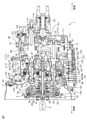
図1は、本発明の一実施形態に係る変速ユニット1の構成を示す断面図である。なお、図1以降の断面図では、断面を表すハッチングの付与が省略されている。
ユニットケース3は、第1ケース11、第2ケース12および第3ケース13の3分割で構成されている。第1ケース11、第2ケース12および第3ケース13は、たとえば、アルミ合金製であり、ダイカスト法によって鋳造される。
トルクコンバータ4は、第1ケース11内に収容されている。トルクコンバータ4は、フロントカバー21、ポンプインペラ22、タービンハブ23、タービンランナ24、ロックアップ機構25およびステータ26を備えている。
CVT5は、第2ケース12および第3ケース13内に収容されている。CVT5は、インプット軸41、無段変速機構42、アウトプット軸43およびリバース伝達機構44を備えている。変速ユニット1は、エンジン2の後側に、CVT5のインプット軸41が車両の前後方向に延びる縦向きとなる縦置きで、インプット軸41が後下がりに傾斜するように配置されている。
第2ケース12の底部には、変速ユニット1の各部へのオイルの供給を制御するためのバルブボディ121が設けられている。
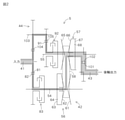
図2は、CVT5の構成を図解的に示すスケルトン図である。
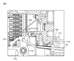
図3は、変速ユニット1の第2ケース12内を後側から見た図である。図4は、変速ユニット1の一部を前後方向に沿った断面で切断したときの断面図である。
以上のように、変速ユニット1は、エンジン2に対して軸線方向の一方側となる後側に配置されている。変速ユニット1には、プライマリプーリ56、セカンダリプーリ57およびベルト58が備えられている。プライマリプーリ56およびセカンダリプーリ57は、互いに軸線方向と直交する方向に間隔を空けて、それぞれ軸線方向に延びるプライマリ軸54およびセカンダリ軸55を中心に回転可能に設けられている。ベルト58は、プライマリプーリ56およびセカンダリプーリ57に巻き掛けられている。また、セカンダリプーリ57の後側には、セカンダリプーリ57から伝達される動力を出力するアウトプット軸43が設けられている。
以上、本発明の一実施形態について説明したが、本発明は、他の形態で実施することもできる。
2:エンジン
43:アウトプット軸
56:プライマリプーリ
57:セカンダリプーリ
58:ベルト
61:プライマリ固定シーブ
62:プライマリ可動シーブ
65:セカンダリ固定シーブ
66:セカンダリ可動シーブ
171:パーキング機構
172:パーキングギヤ
173:パーキングポール
184:係合部
Claims (2)
- エンジンに対して前記エンジンのクランク軸の軸線方向の一方側に配置され、前記エンジンが発生する動力を変速する変速機であって、
前記軸線方向に延びる回転軸線を中心に回転可能に設けられるプライマリプーリと、
前記軸線方向と直交する方向に間隔を空けて、前記軸線方向に延びる回転軸線を中心に回転可能に設けられるセカンダリプーリと、
前記プライマリプーリおよび前記セカンダリプーリに巻き掛けられる無端状のベルトと、
前記セカンダリプーリに対して前記軸線方向の前記一方側において、前記軸線方向に延びる回転軸線を中心に回転可能に設けられ、前記セカンダリプーリから伝達される動力を出力するアウトプット軸と、
前記セカンダリプーリに対して前記軸線方向の前記一方側と逆の前記エンジン側に設けられ、前記アウトプット軸の回転を規制するためのパーキング機構と、を含む、変速機。 - 前記プライマリプーリは、
前記軸線方向に固定されるプライマリ固定シーブと、
前記プライマリ固定シーブに前記ベルトを挟んで対向配置され、前記軸線方向に移動可能に設けられるプライマリ可動シーブと、を備え、
前記プライマリ可動シーブが前記プライマリ固定シーブに対して前記軸線方向の前記エンジン側に配置され、
前記セカンダリプーリは、
前記軸線方向に固定されるセカンダリ固定シーブと、
前記セカンダリ固定シーブに前記ベルトを挟んで対向配置され、前記軸線方向に移動可能に設けられるセカンダリ可動シーブと、を備え、
前記セカンダリ可動シーブが前記セカンダリ固定シーブに対して前記軸線方向の前記一方側に配置されており、
前記パーキング機構は、
前記セカンダリ固定シーブと一体に形成されるパーキングギヤと、
前記パーキングギヤの下方に配置されて、前記軸線方向に延びる軸を支点として揺動可能に設けられ、その揺動により前記パーキングギヤの歯溝に対して係合および離脱する係合部を有するパーキングポールと、を備える、請求項1に記載の変速機。
Priority Applications (1)
| Application Number | Priority Date | Filing Date | Title |
|---|---|---|---|
| JP2020113396A JP2022011960A (ja) | 2020-06-30 | 2020-06-30 | 変速機 |
Applications Claiming Priority (1)
| Application Number | Priority Date | Filing Date | Title |
|---|---|---|---|
| JP2020113396A JP2022011960A (ja) | 2020-06-30 | 2020-06-30 | 変速機 |
Publications (1)
| Publication Number | Publication Date |
|---|---|
| JP2022011960A true JP2022011960A (ja) | 2022-01-17 |
Family
ID=80147673
Family Applications (1)
| Application Number | Title | Priority Date | Filing Date |
|---|---|---|---|
| JP2020113396A Pending JP2022011960A (ja) | 2020-06-30 | 2020-06-30 | 変速機 |
Country Status (1)
| Country | Link |
|---|---|
| JP (1) | JP2022011960A (ja) |
Citations (2)
| Publication number | Priority date | Publication date | Assignee | Title |
|---|---|---|---|---|
| JPS5718844A (en) * | 1980-07-04 | 1982-01-30 | Nissan Motor Co Ltd | Stepless v-belt transmission |
| JP2000142133A (ja) * | 1998-11-05 | 2000-05-23 | Fuji Heavy Ind Ltd | 車両用駆動装置 |
-
2020
- 2020-06-30 JP JP2020113396A patent/JP2022011960A/ja active Pending
Patent Citations (2)
| Publication number | Priority date | Publication date | Assignee | Title |
|---|---|---|---|---|
| JPS5718844A (en) * | 1980-07-04 | 1982-01-30 | Nissan Motor Co Ltd | Stepless v-belt transmission |
| JP2000142133A (ja) * | 1998-11-05 | 2000-05-23 | Fuji Heavy Ind Ltd | 車両用駆動装置 |
Similar Documents
| Publication | Publication Date | Title |
|---|---|---|
| JP2022011960A (ja) | 変速機 | |
| JP7391464B2 (ja) | 変速機 | |
| JP7387222B2 (ja) | 変速機 | |
| JP7305526B2 (ja) | 変速機 | |
| JP7418926B2 (ja) | 変速機 | |
| JP7362217B2 (ja) | 変速機 | |
| JP7408384B2 (ja) | 動力伝達装置 | |
| JP7166736B2 (ja) | 変速機 | |
| JP7282565B2 (ja) | 変速機 | |
| JP7330613B2 (ja) | 変速機 | |
| JP7451031B2 (ja) | 変速機 | |
| JP7374557B2 (ja) | 変速機 | |
| JP7433721B2 (ja) | 変速機 | |
| JP7399569B2 (ja) | 無段変速機 | |
| JP7031999B2 (ja) | 変速機 | |
| JP7242133B2 (ja) | 変速機 | |
| JP7325898B2 (ja) | 変速機 | |
| JP7305375B2 (ja) | 変速機 | |
| JP7076918B2 (ja) | 変速機 | |
| JP7267829B2 (ja) | 変速機 | |
| JP7123505B2 (ja) | 変速機 | |
| JP7483307B2 (ja) | 変速ユニット | |
| JP2021124129A (ja) | 変速機 | |
| JP2021169857A (ja) | 油圧供給構造 | |
| JP2021105429A (ja) | オイル供給構造 |
Legal Events
| Date | Code | Title | Description |
|---|---|---|---|
| A621 | Written request for application examination |
Free format text: JAPANESE INTERMEDIATE CODE: A621 Effective date: 20220216 |
|
| A977 | Report on retrieval |
Free format text: JAPANESE INTERMEDIATE CODE: A971007 Effective date: 20221222 |
|
| A131 | Notification of reasons for refusal |
Free format text: JAPANESE INTERMEDIATE CODE: A131 Effective date: 20230131 |
|
| A521 | Request for written amendment filed |
Free format text: JAPANESE INTERMEDIATE CODE: A523 Effective date: 20230403 |
|
| A131 | Notification of reasons for refusal |
Free format text: JAPANESE INTERMEDIATE CODE: A131 Effective date: 20230726 |
|
| A521 | Request for written amendment filed |
Free format text: JAPANESE INTERMEDIATE CODE: A523 Effective date: 20230925 |
|
| A131 | Notification of reasons for refusal |
Free format text: JAPANESE INTERMEDIATE CODE: A131 Effective date: 20240109 |
|
| A521 | Request for written amendment filed |
Free format text: JAPANESE INTERMEDIATE CODE: A523 Effective date: 20240306 |