JP2019190815A - Recirculation heat pipe in which capillary member is put in part of cooling section - Google Patents
Recirculation heat pipe in which capillary member is put in part of cooling section Download PDFInfo
- Publication number
- JP2019190815A JP2019190815A JP2018120782A JP2018120782A JP2019190815A JP 2019190815 A JP2019190815 A JP 2019190815A JP 2018120782 A JP2018120782 A JP 2018120782A JP 2018120782 A JP2018120782 A JP 2018120782A JP 2019190815 A JP2019190815 A JP 2019190815A
- Authority
- JP
- Japan
- Prior art keywords
- capillary material
- cooling
- capillary
- housing
- connection end
- Prior art date
- Legal status (The legal status is an assumption and is not a legal conclusion. Google has not performed a legal analysis and makes no representation as to the accuracy of the status listed.)
- Pending
Links
Images


Classifications
-
- H—ELECTRICITY
- H01—ELECTRIC ELEMENTS
- H01L—SEMICONDUCTOR DEVICES NOT COVERED BY CLASS H10
- H01L23/00—Details of semiconductor or other solid state devices
- H01L23/34—Arrangements for cooling, heating, ventilating or temperature compensation ; Temperature sensing arrangements
- H01L23/42—Fillings or auxiliary members in containers or encapsulations selected or arranged to facilitate heating or cooling
- H01L23/427—Cooling by change of state, e.g. use of heat pipes
-
- B—PERFORMING OPERATIONS; TRANSPORTING
- B33—ADDITIVE MANUFACTURING TECHNOLOGY
- B33Y—ADDITIVE MANUFACTURING, i.e. MANUFACTURING OF THREE-DIMENSIONAL [3-D] OBJECTS BY ADDITIVE DEPOSITION, ADDITIVE AGGLOMERATION OR ADDITIVE LAYERING, e.g. BY 3-D PRINTING, STEREOLITHOGRAPHY OR SELECTIVE LASER SINTERING
- B33Y10/00—Processes of additive manufacturing
-
- F—MECHANICAL ENGINEERING; LIGHTING; HEATING; WEAPONS; BLASTING
- F28—HEAT EXCHANGE IN GENERAL
- F28D—HEAT-EXCHANGE APPARATUS, NOT PROVIDED FOR IN ANOTHER SUBCLASS, IN WHICH THE HEAT-EXCHANGE MEDIA DO NOT COME INTO DIRECT CONTACT
- F28D15/00—Heat-exchange apparatus with the intermediate heat-transfer medium in closed tubes passing into or through the conduit walls ; Heat-exchange apparatus employing intermediate heat-transfer medium or bodies
- F28D15/02—Heat-exchange apparatus with the intermediate heat-transfer medium in closed tubes passing into or through the conduit walls ; Heat-exchange apparatus employing intermediate heat-transfer medium or bodies in which the medium condenses and evaporates, e.g. heat pipes
- F28D15/0275—Arrangements for coupling heat-pipes together or with other structures, e.g. with base blocks; Heat pipe cores
-
- F—MECHANICAL ENGINEERING; LIGHTING; HEATING; WEAPONS; BLASTING
- F28—HEAT EXCHANGE IN GENERAL
- F28D—HEAT-EXCHANGE APPARATUS, NOT PROVIDED FOR IN ANOTHER SUBCLASS, IN WHICH THE HEAT-EXCHANGE MEDIA DO NOT COME INTO DIRECT CONTACT
- F28D15/00—Heat-exchange apparatus with the intermediate heat-transfer medium in closed tubes passing into or through the conduit walls ; Heat-exchange apparatus employing intermediate heat-transfer medium or bodies
- F28D15/02—Heat-exchange apparatus with the intermediate heat-transfer medium in closed tubes passing into or through the conduit walls ; Heat-exchange apparatus employing intermediate heat-transfer medium or bodies in which the medium condenses and evaporates, e.g. heat pipes
- F28D15/04—Heat-exchange apparatus with the intermediate heat-transfer medium in closed tubes passing into or through the conduit walls ; Heat-exchange apparatus employing intermediate heat-transfer medium or bodies in which the medium condenses and evaporates, e.g. heat pipes with tubes having a capillary structure
- F28D15/043—Heat-exchange apparatus with the intermediate heat-transfer medium in closed tubes passing into or through the conduit walls ; Heat-exchange apparatus employing intermediate heat-transfer medium or bodies in which the medium condenses and evaporates, e.g. heat pipes with tubes having a capillary structure forming loops, e.g. capillary pumped loops
-
- F—MECHANICAL ENGINEERING; LIGHTING; HEATING; WEAPONS; BLASTING
- F28—HEAT EXCHANGE IN GENERAL
- F28D—HEAT-EXCHANGE APPARATUS, NOT PROVIDED FOR IN ANOTHER SUBCLASS, IN WHICH THE HEAT-EXCHANGE MEDIA DO NOT COME INTO DIRECT CONTACT
- F28D15/00—Heat-exchange apparatus with the intermediate heat-transfer medium in closed tubes passing into or through the conduit walls ; Heat-exchange apparatus employing intermediate heat-transfer medium or bodies
- F28D15/02—Heat-exchange apparatus with the intermediate heat-transfer medium in closed tubes passing into or through the conduit walls ; Heat-exchange apparatus employing intermediate heat-transfer medium or bodies in which the medium condenses and evaporates, e.g. heat pipes
- F28D15/04—Heat-exchange apparatus with the intermediate heat-transfer medium in closed tubes passing into or through the conduit walls ; Heat-exchange apparatus employing intermediate heat-transfer medium or bodies in which the medium condenses and evaporates, e.g. heat pipes with tubes having a capillary structure
- F28D15/046—Heat-exchange apparatus with the intermediate heat-transfer medium in closed tubes passing into or through the conduit walls ; Heat-exchange apparatus employing intermediate heat-transfer medium or bodies in which the medium condenses and evaporates, e.g. heat pipes with tubes having a capillary structure characterised by the material or the construction of the capillary structure
-
- H—ELECTRICITY
- H05—ELECTRIC TECHNIQUES NOT OTHERWISE PROVIDED FOR
- H05K—PRINTED CIRCUITS; CASINGS OR CONSTRUCTIONAL DETAILS OF ELECTRIC APPARATUS; MANUFACTURE OF ASSEMBLAGES OF ELECTRICAL COMPONENTS
- H05K7/00—Constructional details common to different types of electric apparatus
- H05K7/20—Modifications to facilitate cooling, ventilating, or heating
- H05K7/2029—Modifications to facilitate cooling, ventilating, or heating using a liquid coolant with phase change in electronic enclosures
- H05K7/20336—Heat pipes, e.g. wicks or capillary pumps
Abstract
Description
本発明は、放熱装置に関し、詳しくは冷却部位の一部分に毛細管材が充填してある還流ヒートパイプに関するものである。 The present invention relates to a heat dissipation device, and more particularly to a reflux heat pipe in which a capillary material is filled in a part of a cooling portion.
科学技術が日増しに発展することに伴って、現代の日常生活では電子装置を使用することがごく普通になってきた。多くの電子装置は稼働を維持するために高い電気エネルギーが必要である。長時間にわたって電子装置が稼働して生じた熱は電子装置を昇温させると同時に電子装置を損傷し、電子装置の稼働効率に影響を与える。 With the ever-increasing development of science and technology, it has become very common to use electronic devices in modern daily life. Many electronic devices require high electrical energy to maintain operation. The heat generated by the operation of the electronic device for a long time increases the temperature of the electronic device and at the same time damages the electronic device, affecting the operating efficiency of the electronic device.
近年これに対して開発されたヒートパイプは熱伝導方式で熱伝導を迅速に促す冷却媒体を介して電子装置の熱エネルギーを外部に拡散させることが主な機能である。続いて開発されてきた還流ヒートパイプは内部に注入された作動流体、放熱装置、冷却装置、放熱装置および冷却装置の間に接続された気体管路および液体管路を備える。
電子装置に生じた熱エネルギーは放熱装置から作動流体に伝導する。作動流体は熱エネルギーを吸収し、蒸発して気体作動流体に変わる。続いて気体作動流体は気体管路を通って冷却装置に流入し、熱拡散、降温および冷却を行って液体作動流体に変わる。続いて液体作動流体は液体管路を通って放熱装置に還流し、再び放熱装置の表面に吸着した熱エネルギーを吸収し、蒸発(熱吸収)および冷却(熱放出)を繰り返すことによって電子装置を降温させる目的を達成する。
In recent years, a heat pipe developed for this has the main function of diffusing the heat energy of the electronic device to the outside through a cooling medium that rapidly promotes heat conduction by a heat conduction method. The reflux heat pipe that has been subsequently developed includes a working fluid injected into the inside, a heat radiating device, a cooling device, a heat radiating device, and a gas pipe and a liquid pipe connected between the cooling devices.
Thermal energy generated in the electronic device is conducted from the heat dissipation device to the working fluid. The working fluid absorbs thermal energy, evaporates and turns into a gaseous working fluid. Subsequently, the gas working fluid flows into the cooling device through the gas pipe, and is converted into a liquid working fluid by performing heat diffusion, temperature lowering and cooling. Subsequently, the liquid working fluid returns to the heat radiating device through the liquid pipe, absorbs the thermal energy adsorbed on the surface of the heat radiating device again, and repeats evaporation (heat absorption) and cooling (heat release) to Achieve the purpose of lowering the temperature.
特許文献1により掲示された「還流ヒートパイプ」は、液体管路の内部に配置された可撓性のあるメッシュ状脈管を有する。可撓性のあるメッシュ状脈管はメッシュ状管壁からなる毛細管構造によって毛細管力を生じ、作動流体を蒸発部位の方向へ伝送する。作動流体は蒸発部によって熱を吸収し、蒸発して気体作動流体に変わり、そののち蒸気管路によって冷却部へ流動する。続いて冷却部に流入した気体作動液は冷却して液体作動流体に変わり、冷却部の内壁に凝結する。
しかしながら、特許文献1において、可撓性のあるメッシュ状脈管は冷却部および液流流路に充満せず、冷却部(即ち管体内部)の側壁に配置されるため、冷却部の内壁に凝結した液体作動流体は直ちに脈管からなる毛細管構造に吸収されないことが原因で蒸発部に還流する速度が遅くなる。つまり液体作動流体は還流効果がよくない。
The “reflux heat pipe” posted by Patent Document 1 has a flexible mesh-like vessel disposed inside a liquid conduit. The flexible mesh-like vasculature generates capillary force by the capillary structure composed of the mesh-like tube wall, and transmits the working fluid toward the evaporation site. The working fluid absorbs heat by the evaporating unit, evaporates to be converted into a gas working fluid, and then flows to the cooling unit through the vapor line. Subsequently, the gas hydraulic fluid that has flowed into the cooling section is cooled to change into a liquid working fluid, and condenses on the inner wall of the cooling section.
However, in Patent Document 1, the flexible mesh-shaped vascular vessel does not fill the cooling part and the liquid flow channel, and is disposed on the side wall of the cooling part (that is, inside the tubular body). Since the condensed liquid working fluid is not immediately absorbed by the capillary structure composed of the vasculature, the speed at which the condensed liquid working fluid is returned to the evaporation section is reduced. That is, the liquid working fluid does not have a good reflux effect.
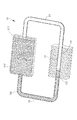
上述した問題に対し、図1に示すように、液流部位および冷却部に液体作動流体を充満させるには大量の作動流体を注入することが必要であり、その一方で冷却部内の気体作動流体を入流させる空間を大幅に縮減する。つまり気体作動流体は転換空間および転換できる量が限定されるため、放熱効率を降下させてしまう。 To solve the above-described problem, as shown in FIG. 1, it is necessary to inject a large amount of working fluid in order to fill the liquid flow site and the cooling portion with the liquid working fluid, while the gas working fluid in the cooling portion. Drastically reduce the space to enter. That is, since the gas working fluid is limited in the conversion space and the amount that can be converted, the heat dissipation efficiency is lowered.
本発明は、冷却部位の一部分に毛細管材が充填してある還流ヒートパイプを提供することを主な目的とする。
本発明の冷却部位の一部分に毛細管材が充填してある還流ヒートパイプは、先行技術のように大量の作動液を注入する必要なく、液体作動液を確実に吸収し、液体作動液を迅速に還流させ、放熱効率を高めることができる。
The main object of the present invention is to provide a reflux heat pipe in which a capillary material is filled in a part of a cooling portion.
The reflux heat pipe in which the capillary material is filled in a part of the cooling part of the present invention reliably absorbs the liquid hydraulic fluid and quickly absorbs the liquid hydraulic fluid without the need to inject a large amount of hydraulic fluid as in the prior art. Refluxing can improve the heat dissipation efficiency.
上述した課題を解決するため、冷却部位の一部分に毛細管材が充填してある還流ヒートパイプは、蒸発チャンバー、冷却部位、気流管および液流管を備える。蒸発チャンバーはハウジングと、ハウジング内に配置された第一毛細管材とを有する。第一毛細管材はハウジングに充満せず、ハウジングとの間に第一空間を形成する。冷却部位は内部が中空の管体からなる。放熱部材は管体の外部に配置される。管体は相互に繋がる気体接続端部および液体接続端部、内部の一部分に充填された第二毛細管材と、内部に形成された第二空間とを有する。第二毛細管材は管体の液体接続端部に対応するように配置される。第二空間は一端が第二毛細管材に接触し、他端が気体接続端部に繋がる。気流管は一端がハウジングに接続されて第一空間に繋がり、他端が冷却部位の気体接続端部に接続されて第二空間に繋がる。液流管は一端がハウジングに接続されてハウジングの内部に繋がり、他端が冷却部位の液体接続端部に接続されて冷却部位の内部に繋がる。液流管は第三毛細管材を有する。第三毛細管材は液流管の内部に充填され、第一毛細管材および第二毛細管材に別々に接触する。 In order to solve the above-described problem, a reflux heat pipe in which a capillary material is filled in a part of a cooling portion includes an evaporation chamber, a cooling portion, an air flow tube, and a liquid flow tube. The evaporation chamber has a housing and a first capillary material disposed in the housing. The first capillary material does not fill the housing and forms a first space with the housing. The cooling part is composed of a hollow tube. The heat radiating member is disposed outside the tube body. The tube has a gas connection end and a liquid connection end connected to each other, a second capillary filled in a part of the inside, and a second space formed inside. The second capillary material is disposed so as to correspond to the liquid connection end portion of the tubular body. One end of the second space is in contact with the second capillary material, and the other end is connected to the gas connection end. One end of the airflow tube is connected to the housing and connected to the first space, and the other end is connected to the gas connection end of the cooling part and connected to the second space. One end of the liquid flow pipe is connected to the housing and connected to the inside of the housing, and the other end is connected to the liquid connection end of the cooling part and connected to the inside of the cooling part. The liquid flow tube has a third capillary material. The third capillary material is filled inside the liquid flow tube and contacts the first capillary material and the second capillary material separately.
上述したとおり、冷却部位は内部に形成された第二空間および内部の一部分に充填された第二毛細管材によって気体作動液を集結し、第二毛細管材の吸収作用によって冷却した液体作動液を蒸発チャンバーに迅速に還流させ、再び循環させるため、放熱を加速させることができる。 As described above, the cooling portion collects the gas hydraulic fluid by the second capillary formed in the second space formed inside and a part of the interior, and evaporates the liquid hydraulic fluid cooled by the absorption action of the second capillary. Heat release can be accelerated because the chamber is quickly refluxed and circulated again.
以下、本発明による冷却部位の一部分に毛細管材が充填してある還流ヒートパイプを図面に基づいて説明する。 Hereinafter, a reflux heat pipe in which a capillary material is filled in a part of a cooling portion according to the present invention will be described with reference to the drawings.
(第1実施形態)
図1から図3に示すように、本発明の第1実施形態による冷却部位の一部分に毛細管材が充填してある還流ヒートパイプ10は、蒸発チャンバー11、冷却部位12、気流管13および液流管14から構成される。
(First embodiment)
As shown in FIGS. 1 to 3, a
蒸発チャンバー11は、ハウジング111と、ハウジング111内に配置された第一毛細管材112とを有する。図面に示すように、ハウジング111は矩形を呈するのに対し、第一毛細管材112は矩形を呈し、長さがハウジング111の長さより小さい。
第一毛細管材112はハウジング111に充満せず、ハウジング111との間に第一空間113を形成する。作動液(図中未表示)はハウジング111内に注入され、第一毛細管材112を流動する。第一毛細管材112は焼結粉末、(sintered powder)、メッシュ(mesh)または ファイバー(fiber)からなる毛細管構造であり、複数の流路1121を有する。流路1121は周知であるため、詳しい説明を省略する。複数の流路1121の開口部1122は第一空間113に対応する。
The
The first
冷却部位12は、内部が中空の管体からなり、相互に繋がる気体接続端部121および液体接続端部122、管体内部の一部分に充填された第二毛細管材123と、管体内部に形成された第二空間124とを有する。放熱部材15は管体の外部に配置される、例えば放熱フィンから構成され、冷却部位12の外側の周辺に配置され、放熱および降温作用を生じる。放熱部材は形および構造が特に限定されず、周知の技術であるため、詳細な説明を省略する。
第二毛細管材123は焼結粉末、(sintered powder)、メッシュ(mesh)または ファイバー(fiber)からなる毛細管構造である。本実施形態において、第二毛細管材123は円柱形を呈し、管体の液体接続端部122に対応するように冷却部位12内に配置される。第二空間124は一端が第二毛細管材123に接触し、他端が気体接続端部121に繋がる。
The
The second
気流管13は一端がハウジング111に接続されて第一空間113に繋がり、他端が冷却部位12の気体接続端部121に接続されて第二空間124に繋がる。
One end of the
第1実施形態において、液流管14は内径が気流管13の内径より大きく、一端がハウジング111に接続されてハウジング111の内部に繋がり、他端が冷却部位12の液体接続端部122に接続されて冷却部位12の内部に繋がる。
液流管14は第三毛細管材141を有する。第三毛細管材141は液流管14の内部に充填され、焼結粉末、(sintered powder)、メッシュ(mesh)または ファイバー(fiber)からなる毛細管構造であり、第一毛細管材112および第二毛細管材123に別々に接触する。
In the first embodiment, the
The
図2に示すように、第一毛細管材112、第二毛細管材123および第三毛細管材141は独立毛細管構造であってもよい。第一毛細管材112はハウジング111内に配置され、第二毛細管材123は冷却部位12内に配置され、第三毛細管材141は液流管14内に配置される。或いは、図3に示すように、第一毛細管材112、第二毛細管材123および第三毛細管材141は焼結成形によって一体になり、ハウジング111、冷却部位12および液流管14内に配置される。
As shown in FIG. 2, the first
上述した構造により、還流ヒートパイプ10が作動する際、電子装置などの発熱源(図中未表示)は蒸発チャンバー11の上に配置され、暫く稼働した後、熱エネルギーを生じ、熱伝導方式によって蒸発チャンバー11に伝導させ、同時に第一毛細管材112へ拡散させる。作動液の大部分は液体状態で第一毛細管材112内に保存される。
熱エネルギーが第一毛細管材112に伝導する際、第一毛細管材112は昇温し、第一毛細管材112内の液体作動液に熱エネルギーを十分に吸収させ、蒸発反応を起こして気体作動液を生成させる。気体作動液は第一毛細管材112の複数の流路1121の開口部1122から第一空間113に流入し、集結した後、気流管13を通って冷却部位12へ流動する。
冷却部位12の外部に配置される放熱部材15は気流管13から冷却部位12に流入した気体作動液を冷却させて液体作動液を生成する。一方、気体作動液が気流管13から冷却部位12へ流入する際、冷却部位12は第二空間124および冷却部位12の一部分に充填された第二毛細管材123を有するため、気体作動液は第二空間124に集結および冷却し、液体作動液を凝結させることができる。
Due to the above-described structure, when the
When the thermal energy is conducted to the first
The
続いて、冷却部位12内の第二毛細管材123が液流管14内の第三毛細管材141に接触するため、液体作動液は毛細管力の吸着作用によって液流管14へ持続的に流動し、蒸発チャンバー11に還流することができる。上述したステップを繰り返せば、還流ヒートパイプの放熱効率を向上させる目的を達成することができる。
Subsequently, since the
上述したとおり、本発明は冷却部位12の一部分に第二毛細管材123が充填してあるため、液体作動液は第二毛細管材123に吸着し、第三毛細管材141によって蒸発チャンバー11に迅速に還流することができる。従って、本発明の放熱効率は先行技術に優れる。
As described above, according to the present invention, the
(第2実施形態)
図4から図6に示したのは本発明の第2実施形態による冷却部位の一部分に毛細管材が充填してある還流ヒートパイプ10’である。第1実施形態との違いは下記のとおりである。
(Second Embodiment)
4 to 6 show a reflux heat pipe 10 'in which a capillary material is filled in a part of a cooling portion according to the second embodiment of the present invention. Differences from the first embodiment are as follows.
第2実施形態において、第二毛細管材123’は円筒体である。円筒体は底部1231’が冷却部位12’の液体接続端部122’に隣接し、身部1232’が円柱状を呈し、底部1231’の外周から冷却部位12’の内壁に沿って冷却部位12’の気体接続端部121’へ伸びていく。
第二毛細管材123’は冷却部位12’内に配置されて第二空間124’を形成する。第二空間124’は長円柱状を呈し、密封端部1241’および開口端部1242’を有する。密封端部1241’は第二毛細管材123’に隣接する。開口端部1242’は気体接続端部121’に対応する。気体作動液は冷却部位12’の内周壁面に配置された第二毛細管材123’によって熱エネルギーを冷却部位12’の外部へ迅速かつ均等に拡散させ、放熱部材15’とともに放熱および降温作用を発揮する。
冷却した液体作動液は第二毛細管材123’の毛細管作用によって液流管14’へ迅速および順調に流動することができる。
In 2nd Embodiment, 2nd capillary material 123 'is a cylindrical body. The cylindrical body has a bottom portion 1231 'adjacent to the liquid connection end portion 122' of the cooling portion 12 ', a body portion 1232' has a columnar shape, and the cooling
The second
The cooled liquid working fluid can quickly and smoothly flow to the
図4および図5に示すように、第一毛細管材112’、第二毛細管材123’および第三毛細管材141’は独立毛細管構造であってもよい。第一毛細管材112’はハウジング111’内に配置され、第二毛細管材123’は冷却部位12’内に配置され、第三毛細管材141’は液流管14’内に配置される。
或いは、図6に示すように、第一毛細管材112’、第二毛細管材123’および第三毛細管材141’は焼結成形によって一体になり、ハウジング111’、冷却部位12’および液流管14’内に配置される。
As shown in FIGS. 4 and 5, the
Alternatively, as shown in FIG. 6, the first
第2実施形態のほかの構造および達成できる効果は第1実施形態と同じであるため、詳細な説明を省略する。 Since the other structures and effects that can be achieved in the second embodiment are the same as those in the first embodiment, a detailed description thereof will be omitted.
(第3実施形態)
図7に示したのは本発明の第3実施形態による冷却部位の一部分に毛細管材が充填してある還流ヒートパイプ20である。第1実施形態との違いは下記のとおりである。
(Third embodiment)
FIG. 7 shows a
第3実施形態において、気流管23および液流管24は内径が同じであり、それぞれ冷却部位22に連結される。液流管24は第三毛細管材241を有する。第三毛細管材241は液流管24の内部に充填され、ハウジング211内の第一毛細管材212および冷却部位22の第二毛細管材223に接触する。第二毛細管材223は円柱形を呈する。
In the third embodiment, the
第3実施形態において、第一毛細管材212、第二毛細管材223および第三毛細管材241は独立毛細管構造であってもよい。第一毛細管材212はハウジング211内に配置され、第二毛細管材223は冷却部位22内に配置され、第三毛細管材241は液流管24内に配置される。
或いは、図7に示すように第一毛細管材212、第二毛細管材223および第三毛細管材241は焼結成形によって一体になり、ハウジング211、冷却部位22および液流管24内に配置される。
In the third embodiment, the first
Alternatively, as shown in FIG. 7, the first
第3実施形態のほかの構造および達成できる効果は第1実施形態と同じであるため、詳細な説明を省略する。 Since the other structures and effects that can be achieved in the third embodiment are the same as those in the first embodiment, detailed description thereof is omitted.
(第4実施形態)
図8に示したのは本発明の第4実施形態による冷却部位の一部分に毛細管材が充填してある還流ヒートパイプ20’である。第1実施形態との違いは下記のとおりである。
(Fourth embodiment)
FIG. 8 shows a
第4実施形態において、気流管23’および液流管24’は内径が同じであり、それぞれ冷却部位22’に連結される。液流管24’は第三毛細管材241’を有する。第三毛細管材241’は液流管24’の内部に充填され、ハウジング211’内の第一毛細管材212’および冷却部位22’内の第二毛細管材223’に接触する。
図8に示すように、第二毛細管材223’は円筒体である。円筒体は底部2231’が冷却部位22’の液体接続端部222’に隣接し、身部2232’が円柱状を呈し、底部2231’の外周から冷却部位22’の内壁に沿って冷却部位22’の気体接続端部221’へ伸びていく。
In the fourth embodiment, the
As shown in FIG. 8, the second
第4実施形態において、第一毛細管材212’、第二毛細管材223’および第三毛細管材241’は独立毛細管構造であってもよい。第一毛細管材212’はハウジング211’内に配置され、第二毛細管材223’は冷却部位22’内に配置され、第三毛細管材241’は液流管24’内に配置される。
或いは、図8に示すように、第一毛細管材212’、第二毛細管材223’および第三毛細管材241’は焼結成形によって一体になり、ハウジング211’、冷却部位22’および液流管24’内に配置される。
In the fourth embodiment, the first
Alternatively, as shown in FIG. 8, the first
第4実施形態のほかの構造および達成できる効果は第1実施形態と同じであるため、詳細な説明を省略する。 Since the other structures and effects that can be achieved in the fourth embodiment are the same as those in the first embodiment, a detailed description thereof will be omitted.
(第5実施形態)
図9に示したのは本発明の第5実施形態による冷却部位の一部分に毛細管材が充填してある還流ヒートパイプ20”である。第2実施形態との違いは下記のとおりである。
(Fifth embodiment)
FIG. 9 shows a
第5実施形態において、液流管24”は内径が気流管23”の内径より小さい。気流管23”および液流管24”はそれぞれ冷却部位22”に連結される。液流管24”は第三毛細管材241”を有する。第三毛細管材241”は液流管24”の内部に充填され、ハウジング211”内の第一毛細管材212”および冷却部位22”内の第二毛細管材223”に接触する。
In the fifth embodiment, the
第5実施形態のほかの構造および達成できる効果は第2実施形態と同じであるため、詳細な説明を省略する。 Since the other structures of the fifth embodiment and the effects that can be achieved are the same as those of the second embodiment, detailed description thereof is omitted.
上述したとおり、本発明は冷却部位12、12’、22、22’、22”内に第二毛細管材123、123’、223、223’、223”および第二空間124、124’、224、224’、224”を配置し、液流管14、14’、24、24’、24”内に第三毛細管材141、141’、241、241’、241”を配置する空間形態によって還流ヒートパイプの放熱効率を向上させる目的を達成できることが判明した。
As described above, the present invention includes the second
10、10’、20、20’、20” 還流ヒートパイプ
11、11’ 蒸発チャンバー
111、111’、211、211’、211” ハウジング
112、112’、212、212’、212” 第一毛細管材
1121、1121’ 流路
1122、1122’ 開口部
113、113’ 第一空間
12、12’、22、22’、22” 冷却部位
121、121’ 気体接続端部
122、122’ 液体接続端部
123、123’、223、223’、223” 第二毛細管材
1231’、2231’ 底部
1232’、2232’ 身部
124、124’、224、224’、224” 第二空間
1241’ 密封端部
1242’ 開口端部
13、13’、23、23’、23” 気流管
14、14’、24、24’、24” 液流管
141、141’、241、241’、241” 第三毛細管材
15、15’ 放熱部材
10, 10 ', 20, 20', 20 "
Claims (7)
前記蒸発チャンバーは、ハウジングと、前記ハウジング内に配置された第一毛細管材とを有し、前記第一毛細管材は前記ハウジングの内部に充満せず、前記ハウジングとの間に第一空間を形成し、
前記冷却部位は、内部が中空の管体からなり、放熱部材は前記管体の外部に配置され、前記管体は相互に繋がる気体接続端部および液体接続端部と、内部の一部分に充填された第二毛細管材と、内部に形成された第二空間とを有し、前記第二毛細管材は前記管体の前記液体接続端部に対応するように配置され、前記第二空間は一端が前記第二毛細管材に接触し、他端が前記気体接続端部に繋がり、
前記気流管は、一端が前記ハウジングに接続されて前記第一空間に繋がり、他端が前記冷却部位の前記気体接続端部に接続されて前記第二空間に繋がり、
前記液流管は、内部に第三毛細管材を有し、一端が前記ハウジングに接続されて前記ハウジングの内部に繋がり、他端が前記冷却部位の前記液体接続端部に接続されて前記冷却部位の内部に繋がり、前記第三毛細管材は前記液流管の内部に充填され、前記第一毛細管材および前記第二毛細管材に別々に接触することを特徴とする、
冷却部位の一部分に毛細管材が充填してある還流ヒートパイプ。 Evaporation chamber, cooling site, airflow tube and liquid flow tube
The evaporation chamber has a housing and a first capillary material disposed in the housing, and the first capillary material does not fill the interior of the housing and forms a first space between the housing and the housing. And
The cooling part is composed of a hollow tubular body, the heat dissipating member is disposed outside the tubular body, and the tubular body is filled with a gas connection end and a liquid connection end connected to each other and a part of the interior. A second space formed therein, the second capillary material is disposed so as to correspond to the liquid connection end of the tube, and the second space has one end. Contacting the second capillary material, the other end is connected to the gas connection end,
One end of the airflow tube is connected to the housing and connected to the first space, and the other end is connected to the gas connection end of the cooling part and connected to the second space.
The liquid flow pipe has a third capillary material inside, one end connected to the housing and connected to the inside of the housing, and the other end connected to the liquid connection end of the cooling part and the cooling part. The third capillary material is filled in the liquid flow tube, and is in contact with the first capillary material and the second capillary material separately,
A reflux heat pipe in which a capillary material is filled in a part of the cooling part.
Applications Claiming Priority (2)
| Application Number | Priority Date | Filing Date | Title |
|---|---|---|---|
| TW107114331A TWI660151B (en) | 2018-04-26 | 2018-04-26 | Loop heat pipe partially filled with capillary material in the condensation section |
| TW107114331 | 2018-04-26 |
Publications (1)
| Publication Number | Publication Date |
|---|---|
| JP2019190815A true JP2019190815A (en) | 2019-10-31 |
Family
ID=67348963
Family Applications (1)
| Application Number | Title | Priority Date | Filing Date |
|---|---|---|---|
| JP2018120782A Pending JP2019190815A (en) | 2018-04-26 | 2018-06-26 | Recirculation heat pipe in which capillary member is put in part of cooling section |
Country Status (3)
| Country | Link |
|---|---|
| US (1) | US20190331432A1 (en) |
| JP (1) | JP2019190815A (en) |
| TW (1) | TWI660151B (en) |
Families Citing this family (9)
| Publication number | Priority date | Publication date | Assignee | Title |
|---|---|---|---|---|
| JP6860086B2 (en) * | 2017-11-29 | 2021-04-14 | 富士通株式会社 | Loop heat pipes and electronics |
| JP7028659B2 (en) * | 2018-01-30 | 2022-03-02 | 新光電気工業株式会社 | Manufacturing method of loop type heat pipe and loop type heat pipe |
| JP6697112B1 (en) | 2019-05-10 | 2020-05-20 | 古河電気工業株式会社 | heatsink |
| CN110806130B (en) * | 2019-11-14 | 2022-04-01 | 中山大学 | Loop heat pipe of electrodeposition evaporator and preparation method thereof |
| CN112566465B (en) * | 2020-12-08 | 2022-02-08 | 泰睿(北京)技术服务有限公司 | Built-in heat abstractor of quick-witted case based on loop heat pipe |
| TWI809346B (en) * | 2021-01-07 | 2023-07-21 | 大陸商深圳興奇宏科技有限公司 | Flexible heat dissipation device |
| US11815315B2 (en) | 2021-02-18 | 2023-11-14 | Asia Vital Components (China) Co., Ltd. | Flexible heat dissipation device |
| US20240044582A1 (en) * | 2021-03-01 | 2024-02-08 | ShengRongYuan(Suzhou) Technology Co., Ltd | Thin-plate loop heat pipe |
| US20220407148A1 (en) * | 2021-06-17 | 2022-12-22 | GM Global Technology Operations LLC | Battery system including a self-regulating cooling system |
Family Cites Families (6)
| Publication number | Priority date | Publication date | Assignee | Title |
|---|---|---|---|---|
| TWI286193B (en) * | 2006-04-21 | 2007-09-01 | Foxconn Tech Co Ltd | Heat pipe |
| TWI302190B (en) * | 2006-04-28 | 2008-10-21 | Foxconn Tech Co Ltd | Heat pipe |
| TW201104202A (en) * | 2009-07-24 | 2011-02-01 | Foxconn Tech Co Ltd | Loop heat pipe |
| TW201209366A (en) * | 2010-08-24 | 2012-03-01 | Foxconn Tech Co Ltd | Loop heat pipe |
| TWI577958B (en) * | 2012-03-09 | 2017-04-11 | 鴻準精密工業股份有限公司 | Plate-type heat pipe |
| TWM550818U (en) * | 2017-06-23 | 2017-10-21 | 雙鴻科技股份有限公司 | Loop heat pipe and electronic device having the same |
-
2018
- 2018-04-26 TW TW107114331A patent/TWI660151B/en active
- 2018-06-26 JP JP2018120782A patent/JP2019190815A/en active Pending
- 2018-07-13 US US16/034,838 patent/US20190331432A1/en not_active Abandoned
Also Published As
| Publication number | Publication date |
|---|---|
| TW201945683A (en) | 2019-12-01 |
| TWI660151B (en) | 2019-05-21 |
| US20190331432A1 (en) | 2019-10-31 |
Similar Documents
| Publication | Publication Date | Title |
|---|---|---|
| JP2019190815A (en) | Recirculation heat pipe in which capillary member is put in part of cooling section | |
| JP5789684B2 (en) | Vapor chamber | |
| JP4881352B2 (en) | HEAT SPREADER, ELECTRONIC DEVICE, AND HEAT SPREADER MANUFACTURING METHOD | |
| KR100495699B1 (en) | Flat plate heat transferring apparatus and manufacturing method thereof | |
| JP5637216B2 (en) | Loop heat pipe and electronic equipment | |
| US9453688B2 (en) | Heat dissipation unit | |
| US20120227935A1 (en) | Interconnected heat pipe assembly and method for manufacturing the same | |
| WO2006119684A1 (en) | A integrative heat pipe heat exchanging structure | |
| CN211429852U (en) | Heat dissipation plate and electronic device with same | |
| JP2019015443A (en) | heat pipe | |
| JP2019184219A (en) | Reflow heat pipe with liquid bullet pipe conduit | |
| JP5370074B2 (en) | Loop type heat pipe and electronic device equipped with the same | |
| JP3156954U (en) | Support structure for flat plate heat pipe | |
| CN112996339A (en) | Temperature equalizing plate device | |
| US20200378690A1 (en) | Heat dissipation unit with axial capillary structure | |
| JP3168202U (en) | Structure of thin plate heat pipe | |
| US20120037344A1 (en) | Flat heat pipe having swirl core | |
| TWI530655B (en) | Plate type heat pipe | |
| JP2007003034A (en) | Cooling device | |
| JP2019190812A (en) | Recirculation heat pipe in which same pipe line is partitioned into air current passage and fluid current passage | |
| JP3209501U (en) | Heat dissipation unit | |
| JP2019190811A (en) | Recirculation heat pipe with different bore diameters | |
| TWI507653B (en) | Heat dissipation unit | |
| WO2017082127A1 (en) | Electronic equipment cooling device | |
| CN216282942U (en) | Temperature equalizing plate |
Legal Events
| Date | Code | Title | Description |
|---|---|---|---|
| A621 | Written request for application examination |
Free format text: JAPANESE INTERMEDIATE CODE: A621 Effective date: 20180627 |
|
| A131 | Notification of reasons for refusal |
Free format text: JAPANESE INTERMEDIATE CODE: A131 Effective date: 20190611 |
|
| A02 | Decision of refusal |
Free format text: JAPANESE INTERMEDIATE CODE: A02 Effective date: 20200204 |