JP2019190812A - Recirculation heat pipe in which same pipe line is partitioned into air current passage and fluid current passage - Google Patents
Recirculation heat pipe in which same pipe line is partitioned into air current passage and fluid current passage Download PDFInfo
- Publication number
- JP2019190812A JP2019190812A JP2018117824A JP2018117824A JP2019190812A JP 2019190812 A JP2019190812 A JP 2019190812A JP 2018117824 A JP2018117824 A JP 2018117824A JP 2018117824 A JP2018117824 A JP 2018117824A JP 2019190812 A JP2019190812 A JP 2019190812A
- Authority
- JP
- Japan
- Prior art keywords
- pipe
- reflux
- flow channel
- reflux pipe
- housing
- Prior art date
- Legal status (The legal status is an assumption and is not a legal conclusion. Google has not performed a legal analysis and makes no representation as to the accuracy of the status listed.)
- Pending
Links
- 239000012530 fluid Substances 0.000 title claims abstract description 23
- 238000001704 evaporation Methods 0.000 claims abstract description 31
- 230000008020 evaporation Effects 0.000 claims abstract description 31
- 125000006850 spacer group Chemical group 0.000 claims abstract description 25
- 239000000463 material Substances 0.000 claims abstract description 23
- 238000010992 reflux Methods 0.000 claims description 94
- 239000007788 liquid Substances 0.000 claims description 73
- 238000005192 partition Methods 0.000 claims description 5
- 230000008878 coupling Effects 0.000 claims description 4
- 238000010168 coupling process Methods 0.000 claims description 4
- 238000005859 coupling reaction Methods 0.000 claims description 4
- 230000005855 radiation Effects 0.000 abstract description 4
- 238000007789 sealing Methods 0.000 description 7
- 230000017525 heat dissipation Effects 0.000 description 5
- 230000013011 mating Effects 0.000 description 5
- 238000001816 cooling Methods 0.000 description 4
- 230000000694 effects Effects 0.000 description 4
- XLYOFNOQVPJJNP-UHFFFAOYSA-N water Substances O XLYOFNOQVPJJNP-UHFFFAOYSA-N 0.000 description 3
- 239000000945 filler Substances 0.000 description 2
- 238000004519 manufacturing process Methods 0.000 description 2
- 238000000638 solvent extraction Methods 0.000 description 2
- RYGMFSIKBFXOCR-UHFFFAOYSA-N Copper Chemical compound [Cu] RYGMFSIKBFXOCR-UHFFFAOYSA-N 0.000 description 1
- 238000006243 chemical reaction Methods 0.000 description 1
- 238000000034 method Methods 0.000 description 1
- 238000005245 sintering Methods 0.000 description 1
Images

Classifications
-
- F—MECHANICAL ENGINEERING; LIGHTING; HEATING; WEAPONS; BLASTING
- F28—HEAT EXCHANGE IN GENERAL
- F28D—HEAT-EXCHANGE APPARATUS, NOT PROVIDED FOR IN ANOTHER SUBCLASS, IN WHICH THE HEAT-EXCHANGE MEDIA DO NOT COME INTO DIRECT CONTACT
- F28D15/00—Heat-exchange apparatus with the intermediate heat-transfer medium in closed tubes passing into or through the conduit walls ; Heat-exchange apparatus employing intermediate heat-transfer medium or bodies
- F28D15/02—Heat-exchange apparatus with the intermediate heat-transfer medium in closed tubes passing into or through the conduit walls ; Heat-exchange apparatus employing intermediate heat-transfer medium or bodies in which the medium condenses and evaporates, e.g. heat pipes
- F28D15/0266—Heat-exchange apparatus with the intermediate heat-transfer medium in closed tubes passing into or through the conduit walls ; Heat-exchange apparatus employing intermediate heat-transfer medium or bodies in which the medium condenses and evaporates, e.g. heat pipes with separate evaporating and condensing chambers connected by at least one conduit; Loop-type heat pipes; with multiple or common evaporating or condensing chambers
-
- F—MECHANICAL ENGINEERING; LIGHTING; HEATING; WEAPONS; BLASTING
- F28—HEAT EXCHANGE IN GENERAL
- F28D—HEAT-EXCHANGE APPARATUS, NOT PROVIDED FOR IN ANOTHER SUBCLASS, IN WHICH THE HEAT-EXCHANGE MEDIA DO NOT COME INTO DIRECT CONTACT
- F28D15/00—Heat-exchange apparatus with the intermediate heat-transfer medium in closed tubes passing into or through the conduit walls ; Heat-exchange apparatus employing intermediate heat-transfer medium or bodies
- F28D15/02—Heat-exchange apparatus with the intermediate heat-transfer medium in closed tubes passing into or through the conduit walls ; Heat-exchange apparatus employing intermediate heat-transfer medium or bodies in which the medium condenses and evaporates, e.g. heat pipes
- F28D15/0283—Means for filling or sealing heat pipes
-
- F—MECHANICAL ENGINEERING; LIGHTING; HEATING; WEAPONS; BLASTING
- F28—HEAT EXCHANGE IN GENERAL
- F28D—HEAT-EXCHANGE APPARATUS, NOT PROVIDED FOR IN ANOTHER SUBCLASS, IN WHICH THE HEAT-EXCHANGE MEDIA DO NOT COME INTO DIRECT CONTACT
- F28D15/00—Heat-exchange apparatus with the intermediate heat-transfer medium in closed tubes passing into or through the conduit walls ; Heat-exchange apparatus employing intermediate heat-transfer medium or bodies
- F28D15/02—Heat-exchange apparatus with the intermediate heat-transfer medium in closed tubes passing into or through the conduit walls ; Heat-exchange apparatus employing intermediate heat-transfer medium or bodies in which the medium condenses and evaporates, e.g. heat pipes
- F28D15/04—Heat-exchange apparatus with the intermediate heat-transfer medium in closed tubes passing into or through the conduit walls ; Heat-exchange apparatus employing intermediate heat-transfer medium or bodies in which the medium condenses and evaporates, e.g. heat pipes with tubes having a capillary structure
Abstract
Description
本発明は、放熱装置に関し、詳しくは同じ管路が気流流路および液流流路に仕切られた還流ヒートパイプに関するものである。 The present invention relates to a heat radiating device, and more particularly to a reflux heat pipe in which the same pipe is divided into an air flow channel and a liquid flow channel.
特許文献1により掲示された還流ヒートパイプにおいて、中空パイプは折り曲げられ、二つの管路に分割され、一つの管路が蒸発部位となり、別の一つの管路が冷却部位となる。二つの管路の開口部は密封キャップに嵌合され、相対する側の管壁が平坦な壁面に形成され、相互に密着する。密封キャップは密封端部および嵌合端部を有する。嵌合端部はスリーブの形である。二つの管路を組み合わせる際、密封キャップはスリーブの形で二つの管路を連結することができる。
特許文献2により掲示された還流ヒートパイプにおいて、中空パイプは二つの管路を有し、一つの管路が蒸発部位となり、別の一つの管路が冷却部位となる。密封キャップは密封端部および嵌合端部を有する。嵌合端部はスリーブの形である。二つの管路を組み合わせる際、スリーブの形の嵌合端部と二つの管路の開口部との間の隙間を充填剤で埋める。
特許文献1および特許文献2において、蒸発部位となる管路および冷却部位となる管路は同じ大直径の管体であるが、冷却した液体を容易に流動させるように設計されなかったため、液体状態で流動する作動液は蒸発チャンバーに還流することが順調でなく、循環速度が遅く、放熱効率に影響を与える。一方、密封キャップと管体は組み合わせにくいため、管体の形を変えるか、再び隙間に填充剤を充填することが必要であれば、製造コストが増加する。
In the reflux heat pipe posted by patent document 1, a hollow pipe is bent and divided | segmented into two pipe lines, one pipe line becomes an evaporation part, and another one pipe line becomes a cooling part. The openings of the two pipe lines are fitted into a sealing cap, and the opposite pipe wall is formed on a flat wall surface so as to be in close contact with each other. The sealing cap has a sealing end and a mating end. The mating end is in the form of a sleeve. When combining two lines, the sealing cap can connect the two lines in the form of a sleeve.
In the reflux heat pipe posted by patent document 2, a hollow pipe has two pipe lines, one pipe line becomes an evaporation site | part, and another one pipe line becomes a cooling site | part. The sealing cap has a sealing end and a mating end. The mating end is in the form of a sleeve. When combining the two lines, the gap between the mating end in the form of a sleeve and the opening of the two lines is filled with a filler.
In Patent Document 1 and Patent Document 2, the pipeline serving as the evaporation site and the pipeline serving as the cooling site are the same large-diameter tube, but the liquid state is not designed to easily flow the cooled liquid. The working fluid that flows in the flow is not smoothly returned to the evaporation chamber, the circulation speed is slow, and the heat dissipation efficiency is affected. On the other hand, since it is difficult to combine the sealing cap and the tube, the manufacturing cost increases if it is necessary to change the shape of the tube or to refill the gap with a filler.
本発明は、同じ管路が気流流路および液流流路に仕切られた還流ヒートパイプを提供することを主な目的とする。
同じ管路が気流流路および液流流路に仕切られた還流ヒートパイプは少なくとも一つのスペーサーで還流管を仕切って構成した少なくとも一つの気流流路および液流流路と、連結キャップとを組み合わせて流動部位を形成し、同じ還流管内に位置する少なくとも一つの気流流路および液流通路を繋げることによって液体作動液に液体弾を生成させ、圧力差によって液体弾を前進させるため、液体作動液を蒸発チャンバーまで順調に還流させ、放熱効率を向上させることができる。
The main object of the present invention is to provide a reflux heat pipe in which the same pipe line is partitioned into an air flow channel and a liquid flow channel.
A reflux heat pipe in which the same pipe is divided into an air flow channel and a liquid flow channel is a combination of at least one air flow channel and liquid flow channel configured by partitioning the reflux pipe with at least one spacer and a connection cap. The liquid hydraulic fluid is formed to form a liquid bullet in the liquid hydraulic fluid by connecting at least one air flow channel and a liquid flow channel located in the same reflux pipe and to advance the liquid bullet by the pressure difference. Can be circulated smoothly to the evaporation chamber to improve the heat dissipation efficiency.
上述した課題を解決するため、同じ管路が気流流路および液流流路に仕切られた還流ヒートパイプは蒸発チャンバー、還流管、放熱部材および連結キャップを備える。
蒸発チャンバーはハウジング、ハウジング内に配置された毛細管材およびハウジング内に注入された作動液を有する。毛細管材はハウジングに充満せず、ハウジングとの間に蒸気空間を形成する。還流管は一端が接続端となり、別の一端が嵌合端となる。還流管の接続端はハウジングに接続されて還流管とハウジング内の空間を繋げる。還流管は内部の少なくとも一つのスペーサーによって二つ以上の流路に分割される。二つ以上の流路は還流管内に相互に連絡しない少なくとも一つの気流流路および液流流路と定義される。放熱部材は還流管の嵌合端に隣接するように還流管の外部に配置される。連結キャップは還流管の嵌合端に被さり、還流管内の少なくとも一つのスペーサーに間隔を置いて流動部位を形成し、流動部位によって還流管内の少なくとも一つの気流流路および液流流路を繋げる。
In order to solve the above-described problem, a reflux heat pipe in which the same pipe line is partitioned into an air flow path and a liquid flow path includes an evaporation chamber, a reflux pipe, a heat radiating member, and a connection cap.
The evaporation chamber has a housing, a capillary material disposed in the housing, and a working fluid injected into the housing. The capillary material does not fill the housing, and forms a vapor space with the housing. One end of the reflux pipe is a connection end, and the other end is a fitting end. The connection end of the reflux pipe is connected to the housing to connect the reflux pipe and the space in the housing. The reflux tube is divided into two or more flow paths by at least one spacer inside. Two or more flow paths are defined as at least one air flow path and liquid flow path that do not communicate with each other in the reflux pipe. The heat dissipating member is disposed outside the reflux pipe so as to be adjacent to the fitting end of the reflux pipe. The coupling cap covers the fitting end of the reflux pipe, forms a flow site with an interval between at least one spacer in the reflux pipe, and connects at least one air flow channel and liquid flow channel in the reflux pipe by the flow site.
上述したとおり、本発明は少なくとも一つのスペーサーで還流管を仕切って構成した少なくとも一つの気流流路および液流流路によって液体作動液に液体弾を生成させ、圧力差によって液体弾を前進させるため、液体作動液を蒸発チャンバーまで順調に還流させ、放熱効率を向上させることができる。 As described above, the present invention generates liquid bullets in the liquid working fluid by at least one air flow channel and liquid flow channel configured by partitioning the reflux pipe with at least one spacer, and advances the liquid bullets by the pressure difference. The liquid working fluid can be circulated smoothly to the evaporation chamber, and the heat radiation efficiency can be improved.
以下、本発明による同じ管路が気流流路および液流流路に仕切られた還流ヒートパイプを図面に基づいて説明する。 Hereinafter, a reflux heat pipe in which the same pipe line according to the present invention is partitioned into an air flow channel and a liquid flow channel will be described with reference to the drawings.
(第1実施形態)
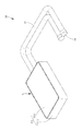
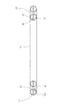
本発明の第1実施形態において、同じ管路が気流流路および液流流路に仕切られた還流ヒートパイプ10は蒸発チャンバー11、還流管15、連結キャップ19および放熱部材100から構成される。本明細書は二つの還流管を配置する例について説明を進める。
(First embodiment)
In the first embodiment of the present invention, the
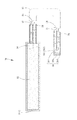
図1から図5に示したのは第1実施形態による同じ管路が気流流路および液流流路に仕切られた還流ヒートパイプ10である。
1 to 5 show a
蒸発チャンバー11は、ハウジング111、ハウジング111内に配置された毛細管材12およびハウジング111内に注入された作動液13を有する。毛細管材12はハウジング111に充満せず、ハウジング111との間に蒸気空間14を形成する。
ハウジング111は蓋1111および格納ケース1112からなる。毛細管材12は格納ケース1112内に格納される。蓋1111は格納ケース1112に被さる。格納ケース1112は周りに形成された四つの側壁と、側壁に形成された穿孔1113とを有する。穿孔1113および蒸発空間14は相互に繋がるように同じ側に位置する。還流管15は格納ケース1112の穿孔1113に差し込まれる。
The
The
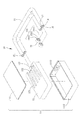
本実施形態において、毛細管材12は銅粉末の焼結によって成形され、複数の流路121を有する。複数の流路121の開口部122は蒸発空間14に繋がる。毛細管材はさらに複数の流路121の開口部122と同じ側から外側の所定距離まで伸びていく延長部123を有する。
In the present embodiment, the
本実施形態において、作動液13は純水からなり、蒸発チャンバー11に注入され、毛細管材12に吸着し、かつ還流管15の一部分に存在する。
In the present embodiment, the
還流管15は、一端が接続端151となり、別の一端が嵌合端152となる。接続端151はハウジング111の穿孔1113に差し込まれてハウジング111内の空間に繋がる。還流管15は内部にスペーサー16を有する。本実施形態において、スペーサー16は板状を呈し、還流管15を気流流路17および液流流路18に仕切る。気流流路17および液流流路18は還流管15内に相互に連絡しない。スペーサー16を製作する際、スペーサー16および還流管15は一体成型されてもよい。
毛細管材12の延長部123は還流管15の液流流路18の形に対応するように配置される。本実施形態において、還流管15の液流流路18は半円形を呈する。毛細管材12の延長部123は還流管15の液流流路18内の所定長さまで入り込んで蒸発チャンバー14と液流流路18の間の流路を遮断し、図5に示すように気体作動液が液流流路18へ流入することを抑制することが目的である。延長部123は上述に限定されず、本発明に必須な部材でないため、配置されなくてもよい。
One end of the
The
連結キャップ19は、内側に凹状部191を有する。凹状部191は階段状の穴を呈し、開口端部1911、末端部1912および環状ストッパー1913を有する。開口端部1911の内径は末端部1912の内径より大きい。環状ストッパー1913は開口端部1911と末端部1912との間に形成される。
還流管15の嵌合端152が凹状部191の開口端部1911に差し込まれる際、還流管15の嵌合端152は連結キャップ19の凹状部191の末端部1912に接触せず、環状ストッパー1913に当接して固定されるため、還流管15の嵌合端152と連結キャップ19の凹状部191の末端部1912との間には流動部位192が形成される。連結キャップ19が還流管15の嵌合端152に被さる際、還流管15内の気流流路17および液流流路18は流動部位192によって繋がる。
The
When the
放熱部材100は、還流管15の嵌合端152に隣接するように還流管15の外部に配置される。本実施形態において、放熱部材100は複数のフィンから構成される。
The
以上は本発明の第1実施形態の構造についての説明である。続いて本発明の第1実施形態の作動状態について説明を進める。 The above is the description of the structure of the first embodiment of the present invention. Subsequently, description will be given on the operating state of the first embodiment of the present invention.
還流ヒートパイプ10が作動する際、電子装置などの発熱源(図中未表示)は蒸発チャンバー11の上に配置され、暫く稼働した後、熱エネルギーを生じ、熱伝導方式によって蒸発チャンバー11に伝導させ、同時に毛細管材12へ拡散させる。作動液13の大部分は液体状態で毛細管材12内に保存される。熱エネルギーが毛細管材12に伝導する際、毛細管材12は昇温し、毛細管材12内の液体作動液13に熱エネルギーを十分に吸収させ、蒸発反応を起こして気体作動液13を生成する。
気体作動液13は毛細管材12の複数の流路121の開口部122から蒸発空間14に流入し、集結した後、還流管15の気流流路17を流動し、連結キャップ19の方向に前進し、連結キャップ19に流入する。続いて還流管15の嵌合端152に隣接するように還流管15の外部に配置される放熱部材100は気体作動液13の熱エネルギーを吸収し、同時に空気中に拡散させる。このとき気体作動液13は放熱部材100の冷却作用によって水滴状の液体作動液13を凝結させる。図4に示すように、凝集した水滴状の液体作動液13が多くなると液体弾131を生成する。圧力差によって液体弾131を前進させれば、液体作動液13は蒸発チャンバー11に還流し易くなり、かつ蒸発チャンバー11まで順調に還流して放熱効率を向上させることができる。このような循環作用により電子装置の熱エネルギーを持続的に誘導し、良好な放熱効果を達成することができる。
When the
The
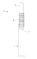
(第2実施形態)
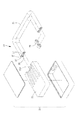
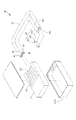
図6から図8に示したのは第2実施形態による同じ管路が気流流路および液流流路に仕切られた還流ヒートパイプ20である。第1実施形態との違いは下記のとおりである。
(Second Embodiment)
6 to 8 show a
第2実施形態において、還流管25は内部に三つのスペーサー26を有する。三つのスペーサー26は断面が人字型であり、還流管25を二つの気流流路27および一つの液流流路28に仕切る。二つの気流流路27および一つの液流流路28は還流管25内に相互に連絡しない。三つのスペーサー26を製作する際、三つのスペーサー26および還流管25は一体成型されてもよい。
In the second embodiment, the
第2実施形態において、毛細管材22は還流管25の液流流路28に対応する延長部223を有する。図8に示すように、延長部223は扇形を呈し、液流流路28内の所定長さまで入り込んで蒸発チャンバー24と液流流路28の間の流路を遮断し、気体作動液が液流流路28へ流入することを抑制することができる。延長部223は上述に限定されず、本発明に必要な部材でないため、配置されなくてもよい。
In the second embodiment, the
上述したとおり、還流管25は三つのスペーサー26によって二つの気流流路27および一つの液流流路28に仕切られ、気流流路28内の液体作動液13に液体弾131を生成させ、圧力差によって液体弾131を前進させることができるため、液体作動液13は蒸発チャンバー21に順調に還流し、放熱効率を向上させることができる。
As described above, the
第2実施形態のほかの構造および達成できる効果は第1実施形態と同じであるため、詳細な説明を省略する。 Since the other structures and effects that can be achieved in the second embodiment are the same as those in the first embodiment, a detailed description thereof will be omitted.
(第3実施形態)
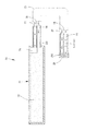
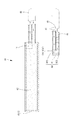
図9および図10に示したのは第3実施形態による同じ管路が気流流路および液流流路に仕切られた還流ヒートパイプ30である。第1実施形態との違いは下記のとおりである。
(Third embodiment)
9 and 10 show a
第3実施形態において、スペーサー36は板状を呈し、還流管35を気流流路37および液流流路38に仕切り、長さが還流管35の長さより小さい。還流管35の接続端351と嵌合端352とが繋がれば嵌合端352の端部から奥へ凹む空間353が形成される。
連結キャップ39は直径の比較的大きい円形底部391、直径の比較的小さい円形頂部392および底部391と頂部392との間に形成された環状ストッパー393を有する。連結キャップ39は頂部392が嵌合端352の奥に入り込む空間353内に嵌まり込み、頂部392から嵌合端352の奥に入り込む空間353までの範囲が流動部位394となる。還流管35の嵌合端352は連結キャップ39の環状ストッパー393に当接して固定される。
In the third embodiment, the
The connecting
第3実施形態において、毛細管材32は格納ケース3112内に格納され、複数の流路321を有するが、延長部は配置されない。複数の流路321の開口部322は蒸発空間34に繋がる。
In the third embodiment, the
第3実施形態のほかの構造および達成できる効果は第1実施形態と同じであるため、詳細な説明を省略する。 Since the other structures and effects that can be achieved in the third embodiment are the same as those in the first embodiment, detailed description thereof is omitted.
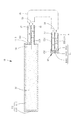
(第4実施形態)
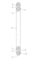
図11および図12に示したのは第4実施形態による同じ管路が気流流路および液流流路に仕切られた還流ヒートパイプ40である。第1実施形態との違いは下記のとおりである。
(Fourth embodiment)
11 and 12 show a
第4実施形態において、還流管45は内部に三つのスペーサー46を有する。三つのスペーサー46は断面が人字型であり、還流管45を二つの気流流路47および一つの液流流路48に仕切り、長さが還流管45の長さより小さい。還流管45は嵌合端452の端部から奥に凹む空間453を有する。
連結キャップ49は直径の比較的大きい円形底部491、直径の比較的小さい円形頂部492および底部491と頂部492との間に形成された環状ストッパー493を有する。連結キャップ49は頂部492が嵌合端452の端部から奥に凹む空間453内に嵌まり込み、頂部492から嵌合端452の端部から奥に凹む空間453までの範囲が流動部位494となる。還流管45の嵌合端452は連結キャップ49の環状ストッパー493に当接して固定される。
In the fourth embodiment, the
The
第4実施形態において、毛細管材42は格納ケース4112内に格納され、複数の流路421を有するが、延長部は配置されない。複数の流路421の開口部422は蒸発空間44に繋がる。
In the fourth embodiment, the
第4実施形態のほかの構造および達成できる効果は第1実施形態と同じであるため、詳細な説明を省略する。 Since the other structures and effects that can be achieved in the fourth embodiment are the same as those in the first embodiment, a detailed description thereof will be omitted.
上述したとおり、本発明は還流管15にスペーサー16を配置し、還流管15を気流流路17および液流流路18に仕切り、還流管15の端部に連結キャップ19を嵌め込むことによって気流流路17および液流流路18を繋げる流動部位192を構成する。
従来の技術に対し、本発明は連結キャップ19の構造が簡単であり、管体の形を変える必要がないため、製造コストを削減することができる。
As described above, in the present invention, the
Compared with the prior art, the present invention has a simple structure of the connecting
10、20、30、40 還流ヒートパイプ
11、21 蒸発チャンバー
111 ハウジング
1111 蓋
1112、3112、4112 格納ケース
1113 穿孔
12、22、32、42 毛細管材
121、321、421 流路
122、322、422 開口部
123、223、 延長部
13 作動液
131 液体弾
14、24、34、44 蒸発空間
15、25、35、45 還流管
151、351 接続端
152、352、452 嵌合端
16、26、36、46 スペーサー
17、27、37、47 気流流路
18、28、38、48 液流流路
19、29、39、49 連結キャップ
191 凹状部
1911 開口端部
1912 末端部
1913、393、493 環状ストッパー
192、292、394、494 流動部位
353、453 空間
391、491 底部
392、492 頂部
100 放熱部材
10, 20, 30, 40
Claims (5)
前記蒸発チャンバーは、ハウジング、前記ハウジング内に配置された毛細管材および前記ハウジング内に注入された作動液を有し、前記毛細管材は前記ハウジングに充満せず、前記ハウジングとの間に蒸気空間を形成し、
前記還流管は一端が接続端となり、別の一端が嵌合端となり、前記還流管の前記接続端は前記ハウジングに接続されて前記還流管と前記ハウジング内の空間を繋げ、
前記還流管は、内部に少なくとも一つのスペーサーを有し、少なくとも一つの前記スペーサーは前記還流管を二つ以上の流路に仕切り、二つ以上の前記流路は前記還流管内に相互に連絡しない少なくとも一つの気流流路および液流流路と定義され、
前記放熱部材は、前記還流管の前記嵌合端に隣接するように前記還流管の外部に配置され、
前記連結キャップは、前記還流管の前記嵌合端に嵌合され、前記還流管内の少なくとも一つの前記スペーサーに間隔を置いて流動部位を形成し、前記流動部位によって前記還流管内の少なくとも一つの前記気流流路および前記液流流路を繋げることを特徴とする、
同じ管路が気流流路および液流流路に仕切られた還流ヒートパイプ。 Evaporation chamber, reflux pipe, heat radiating member and connecting cap,
The evaporation chamber includes a housing, a capillary material disposed in the housing, and a working fluid injected into the housing, and the capillary material does not fill the housing, and a vapor space is formed between the housing and the housing. Forming,
The reflux pipe has one end serving as a connection end, and another end serving as a fitting end, and the connection end of the reflux pipe is connected to the housing to connect the reflux pipe and the space in the housing,
The reflux pipe has at least one spacer therein, and the at least one spacer partitions the reflux pipe into two or more flow paths, and the two or more flow paths do not communicate with each other in the reflux pipe. Defined as at least one air flow channel and liquid flow channel,
The heat radiating member is disposed outside the reflux pipe so as to be adjacent to the fitting end of the reflux pipe,
The connection cap is fitted to the fitting end of the reflux pipe, forms a flow site at an interval from at least one spacer in the reflux pipe, and at least one of the flow pipes in the reflux pipe is formed by the flow site. The air flow channel and the liquid flow channel are connected,
A reflux heat pipe in which the same pipe is divided into an air flow channel and a liquid flow channel.
Applications Claiming Priority (2)
| Application Number | Priority Date | Filing Date | Title |
|---|---|---|---|
| TW107114328 | 2018-04-26 | ||
| TW107114328A TWI645153B (en) | 2018-04-26 | 2018-04-26 | The same tube is divided into a steam flow channel and a liquid flow channel loop heat pipe |
Publications (1)
| Publication Number | Publication Date |
|---|---|
| JP2019190812A true JP2019190812A (en) | 2019-10-31 |
Family
ID=65431731
Family Applications (1)
| Application Number | Title | Priority Date | Filing Date |
|---|---|---|---|
| JP2018117824A Pending JP2019190812A (en) | 2018-04-26 | 2018-06-21 | Recirculation heat pipe in which same pipe line is partitioned into air current passage and fluid current passage |
Country Status (3)
| Country | Link |
|---|---|
| US (1) | US20190331430A1 (en) |
| JP (1) | JP2019190812A (en) |
| TW (1) | TWI645153B (en) |
Families Citing this family (2)
| Publication number | Priority date | Publication date | Assignee | Title |
|---|---|---|---|---|
| US20220128311A1 (en) * | 2020-10-22 | 2022-04-28 | Asia Vital Components Co., Ltd | Vapor-phase/liquid-phase fluid heat exchange uni |
| TWI779985B (en) * | 2022-01-10 | 2022-10-01 | 長聖儀器股份有限公司 | Liquid-vapor composite cooling system |
Citations (11)
| Publication number | Priority date | Publication date | Assignee | Title |
|---|---|---|---|---|
| US4593539A (en) * | 1984-04-13 | 1986-06-10 | Sueddeutsche Kuehlerfabrik Julius Fr. Behr Gmbh & Co. Kg | Evaporator, in particular for automotive air conditioning systems |
| JPS63318493A (en) * | 1987-06-23 | 1988-12-27 | Akutoronikusu Kk | Capillary heat pipe of loop type |
| JPH01111954U (en) * | 1988-01-14 | 1989-07-27 | ||
| US4883116A (en) * | 1989-01-31 | 1989-11-28 | The United States Of America As Represented By The Administrator Of The National Aeronautics And Space Administration | Ceramic heat pipe wick |
| JPH02263097A (en) * | 1989-04-03 | 1990-10-25 | Japan Gore Tex Inc | Heat transfer pipe |
| US20020195230A1 (en) * | 2001-06-22 | 2002-12-26 | Li Jia Hao | Heat exchange structure of loop type heat pipe |
| US20050178532A1 (en) * | 2004-02-18 | 2005-08-18 | Huang Meng-Cheng | Structure for expanding thermal conducting performance of heat sink |
| US6971400B1 (en) * | 2004-04-29 | 2005-12-06 | Bowman Dennis E | Air gap apparatus |
| KR101167985B1 (en) * | 2011-08-24 | 2012-07-23 | 박지오 | Zigzag flow tube evaporator |
| KR20130016999A (en) * | 2011-08-09 | 2013-02-19 | 박지오 | Evaporator having a defrosting heater installed in a tube and method for manufacturing the same |
| CN106091761A (en) * | 2016-07-29 | 2016-11-09 | 苏州聚力电机有限公司 | A kind of loop type heat pipe and organize connecting portion end cap enclosed construction |
Family Cites Families (11)
| Publication number | Priority date | Publication date | Assignee | Title |
|---|---|---|---|---|
| US3750745A (en) * | 1970-07-06 | 1973-08-07 | R Moore | High heat flux heat pipe |
| DE4240082C1 (en) * | 1992-11-28 | 1994-04-21 | Erno Raumfahrttechnik Gmbh | Heat pipe |
| US5704415A (en) * | 1994-11-25 | 1998-01-06 | Nippon Light Metal Co. Ltd. | Winding small tube apparatus and manufacturing method thereof |
| TW407455B (en) * | 1997-12-09 | 2000-10-01 | Diamond Electric Mfg | Heat pipe and its processing method |
| TW506523U (en) * | 2002-03-29 | 2002-10-11 | Hon Hai Prec Ind Co Ltd | Heat pipe |
| US7324341B2 (en) * | 2005-09-22 | 2008-01-29 | Delphi Technologies, Inc. | Electronics assembly and heat pipe device |
| CN201104143Y (en) * | 2007-02-05 | 2008-08-20 | 中山大学 | Multicenter self-adjusting recirculation loop heat pipe device |
| CN201145246Y (en) * | 2007-07-11 | 2008-11-05 | 李建胜 | Light emitting diode component |
| TWI539269B (en) * | 2015-01-28 | 2016-06-21 | 訊凱國際股份有限公司 | Heat sink module and thermosiphon heat sink |
| WO2017068677A1 (en) * | 2015-10-22 | 2017-04-27 | 株式会社丸三電機 | Pipe member, heat pipe, and cooling device |
| US11320211B2 (en) * | 2017-04-11 | 2022-05-03 | Cooler Master Co., Ltd. | Heat transfer device |
-
2018
- 2018-04-26 TW TW107114328A patent/TWI645153B/en active
- 2018-06-21 JP JP2018117824A patent/JP2019190812A/en active Pending
- 2018-07-12 US US16/033,497 patent/US20190331430A1/en not_active Abandoned
Patent Citations (11)
| Publication number | Priority date | Publication date | Assignee | Title |
|---|---|---|---|---|
| US4593539A (en) * | 1984-04-13 | 1986-06-10 | Sueddeutsche Kuehlerfabrik Julius Fr. Behr Gmbh & Co. Kg | Evaporator, in particular for automotive air conditioning systems |
| JPS63318493A (en) * | 1987-06-23 | 1988-12-27 | Akutoronikusu Kk | Capillary heat pipe of loop type |
| JPH01111954U (en) * | 1988-01-14 | 1989-07-27 | ||
| US4883116A (en) * | 1989-01-31 | 1989-11-28 | The United States Of America As Represented By The Administrator Of The National Aeronautics And Space Administration | Ceramic heat pipe wick |
| JPH02263097A (en) * | 1989-04-03 | 1990-10-25 | Japan Gore Tex Inc | Heat transfer pipe |
| US20020195230A1 (en) * | 2001-06-22 | 2002-12-26 | Li Jia Hao | Heat exchange structure of loop type heat pipe |
| US20050178532A1 (en) * | 2004-02-18 | 2005-08-18 | Huang Meng-Cheng | Structure for expanding thermal conducting performance of heat sink |
| US6971400B1 (en) * | 2004-04-29 | 2005-12-06 | Bowman Dennis E | Air gap apparatus |
| KR20130016999A (en) * | 2011-08-09 | 2013-02-19 | 박지오 | Evaporator having a defrosting heater installed in a tube and method for manufacturing the same |
| KR101167985B1 (en) * | 2011-08-24 | 2012-07-23 | 박지오 | Zigzag flow tube evaporator |
| CN106091761A (en) * | 2016-07-29 | 2016-11-09 | 苏州聚力电机有限公司 | A kind of loop type heat pipe and organize connecting portion end cap enclosed construction |
Also Published As
| Publication number | Publication date |
|---|---|
| TWI645153B (en) | 2018-12-21 |
| TW201945681A (en) | 2019-12-01 |
| US20190331430A1 (en) | 2019-10-31 |
Similar Documents
| Publication | Publication Date | Title |
|---|---|---|
| JP2019184219A (en) | Reflow heat pipe with liquid bullet pipe conduit | |
| US7316264B2 (en) | Heat pipe | |
| TWM526264U (en) | Liquid-cooled heat dissipation device and heat dissipation structure thereof | |
| TWI776497B (en) | Three-dimensional heat dissipating device | |
| JP2019190815A (en) | Recirculation heat pipe in which capillary member is put in part of cooling section | |
| CN215500211U (en) | Heat sink device | |
| US10240873B2 (en) | Joint assembly of vapor chambers | |
| JP2016050682A (en) | Sheet-type heat pipe | |
| JP2019190812A (en) | Recirculation heat pipe in which same pipe line is partitioned into air current passage and fluid current passage | |
| KR101097390B1 (en) | Heat pipe with double pipe structure | |
| CN107306486B (en) | Integrated heat dissipation device | |
| JP3156954U (en) | Support structure for flat plate heat pipe | |
| JP4080479B2 (en) | Liquid cooler cooler | |
| JP2019190811A (en) | Recirculation heat pipe with different bore diameters | |
| TWM638398U (en) | 3D vapor chamber | |
| US20200309465A1 (en) | Heat exchange device | |
| US20120255716A1 (en) | Heat dissipation device and manufacturing method thereof | |
| TWM523894U (en) | Heat dissipation structure and water-cooling device comprising the same | |
| JP3210120U (en) | Capillary structure and loop heat pipe having the capillary structure | |
| JP2019194515A (en) | Reflux vapor chamber | |
| JP3209772U (en) | Loop heat pipe structure | |
| CN106793671B (en) | Heat radiation unit | |
| TWI828451B (en) | 3d vapor chamber | |
| JP2013120053A (en) | Heat pipe | |
| WO2017082127A1 (en) | Electronic equipment cooling device |
Legal Events
| Date | Code | Title | Description |
|---|---|---|---|
| A621 | Written request for application examination |
Free format text: JAPANESE INTERMEDIATE CODE: A621 Effective date: 20180622 |
|
| A131 | Notification of reasons for refusal |
Free format text: JAPANESE INTERMEDIATE CODE: A131 Effective date: 20190611 |
|
| A02 | Decision of refusal |
Free format text: JAPANESE INTERMEDIATE CODE: A02 Effective date: 20200204 |