JP2019124329A - トルク変動抑制装置、トルクコンバータ、及び動力伝達装置 - Google Patents
トルク変動抑制装置、トルクコンバータ、及び動力伝達装置 Download PDFInfo
- Publication number
- JP2019124329A JP2019124329A JP2018006968A JP2018006968A JP2019124329A JP 2019124329 A JP2019124329 A JP 2019124329A JP 2018006968 A JP2018006968 A JP 2018006968A JP 2018006968 A JP2018006968 A JP 2018006968A JP 2019124329 A JP2019124329 A JP 2019124329A
- Authority
- JP
- Japan
- Prior art keywords
- torque
- rotating body
- torque fluctuation
- centrifuge
- cam
- Prior art date
- Legal status (The legal status is an assumption and is not a legal conclusion. Google has not performed a legal analysis and makes no representation as to the accuracy of the status listed.)
- Pending
Links
Images


Classifications
-
- F—MECHANICAL ENGINEERING; LIGHTING; HEATING; WEAPONS; BLASTING
- F16—ENGINEERING ELEMENTS AND UNITS; GENERAL MEASURES FOR PRODUCING AND MAINTAINING EFFECTIVE FUNCTIONING OF MACHINES OR INSTALLATIONS; THERMAL INSULATION IN GENERAL
- F16F—SPRINGS; SHOCK-ABSORBERS; MEANS FOR DAMPING VIBRATION
- F16F15/00—Suppression of vibrations in systems; Means or arrangements for avoiding or reducing out-of-balance forces, e.g. due to motion
- F16F15/10—Suppression of vibrations in rotating systems by making use of members moving with the system
- F16F15/14—Suppression of vibrations in rotating systems by making use of members moving with the system using masses freely rotating with the system, i.e. uninvolved in transmitting driveline torque, e.g. rotative dynamic dampers
- F16F15/1407—Suppression of vibrations in rotating systems by making use of members moving with the system using masses freely rotating with the system, i.e. uninvolved in transmitting driveline torque, e.g. rotative dynamic dampers the rotation being limited with respect to the driving means
- F16F15/1464—Masses connected to driveline by a kinematic mechanism or gear system
-
- F—MECHANICAL ENGINEERING; LIGHTING; HEATING; WEAPONS; BLASTING
- F16—ENGINEERING ELEMENTS AND UNITS; GENERAL MEASURES FOR PRODUCING AND MAINTAINING EFFECTIVE FUNCTIONING OF MACHINES OR INSTALLATIONS; THERMAL INSULATION IN GENERAL
- F16F—SPRINGS; SHOCK-ABSORBERS; MEANS FOR DAMPING VIBRATION
- F16F15/00—Suppression of vibrations in systems; Means or arrangements for avoiding or reducing out-of-balance forces, e.g. due to motion
- F16F15/10—Suppression of vibrations in rotating systems by making use of members moving with the system
- F16F15/12—Suppression of vibrations in rotating systems by making use of members moving with the system using elastic members or friction-damping members, e.g. between a rotating shaft and a gyratory mass mounted thereon
- F16F15/131—Suppression of vibrations in rotating systems by making use of members moving with the system using elastic members or friction-damping members, e.g. between a rotating shaft and a gyratory mass mounted thereon the rotating system comprising two or more gyratory masses
- F16F15/13164—Suppression of vibrations in rotating systems by making use of members moving with the system using elastic members or friction-damping members, e.g. between a rotating shaft and a gyratory mass mounted thereon the rotating system comprising two or more gyratory masses characterised by the supporting arrangement of the damper unit
-
- F—MECHANICAL ENGINEERING; LIGHTING; HEATING; WEAPONS; BLASTING
- F16—ENGINEERING ELEMENTS AND UNITS; GENERAL MEASURES FOR PRODUCING AND MAINTAINING EFFECTIVE FUNCTIONING OF MACHINES OR INSTALLATIONS; THERMAL INSULATION IN GENERAL
- F16F—SPRINGS; SHOCK-ABSORBERS; MEANS FOR DAMPING VIBRATION
- F16F15/00—Suppression of vibrations in systems; Means or arrangements for avoiding or reducing out-of-balance forces, e.g. due to motion
- F16F15/10—Suppression of vibrations in rotating systems by making use of members moving with the system
- F16F15/14—Suppression of vibrations in rotating systems by making use of members moving with the system using masses freely rotating with the system, i.e. uninvolved in transmitting driveline torque, e.g. rotative dynamic dampers
- F16F15/1407—Suppression of vibrations in rotating systems by making use of members moving with the system using masses freely rotating with the system, i.e. uninvolved in transmitting driveline torque, e.g. rotative dynamic dampers the rotation being limited with respect to the driving means
- F16F15/145—Masses mounted with play with respect to driving means thus enabling free movement over a limited range
-
- F—MECHANICAL ENGINEERING; LIGHTING; HEATING; WEAPONS; BLASTING
- F16—ENGINEERING ELEMENTS AND UNITS; GENERAL MEASURES FOR PRODUCING AND MAINTAINING EFFECTIVE FUNCTIONING OF MACHINES OR INSTALLATIONS; THERMAL INSULATION IN GENERAL
- F16H—GEARING
- F16H45/00—Combinations of fluid gearings for conveying rotary motion with couplings or clutches
- F16H45/02—Combinations of fluid gearings for conveying rotary motion with couplings or clutches with mechanical clutches for bridging a fluid gearing of the hydrokinetic type
-
- F—MECHANICAL ENGINEERING; LIGHTING; HEATING; WEAPONS; BLASTING
- F16—ENGINEERING ELEMENTS AND UNITS; GENERAL MEASURES FOR PRODUCING AND MAINTAINING EFFECTIVE FUNCTIONING OF MACHINES OR INSTALLATIONS; THERMAL INSULATION IN GENERAL
- F16F—SPRINGS; SHOCK-ABSORBERS; MEANS FOR DAMPING VIBRATION
- F16F2230/00—Purpose; Design features
- F16F2230/0052—Physically guiding or influencing
- F16F2230/0064—Physically guiding or influencing using a cam
-
- F—MECHANICAL ENGINEERING; LIGHTING; HEATING; WEAPONS; BLASTING
- F16—ENGINEERING ELEMENTS AND UNITS; GENERAL MEASURES FOR PRODUCING AND MAINTAINING EFFECTIVE FUNCTIONING OF MACHINES OR INSTALLATIONS; THERMAL INSULATION IN GENERAL
- F16H—GEARING
- F16H45/00—Combinations of fluid gearings for conveying rotary motion with couplings or clutches
- F16H45/02—Combinations of fluid gearings for conveying rotary motion with couplings or clutches with mechanical clutches for bridging a fluid gearing of the hydrokinetic type
- F16H2045/0221—Combinations of fluid gearings for conveying rotary motion with couplings or clutches with mechanical clutches for bridging a fluid gearing of the hydrokinetic type with damping means
- F16H2045/0263—Combinations of fluid gearings for conveying rotary motion with couplings or clutches with mechanical clutches for bridging a fluid gearing of the hydrokinetic type with damping means the damper comprising a pendulum
Abstract
Description
トルクコンバータ1は、フロントカバー2と、トルクコンバータ本体3と、ロックアップ装置4と、出力ハブ5と、を有している。フロントカバー2にはエンジン100からトルクが入力される。トルクコンバータ本体3は、フロントカバー2に連結されたインペラ7と、タービン8と、ステータ(図示せず)と、を有している。タービン8は出力ハブ5に連結されており、出力ハブ5の内周部には、トランスミッションの入力軸(図示せず)がスプラインによって係合可能である。
ロックアップ装置4は、クラッチ部や、油圧によって作動するピストン等を有し、ロックアップオン状態と、ロックアップオフ状態と、を取り得る。ロックアップオン状態では、フロントカバー2に入力されたトルクは、トルクコンバータ本体3を介さずに、ロックアップ装置4を介して出力ハブ5に伝達される。一方、ロックアップオフ状態では、フロントカバー2に入力されたトルクは、トルクコンバータ本体3を介して出力ハブ5に伝達される。
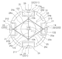
図3〜図5にトルク変動抑制装置14を示している。図3は、ハブフランジ12及びトルク変動抑制装置14を模式的に示した正面図である。図4は図3の一部を詳細に示した図、図5は図4をA方向から視た図である。なお、図3及び図4は一方(手前側)のイナーシャリングを取り外して示している。
第1及び第2イナーシャリング201,202は、それぞれ連続した円環状に形成された所定の厚みを有するプレートであり、図5に示すように、ハブフランジ12を挟んでハブフランジ12の軸方向両側に所定の隙間をあけて配置されている。すなわち、ハブフランジ12と第1及び第2イナーシャリング201,202とは、軸方向に並べて配置されている。第1及び第2イナーシャリング201,202は、ハブフランジ12の回転軸と同じ回転軸を有し、ハブフランジ12とともに回転可能で、かつハブフランジ12に対して相対回転自在である。
ハブフランジ12は、円板状に形成され、内周部が前述のように出力ハブ5に連結されている。ハブフランジ12の外周部には、外周側にさらに突出し、円周方向に所定の幅を有する4つの突起部121が形成されている。突起部121の円周方向の中央部には、所定の幅の凹部122が形成されている。凹部122は、径方向外方に開くように形成され、所定の深さを有している。
遠心子21は、2個の第1遠心子211と、2個の第2遠心子212と、を有している。以下の説明では、4個の遠心子211,212を含んで単に「遠心子21」と記す場合もある。2個の第1遠心子211は対向する位置、すなわち180°の間隔をあけて配置されている。また、2個の第2遠心子212も同様に180°の間隔をあけて配置されている。第1遠心子211と第2遠心子212とは90°の間隔で配置されている。
ピン27の両端は遠心子21に固定されている。
制限機構23は、対向して配置された2個の第2遠心子212が径方向外側に移動するのを制限するための機構である。具体的には、制限機構23は、後述するカム機構22において、カム31とカムフォロアとしてのコロ30とが非接触状態になるように、第2遠心子212の移動を制限する。
カム機構22は、カムフォロアとしての円筒状のコロ30と、遠心子21の外周面21cであるカム31と、から構成されている。コロ30は、リベット203の胴部の外周に嵌めこまれている。すなわち、コロ30はリベット203に支持されている。なお、コロ30は、リベット203に対して回転自在に装着されているのが好ましいが、回転不能であってもよい。カム31は、コロ30が当接する円弧状の面であり、ハブフランジ12と第1及び第2イナーシャリング201,202とが所定の角度範囲で相対回転した際には、コロ30はこのカム31に沿って移動する。
図6を用いて、カム機構22の作動(トルク変動の抑制)について説明する。なお、以下の説明では、第1及び第2イナーシャリング201,202を、単に「イナーシャリング20」と記す場合もある。
図7は、トルク変動抑制特性の一例を示す図である。横軸は回転数、縦軸はトルク変動(回転速度変動)である。特性Q1はトルク変動を抑制するための装置が設けられていない場合、特性Q2はカム機構を有さない従来のダイナミックダンパ装置が設けられた場合、特性Q3は本実施形態のトルク変動抑制装置14が設けられた場合を示している。なお、特性Q3は4つのすべての遠心子21を作動させた場合の特性である。
本発明は以上のような実施形態に限定されるものではなく、本発明の範囲を逸脱することなく種々の変形又は修正が可能である。
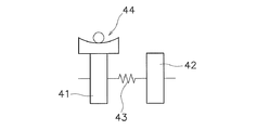
以上のようなトルク変動抑制装置を、トルクコンバータや他の動力伝達装置に適用する場合、種々の配置が可能である。以下に、トルクコンバータや他の動力伝達装置の模式図を利用して、具体的な適用例について説明する。
11 入力側回転体
12,42 ハブフランジ(回転体)
122 凹部
14 トルク変動抑制装置
20,201,202 イナーシャリング(質量体)
21 遠心子(抗力機構の一部)
211 第1遠心子
212 第2遠心子
22 カム機構(抗力機構の一部)
23 制限機構
30 コロ(カムフォロア)
31 カム
41 入力側回転体
43 ダンパ
50 フライホイール
51,61 第1慣性体
52 第2慣性体
54,62 クラッチ装置
Claims (10)
- トルクが入力される回転体のトルク変動を抑制するトルク変動抑制装置であって、
前記回転体とともに回転可能であり、かつ前記回転体に対して相対回転自在に配置された質量体と、
前記回転体と前記質量体との間に回転方向における相対変位が生じたときに、前記相対変位が小さくなる方向の円周方向力を発生する複数の抗力機構と、
前記複数の抗力機構のうちから選択された1以上の抗力機構の作動を制限する制限機構と、
を備えたトルク変動抑制装置。 - 前記抗力機構は、
前記回転体及び前記質量体の回転による遠心力を受けるように配置された複数の遠心子と、
前記遠心子に作用する遠心力を前記円周方向力に変換するカム機構と、
を有し、
前記制限機構は前記遠心子の作動を制限する、
請求項1に記載のトルク変動抑制装置。 - 前記回転体は複数の気筒を有するエンジンからのトルクが入力されるものであり、
前記制限機構は、前記複数の気筒のうちの休止している気筒数に応じた個数の遠心子の作動を制限する、
請求項1又は2に記載のトルク変動抑制装置。 - 前記制限機構は、前記遠心子の径方向外側への移動を制限する、請求項2又は3に記載のトルク変動抑制装置。
- 前記複数の遠心子は、前記回転体の回転中心を挟んで対向して配置されており、
前記制限機構は、対向する前記遠心子の作動を制限する、
請求項2からの4のいずれかに記載のトルク変動抑制装置。 - 前記カム機構は、
前記質量体及び前記遠心子の一方に設けられたカムと、
前記質量体及び前記遠心子の他方に設けられ前記カムに沿って移動するカムフォロアと、を有し、
前記制限機構は、前記カムとカムフォロアとを非接触にする、
請求項2から5のいずれかに記載のトルク変動抑制装置。 - 前記回転体は、外周面に径方向外方に開く複数の凹部を有し、
前記遠心子は前記凹部に収容されている、
請求項2から6のいずれかに記載のトルク変動抑制装置。 - 前記質量体は、前記回転体を挟んで対向して配置された第1イナーシャリング及び第2イナーシャリングと、前記第1イナーシャリングと前記第2イナーシャリングとを相対回転不能に連結するピンと、を有し、
前記遠心子は、前記回転体の外周部でかつ前記ピンの内周側において前記第1イナーシャリングと前記第2イナーシャリングとの軸方向間に配置されており、
前記カムフォロアは、内部に前記ピンが軸方向に貫通する孔を有する円筒状のコロであり、
前記カムは、前記遠心子に形成されて前記カムフォロアに当接し、前記回転体と前記質量体との間の回転方向における相対変位量に応じて前記円周方向力が変化するような形状を有する、
請求項2から7のいずれかに記載のトルク変動抑制装置。 - エンジンとトランスミッションとの間に配置されるトルクコンバータであって、
前記エンジンからのトルクが入力される入力側回転体と、
前記トランスミッションにトルクを出力する出力側回転体と、
前記入力側回転体と前記タービンとの間に配置されたダンパと、
請求項1から8のいずれかに記載のトルク変動抑制装置と、
を備えたトルクコンバータ。 - 回転軸を中心に回転する第1慣性体と、前記回転軸を中心に回転し前記第1慣性体と相対回転自在な第2慣性体と、前記第1慣性体と前記第2慣性体との間に配置されたダンパと、を有するフライホイールと、
前記フライホイールの前記第2慣性体に設けられたクラッチ装置と、
請求項1から9のいずれかに記載のトルク変動抑制装置と、
を備えた動力伝達装置。
Priority Applications (3)
| Application Number | Priority Date | Filing Date | Title |
|---|---|---|---|
| JP2018006968A JP2019124329A (ja) | 2018-01-19 | 2018-01-19 | トルク変動抑制装置、トルクコンバータ、及び動力伝達装置 |
| US16/217,745 US10808796B2 (en) | 2018-01-19 | 2018-12-12 | Torque fluctuation inhibiting device, torque converter and power transmission device |
| CN201811598904.3A CN110056605A (zh) | 2018-01-19 | 2018-12-26 | 扭矩变动抑制装置、液力变矩器及动力传递装置 |
Applications Claiming Priority (1)
| Application Number | Priority Date | Filing Date | Title |
|---|---|---|---|
| JP2018006968A JP2019124329A (ja) | 2018-01-19 | 2018-01-19 | トルク変動抑制装置、トルクコンバータ、及び動力伝達装置 |
Publications (2)
| Publication Number | Publication Date |
|---|---|
| JP2019124329A true JP2019124329A (ja) | 2019-07-25 |
| JP2019124329A5 JP2019124329A5 (ja) | 2019-09-05 |
Family
ID=67299831
Family Applications (1)
| Application Number | Title | Priority Date | Filing Date |
|---|---|---|---|
| JP2018006968A Pending JP2019124329A (ja) | 2018-01-19 | 2018-01-19 | トルク変動抑制装置、トルクコンバータ、及び動力伝達装置 |
Country Status (3)
| Country | Link |
|---|---|
| US (1) | US10808796B2 (ja) |
| JP (1) | JP2019124329A (ja) |
| CN (1) | CN110056605A (ja) |
Cited By (2)
| Publication number | Priority date | Publication date | Assignee | Title |
|---|---|---|---|---|
| JP2019163817A (ja) * | 2018-03-20 | 2019-09-26 | 株式会社エクセディ | 動力伝達装置 |
| JP2019163815A (ja) * | 2018-03-20 | 2019-09-26 | 株式会社エクセディ | 動力伝達装置 |
Families Citing this family (3)
| Publication number | Priority date | Publication date | Assignee | Title |
|---|---|---|---|---|
| JP6764430B2 (ja) * | 2018-02-21 | 2020-09-30 | 株式会社エクセディ | トルク変動抑制装置、トルクコンバータ、及び動力伝達装置 |
| US10955025B2 (en) * | 2018-05-31 | 2021-03-23 | GM Global Technology Operations LLC | Vehicle powertrain variable vibration absorber assembly |
| JP7376291B2 (ja) * | 2019-09-13 | 2023-11-08 | 株式会社エクセディ | トルク変動抑制装置、及び動力伝達装置 |
Citations (4)
| Publication number | Priority date | Publication date | Assignee | Title |
|---|---|---|---|---|
| JP2011185307A (ja) * | 2010-03-04 | 2011-09-22 | Toyota Motor Corp | ダンパ装置および車両制御装置 |
| JP2016142404A (ja) * | 2015-02-05 | 2016-08-08 | 富士重工業株式会社 | トルクコンバータ |
| JP2017053467A (ja) * | 2015-09-11 | 2017-03-16 | 株式会社エクセディ | トルク変動抑制装置、トルクコンバータ、及び動力伝達装置 |
| JP2017072167A (ja) * | 2015-10-06 | 2017-04-13 | 株式会社エクセディ | トルク変動抑制装置、トルクコンバータ、及び動力伝達装置 |
-
2018
- 2018-01-19 JP JP2018006968A patent/JP2019124329A/ja active Pending
- 2018-12-12 US US16/217,745 patent/US10808796B2/en active Active
- 2018-12-26 CN CN201811598904.3A patent/CN110056605A/zh active Pending
Patent Citations (4)
| Publication number | Priority date | Publication date | Assignee | Title |
|---|---|---|---|---|
| JP2011185307A (ja) * | 2010-03-04 | 2011-09-22 | Toyota Motor Corp | ダンパ装置および車両制御装置 |
| JP2016142404A (ja) * | 2015-02-05 | 2016-08-08 | 富士重工業株式会社 | トルクコンバータ |
| JP2017053467A (ja) * | 2015-09-11 | 2017-03-16 | 株式会社エクセディ | トルク変動抑制装置、トルクコンバータ、及び動力伝達装置 |
| JP2017072167A (ja) * | 2015-10-06 | 2017-04-13 | 株式会社エクセディ | トルク変動抑制装置、トルクコンバータ、及び動力伝達装置 |
Cited By (2)
| Publication number | Priority date | Publication date | Assignee | Title |
|---|---|---|---|---|
| JP2019163817A (ja) * | 2018-03-20 | 2019-09-26 | 株式会社エクセディ | 動力伝達装置 |
| JP2019163815A (ja) * | 2018-03-20 | 2019-09-26 | 株式会社エクセディ | 動力伝達装置 |
Also Published As
| Publication number | Publication date |
|---|---|
| CN110056605A (zh) | 2019-07-26 |
| US10808796B2 (en) | 2020-10-20 |
| US20190226553A1 (en) | 2019-07-25 |
Similar Documents
| Publication | Publication Date | Title |
|---|---|---|
| JP2019124329A (ja) | トルク変動抑制装置、トルクコンバータ、及び動力伝達装置 | |
| JP6534589B2 (ja) | トルク変動抑制装置、トルクコンバータ、及び動力伝達装置 | |
| WO2017029931A1 (ja) | トルク変動抑制装置、トルクコンバータ、及び動力伝達装置 | |
| JP6653538B2 (ja) | トルク変動抑制装置、トルクコンバータ、及び動力伝達装置 | |
| JP6709765B2 (ja) | トルク変動抑制装置、トルクコンバータ、及び動力伝達装置 | |
| JP6757680B2 (ja) | トルク変動抑制装置、トルクコンバータ、及び動力伝達装置 | |
| WO2018150660A1 (ja) | トルク変動抑制装置、トルクコンバータ、及び動力伝達装置 | |
| JP6657041B2 (ja) | トルク変動抑制装置、トルクコンバータ、及び動力伝達装置 | |
| WO2018150777A1 (ja) | トルク変動抑制装置、トルクコンバータ、及び動力伝達装置 | |
| JP2019039456A5 (ja) | ||
| JP6712586B2 (ja) | トルク変動抑制装置、トルクコンバータ、及び動力伝達装置 | |
| JP2019039456A (ja) | トルク変動抑制装置、トルクコンバータ、及び動力伝達装置 | |
| WO2018016212A1 (ja) | トルク変動抑制装置、トルクコンバータ、及び動力伝達装置 | |
| JP6764430B2 (ja) | トルク変動抑制装置、トルクコンバータ、及び動力伝達装置 | |
| JP2021071190A (ja) | トルク変動抑制装置及び動力伝達装置 | |
| JP7300284B2 (ja) | トルク変動抑制装置、及びトルクコンバータ | |
| US11661995B2 (en) | Torque fluctuation inhibiting device and torque converter | |
| JP6656868B2 (ja) | トルク変動抑制装置、トルクコンバータ、及び動力伝達装置 | |
| JP2006162054A5 (ja) | ||
| JP7376291B2 (ja) | トルク変動抑制装置、及び動力伝達装置 | |
| US11428292B2 (en) | Torque fluctuation inhibiting device and torque converter | |
| JP6709764B2 (ja) | トルク変動抑制装置、トルクコンバータ、及び動力伝達装置 | |
| JP6682572B2 (ja) | トルク変動抑制装置 | |
| JP2018096454A (ja) | 振動低減装置 | |
| JP7232667B2 (ja) | トルク変動抑制装置 |
Legal Events
| Date | Code | Title | Description |
|---|---|---|---|
| A621 | Written request for application examination |
Free format text: JAPANESE INTERMEDIATE CODE: A621 Effective date: 20190319 |
|
| A521 | Request for written amendment filed |
Free format text: JAPANESE INTERMEDIATE CODE: A523 Effective date: 20190703 |
|
| A977 | Report on retrieval |
Free format text: JAPANESE INTERMEDIATE CODE: A971007 Effective date: 20200123 |
|
| A131 | Notification of reasons for refusal |
Free format text: JAPANESE INTERMEDIATE CODE: A131 Effective date: 20200128 |
|
| A521 | Request for written amendment filed |
Free format text: JAPANESE INTERMEDIATE CODE: A523 Effective date: 20200318 |
|
| A131 | Notification of reasons for refusal |
Free format text: JAPANESE INTERMEDIATE CODE: A131 Effective date: 20200728 |
|
| A02 | Decision of refusal |
Free format text: JAPANESE INTERMEDIATE CODE: A02 Effective date: 20210209 |