JP2019120141A - ガス昇温用ヒータ装置 - Google Patents
ガス昇温用ヒータ装置 Download PDFInfo
- Publication number
- JP2019120141A JP2019120141A JP2017253236A JP2017253236A JP2019120141A JP 2019120141 A JP2019120141 A JP 2019120141A JP 2017253236 A JP2017253236 A JP 2017253236A JP 2017253236 A JP2017253236 A JP 2017253236A JP 2019120141 A JP2019120141 A JP 2019120141A
- Authority
- JP
- Japan
- Prior art keywords
- gas
- conductor
- exhaust gas
- conductive structure
- temperature
- Prior art date
- Legal status (The legal status is an assumption and is not a legal conclusion. Google has not performed a legal analysis and makes no representation as to the accuracy of the status listed.)
- Granted
Links
- 230000000630 rising effect Effects 0.000 title claims abstract description 7
- 239000004020 conductor Substances 0.000 claims abstract description 93
- 230000002093 peripheral effect Effects 0.000 claims abstract description 90
- 238000010438 heat treatment Methods 0.000 claims abstract description 50
- 239000003054 catalyst Substances 0.000 claims description 22
- 238000000746 purification Methods 0.000 claims description 21
- 239000000126 substance Substances 0.000 claims description 11
- 229910052751 metal Inorganic materials 0.000 claims description 8
- 239000002184 metal Substances 0.000 claims description 8
- 229910000831 Steel Inorganic materials 0.000 claims description 6
- 239000010959 steel Substances 0.000 claims description 6
- 230000004044 response Effects 0.000 claims description 4
- 229910018487 Ni—Cr Inorganic materials 0.000 claims description 3
- 230000003213 activating effect Effects 0.000 claims description 3
- 238000005219 brazing Methods 0.000 claims description 3
- VNNRSPGTAMTISX-UHFFFAOYSA-N chromium nickel Chemical compound [Cr].[Ni] VNNRSPGTAMTISX-UHFFFAOYSA-N 0.000 claims description 3
- -1 iron chromium aluminum Chemical compound 0.000 claims description 3
- 238000009792 diffusion process Methods 0.000 claims description 2
- 238000004804 winding Methods 0.000 claims description 2
- 206010015137 Eructation Diseases 0.000 claims 1
- 239000007789 gas Substances 0.000 description 192
- 239000011295 pitch Substances 0.000 description 16
- 239000013618 particulate matter Substances 0.000 description 12
- 239000000919 ceramic Substances 0.000 description 9
- 239000004745 nonwoven fabric Substances 0.000 description 8
- 238000011144 upstream manufacturing Methods 0.000 description 8
- 230000020169 heat generation Effects 0.000 description 7
- 239000004071 soot Substances 0.000 description 6
- 230000004913 activation Effects 0.000 description 4
- 238000002485 combustion reaction Methods 0.000 description 4
- 238000007599 discharging Methods 0.000 description 3
- MWUXSHHQAYIFBG-UHFFFAOYSA-N nitrogen oxide Inorganic materials O=[N] MWUXSHHQAYIFBG-UHFFFAOYSA-N 0.000 description 3
- QAOWNCQODCNURD-UHFFFAOYSA-L Sulfate Chemical compound [O-]S([O-])(=O)=O QAOWNCQODCNURD-UHFFFAOYSA-L 0.000 description 2
- 230000001154 acute effect Effects 0.000 description 2
- 230000033228 biological regulation Effects 0.000 description 2
- 239000000835 fiber Substances 0.000 description 2
- 230000003647 oxidation Effects 0.000 description 2
- 238000007254 oxidation reaction Methods 0.000 description 2
- BASFCYQUMIYNBI-UHFFFAOYSA-N platinum Chemical compound [Pt] BASFCYQUMIYNBI-UHFFFAOYSA-N 0.000 description 2
- 230000009467 reduction Effects 0.000 description 2
- 230000008929 regeneration Effects 0.000 description 2
- 238000011069 regeneration method Methods 0.000 description 2
- 238000010792 warming Methods 0.000 description 2
- 230000008859 change Effects 0.000 description 1
- 238000006243 chemical reaction Methods 0.000 description 1
- 238000000151 deposition Methods 0.000 description 1
- 230000005611 electricity Effects 0.000 description 1
- 230000001976 improved effect Effects 0.000 description 1
- 230000006872 improvement Effects 0.000 description 1
- 229910052697 platinum Inorganic materials 0.000 description 1
- 230000003014 reinforcing effect Effects 0.000 description 1
- 230000000717 retained effect Effects 0.000 description 1
- 230000008093 supporting effect Effects 0.000 description 1
Images


Abstract
Description
平ら状導電体がジグザグ状に折り曲げられた長手方向に延びる凸部を備えた波状導電体と長手方向に帯状に延びる平ら状導電体とが重ねられて螺旋状に巻き上げられた円筒状成形体の導電構造体,前記導電構造体の内周にリング状に配設された金属製の内周側電極,及び前記導電構造体の外周にリング状に配設された金属製の外周側電極を備えており,
前記導電構造体は,前記波状導電体の前記凸部と前記平ら状導電体との接点が接合されると共に,前記内周側電極と前記外周側電極とに接する前記波状導電体の前記凸部が前記内周側電極と前記外周側電極にそれぞれ接合されており,
前記導電構造体は,前記波状導電体の前記凸部間に延びる柱部と前記平ら状導電体とによって断面三角形状ガス通路が長手方向に延びて周方向に複数個形成されており,
前記導電構造体は,電源から前記内周側電極と前記外周側電極とに通電することによって,電流が前記導電構造体に半径方向に流れてヒータに構成され,前記導電構造体の前記断面三角形状ガス通路を流れる前記ガス体が昇温されることを特徴とするガス昇温用ヒータ装置に関する。
即ち,発熱量をP,電流をI,抵抗値Rとすると,P=I×I×Rである。
2 導電構造体
3 波状導電体
3A 内側極小ピッチ
3B 2段目小ピッチ
3C 3段目中ピッチ
3D 外側大ピッチ
4 平ら状導電体
5 円筒状成形体
7 断面三角形状のガス通路
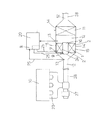
10 エンジン
11 排気ガス浄化装置
12 排気ガス通路
13 温度センサー
15 外周側電極
16 内周側電極
17 凸部
18 柱部
19 接点
20 コントローラ
21 内周部
22 外周部
24 遮蔽板
Claims (9)
- ガス体が流れるガス通路に配設された導電体に通電して前記ガス通路を流れる前記ガス体を加熱して前記ガス体を予め決められた所定の温度に昇温するガス昇温用ヒータ装置において,
平ら状導電体がジグザグ状に折り曲げられた長手方向に延びる凸部を備えた波状導電体と長手方向に帯状に延びる平ら状導電体とが重ねられて螺旋状に巻き上げられた円筒状成形体の導電構造体,前記導電構造体の内周にリング状に配設された金属製の内周側電極,及び前記導電構造体の外周にリング状に配設された金属製の外周側電極を備えており,
前記導電構造体は,前記波状導電体の前記凸部と前記平ら状導電体との接点が接合されると共に,前記内周側電極と前記外周側電極とに接する前記波状導電体の前記凸部が前記内周側電極と前記外周側電極にそれぞれ接合されており,
前記導電構造体は,前記波状導電体の前記凸部間に延びる柱部と前記平ら状導電体とによって断面三角形状ガス通路が長手方向に延びて周方向に複数個形成されており,
前記導電構造体は,電源から前記内周側電極と前記外周側電極とに通電することによって,電流が前記導電構造体に半径方向に流れてヒータに構成され,前記導電構造体の前記断面三角形状ガス通路を流れる前記ガス体が昇温されることを特徴とするガス昇温用ヒータ装置。 - 前記導電構造体を構成する前記波状導電体と前記平ら状導電体とは,外径がφ80〜φ100の金網から形成されており,前記波状導電体の前記凸部と前記平ら状導電体との前記接点,及び前記凸部と前記内周側電極及び前記外周側電極との前記接点は,拡散接合又はろう接合で互いに接合されていることを特徴とする請求項1に記載のガス昇温用ヒータ装置。
- 前記波状導電体と前記平ら状導電体とで形成される前記断面三角形状ガス通路の周方向のピッチは,前記螺旋状の巻き上げの周段毎に同一ピッチに形成されており,前記導電構造体の内周部から外周部に向って複数段階に大きくなる形状に構成されており,前記波状導電体の前記凸部は前記外周部の頂部角度が前記内周部の頂部角度より鈍角に形成されていることを特徴とする請求項1又は2に記載のガス昇温用ヒータ装置。
- 前記円筒状成形体は,前記ガス通路に沿って複数個配列されており,それぞれの前記円筒状成形体のそれぞれの前記内周側電極と前記外周側電極は,並列又は直列に結線されていることを特徴とする請求項1〜3のいずれか1項に記載のガス昇温用ヒータ装置。
- 前記導電構造体を形成する前記波状導電体と前記平ら状導電体は,鉄クロムアルミ鋼やニッケルクロム鋼から成る金網から構成されていることを特徴とする請求項1〜4のいずれか1項に記載のガス昇温用ヒータ装置。
- 前記断面三角形状ガス通路は,前記ガス体の流れ方向に対して傾斜通路又はジグザグ状屈折傾斜通路に形成されていることを特徴とする請求項1〜5のいずれか1項に記載のガス昇温用ヒータ装置。
- 前記導電構造体を形成する前記波状導電体と前記平ら状導電体には,触媒が担持されていることを特徴とする請求項1〜6のいずれか1項に記載のガス昇温用ヒータ装置。
- 前記ガス体はエンジンから排出される排気ガスであり,前記排気ガスを排出する排気ガス通路に配設されて前記排気ガスに含まれている有害物質を触媒の活性化で浄化する排気ガス浄化装置の上流側に配設されており,前記排気ガス通路には前記排気ガスの温度を検出する温度センサーによって前記排気ガスの温度が予め決められた所定の温度以下に応答して前記導電構造体が通電され,前記排気ガスが加熱されて前記触媒が活性化する温度に昇温されることを特徴とする請求項1〜7のいずれか1項に記載のガス昇温用ヒータ装置。
- 前記ガス体が空気である場合には,前記空気を送り込む送風機を設け,前記送風機から送り込まれた前記空気が加温される暖房装置に構成されることを特徴とする請求項1〜7のいずれか1項に記載のガス昇温用ヒータ装置。
Priority Applications (1)
| Application Number | Priority Date | Filing Date | Title |
|---|---|---|---|
| JP2017253236A JP7020670B2 (ja) | 2017-12-28 | 2017-12-28 | ガス昇温用ヒータ装置 |
Applications Claiming Priority (1)
| Application Number | Priority Date | Filing Date | Title |
|---|---|---|---|
| JP2017253236A JP7020670B2 (ja) | 2017-12-28 | 2017-12-28 | ガス昇温用ヒータ装置 |
Publications (2)
| Publication Number | Publication Date |
|---|---|
| JP2019120141A true JP2019120141A (ja) | 2019-07-22 |
| JP7020670B2 JP7020670B2 (ja) | 2022-02-16 |
Family
ID=67306073
Family Applications (1)
| Application Number | Title | Priority Date | Filing Date |
|---|---|---|---|
| JP2017253236A Active JP7020670B2 (ja) | 2017-12-28 | 2017-12-28 | ガス昇温用ヒータ装置 |
Country Status (1)
| Country | Link |
|---|---|
| JP (1) | JP7020670B2 (ja) |
Citations (11)
| Publication number | Priority date | Publication date | Assignee | Title |
|---|---|---|---|---|
| JPH0557198A (ja) * | 1991-08-28 | 1993-03-09 | Toyota Motor Corp | 触媒コンバータ用担体の製造方法 |
| JPH05220405A (ja) * | 1992-02-14 | 1993-08-31 | Nippon Soken Inc | 通電加熱可能な金属担体触媒装置 |
| JPH05251161A (ja) * | 1992-03-09 | 1993-09-28 | Matsushita Electric Ind Co Ltd | 発熱体ユニット |
| JPH05288036A (ja) * | 1992-04-10 | 1993-11-02 | Nippondenso Co Ltd | 加熱式ハニカム構造体 |
| US5546746A (en) * | 1993-02-04 | 1996-08-20 | W. R. Grace & Co.-Conn. | Core element useful in a combined electrically heatable and light-off converter |
| JPH09329017A (ja) * | 1996-06-12 | 1997-12-22 | Toyota Motor Corp | 電気加熱式触媒装置 |
| JP2002113798A (ja) * | 2000-10-10 | 2002-04-16 | Nippon Steel Corp | 金属繊維製不織布を用いたハニカム体 |
| JP2005226599A (ja) * | 2004-02-16 | 2005-08-25 | Hiroshi Matsuoka | 酸化触媒型の排気ガス浄化装置 |
| JP2009000671A (ja) * | 2007-05-18 | 2009-01-08 | Hiroshi Matsuoka | 排気ガス浄化触媒用担体構造 |
| JP2010538819A (ja) * | 2007-09-18 | 2010-12-16 | アモ カンパニー リミテッド | 触媒担体、これを用いた排気ガス浄化用担体コンバーター及びその製造方法 |
| CN204268563U (zh) * | 2014-12-02 | 2015-04-15 | 彭萍芳 | 一种电磁发热装置 |
-
2017
- 2017-12-28 JP JP2017253236A patent/JP7020670B2/ja active Active
Patent Citations (11)
| Publication number | Priority date | Publication date | Assignee | Title |
|---|---|---|---|---|
| JPH0557198A (ja) * | 1991-08-28 | 1993-03-09 | Toyota Motor Corp | 触媒コンバータ用担体の製造方法 |
| JPH05220405A (ja) * | 1992-02-14 | 1993-08-31 | Nippon Soken Inc | 通電加熱可能な金属担体触媒装置 |
| JPH05251161A (ja) * | 1992-03-09 | 1993-09-28 | Matsushita Electric Ind Co Ltd | 発熱体ユニット |
| JPH05288036A (ja) * | 1992-04-10 | 1993-11-02 | Nippondenso Co Ltd | 加熱式ハニカム構造体 |
| US5546746A (en) * | 1993-02-04 | 1996-08-20 | W. R. Grace & Co.-Conn. | Core element useful in a combined electrically heatable and light-off converter |
| JPH09329017A (ja) * | 1996-06-12 | 1997-12-22 | Toyota Motor Corp | 電気加熱式触媒装置 |
| JP2002113798A (ja) * | 2000-10-10 | 2002-04-16 | Nippon Steel Corp | 金属繊維製不織布を用いたハニカム体 |
| JP2005226599A (ja) * | 2004-02-16 | 2005-08-25 | Hiroshi Matsuoka | 酸化触媒型の排気ガス浄化装置 |
| JP2009000671A (ja) * | 2007-05-18 | 2009-01-08 | Hiroshi Matsuoka | 排気ガス浄化触媒用担体構造 |
| JP2010538819A (ja) * | 2007-09-18 | 2010-12-16 | アモ カンパニー リミテッド | 触媒担体、これを用いた排気ガス浄化用担体コンバーター及びその製造方法 |
| CN204268563U (zh) * | 2014-12-02 | 2015-04-15 | 彭萍芳 | 一种电磁发热装置 |
Also Published As
| Publication number | Publication date |
|---|---|
| JP7020670B2 (ja) | 2022-02-16 |
Similar Documents
| Publication | Publication Date | Title |
|---|---|---|
| JP4540283B2 (ja) | 加熱要素付き排気ガス浄化装置 | |
| CN114929365B (zh) | 排气系统及其特征 | |
| JPH09317440A (ja) | 内燃機関の排気微粒子浄化装置 | |
| JPH08218846A (ja) | 内燃機関の排気浄化装置用電気ヒータ | |
| JP3334898B2 (ja) | 排気ガス浄化装置 | |
| JP2021139364A (ja) | 最適化された加熱により排気ガスを浄化するための装置 | |
| CN113614340B (zh) | 用于车辆废气净化装置的加热构件 | |
| JP7020670B2 (ja) | ガス昇温用ヒータ装置 | |
| WO2021080651A1 (en) | Exhaust system and features thereof | |
| JP4001213B2 (ja) | ディーゼル排気微粒子浄化装置 | |
| JP3230799B2 (ja) | ディーゼル機関の排ガス浄化装置 | |
| JP2020183703A (ja) | セラミックヒータおよびこれを用いた排気ガス浄化装置 | |
| JPH02173310A (ja) | 排ガス中の粒子除去装置 | |
| AU2020369432B8 (en) | Exhaust system and features thereof | |
| JP2003155910A (ja) | ディーゼルパティキュレートフィルタ | |
| JPH0842325A (ja) | 内燃機関の排気微粒子浄化装置 | |
| KR101218587B1 (ko) | 전기 가열형 폼필터를 포함하는 매연저감장치 | |
| JP3260898B2 (ja) | 通電加熱式触媒コンバータ | |
| JP3064322B2 (ja) | 内燃機関の排気浄化装置 | |
| JPS6335147Y2 (ja) | ||
| EA043639B1 (ru) | Выхлопная система и ее компоненты | |
| JP4630721B2 (ja) | エンジンの排気システム | |
| JP2003155909A (ja) | ディーゼルパティキュレートフィルタ装置用フィルタ | |
| KR100620525B1 (ko) | 디젤 엔진용 매연 여과장치 | |
| JP2002035583A (ja) | 燃焼触媒装置及びそれを用いた排気ガス浄化システム |
Legal Events
| Date | Code | Title | Description |
|---|---|---|---|
| A621 | Written request for application examination |
Free format text: JAPANESE INTERMEDIATE CODE: A621 Effective date: 20200917 |
|
| A977 | Report on retrieval |
Free format text: JAPANESE INTERMEDIATE CODE: A971007 Effective date: 20210730 |
|
| A131 | Notification of reasons for refusal |
Free format text: JAPANESE INTERMEDIATE CODE: A131 Effective date: 20210824 |
|
| A521 | Request for written amendment filed |
Free format text: JAPANESE INTERMEDIATE CODE: A523 Effective date: 20211007 |
|
| A131 | Notification of reasons for refusal |
Free format text: JAPANESE INTERMEDIATE CODE: A131 Effective date: 20211130 |
|
| A521 | Request for written amendment filed |
Free format text: JAPANESE INTERMEDIATE CODE: A523 Effective date: 20211216 |
|
| TRDD | Decision of grant or rejection written | ||
| A01 | Written decision to grant a patent or to grant a registration (utility model) |
Free format text: JAPANESE INTERMEDIATE CODE: A01 Effective date: 20220125 |
|
| A61 | First payment of annual fees (during grant procedure) |
Free format text: JAPANESE INTERMEDIATE CODE: A61 Effective date: 20220127 |
|
| R150 | Certificate of patent or registration of utility model |
Ref document number: 7020670 Country of ref document: JP Free format text: JAPANESE INTERMEDIATE CODE: R150 |