JP2017190837A - 歯車装置 - Google Patents
歯車装置 Download PDFInfo
- Publication number
- JP2017190837A JP2017190837A JP2016081119A JP2016081119A JP2017190837A JP 2017190837 A JP2017190837 A JP 2017190837A JP 2016081119 A JP2016081119 A JP 2016081119A JP 2016081119 A JP2016081119 A JP 2016081119A JP 2017190837 A JP2017190837 A JP 2017190837A
- Authority
- JP
- Japan
- Prior art keywords
- outer cylinder
- gear
- casing
- gear device
- peripheral surface
- Prior art date
- Legal status (The legal status is an assumption and is not a legal conclusion. Google has not performed a legal analysis and makes no representation as to the accuracy of the status listed.)
- Granted
Links
Images
Classifications
-
- F—MECHANICAL ENGINEERING; LIGHTING; HEATING; WEAPONS; BLASTING
- F16—ENGINEERING ELEMENTS AND UNITS; GENERAL MEASURES FOR PRODUCING AND MAINTAINING EFFECTIVE FUNCTIONING OF MACHINES OR INSTALLATIONS; THERMAL INSULATION IN GENERAL
- F16H—GEARING
- F16H49/00—Other gearings
- F16H49/001—Wave gearings, e.g. harmonic drive transmissions
-
- F—MECHANICAL ENGINEERING; LIGHTING; HEATING; WEAPONS; BLASTING
- F16—ENGINEERING ELEMENTS AND UNITS; GENERAL MEASURES FOR PRODUCING AND MAINTAINING EFFECTIVE FUNCTIONING OF MACHINES OR INSTALLATIONS; THERMAL INSULATION IN GENERAL
- F16H—GEARING
- F16H1/00—Toothed gearings for conveying rotary motion
- F16H1/28—Toothed gearings for conveying rotary motion with gears having orbital motion
- F16H1/32—Toothed gearings for conveying rotary motion with gears having orbital motion in which the central axis of the gearing lies inside the periphery of an orbital gear
- F16H2001/323—Toothed gearings for conveying rotary motion with gears having orbital motion in which the central axis of the gearing lies inside the periphery of an orbital gear comprising eccentric crankshafts driving or driven by a gearing
-
- F—MECHANICAL ENGINEERING; LIGHTING; HEATING; WEAPONS; BLASTING
- F16—ENGINEERING ELEMENTS AND UNITS; GENERAL MEASURES FOR PRODUCING AND MAINTAINING EFFECTIVE FUNCTIONING OF MACHINES OR INSTALLATIONS; THERMAL INSULATION IN GENERAL
- F16H—GEARING
- F16H1/00—Toothed gearings for conveying rotary motion
- F16H1/28—Toothed gearings for conveying rotary motion with gears having orbital motion
- F16H1/32—Toothed gearings for conveying rotary motion with gears having orbital motion in which the central axis of the gearing lies inside the periphery of an orbital gear
- F16H2001/327—Toothed gearings for conveying rotary motion with gears having orbital motion in which the central axis of the gearing lies inside the periphery of an orbital gear with the orbital gear having internal gear teeth
Landscapes
- Engineering & Computer Science (AREA)
- General Engineering & Computer Science (AREA)
- Mechanical Engineering (AREA)
- Retarders (AREA)
Abstract
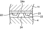
【解決手段】歯車装置3は、相手側のケーシング4の内部に固定可能な外筒11および当該外筒11の内周面に配置された内歯ピン15を有する内歯歯車と、クランク軸13と、内歯ピン15と噛み合うことが可能な外歯14aを有し、クランク軸13の回転力を外筒11に伝達する揺動歯車14とを備えている。外筒11は、相手側のケーシング4の内周面に形成された雌スプライン部に連結可能なスプライン部21を外周面に有している。スプライン部21は、外筒11の外周面において当該外筒11の軸方向に延びる複数の突起22を有する。
【選択図】図1
Description
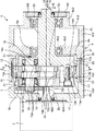
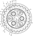
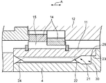
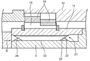
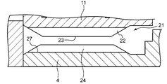
歯車装置3は、ケーシング4の内部に固定された状態で所定の減速比で回転力を伝達することが可能な構成を有する。本実施形態の歯車装置3は、図1〜2に示されるように、外筒11と、キャリア12と、クランク軸13と、揺動歯車14と、複数の内歯ピン15と、スパーギヤ16と、出力軸20とを備えている。
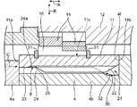
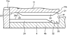
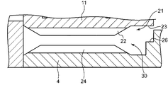
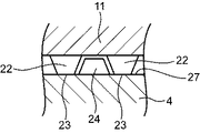
当接面23は、外筒11が固定される相手側のケーシング4の複数の突起24の外側の端面24aに当接する。これにより、外筒11は、その中心軸が当該ケーシング4の中心軸に一致した状態(すなわちこれらの中心軸が回転駆動装置1の中心軸Oに一致した状態)でケーシング4の内部に固定される。このとき、底面25と突起24との間に隙間g(図3参照)が形成される。
2 モータ
3 歯車装置
4 ケーシング
5 軸受
11 外筒
12 キャリア
13 クランク軸(回転軸)
14 揺動歯車(外歯歯車)
14a 外歯
15 内歯ピン(内歯)
20 出力軸
21 スプライン部
22 突起
23 当接面
Claims (7)
- 相手側部材の内部に固定される歯車装置であって、
前記相手側部材の内部に固定可能な外筒および当該外筒の内周面に配置された内歯を有する内歯歯車と、
回転軸と、
前記内歯と噛み合うことが可能な外歯を有し、前記回転軸の回転力を前記外筒に伝達する外歯歯車と
を備え、
前記外筒は、前記相手側部材の内周面に形成された雌スプライン部に連結可能なスプライン部を外周面に有している、
ことを特徴とする歯車装置。 - 前記スプライン部は、前記外筒の外周面のうち前記内歯が配置された位置の裏側になる位置に配置されている、
請求項1に記載の歯車装置。 - 前記外筒は、当該外筒の半径方向外側を向き、かつ、前記相手側部材の対向する面に対して当接する当接面を有する、
請求項1または2に記載の歯車装置。 - 前記当接面は、前記スプライン部から前記外筒の軸方向に離れた位置に配置されている、
請求項3に記載の歯車装置。 - 前記スプライン部は、前記外筒2の外周面の周方向に間隔をおいて配置された複数の突起を有し、
前記当接面は、前記突起の外面によって構成されている、
請求項3に記載の歯車装置。 - 前記回転軸は、偏心部を有するクランク軸であり、
前記外歯歯車は、前記クランク軸の偏心部の回転に連動して揺動する揺動歯車である、
請求項1〜5のいずれかに記載の歯車装置。 - 前記外筒の内部に回転自在に収納されたキャリアと、
前記キャリアに同軸状に設けられ、前記外筒の軸方向に延びる出力軸と
をさらに備えている、
請求項1〜6のいずれかに記載の歯車装置。
Priority Applications (3)
| Application Number | Priority Date | Filing Date | Title |
|---|---|---|---|
| JP2016081119A JP6709666B2 (ja) | 2016-04-14 | 2016-04-14 | 歯車装置 |
| KR1020170043748A KR102362479B1 (ko) | 2016-04-14 | 2017-04-04 | 기어 장치 |
| CN201710225250.9A CN107299964B (zh) | 2016-04-14 | 2017-04-07 | 齿轮装置 |
Applications Claiming Priority (1)
| Application Number | Priority Date | Filing Date | Title |
|---|---|---|---|
| JP2016081119A JP6709666B2 (ja) | 2016-04-14 | 2016-04-14 | 歯車装置 |
Publications (2)
| Publication Number | Publication Date |
|---|---|
| JP2017190837A true JP2017190837A (ja) | 2017-10-19 |
| JP6709666B2 JP6709666B2 (ja) | 2020-06-17 |
Family
ID=60086243
Family Applications (1)
| Application Number | Title | Priority Date | Filing Date |
|---|---|---|---|
| JP2016081119A Active JP6709666B2 (ja) | 2016-04-14 | 2016-04-14 | 歯車装置 |
Country Status (3)
| Country | Link |
|---|---|
| JP (1) | JP6709666B2 (ja) |
| KR (1) | KR102362479B1 (ja) |
| CN (1) | CN107299964B (ja) |
Cited By (2)
| Publication number | Priority date | Publication date | Assignee | Title |
|---|---|---|---|---|
| WO2019064696A1 (ja) | 2017-09-29 | 2019-04-04 | 富士フイルム株式会社 | 平版印刷版原版、平版印刷版の作製方法及び平版印刷方法 |
| WO2023104411A1 (de) * | 2021-12-10 | 2023-06-15 | Zf Friedrichshafen Ag | Passverzahnung zwischen hohlrad und gehäuseteil |
Families Citing this family (1)
| Publication number | Priority date | Publication date | Assignee | Title |
|---|---|---|---|---|
| KR102543898B1 (ko) * | 2022-05-10 | 2023-06-14 | 김은태 | 내치 기어를 플레인 베어링 방식으로 변환시킴으로써 구름 효과가 증대되고 인가 하중이 분산되어 출력 성능과 내구성이 개선된 싸이클로이드 감속기 |
Citations (5)
| Publication number | Priority date | Publication date | Assignee | Title |
|---|---|---|---|---|
| JPS62158160U (ja) * | 1986-03-27 | 1987-10-07 | ||
| JP2007131295A (ja) * | 2005-10-11 | 2007-05-31 | Ntn Corp | 動力出力装置 |
| JP2009057996A (ja) * | 2007-08-30 | 2009-03-19 | Nachi Fujikoshi Corp | 遊星歯車式減速機付油圧モータ |
| JP2011226583A (ja) * | 2010-04-21 | 2011-11-10 | Ntn Corp | 減速装置 |
| JP2013169900A (ja) * | 2012-02-21 | 2013-09-02 | Honda Motor Co Ltd | 車両駆動装置 |
Family Cites Families (15)
| Publication number | Priority date | Publication date | Assignee | Title |
|---|---|---|---|---|
| JPH0784896B2 (ja) * | 1986-11-05 | 1995-09-13 | 株式会社ハーモニック・ドライブ・システムズ | 撓み噛み合い式歯車装置 |
| KR100582446B1 (ko) * | 2004-12-08 | 2006-05-23 | 강종철 | 고효율 하이퍼 사이클로이드 기어 감속기 |
| EP2562441B1 (en) * | 2010-04-21 | 2014-11-19 | NTN Corporation | Decelerating device |
| JP2012067849A (ja) * | 2010-09-24 | 2012-04-05 | Aisin Seiki Co Ltd | 回転駆動装置 |
| JP5490752B2 (ja) * | 2011-06-24 | 2014-05-14 | 住友重機械工業株式会社 | 揺動内接噛合型の減速装置 |
| US9562309B2 (en) * | 2012-05-24 | 2017-02-07 | Changzhou Machine Master Co., Ltd. | Double drive transmission method, mechanism, washing machine and washing method |
| JP5466739B2 (ja) * | 2012-08-24 | 2014-04-09 | ナブテスコ株式会社 | 偏心揺動型歯車装置 |
| JP2014092249A (ja) * | 2012-11-06 | 2014-05-19 | Nabtesco Corp | 歯車装置 |
| US8663049B1 (en) * | 2012-11-28 | 2014-03-04 | Tsun-Tien Yao | Speed reducer |
| JP2015021554A (ja) * | 2013-07-18 | 2015-02-02 | ナブテスコ株式会社 | 偏心揺動型歯車装置 |
| CN103527719B (zh) * | 2013-10-21 | 2016-06-01 | 山东帅克机械制造股份有限公司 | 轴承式rv减速器 |
| CN203743324U (zh) * | 2014-03-25 | 2014-07-30 | 李辛 | 一种纯滚针啮合rv减速机 |
| JP6584054B2 (ja) * | 2014-03-28 | 2019-10-02 | 住友重機械工業株式会社 | 偏心揺動型減速装置 |
| CN105041985A (zh) * | 2015-09-18 | 2015-11-11 | 福建省鲤东精密机械有限公司 | 一种轴承式rv减速机 |
| CN205047748U (zh) * | 2015-10-22 | 2016-02-24 | 广东伊雪松机器人设备有限公司 | Rv减速机 |
-
2016
- 2016-04-14 JP JP2016081119A patent/JP6709666B2/ja active Active
-
2017
- 2017-04-04 KR KR1020170043748A patent/KR102362479B1/ko active Active
- 2017-04-07 CN CN201710225250.9A patent/CN107299964B/zh active Active
Patent Citations (5)
| Publication number | Priority date | Publication date | Assignee | Title |
|---|---|---|---|---|
| JPS62158160U (ja) * | 1986-03-27 | 1987-10-07 | ||
| JP2007131295A (ja) * | 2005-10-11 | 2007-05-31 | Ntn Corp | 動力出力装置 |
| JP2009057996A (ja) * | 2007-08-30 | 2009-03-19 | Nachi Fujikoshi Corp | 遊星歯車式減速機付油圧モータ |
| JP2011226583A (ja) * | 2010-04-21 | 2011-11-10 | Ntn Corp | 減速装置 |
| JP2013169900A (ja) * | 2012-02-21 | 2013-09-02 | Honda Motor Co Ltd | 車両駆動装置 |
Cited By (2)
| Publication number | Priority date | Publication date | Assignee | Title |
|---|---|---|---|---|
| WO2019064696A1 (ja) | 2017-09-29 | 2019-04-04 | 富士フイルム株式会社 | 平版印刷版原版、平版印刷版の作製方法及び平版印刷方法 |
| WO2023104411A1 (de) * | 2021-12-10 | 2023-06-15 | Zf Friedrichshafen Ag | Passverzahnung zwischen hohlrad und gehäuseteil |
Also Published As
| Publication number | Publication date |
|---|---|
| JP6709666B2 (ja) | 2020-06-17 |
| KR20170117876A (ko) | 2017-10-24 |
| CN107299964A (zh) | 2017-10-27 |
| KR102362479B1 (ko) | 2022-02-14 |
| CN107299964B (zh) | 2022-08-30 |
Similar Documents
| Publication | Publication Date | Title |
|---|---|---|
| US8821333B2 (en) | Planetary gear mechanism | |
| CN107606067B (zh) | 齿轮装置 | |
| JP5782321B2 (ja) | 歯車装置 | |
| JP2011212839A (ja) | 偏心揺動型減速機を用いた産業用ロボットの旋回部構造 | |
| JP2017044319A (ja) | 偏心揺動型の歯車装置および産業用ロボット | |
| JP2015021554A (ja) | 偏心揺動型歯車装置 | |
| WO2014073185A1 (ja) | 歯車装置 | |
| JP2023184669A (ja) | 歯車ユニット | |
| JP6709666B2 (ja) | 歯車装置 | |
| TWI763689B (zh) | 齒輪裝置 | |
| CN102782362A (zh) | 齿轮装置 | |
| CN107202100B (zh) | 齿轮装置 | |
| JP5868826B2 (ja) | 減速装置 | |
| TW201400730A (zh) | 偏心搖動型齒輪裝置 | |
| KR102564819B1 (ko) | 기어 장치 및 출력 기어판 | |
| JP2020139535A (ja) | 偏心揺動型の変速機 | |
| JP2020063808A (ja) | 偏心揺動型減速装置 | |
| JP2016080126A (ja) | 偏心揺動型歯車装置 |
Legal Events
| Date | Code | Title | Description |
|---|---|---|---|
| A621 | Written request for application examination |
Free format text: JAPANESE INTERMEDIATE CODE: A621 Effective date: 20190314 |
|
| A977 | Report on retrieval |
Free format text: JAPANESE INTERMEDIATE CODE: A971007 Effective date: 20200109 |
|
| A131 | Notification of reasons for refusal |
Free format text: JAPANESE INTERMEDIATE CODE: A131 Effective date: 20200121 |
|
| A521 | Request for written amendment filed |
Free format text: JAPANESE INTERMEDIATE CODE: A523 Effective date: 20200323 |
|
| TRDD | Decision of grant or rejection written | ||
| A01 | Written decision to grant a patent or to grant a registration (utility model) |
Free format text: JAPANESE INTERMEDIATE CODE: A01 Effective date: 20200519 |
|
| A61 | First payment of annual fees (during grant procedure) |
Free format text: JAPANESE INTERMEDIATE CODE: A61 Effective date: 20200525 |
|
| R150 | Certificate of patent or registration of utility model |
Ref document number: 6709666 Country of ref document: JP Free format text: JAPANESE INTERMEDIATE CODE: R150 |
|
| R250 | Receipt of annual fees |
Free format text: JAPANESE INTERMEDIATE CODE: R250 |
|
| R250 | Receipt of annual fees |
Free format text: JAPANESE INTERMEDIATE CODE: R250 |
|
| R250 | Receipt of annual fees |
Free format text: JAPANESE INTERMEDIATE CODE: R250 |