JP2017190837A - Gear device - Google Patents
Gear device Download PDFInfo
- Publication number
- JP2017190837A JP2017190837A JP2016081119A JP2016081119A JP2017190837A JP 2017190837 A JP2017190837 A JP 2017190837A JP 2016081119 A JP2016081119 A JP 2016081119A JP 2016081119 A JP2016081119 A JP 2016081119A JP 2017190837 A JP2017190837 A JP 2017190837A
- Authority
- JP
- Japan
- Prior art keywords
- outer cylinder
- gear
- casing
- gear device
- peripheral surface
- Prior art date
- Legal status (The legal status is an assumption and is not a legal conclusion. Google has not performed a legal analysis and makes no representation as to the accuracy of the status listed.)
- Granted
Links
Images
Classifications
-
- F—MECHANICAL ENGINEERING; LIGHTING; HEATING; WEAPONS; BLASTING
- F16—ENGINEERING ELEMENTS AND UNITS; GENERAL MEASURES FOR PRODUCING AND MAINTAINING EFFECTIVE FUNCTIONING OF MACHINES OR INSTALLATIONS; THERMAL INSULATION IN GENERAL
- F16H—GEARING
- F16H49/00—Other gearings
- F16H49/001—Wave gearings, e.g. harmonic drive transmissions
-
- F—MECHANICAL ENGINEERING; LIGHTING; HEATING; WEAPONS; BLASTING
- F16—ENGINEERING ELEMENTS AND UNITS; GENERAL MEASURES FOR PRODUCING AND MAINTAINING EFFECTIVE FUNCTIONING OF MACHINES OR INSTALLATIONS; THERMAL INSULATION IN GENERAL
- F16H—GEARING
- F16H1/00—Toothed gearings for conveying rotary motion
- F16H1/28—Toothed gearings for conveying rotary motion with gears having orbital motion
- F16H1/32—Toothed gearings for conveying rotary motion with gears having orbital motion in which the central axis of the gearing lies inside the periphery of an orbital gear
- F16H2001/323—Toothed gearings for conveying rotary motion with gears having orbital motion in which the central axis of the gearing lies inside the periphery of an orbital gear comprising eccentric crankshafts driving or driven by a gearing
-
- F—MECHANICAL ENGINEERING; LIGHTING; HEATING; WEAPONS; BLASTING
- F16—ENGINEERING ELEMENTS AND UNITS; GENERAL MEASURES FOR PRODUCING AND MAINTAINING EFFECTIVE FUNCTIONING OF MACHINES OR INSTALLATIONS; THERMAL INSULATION IN GENERAL
- F16H—GEARING
- F16H1/00—Toothed gearings for conveying rotary motion
- F16H1/28—Toothed gearings for conveying rotary motion with gears having orbital motion
- F16H1/32—Toothed gearings for conveying rotary motion with gears having orbital motion in which the central axis of the gearing lies inside the periphery of an orbital gear
- F16H2001/327—Toothed gearings for conveying rotary motion with gears having orbital motion in which the central axis of the gearing lies inside the periphery of an orbital gear with the orbital gear having internal gear teeth
Landscapes
- Engineering & Computer Science (AREA)
- General Engineering & Computer Science (AREA)
- Mechanical Engineering (AREA)
- Retarders (AREA)
Abstract
Description
本発明は、外筒を有する歯車装置に関するものである。 The present invention relates to a gear device having an outer cylinder.
一対の相手側部材間で所定の減速比で回転力を伝達する偏心揺動型歯車装置としては、特許文献1に記載されるように、内歯歯車と、外歯歯車とを有し、内歯歯車と外歯歯車との相対回転をキャリアとケーシングとの相対回転として取り出すものが知られている。この内歯歯車は、円筒状のケーシングと、当該円筒状ケーシングの内周面に取り付けられた内歯を構成するピンとを有する。内歯歯車のケーシングは、一方の相手側部材に複数のボルトを用いて締結される。
As described in
上記の歯車装置では内歯歯車を構成するケーシングが相手側部材に複数のボルトを用いて締結されるので、当該ケーシングを相手側部材に連結する作業が複雑で手間がかかるので、組立作業性の向上が難しいという問題がある。 In the above gear device, the casing that constitutes the internal gear is fastened to the mating member using a plurality of bolts, and therefore, the work of connecting the casing to the mating member is complicated and laborious. There is a problem that improvement is difficult.
本発明はかかる問題を解決するためになされたものであり、内歯歯車を構成する部材を相手側部材に連結する作業を容易に行うことが可能な歯車装置を提供することにある。 The present invention has been made to solve such a problem, and it is an object of the present invention to provide a gear device capable of easily performing an operation of connecting a member constituting an internal gear to a counterpart member.
前記の目的を達成するため、本発明の歯車装置は、相手側部材の内部に固定される歯車装置であって、前記相手側部材の内部に固定可能な外筒および当該外筒の内周面に配置された内歯を有する内歯歯車と、回転軸と、前記内歯と噛み合うことが可能な外歯を有し、前記回転軸の回転力を前記外筒に伝達する外歯歯車とを備え、前記外筒は、前記相手側部材の内周面に形成された雌スプライン部に連結可能なスプライン部を外周面に有していることを特徴とする。 In order to achieve the above object, a gear device of the present invention is a gear device that is fixed inside a mating member, an outer cylinder that can be fixed inside the mating member, and an inner peripheral surface of the outer cylinder. An internal gear having internal teeth disposed on the rotating shaft, and an external gear having external teeth capable of meshing with the internal teeth and transmitting the rotational force of the rotational shaft to the external cylinder. The outer cylinder has a spline portion on the outer peripheral surface that can be connected to a female spline portion formed on the inner peripheral surface of the counterpart member.
かかる構成では、内歯歯車を構成する外筒は、その外周面にスプライン部を有している。そのため、外筒を相手側部材の内部に固定するときに、外筒をその軸方向に沿って相手側部材の内部に挿入することにより、外筒のスプライン部が相手側部材の内周面に形成された雌スプライン部にスプライン結合されるので、外筒を相手側部材に容易に連結することが可能である。その結果、歯車装置を備えた装置の組立作業性を向上させることが可能である。 In such a configuration, the outer cylinder constituting the internal gear has a spline portion on the outer peripheral surface thereof. Therefore, when the outer cylinder is fixed inside the mating member, the outer cylinder is inserted into the mating member along the axial direction so that the spline portion of the outer cylinder is placed on the inner peripheral surface of the mating member. Since it is spline-coupled to the formed female spline portion, the outer cylinder can be easily connected to the mating member. As a result, it is possible to improve the assembly workability of the device provided with the gear device.
前記スプライン部は、前記外筒の外周面のうち前記内歯が配置された位置の裏側になる位置に配置されているのが好ましい。 It is preferable that the spline portion is disposed at a position on the back side of the position where the inner teeth are disposed on the outer peripheral surface of the outer cylinder.
かかる構成では、スプライン部は、外筒の外周面において内歯の裏側において相手側部材に連結される。そのため、外筒が内歯を介して外歯歯車から伝達された回転負荷(トルク)を受けても、その回転負荷を外筒とともにスプライン部を介して結合された相手側部材によって受けることが可能になる。これにより、外筒が変形するおそれが低減する。 In such a configuration, the spline portion is connected to the counterpart member on the back side of the inner teeth on the outer peripheral surface of the outer cylinder. Therefore, even if the outer cylinder receives a rotational load (torque) transmitted from the external gear via the internal teeth, the rotational load can be received by the mating member coupled with the outer cylinder via the spline portion. become. Thereby, the possibility that the outer cylinder is deformed is reduced.
前記外筒は、当該外筒の半径方向外側を向き、かつ、前記相手側部材の対向する面に対して当接する当接面を有するのが好ましい。 It is preferable that the outer cylinder has a contact surface that faces the outer side in the radial direction of the outer cylinder and contacts the opposing surface of the counterpart member.
かかる構成では、外筒の当接面を相手側部材の対向する面に対して当接する、いわゆるインロー結合によって、外筒の中心軸と相手側部材の中心軸とを互いに容易にかつ正確に位置合わせすることが可能である。 In this configuration, the center axis of the outer cylinder and the center axis of the counterpart member are easily and accurately positioned by so-called inlay coupling in which the contact surface of the outer cylinder abuts against the opposing surface of the counterpart member. Can be combined.
前記当接面は、前記スプライン部から前記外筒の軸方向に離れた位置に配置されているのが好ましい。 The contact surface is preferably disposed at a position away from the spline portion in the axial direction of the outer cylinder.
かかる構成では、スプライン部は当接面から離れた位置で相手側部材の雌スプライン部と容易にスプライン結合することが可能である。 In such a configuration, the spline portion can be easily splined with the female spline portion of the counterpart member at a position away from the contact surface.
前記スプライン部は、前記外筒2の外周面の周方向に間隔をおいて配置された複数の突起を有し、前記当接面は、前記突起の外面によって構成されているのが好ましい。
It is preferable that the spline part has a plurality of protrusions arranged at intervals in the circumferential direction of the outer peripheral surface of the
かかる構成では、当接面がスプライン部の突起の外面に形成されているので、当該当接面を容易に加工可能である。 In such a configuration, since the contact surface is formed on the outer surface of the projection of the spline portion, the contact surface can be easily processed.
前記回転軸は、偏心部を有するクランク軸であり、前記外歯歯車は、前記クランク軸の偏心部の回転に連動して揺動する揺動歯車であるのが好ましい。 Preferably, the rotation shaft is a crankshaft having an eccentric portion, and the external gear is a swing gear that swings in conjunction with rotation of the eccentric portion of the crankshaft.
かかる構成では、歯車装置は偏心揺動型歯車装置を構成し、一対の相手側部材間で大きな減速比で回転力を伝達することが可能になる。 In such a configuration, the gear device constitutes an eccentric oscillating gear device, and it is possible to transmit the rotational force between the pair of counterpart members with a large reduction ratio.
前記外筒の内部に回転自在に収納されたキャリアと、前記キャリアに同軸状に設けられ、前記外筒の前記軸方向に延びる出力軸とをさらに備えているのが好ましい。 It is preferable that the apparatus further includes a carrier rotatably accommodated in the outer cylinder, and an output shaft provided coaxially with the carrier and extending in the axial direction of the outer cylinder.
かかる構成では、軸受を備えた相手側部材に歯車装置を取り付ける場合には、キャリアに同軸状に設けられた出力軸を相手側部材の軸受に挿入して、キャリアを相手側部材の中心軸に合わせ、それとともに、歯車装置の外筒をケーシングの内部にスプライン結合する。これにより、一作業だけで外筒とキャリアとをそれぞれ相手側部材の中心軸に合わせることができ、歯車装置の組み付けを容易に行うことが可能である。 In such a configuration, when the gear device is attached to the mating member provided with the bearing, the output shaft provided coaxially with the carrier is inserted into the bearing of the mating member, and the carrier is used as the central axis of the mating member. At the same time, the outer cylinder of the gear device is splined to the inside of the casing. As a result, the outer cylinder and the carrier can be aligned with the central axis of the counterpart member with only one operation, and the gear device can be easily assembled.
以上説明したように、本発明の歯車装置によれば、内歯歯車を構成する外筒を相手側部材に連結する作業を容易に行うことができる。 As described above, according to the gear device of the present invention, it is possible to easily perform the operation of connecting the outer cylinder constituting the internal gear to the counterpart member.
以下、本発明を実施するための形態について図面を参照しながら詳細に説明する。 Hereinafter, embodiments for carrying out the present invention will be described in detail with reference to the drawings.
本実施形態に係る歯車装置は、偏心揺動型歯車装置であり、例えば、ロボットの旋回胴や腕関節等の旋回部、または各種工作機械の旋回部に減速機などの種々の用途に適用される歯車装置である。 The gear device according to the present embodiment is an eccentric oscillating gear device, and is applied to various uses such as a reduction gear in a swivel unit such as a swivel trunk or arm joint of a robot or a swivel unit of various machine tools. This is a gear device.
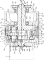
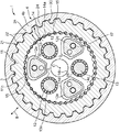
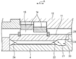
図1〜2には、本実施形態に係わる歯車装置3を内蔵した回転駆動装置1が示されている。この回転駆動装置1は、歯車装置3が相手側部材であるケーシング4の内部に固定された状態でモータ2で発生した回転力を所定の減速比で伝達し、減速された回転力を出力軸20から出力するものである。
1 and 2 show a
具体的には、図1に示される回転駆動装置1は、モータ2と、出力軸20を有する歯車装置3と、歯車装置3を収納するケーシング4と、出力軸20を回転自在に支持する2個の軸受5A、5Bとを有する。
Specifically, the
モータ2は、駆動軸2aを有する。駆動軸2aの先端には、複数の外歯を有するギヤ部2bが形成されている。
The
ケーシング4は、歯車装置3が固定される相手側部材である。ケーシング4は、筒状の3つの部分、すなわち、第1部分4a、第2部分4b、第3部分4cを有し、これらの部分は、回転駆動装置1の中心軸Oに沿って、当該回転駆動装置1の軸方向Aに並んで互いに連結されている。
The
第1部分4aは、モータ2の胴部に固定されている。第1部分4aは、モータ2の駆動軸2aを貫通させる貫通孔4a2が形成された底部4a1と、底部4a1から軸方向Aに延びる筒状部4a3とを有する。
The
第2部分4bは、第2部分4bは、第1部分4aの筒状部4a3の端部に固定されている。第2部分4bは、筒状に形成された胴部4b1と、胴部4b1の端部から内側に延びるように形成された板状部4b2とを有する。板状部4b2の中心に貫通孔4b3が形成されている。貫通孔4b3には、軸受5Aが配置されている。
As for the
第1部分4aと第2部分4bとによって、歯車装置3を収納する空間部4eが形成されている。
A
第3部分4cは、第2部分4bに固定されている。第3部分4cは、第2部分4bの胴部4b1から軸方向Aに延びる環状部4c1と、環状部4c1から径方向内側に延びる径方向部4c2と、径方向部4c2の内端部から軸方向Aに延びる軸方向部4c3とを有する。軸方向部4c3は、筒状に形成され、軸受5Bが取り付けられている。軸方向部4c3の端部開口は、歯車装置3の出力軸20が外部に突出した状態で蓋板4dによって閉じられている。
The
2個の軸受5A、5Bは、ケーシング4の第2部分4bおよび第3部分4cにそれぞれ固定されている。2個の軸受5A、5Bは、歯車装置3の出力軸20を回転自在に支持する。
The two
出力軸20の先端には、ケーシング4の外部にある他の相手側部材(図示せず)が連結される。出力軸20の回転力は、当該他の相手側部材に伝達される
歯車装置3は、ケーシング4の内部に固定された状態で所定の減速比で回転力を伝達することが可能な構成を有する。本実施形態の歯車装置3は、図1〜2に示されるように、外筒11と、キャリア12と、クランク軸13と、揺動歯車14と、複数の内歯ピン15と、スパーギヤ16と、出力軸20とを備えている。
The other end member (not shown) outside the
外筒11は、略円筒状の部材であり、歯車装置3の外面を構成するケースとして機能する。外筒11の内周面には、軸方向Aに延びる複数のピン溝11c(図2〜3参照)が当該外筒11の内周面に沿って等間隔に形成されている。各ピン溝11cには、それぞれ内歯ピン15の一部が嵌合している。内歯ピン15は、円柱状の細いピンであり、外歯歯車からなる揺動歯車14が噛み合う内歯として機能する。内歯ピン15の軸方向Aの移動は、外筒11の内周面の溝に嵌合する止め輪31によって規制される。
The
ケーシング4の内部に固定可能な外筒11、および当該外筒11の内周面に配置された内歯ピン15によって、内歯歯車が構成される。
An internal gear is constituted by the
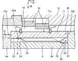
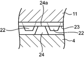
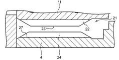
図2〜5に示されるように、外筒11は、その外周面において、ケーシング4の内周面に形成された雌スプライン部32にスプライン結合するためのスプライン部21を有している。スプライン部21は、外筒11の外周面のうち内歯ピン15が配置された位置の裏側になる位置に配置されている。
2-5, the
スプライン部21は、軸方向Aに延びる複数の突起22を有する。複数の突起22は、外筒2の外周面の周方向に間隔をおいて配置されている。複数の突起22は、外筒11の半径方向Bを向いて当該外筒11の外側へ放射状に突出するように等間隔に配置されている。
The
このスプライン部21の複数の突起22が相手側のケーシング4の第2部分4bの内周面に形成された雌スプライン部32の複数の突起24の間に形成された凹部33に挿入されることにより、スプライン結合部30が構成される。よって、スプライン結合部30は、外筒11の軸方向Aの移動は許容した状態で、当該外筒11をケーシング4に対して相対回転できないように当該ケーシング4に固定する。
The plurality of
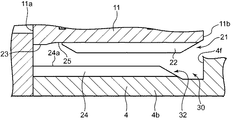
また、外筒11は、その外周面において、ケーシング4に当接して当該ケーシング4の中心軸と外筒11の中心軸を合わせるための当接面23を有する。図3〜4に示される当接面23は、スプライン部21の突起22から軸方向Aに離れた位置に配置されているが、本発明はこれに限定されない。
Further, the
当接面23は、外筒11の半径方向Bの外側を向く面であって、外筒11の周方向全体に形成されている。当接面23は、外筒11の中心軸と同心の環状の面で構成される。当接面23は、突起22、22間の底面25よりも若干外側に盛り上がっている。
当接面23は、外筒11が固定される相手側のケーシング4の複数の突起24の外側の端面24aに当接する。これにより、外筒11は、その中心軸が当該ケーシング4の中心軸に一致した状態(すなわちこれらの中心軸が回転駆動装置1の中心軸Oに一致した状態)でケーシング4の内部に固定される。このとき、底面25と突起24との間に隙間g(図3参照)が形成される。
The abutting
The
なお、この回転駆動装置1の構成では、ケーシング4側の突起24は、外側の端面24aが当接面23に当接できるように、外筒11側の突起12よりも軸方向Aに長くなるように形成されている。
In this configuration of the
本実施形態では、上記の当接面23と軸受5Aとの両方によって歯車装置3の芯出しがなされる。
In the present embodiment, the
本実施形態では、外筒11における軸方向Aを向く両側の端面11a、11bは、それぞれケーシング4の第1部分4aの端面および第2部分4bの段部4fに当接する。したがって、ケーシング4のこれら第1部分4aおよび第2部分4bによって外筒11が挟まれることにより、外筒11の軸方向Aの移動が規制される。
In this embodiment, the end surfaces 11a and 11b on both sides of the
キャリア12は、図1に示されるように、外筒11と同軸上に配置された状態でその外筒11内に収容されている。キャリア12は、外筒11に対して同じ軸回りに相対回転することが可能である。このキャリア12には、出力軸20が同軸状に設けられる。本実施形態の出力軸20はキャリア12の基部12aに一体形成されている。なお、本発明の歯車装置は出力軸20がキャリア12に一体形成されること限定されるものではなく、別部材の出力軸20をキャリア12に同軸状にボルト締めなどによって固定してもよい。
As shown in FIG. 1, the
本実施形態のキャリア12は、基部12aと、端板部12bとを備えている。基部12aと端板部12bとの間には、外筒11とキャリア12との間における回転力の伝達をする揺動歯車14を収納する収容空間12cが形成されている。収容空間12cは、キャリア12の外部に通じる貫通孔12dと連通している。
The
基部12aは、端板部12bに向かって軸方向Aに延びるシャフト部12eを有する。シャフト部12eは、ボルト17によって端板部12bに締結されている。基部12aおよび端板部12bは、鋳鉄などによって製造されている。
The
クランク軸13は、キャリア12に回転自在に支持された回転軸である。クランク軸13は、中心軸Oの周囲に等間隔に複数個配置されている。各クランク軸13には、スパーギヤ16がそれぞれ取り付けられている。各スパーギヤ16は、モータ2の駆動軸2a先端のギヤ部2bとそれぞれ噛み合っている。これにより、各スパーギヤ16は、モータ2の回転駆動力をクランク軸13に伝達することが可能である。各クランク軸13は、一対のクランク軸受18を介してキャリア12に回転自在に支持されている。
The
クランク軸13は、複数(本実施形態では2つ)の偏心部13aを有している。この複数の偏心部13aは、一対のクランク軸受18の間の位置で軸方向に並ぶように配置されている。各偏心部13aは、それぞれクランク軸13の軸心から所定の偏心量で偏心した円柱状に形成されている。そして、各偏心部13aは、互いに所定角度の位相差を有するようにクランク軸13に形成されている。
The
揺動歯車14は、内歯ピン15と噛み合うことが可能な外歯14aを有し、クランク軸13の回転力を外筒11に伝達する外歯歯車である。揺動歯車14は、クランク軸13の偏心部13aの回転に連動して揺動するようにキャリア12に支持されている。本実施形態では、2枚の揺動歯車14がキャリア12に設けられている。2個の揺動歯車14は、クランク軸13の各偏心部13aにそれぞれころ軸受19を介して取り付けられている。揺動歯車14は、外筒11の内径よりも少し小さく形成されており、クランク軸13が回転するときに偏心部13aの偏心回転に連動して外筒11内面の内歯ピン15に噛み合いながら揺動回転する。
The
それぞれの揺動歯車14は、図1〜2に示されるように、内歯ピン15と噛み合うことが可能な外歯14aと、中央部貫通孔14bと、複数の偏心部挿通孔14cと、複数のシャフト部挿通孔14dとを有する。揺動歯車14の歯数(外歯14aの数)は、内歯ピン15の数よりも若干少なくなっている。
As shown in FIGS. 1 and 2, each
偏心部挿通孔14cは、揺動歯車14において中央部貫通孔14bの周囲に周方向に等間隔で設けられている。各偏心部挿通孔14cには、ころ軸受19を介装した状態で各クランク軸13の偏心部13aがそれぞれ挿通されている。
The eccentric
シャフト部挿通孔14dは、揺動歯車14において中央部貫通孔14bの周囲に周方向に等間隔で設けられている。各シャフト部挿通孔14dは、周方向において偏心部挿通孔14c間の位置にそれぞれ配設されている。各シャフト部挿通孔14dには、キャリア12の各シャフト部12eが遊びを有した状態で挿通されている。
The shaft
図1〜2に示される歯車装置3を備えた回転駆動装置1は、以下のような動作をする。まず、クランク軸13に連結されたスパーギヤ16が、モータ2の駆動軸2aの先端のギヤ部2bからの回転駆動力を受けると、各クランク軸13は、軸回りに回転する。このとき、各クランク軸13の回転に伴って、そのクランク軸13の偏心部13aが偏心回転する。これにより、揺動歯車14は、偏心部13aの偏心回転に連動して外筒11の内面の内歯ピン15に噛み合いながら揺動回転する。揺動歯車14の揺動回転は、各クランク軸13を通じてキャリア12に伝達される。本実施形態では、外筒11はケーシング4にスプライン結合されて回転できないように固定されているので、キャリア12および当該キャリア12に一体形成された出力軸20は、入力された回転から減速された回転数で外筒11及びケーシング4に対して相対回転することが可能である。出力軸20は、回転駆動装置1の外部の部材へ回転力を伝達する。
The
上記のように構成された本実施形態の歯車装置3では、内歯歯車を構成する外筒11は、その外周面に当該外筒11の軸方向に延びる複数の突起を有するスプライン部21を有している。そのため、外筒11をケーシング4の内部に固定するときに、外筒11をその軸方向Aに沿ってケーシング4の内部に挿入することにより、外筒11のスプライン部21がケーシング4の内周面に形成された雌スプライン部32にスプライン結合することにより容易に連結することが可能である。その結果、歯車装置3を備えた装置の組立作業性を向上させることが可能である。
In the
また、本実施形態では、外筒11とケーシング4とがスプライン結合されるとともにケーシング4の第1部分4aおよび第2部分4bによって外筒11が挟まれることにより、外筒11の軸方向Aの移動が規制されるので、外筒11を固定する作業の工数を低減することも可能になる。
In the present embodiment, the
本実施形態の歯車装置3では、スプライン部21は、外筒11の外周面のうち内歯ピン15が配置された位置の裏側になる位置に配置されている。この構成では、スプライン部21は、外筒11の外周面において内歯ピン15の裏側においてケーシング4に連結される。そのため、外筒11が内歯ピン15を介して揺動歯車14から伝達された回転負荷(トルク)を受けても、その回転負荷を外筒11とともにスプライン部21を介して結合されたケーシング4によって受けることが可能になる。これにより、外筒11が変形するおそれが低減する。
In the
本実施形態の歯車装置3では、外筒11は、当該外筒11の半径方向Bの外側を向き、かつ、ケーシング4の対向する面(すなわち、突起24の外側の端面24a)に対して当接する当接面23を有している。これにより、外筒11の当接面23をケーシング4の対向する面に対して当接する、いわゆるインロー結合によって、外筒11の中心軸とケーシング4の中心軸とを互いに容易にかつ正確に位置合わせすることが可能である。その結果、上記のように、外筒11をケーシング4の内部にスプライン結合した構造であっても、外筒11とケーシング4との中心軸を正確に合わせることが可能になる。
In the
とくに、上記実施形態の歯車装置3のように、外筒4が固定側である構成、言い換えれば、外筒4が静止したケーシング4に固定されている構成では、外筒11の当接面23がケーシング4の突起24の外側の端面24aに当接することによって、外筒が回転する歯車装置の構成と比較して、外筒11とケーシング4との中心軸を高い精度で合わせることを容易に行うことが可能である。
In particular, in the configuration in which the
上記実施形態の歯車装置3では、当接面23は、スプライン部21から外筒11の軸方向Aに離れた位置に配置されている。そのため、スプライン部21は当接面23から離れた位置で相手側のケーシング4の雌スプライン部32と容易にスプライン結合することが可能である。
In the
上記実施形態の歯車装置3は、回転軸としての偏心部13aを有するクランク軸13と、内歯歯車としてクランク軸13の偏心部13aの回転に連動して揺動する揺動歯車14とを備えている。これにより、歯車装置3は偏心揺動型歯車装置3を構成し、一対のケーシング4間で大きな減速比で回転力を伝達することが可能になる。しかも、揺動歯車14が揺動回転しても、外筒11の半径方向Bの外側を向く当接面23がケーシング4に当接した状態で外筒11がケーシング4に結合(いわゆるインロー結合)しているので、外筒11がケーシング4の中心軸からのずれを回避する(抑える)ことが可能である。
The
上記実施形態の歯車装置3では、出力軸20は、キャリア12に同軸状に設けられ、外筒11の軸方向Aに延びる。したがって、軸受5A、5Bが固定されたケーシング4に歯車装置3を取り付ける場合には、キャリア12に同軸状に設けられた出力軸20をケーシング4側の軸受5A、5Bに挿入して、キャリア12をケーシング4の中心軸に合わせ、それとともに、歯車装置3の外筒11をケーシングの内部にスプライン結合する。これにより、一作業だけで外筒11とキャリア12とをそれぞれケーシング4の中心軸に合わせることができ、歯車装置3の組み付けを容易に行うことが可能である。
In the
また、歯車装置3を備えた回転駆動装置1の構成において、歯車装置3の外筒11が連結されたケーシング4に軸受5A、5Bが固定されているので、歯車装置3が軸受を有していなくても、ケーシング4側の軸受5A、5Bが、キャリア12に一体に形成された出力軸20を回転自在に支持することにより、ケーシング4を基準として、歯車装置3の外筒11とキャリア12の中心軸を容易にかつ正確に合わせることが可能である。
Further, in the configuration of the
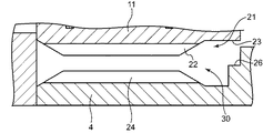
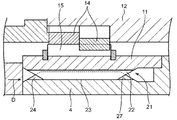
なお、上記実施形態の図3〜5に示される外筒11の当接面23は、相手側のケーシング4の突起24の外側の端面24aに当接するが、本発明はこれに限定されない。当接面23は、外筒11の半径方向Bの外側を向き、かつ、相手側部材の対向する面に対して当接する面であればよい。したがって、本発明の他の実施形態として、図6〜7に示されるように、当接面23が相手側のケーシング4の突起24から軸方向Aに離れた位置に設けられた対向面26に当接するようにしてよい。この図6〜7に示される構成においても、外筒11の当接面23をケーシング4の対向面26に対して当接する、いわゆるインロー結合によって、外筒11とケーシング4との中心軸を容易にかつ正確に合わせることが可能である。図6〜7の変形例でも、当接面23は、スプライン部21からも外筒11の軸方向に離れた位置に配置されているので、スプライン部21は当接面23から離れた位置で相手側のケーシング4の雌スプライン部32と容易にスプライン結合することが可能である。
In addition, although the
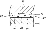
さらに、本発明のさらに他の実施形態として、図8〜10に示されるように、スプライン部21の突起22の外面が当接面23として構成されていてもよい。この構成では、突起22の先端に形成された当接面23は、ケーシング4の突起24の間の歯底を形成する歯底面27に当接する。この構成では、当接面23がスプライン部21の突起22の先端に形成されているので、当該当接面23を容易に加工可能である。なお、この図8〜10に示される構成の歯車装置では、外筒11はケーシング4内部に焼きばめなどによって圧入すればよい。この図8〜10に示される構成においても、外筒11の当接面23をケーシング4の歯底面27に対して当接する、いわゆるインロー結合によって、外筒11とケーシング4との中心軸を容易にかつ正確に合わせることが可能である。
Furthermore, as still another embodiment of the present invention, as shown in FIGS. 8 to 10, the outer surface of the
上記実施形態では、本発明の歯車装置3として偏心揺動型歯車装置3、すなわち、回転軸がクランク軸13であり、内歯歯車がクランク軸13の回転に連動して揺動する揺動歯車14である歯車装置3を例に挙げて説明しているが、本発明はこれに限定されるものではない。本発明では、内歯歯車、回転軸および外歯歯車を備えた歯車装置であれば種々の形態の歯車装置でもよい。例えば、本発明の歯車装置は、遊星歯車装置、すなわち、外歯歯車として遊星歯車を備え、かつ、回転軸に連結された太陽歯車に噛み合う構成の歯車装置であってもよい。
In the above embodiment, the eccentric
1 回転駆動装置
2 モータ
3 歯車装置
4 ケーシング
5 軸受
11 外筒
12 キャリア
13 クランク軸(回転軸)
14 揺動歯車(外歯歯車)
14a 外歯
15 内歯ピン(内歯)
20 出力軸
21 スプライン部
22 突起
23 当接面
DESCRIPTION OF
14 Oscillating gear (external gear)
14a
20
Claims (7)
前記相手側部材の内部に固定可能な外筒および当該外筒の内周面に配置された内歯を有する内歯歯車と、
回転軸と、
前記内歯と噛み合うことが可能な外歯を有し、前記回転軸の回転力を前記外筒に伝達する外歯歯車と
を備え、
前記外筒は、前記相手側部材の内周面に形成された雌スプライン部に連結可能なスプライン部を外周面に有している、
ことを特徴とする歯車装置。 A gear device fixed inside the mating member,
An external gear that can be fixed inside the counterpart member and an internal gear that has internal teeth that are arranged on the inner peripheral surface of the external tube;
A rotation axis;
An external gear that has external teeth that can mesh with the internal teeth, and that transmits the rotational force of the rotary shaft to the external cylinder;
The outer cylinder has a spline portion on the outer peripheral surface that can be connected to a female spline portion formed on the inner peripheral surface of the counterpart member.
A gear device characterized by that.
請求項1に記載の歯車装置。 The spline part is disposed at a position on the back side of the position where the inner teeth are disposed on the outer peripheral surface of the outer cylinder.
The gear device according to claim 1.
請求項1または2に記載の歯車装置。 The outer cylinder has an abutting surface that faces the outer side of the outer cylinder in the radial direction and that abuts against an opposing surface of the counterpart member.
The gear device according to claim 1 or 2.
請求項3に記載の歯車装置。 The contact surface is disposed at a position away from the spline portion in the axial direction of the outer cylinder,
The gear device according to claim 3.
前記当接面は、前記突起の外面によって構成されている、
請求項3に記載の歯車装置。 The spline part has a plurality of protrusions arranged at intervals in the circumferential direction of the outer peripheral surface of the outer cylinder 2;
The contact surface is constituted by an outer surface of the protrusion.
The gear device according to claim 3.
前記外歯歯車は、前記クランク軸の偏心部の回転に連動して揺動する揺動歯車である、
請求項1〜5のいずれかに記載の歯車装置。 The rotating shaft is a crankshaft having an eccentric portion;
The external gear is a rocking gear that rocks in conjunction with the rotation of the eccentric portion of the crankshaft.
The gear apparatus in any one of Claims 1-5.
前記キャリアに同軸状に設けられ、前記外筒の軸方向に延びる出力軸と
をさらに備えている、
請求項1〜6のいずれかに記載の歯車装置。 A carrier housed rotatably in the outer cylinder;
An output shaft provided coaxially on the carrier and extending in the axial direction of the outer cylinder;
The gear apparatus in any one of Claims 1-6.
Priority Applications (3)
| Application Number | Priority Date | Filing Date | Title |
|---|---|---|---|
| JP2016081119A JP6709666B2 (en) | 2016-04-14 | 2016-04-14 | Gear device |
| KR1020170043748A KR102362479B1 (en) | 2016-04-14 | 2017-04-04 | Gear apparatus |
| CN201710225250.9A CN107299964B (en) | 2016-04-14 | 2017-04-07 | Gear device |
Applications Claiming Priority (1)
| Application Number | Priority Date | Filing Date | Title |
|---|---|---|---|
| JP2016081119A JP6709666B2 (en) | 2016-04-14 | 2016-04-14 | Gear device |
Publications (2)
| Publication Number | Publication Date |
|---|---|
| JP2017190837A true JP2017190837A (en) | 2017-10-19 |
| JP6709666B2 JP6709666B2 (en) | 2020-06-17 |
Family
ID=60086243
Family Applications (1)
| Application Number | Title | Priority Date | Filing Date |
|---|---|---|---|
| JP2016081119A Active JP6709666B2 (en) | 2016-04-14 | 2016-04-14 | Gear device |
Country Status (3)
| Country | Link |
|---|---|
| JP (1) | JP6709666B2 (en) |
| KR (1) | KR102362479B1 (en) |
| CN (1) | CN107299964B (en) |
Cited By (2)
| Publication number | Priority date | Publication date | Assignee | Title |
|---|---|---|---|---|
| WO2019064696A1 (en) | 2017-09-29 | 2019-04-04 | 富士フイルム株式会社 | Planographic printing plate original plate, method for manufacturing planographic printing plate, and planographic printing method |
| WO2023104411A1 (en) * | 2021-12-10 | 2023-06-15 | Zf Friedrichshafen Ag | Spline toothing between ring gear and housing part |
Families Citing this family (1)
| Publication number | Priority date | Publication date | Assignee | Title |
|---|---|---|---|---|
| KR102543898B1 (en) * | 2022-05-10 | 2023-06-14 | 김은태 | Cycloid reducer with improved durability and performance by increasing rolling effect and distributing applied load by converting internal gear into plain bearing |
Citations (5)
| Publication number | Priority date | Publication date | Assignee | Title |
|---|---|---|---|---|
| JPS62158160U (en) * | 1986-03-27 | 1987-10-07 | ||
| JP2007131295A (en) * | 2005-10-11 | 2007-05-31 | Ntn Corp | Power output device |
| JP2009057996A (en) * | 2007-08-30 | 2009-03-19 | Nachi Fujikoshi Corp | Planetary gear type hydraulic motor with reduction gear |
| JP2011226583A (en) * | 2010-04-21 | 2011-11-10 | Ntn Corp | Decelerating device |
| JP2013169900A (en) * | 2012-02-21 | 2013-09-02 | Honda Motor Co Ltd | Vehicle-driving system |
Family Cites Families (15)
| Publication number | Priority date | Publication date | Assignee | Title |
|---|---|---|---|---|
| JPH0784896B2 (en) * | 1986-11-05 | 1995-09-13 | 株式会社ハーモニック・ドライブ・システムズ | Flexible mesh type gear device |
| KR100582446B1 (en) * | 2004-12-08 | 2006-05-23 | 강종철 | High Efficiency Hyper Cycloidal Gear Reducer |
| EP2562441B1 (en) * | 2010-04-21 | 2014-11-19 | NTN Corporation | Decelerating device |
| JP2012067849A (en) * | 2010-09-24 | 2012-04-05 | Aisin Seiki Co Ltd | Rotary driving device |
| JP5490752B2 (en) * | 2011-06-24 | 2014-05-14 | 住友重機械工業株式会社 | Swing intermeshing type speed reducer |
| US9562309B2 (en) * | 2012-05-24 | 2017-02-07 | Changzhou Machine Master Co., Ltd. | Double drive transmission method, mechanism, washing machine and washing method |
| JP5466739B2 (en) * | 2012-08-24 | 2014-04-09 | ナブテスコ株式会社 | Eccentric oscillating gear unit |
| JP2014092249A (en) * | 2012-11-06 | 2014-05-19 | Nabtesco Corp | Gear device |
| US8663049B1 (en) * | 2012-11-28 | 2014-03-04 | Tsun-Tien Yao | Speed reducer |
| JP2015021554A (en) * | 2013-07-18 | 2015-02-02 | ナブテスコ株式会社 | Eccentric oscillation type gear device |
| CN103527719B (en) * | 2013-10-21 | 2016-06-01 | 山东帅克机械制造股份有限公司 | Bearing-type RV speed reduction unit |
| CN203743324U (en) * | 2014-03-25 | 2014-07-30 | 李辛 | Pure-roller needle meshing RV speed reducer |
| JP6584054B2 (en) * | 2014-03-28 | 2019-10-02 | 住友重機械工業株式会社 | Eccentric rocking speed reducer |
| CN105041985A (en) * | 2015-09-18 | 2015-11-11 | 福建省鲤东精密机械有限公司 | Bearing type RV speed reducer |
| CN205047748U (en) * | 2015-10-22 | 2016-02-24 | 广东伊雪松机器人设备有限公司 | Rv speed reducer |
-
2016
- 2016-04-14 JP JP2016081119A patent/JP6709666B2/en active Active
-
2017
- 2017-04-04 KR KR1020170043748A patent/KR102362479B1/en active Active
- 2017-04-07 CN CN201710225250.9A patent/CN107299964B/en active Active
Patent Citations (5)
| Publication number | Priority date | Publication date | Assignee | Title |
|---|---|---|---|---|
| JPS62158160U (en) * | 1986-03-27 | 1987-10-07 | ||
| JP2007131295A (en) * | 2005-10-11 | 2007-05-31 | Ntn Corp | Power output device |
| JP2009057996A (en) * | 2007-08-30 | 2009-03-19 | Nachi Fujikoshi Corp | Planetary gear type hydraulic motor with reduction gear |
| JP2011226583A (en) * | 2010-04-21 | 2011-11-10 | Ntn Corp | Decelerating device |
| JP2013169900A (en) * | 2012-02-21 | 2013-09-02 | Honda Motor Co Ltd | Vehicle-driving system |
Cited By (2)
| Publication number | Priority date | Publication date | Assignee | Title |
|---|---|---|---|---|
| WO2019064696A1 (en) | 2017-09-29 | 2019-04-04 | 富士フイルム株式会社 | Planographic printing plate original plate, method for manufacturing planographic printing plate, and planographic printing method |
| WO2023104411A1 (en) * | 2021-12-10 | 2023-06-15 | Zf Friedrichshafen Ag | Spline toothing between ring gear and housing part |
Also Published As
| Publication number | Publication date |
|---|---|
| JP6709666B2 (en) | 2020-06-17 |
| KR20170117876A (en) | 2017-10-24 |
| CN107299964A (en) | 2017-10-27 |
| KR102362479B1 (en) | 2022-02-14 |
| CN107299964B (en) | 2022-08-30 |
Similar Documents
| Publication | Publication Date | Title |
|---|---|---|
| US8821333B2 (en) | Planetary gear mechanism | |
| CN107606067B (en) | Gear device | |
| JP5782321B2 (en) | Gear device | |
| JP2011212839A (en) | Structure of turning part of industrial robot using eccentric oscillation type reduction gear | |
| JP2017044319A (en) | Eccentric oscillation type gear device and industrial robot | |
| JP2015021554A (en) | Eccentric oscillation type gear device | |
| WO2014073185A1 (en) | Gear device | |
| JP2023184669A (en) | gear unit | |
| JP6709666B2 (en) | Gear device | |
| TWI763689B (en) | gear unit | |
| CN102782362A (en) | Gear device | |
| CN107202100B (en) | gear unit | |
| JP5868826B2 (en) | Reduction gear | |
| TW201400730A (en) | Eccentric oscillation-type gear device | |
| KR102564819B1 (en) | Gear device and output gear plate | |
| JP2020139535A (en) | Eccentric swing type transmission | |
| JP2020063808A (en) | Eccentric oscillation type speed reduction device | |
| JP2016080126A (en) | Eccentric oscillation type gear device |
Legal Events
| Date | Code | Title | Description |
|---|---|---|---|
| A621 | Written request for application examination |
Free format text: JAPANESE INTERMEDIATE CODE: A621 Effective date: 20190314 |
|
| A977 | Report on retrieval |
Free format text: JAPANESE INTERMEDIATE CODE: A971007 Effective date: 20200109 |
|
| A131 | Notification of reasons for refusal |
Free format text: JAPANESE INTERMEDIATE CODE: A131 Effective date: 20200121 |
|
| A521 | Request for written amendment filed |
Free format text: JAPANESE INTERMEDIATE CODE: A523 Effective date: 20200323 |
|
| TRDD | Decision of grant or rejection written | ||
| A01 | Written decision to grant a patent or to grant a registration (utility model) |
Free format text: JAPANESE INTERMEDIATE CODE: A01 Effective date: 20200519 |
|
| A61 | First payment of annual fees (during grant procedure) |
Free format text: JAPANESE INTERMEDIATE CODE: A61 Effective date: 20200525 |
|
| R150 | Certificate of patent or registration of utility model |
Ref document number: 6709666 Country of ref document: JP Free format text: JAPANESE INTERMEDIATE CODE: R150 |
|
| R250 | Receipt of annual fees |
Free format text: JAPANESE INTERMEDIATE CODE: R250 |
|
| R250 | Receipt of annual fees |
Free format text: JAPANESE INTERMEDIATE CODE: R250 |
|
| R250 | Receipt of annual fees |
Free format text: JAPANESE INTERMEDIATE CODE: R250 |