JP2017165265A - Collision detection device for vehicle - Google Patents

Collision detection device for vehicle Download PDF

Info

Publication number
JP2017165265A
JP2017165265A JP2016052421A JP2016052421A JP2017165265A JP 2017165265 A JP2017165265 A JP 2017165265A JP 2016052421 A JP2016052421 A JP 2016052421A JP 2016052421 A JP2016052421 A JP 2016052421A JP 2017165265 A JP2017165265 A JP 2017165265A
Authority
JP
Japan
Prior art keywords
pressure
detection
tube member
tube
vehicle
Prior art date
Legal status (The legal status is an assumption and is not a legal conclusion. Google has not performed a legal analysis and makes no representation as to the accuracy of the status listed.)
Pending
Application number
JP2016052421A
Other languages
Japanese (ja)
Other versions
JP2017165265A5 (en
Inventor
皓太 天野
Kota Amano
皓太 天野
田辺 貴敏
Takatoshi Tanabe
貴敏 田辺
大祐 中根
Daisuke Nakane
大祐 中根
吉田 智一
Tomokazu Yoshida
智一 吉田
Current Assignee (The listed assignees may be inaccurate. Google has not performed a legal analysis and makes no representation or warranty as to the accuracy of the list.)
Denso Corp
Original Assignee
Denso Corp
Priority date (The priority date is an assumption and is not a legal conclusion. Google has not performed a legal analysis and makes no representation as to the accuracy of the date listed.)
Filing date
Publication date
Application filed by Denso Corp filed Critical Denso Corp
Priority to JP2016052421A priority Critical patent/JP2017165265A/en
Priority to PCT/JP2017/005063 priority patent/WO2017159158A1/en
Priority to DE112017001360.7T priority patent/DE112017001360B4/en
Publication of JP2017165265A publication Critical patent/JP2017165265A/en
Publication of JP2017165265A5 publication Critical patent/JP2017165265A5/ja
Pending legal-status Critical Current

Links

Images

Classifications

    • BPERFORMING OPERATIONS; TRANSPORTING
    • B60VEHICLES IN GENERAL
    • B60RVEHICLES, VEHICLE FITTINGS, OR VEHICLE PARTS, NOT OTHERWISE PROVIDED FOR
    • B60R21/00Arrangements or fittings on vehicles for protecting or preventing injuries to occupants or pedestrians in case of accidents or other traffic risks
    • B60R21/01Electrical circuits for triggering passive safety arrangements, e.g. airbags, safety belt tighteners, in case of vehicle accidents or impending vehicle accidents
    • B60R21/013Electrical circuits for triggering passive safety arrangements, e.g. airbags, safety belt tighteners, in case of vehicle accidents or impending vehicle accidents including means for detecting collisions, impending collisions or roll-over
    • B60R21/0136Electrical circuits for triggering passive safety arrangements, e.g. airbags, safety belt tighteners, in case of vehicle accidents or impending vehicle accidents including means for detecting collisions, impending collisions or roll-over responsive to actual contact with an obstacle, e.g. to vehicle deformation, bumper displacement or bumper velocity relative to the vehicle
    • BPERFORMING OPERATIONS; TRANSPORTING
    • B60VEHICLES IN GENERAL
    • B60RVEHICLES, VEHICLE FITTINGS, OR VEHICLE PARTS, NOT OTHERWISE PROVIDED FOR
    • B60R19/00Wheel guards; Radiator guards, e.g. grilles; Obstruction removers; Fittings damping bouncing force in collisions
    • B60R19/02Bumpers, i.e. impact receiving or absorbing members for protecting vehicles or fending off blows from other vehicles or objects
    • B60R19/48Bumpers, i.e. impact receiving or absorbing members for protecting vehicles or fending off blows from other vehicles or objects combined with, or convertible into, other devices or objects, e.g. bumpers combined with road brushes, bumpers convertible into beds
    • B60R19/483Bumpers, i.e. impact receiving or absorbing members for protecting vehicles or fending off blows from other vehicles or objects combined with, or convertible into, other devices or objects, e.g. bumpers combined with road brushes, bumpers convertible into beds with obstacle sensors of electric or electronic type
    • BPERFORMING OPERATIONS; TRANSPORTING
    • B60VEHICLES IN GENERAL
    • B60RVEHICLES, VEHICLE FITTINGS, OR VEHICLE PARTS, NOT OTHERWISE PROVIDED FOR
    • B60R21/00Arrangements or fittings on vehicles for protecting or preventing injuries to occupants or pedestrians in case of accidents or other traffic risks
    • GPHYSICS
    • G01MEASURING; TESTING
    • G01LMEASURING FORCE, STRESS, TORQUE, WORK, MECHANICAL POWER, MECHANICAL EFFICIENCY, OR FLUID PRESSURE
    • G01L5/00Apparatus for, or methods of, measuring force, work, mechanical power, or torque, specially adapted for specific purposes
    • G01L5/0052Apparatus for, or methods of, measuring force, work, mechanical power, or torque, specially adapted for specific purposes measuring forces due to impact

Abstract

PROBLEM TO BE SOLVED: To provide a tube type collision detection device for a vehicle capable of securely fixing a tube member to a pressure introduction part of a pressure sensor.SOLUTION: A collision detection device for a vehicle includes: a tube member 2 for detection that is arranged in a bumper of the vehicle, and in which a hollow part 2a is formed; and a pressure sensor 3 having a pressure introduction pipe 32 to which an end part of the tube member 2 for detection is attached, and which introduces pressure in the hollow part 2a to a body part 30, and detecting the pressure in the hollow part 2a. Based on the pressure detection result by the pressure sensor 3, collision of an object (that is, a pedestrian) with the bumper is detected. The collision detection device for the vehicle comprises a clip part 321 that holds and fixes a circumferential wall of the tube member 2 for detection extended in parallel to an outer circumferential surface from a base end part 32a of the pressure introduction pipe 32 to a tip end side, and attached to the outer circumference of the pressure introduction pipe 32, between the circumferential wall and the outer circumferential surface of the pressure introduction pipe 32.SELECTED DRAWING: Figure 4

Description

本発明は、車両の歩行者等との衝突を検知するための車両用衝突検知装置に関する。   The present invention relates to a vehicle collision detection device for detecting a collision with a pedestrian or the like of a vehicle.

従来、歩行者が車両に衝突した際、歩行者への衝撃を軽減するための歩行者保護装置を備えた車両がある。この車両では、バンパ部にセンサを備えた衝突検知装置を設け、このセンサにより車両に歩行者等が衝突したことが検知された場合、歩行者保護装置を作動させ、歩行者への衝撃を和らげる構成となっている。この歩行者保護装置には、例えばポップアップフードと呼ばれるものがある。このポップアップフードは、車両の衝突検知時に、エンジンフードの後端を上昇させ、歩行者とエンジン等の硬い部品とのクリアランスを増加させ、そのスペースを用いて歩行者の頭部への衝突エネルギーを吸収し、頭部への衝撃を低減させるものである。   Conventionally, there is a vehicle including a pedestrian protection device for reducing an impact on a pedestrian when the pedestrian collides with the vehicle. In this vehicle, a bumper unit is provided with a collision detection device, and when this sensor detects that a pedestrian or the like has collided with the vehicle, the pedestrian protection device is activated to reduce the impact on the pedestrian. It has a configuration. This pedestrian protection device includes what is called a pop-up hood, for example. This pop-up hood raises the rear end of the engine hood when a vehicle collision is detected, increases the clearance between the pedestrian and hard parts such as the engine, and uses that space to reduce the collision energy to the pedestrian's head. It absorbs and reduces the impact on the head.

上記した車両用衝突検知装置には、車両のバンパ内におけるバンパレインフォースメントの前面に対向した位置に、内部にチャンバ空間が形成されたチャンバ部材を配設し、このチャンバ空間内の圧力を圧力センサにより検出するようにしたものがある。この構成のものでは、バンパカバーへ歩行者等の物体が衝突すると、バンパカバーの変形に伴ってチャンバ部材が変形し、チャンバ空間に圧力変化が発生する。この圧力変化を圧力センサが検出することで歩行者の衝突を検知している。   In the vehicle collision detection device described above, a chamber member having a chamber space formed therein is disposed at a position facing the front surface of the bumper reinforcement in the bumper of the vehicle, and the pressure in the chamber space is controlled. Some are detected by a sensor. With this configuration, when an object such as a pedestrian collides with the bumper cover, the chamber member is deformed along with the deformation of the bumper cover, and a pressure change is generated in the chamber space. The pressure sensor detects this pressure change to detect a pedestrian collision.

近年、上記したチャンバ式の車両用衝突検知装置よりも、小型で搭載性に優れたチューブ部材を用いて衝突を検知するチューブ式の車両用衝突検知装置が提案されている。この車両用衝突検知装置は、車両のバンパ内に配設されたバンパアブソーバと、バンパアブソーバに車幅方向に沿って形成された溝部に装着される中空のチューブ部材と、チューブ部材内の圧力を検出する圧力センサとを備えて構成される。そして、車両前方に歩行者等が衝突した際には、バンパアブソーバが衝撃を吸収しながら変形すると同時にチューブ部材も変形する。このとき、チューブ部材内の圧力が上昇し、この圧力変化を圧力センサにより検出することに基づいて、車両の歩行者との衝突を検知する。   In recent years, a tube-type vehicle collision detection device that detects a collision using a tube member that is smaller and more easily mounted than the chamber-type vehicle collision detection device has been proposed. This vehicle collision detection device includes a bumper absorber disposed in a bumper of a vehicle, a hollow tube member mounted in a groove formed in the bumper absorber along the vehicle width direction, and a pressure in the tube member. And a pressure sensor for detection. When a pedestrian or the like collides in front of the vehicle, the bumper absorber is deformed while absorbing the impact, and at the same time, the tube member is also deformed. At this time, the pressure in the tube member rises, and the collision with the pedestrian of the vehicle is detected based on detecting this pressure change by the pressure sensor.

特表2014−505629号公報Special table 2014-505629 gazette

ここで、上記した車両用衝突検知装置では、圧力センサの圧力導入部にチューブ部材の端部を装着することにより、チューブ部材内の圧力を検出する構成となっている。この構成のものでは、チューブ部材の端部を圧力センサの圧力導入部に装着する際に、圧力導入部にチューブ部材を確実に固定することが課題となっている。   Here, the above-described vehicle collision detection device is configured to detect the pressure in the tube member by attaching the end of the tube member to the pressure introducing portion of the pressure sensor. With this configuration, when the end of the tube member is attached to the pressure introducing portion of the pressure sensor, it is a problem to securely fix the tube member to the pressure introducing portion.

本発明は、上述した課題を解決するためになされたものであり、チューブ部式の車両用衝突検知装置においてチューブ部材を圧力センサの圧力導入部に確実に固定可能とした車両用衝突検知装置を提供することを目的とする。   The present invention has been made in order to solve the above-described problem, and a vehicle collision detection device in which a tube member can be reliably fixed to a pressure introducing portion of a pressure sensor in a tube-type vehicle collision detection device. The purpose is to provide.

上記目的を解決するためになされた請求項1に記載の車両用衝突検知装置(1)は、車両のバンパ(6)内に配設されて内部に中空部(2a)が形成された検出用チューブ部材(2)と、検出用チューブ部材の端部が装着され且つ中空部内の圧力をセンサ本体(30)に導入する圧力導入管(32)を具備して中空部内の圧力を検出する圧力センサ(3)と、を有し、圧力センサによる圧力検出結果に基づいてバンパへの物体の衝突を検知する。そして、圧力導入管の基端側から先端側に向かって外周面と平行に延設され、且つ圧力導入管の外周に装着された検出用チューブ部材の周壁を圧力導入管の外周面との間で挟持固定するクリップ部(321,322,323,324)を備えている。   The vehicle collision detection device (1) according to claim 1, which has been made to solve the above-described object, is provided for detection in which a hollow portion (2a) is formed inside a vehicle bumper (6). A pressure sensor that detects the pressure in the hollow part by including the tube member (2) and the pressure introduction pipe (32) to which the end of the tube member for detection is attached and introduces the pressure in the hollow part to the sensor body (30) (3) and detecting the collision of the object with the bumper based on the pressure detection result by the pressure sensor. Then, the peripheral wall of the tube member for detection, which extends in parallel with the outer peripheral surface from the proximal end side to the distal end side of the pressure introduction tube and is mounted on the outer periphery of the pressure introduction tube, is between the outer peripheral surface of the pressure introduction tube. Are provided with clip portions (321, 322, 323, 324) to be clamped and fixed.

この構成によれば、圧力導入管の外周に装着された検出用チューブ部材の周壁を、圧力導入管の基端側から先端側に向かって外周面と平行に延設されたクリップ部と圧力導入管の外周面との間で挟持固定することができるので、別体の固定用部材(例えば、クランプ等)を設けることなく、圧力センサの圧力導入管に対して検出用チューブ部材を確実に固定することができ、圧力センサの圧力導入管から検出用チューブ部材が外れることを確実に防止できる。尚、この欄及び特許請求の範囲で記載した各手段の括弧内の符号は、後述する実施形態に記載の具体的手段との対応関係を示すものである。   According to this configuration, the peripheral wall of the tube member for detection mounted on the outer periphery of the pressure introducing tube is connected to the clip portion extending in parallel with the outer peripheral surface from the proximal end side to the distal end side of the pressure introducing tube and the pressure introduction The tube member for detection can be securely fixed to the pressure introducing tube of the pressure sensor without providing a separate fixing member (for example, a clamp or the like) because it can be clamped and fixed with the outer peripheral surface of the tube. This can reliably prevent the detection tube member from being detached from the pressure introducing tube of the pressure sensor. In addition, the code | symbol in the bracket | parenthesis of each means described in this column and the claim shows the correspondence with the specific means as described in embodiment mentioned later.

本発明の第1の実施形態の車両用衝突検知装置の全体構成を示す図である。1 is a diagram illustrating an overall configuration of a vehicle collision detection device according to a first embodiment of the present invention. 図1のバンパ部の拡大図である。It is an enlarged view of the bumper part of FIG. 図2のバンパ部のIII−III断面図である。FIG. 3 is a III-III cross-sectional view of the bumper portion of FIG. 2. 第1の実施形態の圧力センサの内部構造及びクリップ部を示す断面図である。It is sectional drawing which shows the internal structure and clip part of the pressure sensor of 1st Embodiment. 第1の実施形態の圧力導入管及びクリップ部の外観図である。It is an external view of the pressure introduction pipe and clip part of a 1st embodiment. 図5のVI−VI断面図である。It is VI-VI sectional drawing of FIG. 検出用チューブ部材の断面図である。It is sectional drawing of the tube member for a detection. 第2の実施形態の圧力センサの内部構造及びクリップ部を示す断面図である。It is sectional drawing which shows the internal structure and clip part of the pressure sensor of 2nd Embodiment. 第2の実施形態の圧力導入管及びクリップ部の外観図である。It is an external view of the pressure introduction tube and clip part of 2nd Embodiment. 図9のX−X断面図である。It is XX sectional drawing of FIG. 第3の実施形態の圧力センサの内部構造及びクリップ部を示す断面図である。It is sectional drawing which shows the internal structure and clip part of the pressure sensor of 3rd Embodiment. 第3の実施形態の圧力導入管及びクリップ部の外観図である。It is an external view of the pressure introduction tube and clip part of 3rd Embodiment. その他の実施形態の圧力センサの内部構造及びクリップ部を示す断面図である。It is sectional drawing which shows the internal structure and clip part of the pressure sensor of other embodiment. その他の実施形態の圧力導入管及びクリップ部の外観図である。It is an external view of the pressure introduction pipe | tube and clip part of other embodiment.

[第1の実施形態]
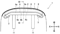
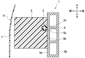
以下、本発明の第1の実施形態の車両用衝突検知装置について、図1〜図7を参照して説明する。図1及び図2に示すように、本実施形態の車両用衝突検知装置1は、中空の検出用チューブ部材2、圧力センサ3、速度センサ4、衝突検知ECU5等を備えて構成される。この車両用衝突検知装置1は、車両前方に設けられたバンパ6への物体(即ち、歩行者)の衝突を検知するものである。このバンパ6は、図3に示すように、バンパカバー7、バンパアブソーバ8、バンパレインフォースメント9を主体として構成されている。
[First Embodiment]
Hereinafter, a vehicle collision detection apparatus according to a first embodiment of the present invention will be described with reference to FIGS. As shown in FIGS. 1 and 2, the vehicle collision detection device 1 of this embodiment includes a hollow detection tube member 2, a pressure sensor 3, a speed sensor 4, a collision detection ECU 5, and the like. This vehicle collision detection apparatus 1 detects a collision of an object (that is, a pedestrian) with a bumper 6 provided in front of the vehicle. As shown in FIG. 3, the bumper 6 is mainly composed of a bumper cover 7, a bumper absorber 8, and a bumper reinforcement 9.

検出用チューブ部材2は、図1及び図2に示すように、内部に中空部2aが形成され、車幅方向(即ち、車両左右方向)に延びているチューブ状の部材である。この検出用チューブ部材2は、図3に示すように、バンパアブソーバ8の後面8bに車幅方向に沿って形成された溝部8aに装着され、バンパレインフォースメント9の前面9aに対向する位置に配設される。検出用チューブ部材2の両端部は、バンパレインフォースメント9の車幅方向左右の外側で湾曲して圧力センサ3に接続される。尚、本実施形態では、検出用チューブ部材2は、後述の通り、その端部の周壁が、図5に示すように圧力センサ3の圧力導入管32に設けられたクリップ部321と圧力導入管32の外周面との間で挟持固定される。   As shown in FIGS. 1 and 2, the detection tube member 2 is a tube-shaped member having a hollow portion 2a formed therein and extending in the vehicle width direction (that is, the vehicle left-right direction). As shown in FIG. 3, the tube member 2 for detection is mounted in a groove 8 a formed in the rear surface 8 b of the bumper absorber 8 along the vehicle width direction, at a position facing the front surface 9 a of the bumper reinforcement 9. Arranged. Both ends of the detection tube member 2 are curved and connected to the pressure sensor 3 on the outer sides of the bumper reinforcement 9 in the vehicle width direction. In the present embodiment, as will be described later, the detection tube member 2 includes a clip portion 321 and a pressure introduction tube whose peripheral wall at the end thereof is provided in the pressure introduction tube 32 of the pressure sensor 3 as shown in FIG. It is clamped between 32 outer peripheral surfaces.

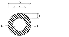
この検出用チューブ部材2は、図7に示すように、円形の断面形状を有し、合成ゴム、例えばシリコーンゴムからなる。検出用チューブ部材2の外径Dは、例えば8mm程度である。また、検出用チューブ部材2の内径dは、例えば4mm程度である。検出用チューブ部材2の周壁の肉厚tは、例えば2mm程度である。尚、検出用チューブ部材2の材質としては、他にもエチレンプロピレンゴム等でもよい。また、検出用チューブ部材2の断面形状は、円形に限られず、楕円形や四角形等でもよい。   As shown in FIG. 7, the tube member for detection 2 has a circular cross-sectional shape and is made of synthetic rubber such as silicone rubber. The outer diameter D of the detection tube member 2 is, for example, about 8 mm. The inner diameter d of the detection tube member 2 is, for example, about 4 mm. The wall thickness t of the peripheral wall of the detection tube member 2 is, for example, about 2 mm. In addition, the material of the detection tube member 2 may be ethylene propylene rubber or the like. Further, the cross-sectional shape of the detection tube member 2 is not limited to a circle, and may be an ellipse or a rectangle.

圧力センサ3は、バンパレインフォースメント9の前面9aよりも車両後方側に配置される。具体的には、圧力センサ3は、バンパカバー7内の左右両端部側に2つ設置され、図示しないが、バンパレインフォースメント9の後面9bにボルト等で締結することにより固定されて取り付けられる。本実施形態では、このように圧力センサ3を2つ設置することにより、冗長性及び検出精度を確保している。   The pressure sensor 3 is disposed on the vehicle rear side with respect to the front surface 9 a of the bumper reinforcement 9. Specifically, two pressure sensors 3 are installed on the left and right ends of the bumper cover 7 and are fixedly attached to the rear surface 9b of the bumper reinforcement 9 with bolts or the like (not shown). . In this embodiment, redundancy and detection accuracy are ensured by installing two pressure sensors 3 in this way.

また、圧力センサ3は、図2に示すように、検出用チューブ部材2の左右両端部に接続され、検出用チューブ部材2の中空部2a内の圧力を検出するように構成される。具体的には、圧力センサ3は、気体の圧力変化を検出するセンサ装置であり、検出用チューブ部材2の中空部2a内の空気の圧力変化を検出する。圧力センサ3は、図1に示すように、伝送線を介して衝突検知ECU5に電気的に接続され、圧力に比例した信号を衝突検知ECU5へ出力する。衝突検知ECU5は、圧力センサ3による圧力検出結果に基づいて、バンパ6への歩行者の衝突を検知する。   Further, as shown in FIG. 2, the pressure sensor 3 is connected to both left and right ends of the detection tube member 2 and is configured to detect the pressure in the hollow portion 2 a of the detection tube member 2. Specifically, the pressure sensor 3 is a sensor device that detects a change in the pressure of gas, and detects a change in the pressure of air in the hollow portion 2 a of the tube member 2 for detection. As shown in FIG. 1, the pressure sensor 3 is electrically connected to the collision detection ECU 5 via a transmission line, and outputs a signal proportional to the pressure to the collision detection ECU 5. The collision detection ECU 5 detects a pedestrian collision with the bumper 6 based on the pressure detection result by the pressure sensor 3.

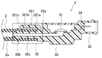
この圧力センサ3は、図4に示すように、本体部30(センサ本体に相当)と、センサ部31と、圧力導入管32と、コネクタ部33と、を備えて構成される。本体部30は、センサ部31を収容するための箱状のケースである。   As shown in FIG. 4, the pressure sensor 3 includes a main body portion 30 (corresponding to a sensor main body), a sensor portion 31, a pressure introduction pipe 32, and a connector portion 33. The main body 30 is a box-shaped case for housing the sensor unit 31.

センサ部31は、圧力検出用のセンサ素子等が設けられた基板等からなり、圧力導入管32を介して検出用チューブ部材2の中空部2a内の圧力変化を検出する。このセンサ部31は、図1に示すように、コネクタ部33に設けられたコネクタ34に電気的に接続されており、圧力に比例した信号をコネクタ34及び信号線を介して衝突検知ECU5へ送信する。   The sensor unit 31 is formed of a substrate or the like provided with a pressure detection sensor element or the like, and detects a pressure change in the hollow portion 2a of the detection tube member 2 via the pressure introduction tube 32. As shown in FIG. 1, the sensor unit 31 is electrically connected to a connector 34 provided in the connector unit 33, and transmits a signal proportional to the pressure to the collision detection ECU 5 via the connector 34 and the signal line. To do.

圧力導入管32は、検出用チューブ部材2内の圧力をセンサ部31に導入するための略円筒状の管であり、本体部30から検出用チューブ部材2の中空部2a内に差し込まれている。圧力導入管32の断面形状は、検出用チューブ部材2の断面形状と相似であり、この場合円形である。尚、圧力導入管32の断面形状は、円形に限られず、楕円形や四角形等でもよい。   The pressure introduction tube 32 is a substantially cylindrical tube for introducing the pressure in the detection tube member 2 into the sensor portion 31, and is inserted from the main body portion 30 into the hollow portion 2 a of the detection tube member 2. . The cross-sectional shape of the pressure introducing tube 32 is similar to the cross-sectional shape of the detection tube member 2 and is circular in this case. The cross-sectional shape of the pressure introducing tube 32 is not limited to a circle, and may be an ellipse or a rectangle.

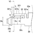
本実施形態の圧力導入管32は、図5及び図6にも示すように、基端部32aと、バルジ部32bと、ポート部32cとを有して構成される。基端部32aは、本体部30の付近に配設され、後述のクリップ部321が突設される。バルジ部32bは、圧力導入管32の先端部に設けられ、先端に向かって外径が小さくなるテーパ形状を有している。バルジ部32bにおける最大直径である外径Dbの長さは、例えば7.2mm程度である。このテーパ形状のバルジ部32bにより、圧力導入管32の先端に検出用チューブ部材2の端部の内側を挿入し易くなっていると共に、検出用チューブ部材2が外れることを防止可能となっている。尚、図5に示される圧力導入管32のポート部32cとバルジ部32bとのなす角αは、90°程度であることが好ましい。   As shown in FIGS. 5 and 6, the pressure introduction pipe 32 of the present embodiment is configured to include a base end portion 32 a, a bulge portion 32 b, and a port portion 32 c. The base end portion 32a is disposed in the vicinity of the main body portion 30, and a later-described clip portion 321 is provided in a protruding manner. The bulge portion 32b is provided at the distal end portion of the pressure introducing tube 32, and has a tapered shape in which the outer diameter decreases toward the distal end. The length of the outer diameter Db which is the maximum diameter in the bulge portion 32b is, for example, about 7.2 mm. The tapered bulge portion 32b makes it easy to insert the inner side of the end portion of the detection tube member 2 into the distal end of the pressure introducing tube 32 and prevents the detection tube member 2 from being detached. . The angle α formed between the port portion 32c and the bulge portion 32b of the pressure introducing pipe 32 shown in FIG. 5 is preferably about 90 °.

ポート部32cは、検出用チューブ部材2を装着するための部位であり、直線状に延びて形成されている。このポート部32cは、検出用チューブ部材2の内径d(即ち4mm程度)よりも大きな外径Dcを有している。具体的には、ポート部32cの外径Dcの長さは、例えば5.5mm程度である。尚、バルジ部32bの外径Dbの長さは、ポート部32cの外径Dcの長さよりも大きければよく、適宜変更可能である。   The port portion 32c is a part for mounting the detection tube member 2, and is formed to extend linearly. The port portion 32c has an outer diameter Dc larger than the inner diameter d (that is, about 4 mm) of the detection tube member 2. Specifically, the length of the outer diameter Dc of the port portion 32c is, for example, about 5.5 mm. In addition, the length of the outer diameter Db of the bulge part 32b should just be larger than the length of the outer diameter Dc of the port part 32c, and can be changed suitably.

そして、本実施形態では、図4〜図6に示すように、圧力導入管32の基端部32aにクリップ部321が突設されている。このクリップ部321は、圧力導入管32のポート部32cの外周に装着された検出用チューブ部材2を圧力導入管32に対して固定するためのものである。クリップ部321は、圧力導入管32の基端部32aから先端側に向かって圧力導入管32の外周面と平行に延設されている。   And in this embodiment, as shown in FIGS. 4-6, the clip part 321 is protrudingly provided by the base end part 32a of the pressure introduction pipe 32. As shown in FIG. The clip portion 321 is for fixing the detection tube member 2 mounted on the outer periphery of the port portion 32 c of the pressure introduction tube 32 to the pressure introduction tube 32. The clip portion 321 extends in parallel with the outer peripheral surface of the pressure introduction tube 32 from the proximal end portion 32 a of the pressure introduction tube 32 toward the distal end side.

具体的には、クリップ部321は、接続部321aと、延設部321bと、突起部321cとを有して構成される。接続部321aは、圧力導入管32の基端部32aに接続されている。この接続部321aは、圧力導入管32の基端部32aから圧力導入管32の軸方向に対して垂直な方向に突設されている。接続部321aの突出長さは、例えば2mm〜5mm程度である。また、延設部321bは、接続部321aから先端側へ向かって、圧力導入管32の軸方向に対して平行な方向に所定の長さだけ延設されている。尚、延設部321bは、圧力導入管32の軸方向に対して全体として略平行であればよく、例えば途中に湾曲した部分を有していてもよいものとする。   Specifically, the clip part 321 includes a connection part 321a, an extension part 321b, and a protrusion part 321c. The connecting portion 321a is connected to the proximal end portion 32a of the pressure introducing pipe 32. The connecting portion 321 a is provided so as to protrude from the base end portion 32 a of the pressure introducing tube 32 in a direction perpendicular to the axial direction of the pressure introducing tube 32. The protruding length of the connecting portion 321a is, for example, about 2 mm to 5 mm. The extending portion 321b extends from the connecting portion 321a toward the distal end side by a predetermined length in a direction parallel to the axial direction of the pressure introducing tube 32. The extended portion 321b may be substantially parallel to the axial direction of the pressure introducing tube 32 as a whole, and may have a curved portion in the middle, for example.

突起部321cは、延設部321bの先端部分において圧力導入管32の外周面側へ突出して設けられ、圧力導入管32の軸方向においてバルジ部32bよりも本体部30に近い側に配置される。この突起部321cは、圧力導入管32のポート部32cに装着された検出用チューブ部材2の外周面と係合する。突起部321cの先端部は、本体部30側へ向かうに従い圧力導入管32側に傾斜したテーパ形状を有している。本実施形態では、この突起部321cと圧力導入管32のバルジ部32bの外周面との間で、検出用チューブ部材2の端部の周壁が挟持固定されるようになっている。   The protruding portion 321c is provided to protrude toward the outer peripheral surface side of the pressure introducing tube 32 at the tip portion of the extending portion 321b, and is disposed closer to the main body portion 30 than the bulge portion 32b in the axial direction of the pressure introducing tube 32. . The protruding portion 321 c engages with the outer peripheral surface of the detection tube member 2 attached to the port portion 32 c of the pressure introducing tube 32. The tip of the protrusion 321c has a tapered shape that is inclined toward the pressure introduction tube 32 as it goes toward the main body 30. In the present embodiment, the peripheral wall of the end portion of the tube member for detection 2 is sandwiched and fixed between the protruding portion 321c and the outer peripheral surface of the bulge portion 32b of the pressure introducing tube 32.

突起部321cとバルジ部32bとは、図5に示すように、圧力導入管32の軸方向に所定間隔Lをあけて配設されている。ここで、間隔Lの長さが短過ぎると検出用チューブ部材2を挿入し難くなるという不具合が生じる。一方、間隔Lの長さが長過ぎるとクリップ部321の突起部321cと圧力導入管32のバルジ部32bとの離間距離が大きくなるので、検出用チューブ部材2の固定強度が十分に得られないことが想定される。本実施形態では、間隔Lの長さを、検出用チューブ部材2の端部の周壁がクリップ部321の突起部321cと圧力導入管32のバルジ部32bの外周面との間に挿入可能な程度の長さであり、且つ検出用チューブ部材2の固定強度を確保可能な長さに設定している。具体的には、間隔Lの長さは、例えば2mm〜3mm程度に設定されている。   As shown in FIG. 5, the protruding portion 321 c and the bulge portion 32 b are arranged at a predetermined interval L in the axial direction of the pressure introducing pipe 32. Here, when the length of the space | interval L is too short, the malfunction that it becomes difficult to insert the tube member 2 for detection arises. On the other hand, if the distance L is too long, the distance between the protrusion 321c of the clip portion 321 and the bulge portion 32b of the pressure introducing tube 32 becomes large, so that the fixing strength of the detection tube member 2 cannot be sufficiently obtained. It is assumed that In the present embodiment, the length of the interval L is such that the peripheral wall at the end of the detection tube member 2 can be inserted between the protrusion 321 c of the clip portion 321 and the outer peripheral surface of the bulge portion 32 b of the pressure introducing tube 32. And a length that can secure the fixing strength of the tube member 2 for detection. Specifically, the length of the interval L is set to about 2 mm to 3 mm, for example.

また、突起部321cの先端部とポート部32cの外周面との離間距離Hは、当該突起部321cがポート部32cに装着された検出用チューブ部材2と確実に当接する長さに設定されている。この場合、離間距離Hの長さは、2mm未満に設定されている。尚、この離間距離Hの長さを適宜調節することにより、突起部321cと検出用チューブ部材2との間の面圧を調節可能となっている。   Further, the separation distance H between the distal end portion of the protruding portion 321c and the outer peripheral surface of the port portion 32c is set to a length that ensures that the protruding portion 321c abuts against the detection tube member 2 attached to the port portion 32c. Yes. In this case, the length of the separation distance H is set to less than 2 mm. The surface pressure between the protrusion 321c and the detection tube member 2 can be adjusted by appropriately adjusting the length of the separation distance H.

速度センサ4は、車両の速度を検出するセンサ装置であり、衝突検知ECU5に信号線を介して電気的に接続されている。この速度センサ4は、車両速度に比例した信号を衝突検知ECU5へ送信する。   The speed sensor 4 is a sensor device that detects the speed of the vehicle, and is electrically connected to the collision detection ECU 5 via a signal line. The speed sensor 4 transmits a signal proportional to the vehicle speed to the collision detection ECU 5.

衝突検知ECU5は、CPUを主体として構成され、車両用衝突検知装置1の動作全般を制御するものであり、図1に示すように、圧力センサ3、速度センサ4、歩行者保護装置10のそれぞれに電気的に接続されている。衝突検知ECU5には、圧力センサ3からの圧力信号、速度センサ4からの速度信号等が入力される。衝突検知ECU5は、圧力センサ3からの圧力信号及び速度センサ4からの速度信号に基づいて、所定の衝突判定処理を実行し、バンパ6のバンパカバー7への歩行者等の物体の衝突を検知した場合には、制御信号を出力して歩行者保護装置10を作動させる。   The collision detection ECU 5 is composed mainly of a CPU and controls the overall operation of the vehicle collision detection apparatus 1. As shown in FIG. 1, each of the pressure sensor 3, the speed sensor 4, and the pedestrian protection apparatus 10. Is electrically connected. The collision detection ECU 5 receives a pressure signal from the pressure sensor 3, a speed signal from the speed sensor 4, and the like. The collision detection ECU 5 executes a predetermined collision determination process based on the pressure signal from the pressure sensor 3 and the speed signal from the speed sensor 4 to detect the collision of an object such as a pedestrian with the bumper cover 7 of the bumper 6. When it does, a control signal is output and the pedestrian protection apparatus 10 is operated.

バンパ6は、車両の衝突時における衝撃を和らげるためのものであり、バンパカバー7、バンパアブソーバ8、バンパレインフォースメント9等から構成される。バンパカバー7は、バンパ6の構成部品を覆うように設けられ、ポリプロピレン等の樹脂製の部材である。このバンパカバー7は、バンパ6の外観を構成すると同時に、車両全体の外観の一部を構成するものとなっている。   The bumper 6 is for reducing an impact at the time of a vehicle collision, and includes a bumper cover 7, a bumper absorber 8, a bumper reinforcement 9, and the like. The bumper cover 7 is provided so as to cover the components of the bumper 6 and is a resin member such as polypropylene. The bumper cover 7 constitutes the appearance of the bumper 6 and at the same time constitutes a part of the appearance of the entire vehicle.

バンパアブソーバ8は、バンパレインフォースメント9の前面9aに対向する位置に配設される。このバンパアブソーバ8は、車両の歩行者等との衝突時にバンパ6において衝撃吸収の作用を受け持つ部材であり、例えば発泡ポリプロピレン等からなる。   The bumper absorber 8 is disposed at a position facing the front surface 9 a of the bumper reinforcement 9. The bumper absorber 8 is a member having an impact absorbing function in the bumper 6 when it collides with a pedestrian or the like of the vehicle, and is made of, for example, foamed polypropylene.

バンパアブソーバ8の後面8bには、図1及び図2に示すように、検出用チューブ部材2を装着するための溝部8aが車幅方向に沿って形成されている。この溝部8aは、図3に示すように、矩形の断面形状を有している。溝部8aの車両前後方向の長さは、検出用チューブ部材2の外径の長さと同等である。また、溝部8aの車両上下方向の長さは、検出用チューブ部材2の外径の長さよりも長くなっている。   As shown in FIGS. 1 and 2, a groove 8a for mounting the detection tube member 2 is formed in the rear surface 8b of the bumper absorber 8 along the vehicle width direction. As shown in FIG. 3, the groove 8a has a rectangular cross-sectional shape. The length of the groove portion 8a in the vehicle front-rear direction is equal to the length of the outer diameter of the detection tube member 2. Further, the length of the groove portion 8a in the vehicle vertical direction is longer than the length of the outer diameter of the detection tube member 2.

バンパレインフォースメント9は、バンパカバー7内に配設されて車幅方向に延びるアルミニウム等の金属製の剛性部材であって、図3に示すように、内部中央に梁が設けられた中空部材である。また、バンパレインフォースメント9は、車両前方側の面である前面9aと、車両後方側の面である後面9bとを有している。このバンパレインフォースメント9は、図1及び図2に示すように、車両前後方向に延びる一対の金属製部材であるサイドメンバ11の前端に取り付けられる。   The bumper reinforcement 9 is a rigid member made of metal such as aluminum which is disposed in the bumper cover 7 and extends in the vehicle width direction. As shown in FIG. It is. The bumper reinforcement 9 has a front surface 9a that is a surface on the front side of the vehicle and a rear surface 9b that is a surface on the rear side of the vehicle. As shown in FIGS. 1 and 2, the bumper reinforcement 9 is attached to the front end of a side member 11 that is a pair of metal members extending in the vehicle front-rear direction.

通常、車両の衝突事故においては、車両の進行方向(即ち、車両前方)に存在する歩行者や車両と衝突する場合が多い。このため、本実施形態では、圧力センサ3をバンパレインフォースメント9の後面9bに配設して、車両前方の歩行者や車両との衝突に伴う衝撃が、車両前方に設けられたバンパカバー7等から圧力センサ3に直接伝わることをバンパレインフォースメント9の存在によって保護している。   Usually, in a vehicle collision accident, there are many cases where the vehicle collides with a pedestrian or a vehicle existing in the traveling direction of the vehicle (that is, in front of the vehicle). For this reason, in this embodiment, the pressure sensor 3 is disposed on the rear surface 9b of the bumper reinforcement 9, and a bumper cover 7 provided with an impact caused by a collision with a pedestrian or vehicle in front of the vehicle is provided in front of the vehicle. The presence of the bumper reinforcement 9 protects the direct transmission to the pressure sensor 3.

尚、図示しないが、バンパアブソーバ8の後面8bに設けられた嵌合凸部が、バンパレインフォースメント9の前面9aに設けられた嵌合凹部に嵌め合わされることにより、バンパアブソーバ8のバンパレインフォースメント9への組付けが行われるものとする。   Although not shown, the fitting convex portion provided on the rear surface 8b of the bumper absorber 8 is fitted into the fitting concave portion provided on the front surface 9a of the bumper reinforcement 9, so that the bumper rain of the bumper absorber 8 is provided. Assume that the assembly to the force 9 is performed.

歩行者保護装置10としては、例えばポップアップフードを用いる。このポップアップフードは、車両の衝突検知後瞬時に、エンジンフードの後端を上昇させ、歩行者とエンジン等の硬い部品とのクリアランスを増加させ、そのスペースを用いて歩行者の頭部への衝突エネルギーを吸収し、歩行者の頭部への衝撃を低減させるものである。尚、ポップアップフードの代わりに、車体外部のエンジンフード上からフロントウインド下部にかけてエアバッグを展開させて歩行者の衝撃を緩衝するカウルエアバッグ等を用いてもよい。   For example, a pop-up hood is used as the pedestrian protection device 10. This pop-up hood raises the rear end of the engine hood instantly after detecting a vehicle collision, increases the clearance between the pedestrian and hard parts such as the engine, and uses that space to collide with the pedestrian's head. It absorbs energy and reduces the impact on the pedestrian's head. Instead of the pop-up hood, a cowl airbag or the like that cushions a pedestrian's impact by deploying an airbag from above the engine hood outside the vehicle body to the lower part of the front window may be used.

次に、本実施形態の車両用衝突検知装置1の製造方法について説明する。本実施形態では、作業者による手作業、又は図示しない治具を用いて、検出用チューブ部材2の圧力センサ3の圧力導入管32への組付け作業が行われる。まず、作業者は、検出用チューブ部材2の端部の内側を、圧力導入管32の先端からバルジ部32bに挿入する。このとき、バルジ部32bが先端に向かって外径が小さくなるテーパ形状を有していることにより、圧力導入管32の先端に検出用チューブ部材2の端部の内側を挿入し易くなっている。また、検出用チューブ部材2の端部の周壁が圧力導入管32の外周側へ拡径する。   Next, a manufacturing method of the vehicle collision detection apparatus 1 of the present embodiment will be described. In this embodiment, the assembly | attachment operation | work to the pressure introduction pipe | tube 32 of the pressure sensor 3 of the tube member 2 for a detection is performed using the operator's manual operation | work or the jig | tool which is not shown in figure. First, the operator inserts the inside of the end portion of the detection tube member 2 into the bulge portion 32 b from the tip of the pressure introducing tube 32. At this time, since the bulge portion 32b has a tapered shape whose outer diameter decreases toward the tip, it is easy to insert the inside of the end portion of the tube member for detection 2 into the tip of the pressure introducing tube 32. . Further, the peripheral wall of the end portion of the tube member for detection 2 is expanded in diameter toward the outer peripheral side of the pressure introducing tube 32.

続いて、作業者は、検出用チューブ部材2の端部を、バルジ部32bの外周面とクリップ部321の突起部321cとの間に挿入する。このとき、突起部321cがテーパ形状を有していることにより、圧力導入管32の先端に検出用チューブ部材2の端部の内側を挿入し易くなっている。また、検出用チューブ部材2の端部の周壁が圧力導入管32の外周側へ拡径する。   Subsequently, the operator inserts the end portion of the detection tube member 2 between the outer peripheral surface of the bulge portion 32 b and the protruding portion 321 c of the clip portion 321. At this time, the protrusion 321 c has a tapered shape, so that the inside of the end of the tube member for detection 2 can be easily inserted into the tip of the pressure introducing tube 32. Further, the peripheral wall of the end portion of the tube member for detection 2 is expanded in diameter toward the outer peripheral side of the pressure introducing tube 32.

バルジ部32bに挿通された後、検出用チューブ部材2の端部は、クリップ部321の突起部321aと係合しながらポート部32c側へ挿入されていく。このとき、バルジ部32bへ挿入されて拡径した検出用チューブ部材2の端部が、突起部321aから面圧を受けながらポート部32cへ案内される。また、突起部321aが本体部30へ向かうに従い圧力導入管32側に傾斜したテーパ形状を有しているので、検出用チューブ部材2に対して適度な面圧を与えながら、検出用チューブ部材2をポート部32cへスムーズに装着可能となっている。   After being inserted through the bulge portion 32b, the end portion of the detection tube member 2 is inserted into the port portion 32c side while engaging with the protruding portion 321a of the clip portion 321. At this time, the end portion of the tube member for detection 2 that has been inserted into the bulge portion 32b and expanded in diameter is guided to the port portion 32c while receiving a surface pressure from the protruding portion 321a. In addition, since the protruding portion 321a has a tapered shape that is inclined toward the pressure introduction tube 32 toward the main body portion 30, the detection tube member 2 is provided with an appropriate surface pressure applied to the detection tube member 2. Can be smoothly attached to the port portion 32c.

更に、作業者が検出用チューブ部材2の端部をポート部32cの奥方側(即ち、接続部321a側)へ挿入していくと、圧力導入管32の基端部32aから圧力導入管32の外周側へ突出して設けられた接続部321aに、検出用チューブ部材2の端部がぶつかる。これにより、圧力導入管32の軸方向における検出用チューブ部材2の挿入量が規制されるようになっている。また、接続部321aから先端側へ向かって延設された延設部321bにより、検出用チューブ部材2が圧力導入管32の外周側へ拡径することを防止している。   Further, when the operator inserts the end portion of the detection tube member 2 into the back side of the port portion 32c (that is, the connection portion 321a side), the pressure introduction tube 32 extends from the proximal end portion 32a of the pressure introduction tube 32. The end portion of the tube member for detection 2 collides with the connecting portion 321a provided to protrude to the outer peripheral side. Thereby, the insertion amount of the tube member for detection 2 in the axial direction of the pressure introducing tube 32 is regulated. Further, the detection tube member 2 is prevented from expanding to the outer peripheral side of the pressure introducing tube 32 by the extending portion 321b extending from the connecting portion 321a toward the distal end side.

このように本実施形態では、圧力導入管32に突設されたクリップ部321と圧力導入管32の外周面との間に検出用チューブ部材2を挿入し、圧力導入管32のポート部32cの外周に検出用チューブ部材2を装着する。これにより、クリップ部321の突起部321cと圧力導入管32のバルジ部32bの外周面との間で、検出用チューブ部材2の端部の周壁を挟持固定し、圧力導入管32に対して検出用チューブ部材2を確実に固定可能となっている。以上により、本実施形態における車両用衝突検知装置1の製造が完了する。   As described above, in this embodiment, the detection tube member 2 is inserted between the clip portion 321 projecting from the pressure introduction tube 32 and the outer peripheral surface of the pressure introduction tube 32, and the port portion 32 c of the pressure introduction tube 32 is inserted. The detection tube member 2 is mounted on the outer periphery. As a result, the peripheral wall of the end portion of the tube member for detection 2 is sandwiched and fixed between the protruding portion 321 c of the clip portion 321 and the outer peripheral surface of the bulge portion 32 b of the pressure introducing tube 32, and the detection is performed on the pressure introducing tube 32. The tube member 2 can be securely fixed. Thus, the manufacture of the vehicle collision detection device 1 in the present embodiment is completed.

次に、本実施形態における車両用衝突検知装置1の衝突時の動作について説明する。車両前方に歩行者等の物体が衝突した際には、バンパ6のバンパカバー7が歩行者との衝突による衝撃により変形する。続いて、バンパアブソーバ8が衝撃を吸収しながら変形すると同時に、検出用チューブ部材2も変形する。このとき、検出用チューブ部材2の中空部2a内の圧力が急上昇し、この圧力変化が圧力センサ3に伝達する。   Next, the operation | movement at the time of the collision of the collision detection apparatus 1 for vehicles in this embodiment is demonstrated. When an object such as a pedestrian collides with the front of the vehicle, the bumper cover 7 of the bumper 6 is deformed by an impact caused by the collision with the pedestrian. Subsequently, the bumper absorber 8 is deformed while absorbing the impact, and at the same time, the detection tube member 2 is also deformed. At this time, the pressure in the hollow portion 2 a of the detection tube member 2 rises rapidly, and this pressure change is transmitted to the pressure sensor 3.

車両用衝突検知装置1の衝突検知ECU5は、圧力センサ3の検知結果に基づいて、所定の衝突判定処理を実行する。この衝突判定処理では、例えば圧力センサ3及び速度センサ4の検出結果に基づいて、衝突物の有効質量を算出し、この有効質量が所定の閾値より大きい場合、歩行者との衝突が発生したものと判定する。更に、車両速度が所定の範囲(例えば時速25km〜55kmの範囲)内である場合に、歩行者保護装置10の作動を要する歩行者との衝突が発生したものと判定する。   The collision detection ECU 5 of the vehicle collision detection device 1 executes a predetermined collision determination process based on the detection result of the pressure sensor 3. In this collision determination processing, for example, the effective mass of the collision object is calculated based on the detection results of the pressure sensor 3 and the speed sensor 4, and when this effective mass is larger than a predetermined threshold, a collision with a pedestrian has occurred. Is determined. Furthermore, when the vehicle speed is within a predetermined range (for example, a range of 25 km to 55 km / h), it is determined that a collision with a pedestrian requiring the operation of the pedestrian protection device 10 has occurred.

ここで、「有効質量」とは、衝突時における圧力センサ3の圧力検出値より、運動量と力積の関係を利用して算出する質量をいう。車両と物体との衝突が発生した場合、歩行者とは質量の異なる衝突物では、検知される圧力センサ3の圧力検出値が異なる。このため、人体の有効質量と、想定される他の衝突物の質量との間に閾値を設定することにより、衝突物の種類を切り分けることが可能となる。この有効質量は、次式に示すように、圧力センサ3により検出される圧力の値の所定時間における定積分値を、速度センサ4により検出される車両速度で割ることにより算出される。
M=(∫P(t)dt)/V・・・(式1)
Here, the “effective mass” refers to a mass calculated using the relationship between momentum and impulse from the pressure detection value of the pressure sensor 3 at the time of collision. When a collision between a vehicle and an object occurs, the detected pressure value of the pressure sensor 3 is different for a collision object having a mass different from that of a pedestrian. For this reason, by setting a threshold value between the effective mass of the human body and the mass of another assumed collision object, it is possible to classify the types of the collision object. This effective mass is calculated by dividing the constant integral value of the pressure value detected by the pressure sensor 3 at a predetermined time by the vehicle speed detected by the speed sensor 4 as shown in the following equation.
M = (∫P (t) dt) / V (Expression 1)

尚、Mは有効質量、Pは所定時間における圧力センサ3による圧力検出値、tは所定時間(例えば、数ms〜数十ms)、Vは速度センサ4により検出される衝突時の車両速度を示している。有効質量を算出する方法には、他にも、衝突した物体の運動エネルギーEを表す式E=1/2・MVを用いて算出することが可能である。この場合、有効質量は、M=2・E/Vにより算出される。 M is an effective mass, P is a pressure detection value by the pressure sensor 3 at a predetermined time, t is a predetermined time (for example, several ms to several tens of ms), V is a vehicle speed at the time of collision detected by the speed sensor 4. Show. As another method for calculating the effective mass, it is possible to calculate using an equation E = 1/2 · MV 2 representing the kinetic energy E of the collided object. In this case, the effective mass is calculated by M = 2 · E / V 2 .

また、本実施形態では、圧力センサ3の圧力導入管32の基端部32aに、クリップ部321が突設されている。圧力導入管32のポート部32cの外周に装着された検出用チューブ部材2端部の周壁は、当該クリップ部321と圧力導入管32の外周面との間で挟持固定されている。このため、衝突時において圧力センサ3の圧力導入管32から検出用チューブ部材2が外れることがなく、正確に衝突検知が可能となっている。   In the present embodiment, a clip portion 321 projects from the proximal end portion 32 a of the pressure introduction pipe 32 of the pressure sensor 3. The peripheral wall of the end portion of the detection tube member 2 mounted on the outer periphery of the port portion 32 c of the pressure introducing tube 32 is sandwiched and fixed between the clip portion 321 and the outer peripheral surface of the pressure introducing tube 32. For this reason, the detection tube member 2 is not detached from the pressure introduction pipe 32 of the pressure sensor 3 at the time of the collision, and the collision can be accurately detected.

そして、衝突検知ECU5は、歩行者保護装置10の作動を要する歩行者との衝突が発生したと判定した場合、歩行者保護装置10を作動させる制御信号を出力し、歩行者保護装置10を作動させて、上述したように歩行者への衝撃を低減させる。   When the collision detection ECU 5 determines that a collision has occurred with a pedestrian that requires the pedestrian protection device 10 to operate, the collision detection ECU 5 outputs a control signal for operating the pedestrian protection device 10 to operate the pedestrian protection device 10. To reduce the impact on the pedestrian as described above.

以上説明したように、第1の実施形態の車両用衝突検知装置1は、車両のバンパ6内に配設されて内部に中空部2aが形成された検出用チューブ部材2と、検出用チューブ部材2の端部が装着され且つ中空部2a内の圧力をセンサ本体30に導入する圧力導入管32を具備して中空部2a内の圧力を検出する圧力センサ3と、を有し、圧力センサ3による圧力検出結果に基づいてバンパ6への物体(即ち、歩行者)の衝突を検知する。そして、圧力導入管32の基端部32a側から先端側に向かって外周面と平行に延設され、且つ圧力導入管32の外周に装着された検出用チューブ部材2の周壁を圧力導入管32の外周面との間で挟持固定するクリップ部321を備えている。   As described above, the vehicle collision detection device 1 according to the first embodiment includes the detection tube member 2 disposed in the vehicle bumper 6 and having the hollow portion 2a formed therein, and the detection tube member. And a pressure sensor 3 for detecting the pressure in the hollow portion 2a. The pressure sensor 3 is provided with a pressure introduction pipe 32 that is attached to the end portion 2 and introduces the pressure in the hollow portion 2a into the sensor body 30. The collision of an object (ie, a pedestrian) with the bumper 6 is detected based on the pressure detection result by. The pressure introduction tube 32 extends from the base end portion 32 a side of the pressure introduction tube 32 toward the distal end side in parallel with the outer peripheral surface and the peripheral wall of the detection tube member 2 attached to the outer circumference of the pressure introduction tube 32. The clip part 321 clamped and fixed between the outer peripheral surfaces is provided.

この構成によれば、圧力導入管32の外周に装着された検出用チューブ部材2の周壁を、圧力導入管32の基端部32aの外周面から先端側へ向かって延設されたクリップ部321と圧力導入管32の外周面との間で挟持固定することができるので、別体の固定用部材(例えば、クランプ等)を設けることなく、圧力センサ3の圧力導入管32に対して検出用チューブ部材2を確実に固定することができ、圧力センサ3の圧力導入管32から検出用チューブ部材2が外れることを確実に防止できる。   According to this configuration, the clip portion 321 that extends from the outer peripheral surface of the base end portion 32 a of the pressure introduction tube 32 toward the distal end side of the peripheral wall of the detection tube member 2 attached to the outer periphery of the pressure introduction tube 32. And the outer peripheral surface of the pressure introducing tube 32, and therefore, for detection with respect to the pressure introducing tube 32 of the pressure sensor 3 without providing a separate fixing member (for example, a clamp). The tube member 2 can be reliably fixed, and the detection tube member 2 can be reliably prevented from being detached from the pressure introduction tube 32 of the pressure sensor 3.

また、クリップ部321は、圧力導入管32の基端部32aに接続される接続部321aと、接続部321aから先端側へ向かって延びる延設部321bと、延設部321bの先端部分において圧力導入管32の外周面側へ突出する突起部321cと、を有して構成される。   In addition, the clip portion 321 includes a connecting portion 321a connected to the proximal end portion 32a of the pressure introducing tube 32, an extending portion 321b extending from the connecting portion 321a toward the distal end side, and a pressure at a distal end portion of the extending portion 321b. And a protruding portion 321 c that protrudes toward the outer peripheral surface side of the introduction pipe 32.

この構成によれば、検出用チューブ部材2の端部を圧力導入管32へ装着する際に、検出用チューブ部材2の端部が、圧力導入管32の基端部32aに接続された接続部321aにぶつかるので、圧力導入管32に対する検出用チューブ部材2の挿入量を規制でき、製造時における挿入量の管理が容易となる。また、接続部321aから先端側へ向かって延設された延設部321bにより、検出用チューブ部材2の端部の周壁が圧力導入管32の外周側へ拡径することを防ぐことができる。更に、延設部321bの先端部分において圧力導入管32の外周面側へ突出した突起部321cが、検出用チューブ部材2の外周面と係合することにより、検出用チューブ部材2への面圧を高めることができ、検出用チューブ部材2を突起部321cと圧力導入管32の外周面との間でより確実に挟持固定できる。   According to this configuration, when the end portion of the detection tube member 2 is attached to the pressure introduction tube 32, the connection portion in which the end portion of the detection tube member 2 is connected to the proximal end portion 32 a of the pressure introduction tube 32. Since it hits 321a, the insertion amount of the tube member for detection 2 with respect to the pressure introducing pipe 32 can be regulated, and the management of the insertion amount at the time of manufacture becomes easy. In addition, the extending portion 321 b extending from the connecting portion 321 a toward the distal end side can prevent the peripheral wall of the end portion of the detection tube member 2 from expanding to the outer peripheral side of the pressure introducing tube 32. Further, the protrusion 321c protruding to the outer peripheral surface side of the pressure introducing tube 32 at the distal end portion of the extending portion 321b engages with the outer peripheral surface of the detection tube member 2, whereby the surface pressure applied to the detection tube member 2 is increased. Thus, the detection tube member 2 can be more securely sandwiched and fixed between the protrusion 321c and the outer peripheral surface of the pressure introducing tube 32.

また、圧力導入管32は、検出用チューブ部材2の端部が装着されるポート部32cと、その先端部に設けられポート部32cの外径Dcよりも大きい外径を有するバルジ部32bと、を有して構成される。検出用チューブ部材2は、その端部の周壁がクリップ部321の突起部321aと圧力導入管32のバルジ部32bの外周面との間で挟持固定される。   The pressure introduction pipe 32 includes a port portion 32c to which an end portion of the tube member for detection 2 is attached, a bulge portion 32b that is provided at the tip portion and has an outer diameter larger than the outer diameter Dc of the port portion 32c, It is comprised. The peripheral wall of the end portion of the detection tube member 2 is sandwiched and fixed between the protruding portion 321a of the clip portion 321 and the outer peripheral surface of the bulge portion 32b of the pressure introducing tube 32.

この構成によれば、ポート部32cに装着された検出用チューブ部材2の端部の周壁を、クリップ部321の突起部321aと圧力導入管32のバルジ部32bの外周面との間で挟持固定することで、圧力導入管32に対して検出用チューブ部材2をより確実に固定できる。特に、圧力導入管32のバルジ部32bは、ポート部32cの外径Dcよりも大きい外径Dbを有しているので、検出用チューブ部材2と圧力導入管32の外周面との面圧を大きくして、圧力導入管32に対する検出用チューブ部材2の固定強度を向上できる。   According to this configuration, the peripheral wall of the end portion of the detection tube member 2 attached to the port portion 32c is clamped and fixed between the protruding portion 321a of the clip portion 321 and the outer peripheral surface of the bulge portion 32b of the pressure introducing tube 32. By doing so, the tube member for detection 2 can be more reliably fixed to the pressure introducing tube 32. In particular, since the bulge portion 32b of the pressure introduction tube 32 has an outer diameter Db larger than the outer diameter Dc of the port portion 32c, the surface pressure between the detection tube member 2 and the outer peripheral surface of the pressure introduction tube 32 is increased. The fixing strength of the detection tube member 2 with respect to the pressure introduction pipe 32 can be increased.

また、突起部321aとバルジ部32bとは、圧力導入管32の軸方向に所定間隔Lをあけて配設されている。この構成によれば、突起部321aとバルジ部32bとが圧力導入管32の軸方向に所定間隔Lをあけて配設されているので、検出用チューブ部材2の端部を、バルジ部32bの外周面とクリップ部321の突起部321cとの間に確実に挿入可能である。   Further, the protruding portion 321a and the bulge portion 32b are disposed at a predetermined interval L in the axial direction of the pressure introducing pipe 32. According to this configuration, since the protruding portion 321a and the bulge portion 32b are disposed at a predetermined interval L in the axial direction of the pressure introducing tube 32, the end portion of the detection tube member 2 is connected to the bulge portion 32b. It can be reliably inserted between the outer peripheral surface and the protrusion 321 c of the clip portion 321.

また、バルジ部32bは、先端に向かって径が小さくなるテーパ形状を有している。この構成によれば、バルジ部32bが先端に向かって径が小さくなるテーパ形状を有しているので、検出用チューブ部材2の端部をテーパ形状のバルジ部32bに沿って圧力導入管32へ挿入することで、検出用チューブ部材2を圧力導入管32へ装着し易くできる。また、検出用チューブ部材2が圧力センサ3の本体部30から離れる方向に移動した際に、検出用チューブ部材2とバルジ部32bとの間の摩擦が大きくなる構造となっているので、検出用チューブ部材2が圧力センサ3から外れることを防止できる。   Moreover, the bulge part 32b has a taper shape in which a diameter becomes small toward the front-end | tip. According to this configuration, since the bulge portion 32b has a tapered shape whose diameter decreases toward the tip, the end portion of the detection tube member 2 is connected to the pressure introducing tube 32 along the tapered bulge portion 32b. By inserting, the detection tube member 2 can be easily attached to the pressure introducing tube 32. In addition, when the detection tube member 2 moves in a direction away from the main body 30 of the pressure sensor 3, the friction between the detection tube member 2 and the bulge portion 32b increases. The tube member 2 can be prevented from coming off from the pressure sensor 3.

また、突起部321aは、圧力導入管32の軸方向においてバルジ部32bよりも本体部30に近い側に設けられ、本体部30へ向かうに従い圧力導入管32側に傾斜したテーパ形状を有している。この構成によれば、突起部321aが本体部30へ向かうに従い圧力導入管32側に傾斜したテーパ形状を有しているので、検出用チューブ部材2をポート部32cへ確実に案内することができる。また、バルジ部32bへ挿入されて拡径した検出用チューブ部材2を、突起部321aによって面圧を与えて圧力導入管32側へ押圧することで、検出用チューブ部材2をポート部32cに確実に装着できる。   The protrusion 321a is provided on the side closer to the main body 30 than the bulge 32b in the axial direction of the pressure introduction pipe 32, and has a tapered shape inclined toward the pressure introduction pipe 32 toward the main body 30. Yes. According to this configuration, since the protruding portion 321a has a tapered shape inclined toward the pressure introducing tube 32 as it goes to the main body portion 30, the detection tube member 2 can be reliably guided to the port portion 32c. . Further, the detection tube member 2 inserted into the bulge portion 32b and expanded in diameter is given a surface pressure by the projection 321a and pressed toward the pressure introduction tube 32, so that the detection tube member 2 is securely attached to the port portion 32c. Can be attached to.

また、圧力導入管32のポート部32cの外径Dcは、検出用チューブ部材2の内径dよりも大きく設定されている。この構成によれば、検出用チューブ部材2が装着されるポート部32cの外径Dcが検出用チューブ部材2の内径dよりも大きいので、圧力導入管32と検出用チューブ部材2との接続部分の密閉性を高めることができる。   Further, the outer diameter Dc of the port portion 32 c of the pressure introducing pipe 32 is set larger than the inner diameter d of the detection tube member 2. According to this configuration, since the outer diameter Dc of the port portion 32c to which the detection tube member 2 is mounted is larger than the inner diameter d of the detection tube member 2, the connection portion between the pressure introducing tube 32 and the detection tube member 2 The hermeticity can be improved.

[第2の実施形態]
次に、本発明の第2の実施形態について、図8〜図10を参照して説明する。尚、図8〜図10において上記第1の実施形態と同一部分には同一の符号を付して説明を省略し、異なる部分についてだけ説明する。圧力導入管32における互いに対向する位置に一対のクリップ部322が突設されている点が、第1の実施形態と異なる。
[Second Embodiment]
Next, a second embodiment of the present invention will be described with reference to FIGS. 8 to 10, the same parts as those in the first embodiment are denoted by the same reference numerals, description thereof is omitted, and only different parts are described. The point from which a pair of clip part 322 is protrudingly provided in the position which mutually opposes in the pressure introduction pipe 32 differs from 1st Embodiment.

第2の実施形態のクリップ部322は、図8及び図9に示すように、圧力導入管32における互いに対向する位置に2つのクリップ部322が設けられている。このクリップ部322は、図10にも示すように、圧力導入管32の基端部32aに2箇所突設されている。これら2つのクリップ部322は、圧力導入管32の基端部32aから外周側へ突出し、圧力導入管32の先端側へ向かって延設されている。尚、クリップ部322の配設位置や配置個数は、適宜変更可能であるものとする。   As shown in FIGS. 8 and 9, the clip portion 322 of the second embodiment is provided with two clip portions 322 at positions facing each other in the pressure introduction pipe 32. As shown in FIG. 10, the clip portion 322 is protruded at two locations on the proximal end portion 32 a of the pressure introducing pipe 32. These two clip portions 322 protrude from the proximal end portion 32 a of the pressure introduction tube 32 to the outer peripheral side and extend toward the distal end side of the pressure introduction tube 32. In addition, the arrangement | positioning position and arrangement | positioning number of the clip part 322 can be changed suitably.

クリップ部322は、第1の実施形態と同様に、接続部322aと、延設部322bと、突起部322cとを有して構成される。接続部322aは、圧力導入管32の基端部32aから外周側へ、圧力導入管32の軸方向に対して垂直な方向に突出して設けられている。接続部322aの突出長さは、例えば2mm〜5mm程度である。また、延設部322bは、接続部322aから先端側へ向かって、圧力導入管32の軸方向に対して平行な方向に所定長さだけ延設されている。   Similar to the first embodiment, the clip portion 322 includes a connecting portion 322a, an extending portion 322b, and a protruding portion 322c. The connecting portion 322a is provided so as to protrude from the proximal end portion 32a of the pressure introducing tube 32 to the outer peripheral side in a direction perpendicular to the axial direction of the pressure introducing tube 32. The protruding length of the connecting portion 322a is, for example, about 2 mm to 5 mm. The extending portion 322b extends from the connecting portion 322a toward the distal end side by a predetermined length in a direction parallel to the axial direction of the pressure introducing tube 32.

また、突起部322cは、延設部322bの先端部分において圧力導入管32の外周面側へ突出して設けられ、圧力導入管32の軸方向においてバルジ部32bよりも本体部30に近い側配置される。この突起部322cは、圧力導入管32のポート部32cに装着された検出用チューブ部材2の外周面と係合する。突起部322cの先端部は、本体部30側へ向かうに従い圧力導入管32側に傾斜したテーパ形状を有している。本実施形態では、この突起部322cと圧力導入管32のバルジ部32bの外周面との間で、検出用チューブ部材2の端部の周壁が挟持固定されるようになっている。   Further, the protruding portion 322c is provided to protrude toward the outer peripheral surface side of the pressure introducing tube 32 at the tip portion of the extending portion 322b, and is disposed on the side closer to the main body portion 30 than the bulge portion 32b in the axial direction of the pressure introducing tube 32. The The protrusion 322 c engages with the outer peripheral surface of the detection tube member 2 attached to the port portion 32 c of the pressure introducing tube 32. The tip of the protrusion 322c has a tapered shape that is inclined toward the pressure introduction tube 32 as it goes toward the main body 30. In the present embodiment, the peripheral wall of the end portion of the tube member for detection 2 is sandwiched and fixed between the protruding portion 322c and the outer peripheral surface of the bulge portion 32b of the pressure introducing tube 32.

また、突起部322cとバルジ部32bとは、図9に示すように、圧力導入管32の軸方向に所定間隔Lをあけて配設されている。この間隔Lの長さは、検出用チューブ部材2の端部の周壁が、クリップ部322と圧力導入管32の外周面との間に挿入可能な程度の長さに設定されている。また、突起部322cの先端部とポート部32cの外周面との離間距離Hは、当該突起部322cがポート部32cに装着された検出用チューブ部材2と確実に当接する長さに設定されている。   Further, as shown in FIG. 9, the protruding portion 322 c and the bulge portion 32 b are disposed at a predetermined interval L in the axial direction of the pressure introducing pipe 32. The length of the interval L is set to such a length that the peripheral wall at the end of the detection tube member 2 can be inserted between the clip portion 322 and the outer peripheral surface of the pressure introducing tube 32. In addition, the separation distance H between the tip of the protrusion 322c and the outer peripheral surface of the port 32c is set to a length that ensures that the protrusion 322c contacts the detection tube member 2 attached to the port 32c. Yes.

以上説明した第2の実施形態の車両用衝突検知装置1では、クリップ部322は、圧力導入管32における互いに対向する位置に一対で設けられ、検出用チューブ部材2の端部の周壁を圧力導入管32の外周面との間で2箇所挟持固定するものである。   In the vehicle collision detection apparatus 1 according to the second embodiment described above, the clip portions 322 are provided as a pair at positions facing each other in the pressure introduction pipe 32, and pressure is introduced to the peripheral wall at the end of the detection tube member 2. Two places are clamped between the outer peripheral surface of the pipe 32 and fixed.

この第2の実施形態の車両用衝突検知装置1においても、第1の実施形態と同様の効果を得ることができる。特に、圧力導入管32における互いに対向する位置に一対で設けられた2つのクリップ部322によって、検出用チューブ部材2の端部の周壁を2箇所で挟持固定することで、圧力導入管32に対して検出用チューブ部材2をより確実に固定することができる。   In the vehicle collision detection device 1 of the second embodiment, the same effect as that of the first embodiment can be obtained. In particular, the peripheral wall of the end portion of the detection tube member 2 is clamped and fixed at two locations by two clip portions 322 provided in pairs at positions facing each other in the pressure introduction tube 32, so that the pressure introduction tube 32 is fixed. Thus, the detection tube member 2 can be more reliably fixed.

[第3の実施形態]
次に、本発明の第3の実施形態について、図11及び図12を参照して説明する。尚、図9及び図10において上記第1の実施形態と同一部分には同一の符号を付して説明を省略し、異なる部分についてだけ説明する。
[Third Embodiment]
Next, a third embodiment of the present invention will be described with reference to FIGS. In FIG. 9 and FIG. 10, the same parts as those in the first embodiment are denoted by the same reference numerals, description thereof is omitted, and only different parts will be described.

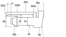
この第3の実施形態においては、図11及び図12に示すように、クリップ部323の突起部323cが、圧力導入管32の軸方向においてバルジ部32bよりも本体部30から遠い側に設けられている。即ち、クリップ部323の延設部323bが、第1の実施形態の延設部321bよりも長く延びて設けられ、突起部323cよりもバルジ部32bの方が本体部30から近い側に配置されている。また、突起部323cは、テーパ形状を有していない構成となっている。   In the third embodiment, as shown in FIGS. 11 and 12, the protruding portion 323 c of the clip portion 323 is provided on the side farther from the body portion 30 than the bulge portion 32 b in the axial direction of the pressure introducing pipe 32. ing. That is, the extending portion 323b of the clip portion 323 is provided to extend longer than the extending portion 321b of the first embodiment, and the bulge portion 32b is disposed closer to the main body portion 30 than the protruding portion 323c. ing. Further, the protruding portion 323c does not have a tapered shape.

クリップ部323は、第1の実施形態と同様に、接続部323aと、延設部323bと、突起部323cとを有して構成される。接続部323aは、圧力導入管32の基端部32bに接続されている。この接続部323aは、圧力導入管32の基端部32aから圧力導入管32の軸方向に対して垂直な方向に突設されている。接続部323aの突出長さは、例えば2mm〜5mm程度である。また、延設部323bは、接続部322aから圧力導入管32の軸方向に対して平行な方向に延出し、バルジ部32bよりも本体部30から遠い側まで延びている。   Similar to the first embodiment, the clip part 323 includes a connection part 323a, an extension part 323b, and a protrusion part 323c. The connecting portion 323a is connected to the proximal end portion 32b of the pressure introducing pipe 32. The connection portion 323 a is provided so as to protrude from the base end portion 32 a of the pressure introduction pipe 32 in a direction perpendicular to the axial direction of the pressure introduction pipe 32. The protruding length of the connecting portion 323a is, for example, about 2 mm to 5 mm. The extending portion 323b extends from the connecting portion 322a in a direction parallel to the axial direction of the pressure introducing pipe 32, and extends to a side farther from the main body portion 30 than the bulge portion 32b.

また、突起部323cは、延設部323bの先端部分において圧力導入管32の外周面側へ突出して設けられ、圧力導入管32の軸方向においてバルジ部32bよりも本体部30から遠い側に配置される。この突起部323cは、圧力導入管32のポート部32cに装着された検出用チューブ部材2の外周面と係合する。突起部323cの先端部は、圧力導入管32の軸方向に平行な形状を有している。この突起部323cと圧力導入管32のバルジ部32bの外周面との間で、検出用チューブ部材2の端部の周壁が挟持固定される。   Further, the protrusion 323c is provided at the distal end portion of the extending portion 323b so as to protrude to the outer peripheral surface side of the pressure introduction tube 32, and is disposed on the side farther from the main body 30 than the bulge portion 32b in the axial direction of the pressure introduction tube 32 Is done. The protrusion 323 c engages with the outer peripheral surface of the detection tube member 2 attached to the port portion 32 c of the pressure introduction pipe 32. The tip of the protrusion 323 c has a shape parallel to the axial direction of the pressure introducing tube 32. Between the projection 323c and the outer peripheral surface of the bulge portion 32b of the pressure introducing tube 32, the peripheral wall of the end portion of the tube member for detection 2 is sandwiched and fixed.

また、突起部323cとバルジ部32bとは、図12に示すように、圧力導入管32の軸方向に所定間隔Lをあけて配設されている。この間隔Lの長さは、検出用チューブ部材2の端部の周壁が、クリップ部323と圧力導入管32の外周面との間に挿入可能な程度の長さに設定されている。また、突起部323cの先端部とポート部32cの外周面との離間距離Hは、当該突起部323cがポート部32cに装着された検出用チューブ部材2と確実に当接する長さに設定されている。   Further, as shown in FIG. 12, the protruding portion 323 c and the bulge portion 32 b are disposed at a predetermined interval L in the axial direction of the pressure introducing pipe 32. The length of the interval L is set to such a length that the peripheral wall at the end of the detection tube member 2 can be inserted between the clip portion 323 and the outer peripheral surface of the pressure introducing tube 32. Further, the separation distance H between the tip of the protrusion 323c and the outer peripheral surface of the port 32c is set to a length that ensures that the protrusion 323c abuts the detection tube member 2 attached to the port 32c. Yes.

次に、第3の実施形態の車両用衝突検知装置1の製造方法について説明する。第3の実施形態では、まず、作業者は、検出用チューブ部材2の端部を、クリップ部323の突起部323cとバルジ部32bの外周面との間に挿入する。続いて、検出用チューブ部材2の端部を、圧力導入管32の先端からバルジ部32bに挿入し、ポート部32cの奥方側(即ち、接続部323a側)へ挿入していく。このとき、バルジ部32bが先端に向かって外径が小さくなるテーパ形状を有していることにより、圧力導入管32の先端に検出用チューブ部材2の端部の内側を挿入し易くなっている。バルジ部32bに挿通された後、検出用チューブ部材2の端部は、圧力導入管32のポート部32cに装着される。   Next, a method for manufacturing the vehicle collision detection apparatus 1 according to the third embodiment will be described. In the third embodiment, first, the operator inserts the end portion of the detection tube member 2 between the protruding portion 323c of the clip portion 323 and the outer peripheral surface of the bulge portion 32b. Subsequently, the end portion of the detection tube member 2 is inserted into the bulge portion 32b from the distal end of the pressure introducing tube 32 and inserted into the back side of the port portion 32c (that is, the connection portion 323a side). At this time, since the bulge portion 32b has a tapered shape whose outer diameter decreases toward the tip, it is easy to insert the inside of the end portion of the tube member for detection 2 into the tip of the pressure introducing tube 32. . After being inserted through the bulge portion 32 b, the end portion of the detection tube member 2 is attached to the port portion 32 c of the pressure introducing tube 32.

更に、作業者が検出用チューブ部材2の端部をポート部32cの奥方側(即ち、接続部323a側)へ挿入していくと、圧力導入管32の基端部32aから圧力導入管32の外周側へ突出して設けられた接続部323aに、検出用チューブ部材2の端部がぶつかる。これにより、圧力導入管32の軸方向における検出用チューブ部材2の挿入量が規制されるようになっている。また、接続部323aから先端側へ向かって延設された延設部323bにより、検出用チューブ部材2が圧力導入管32の外周側へ拡径することを防止している。以上により、第3の実施形態における車両用衝突検知装置1の製造が完了する。   Furthermore, when the operator inserts the end portion of the tube member for detection 2 into the back side of the port portion 32c (that is, the connection portion 323a side), the pressure introduction tube 32 extends from the proximal end portion 32a of the pressure introduction tube 32. The end portion of the tube member for detection 2 collides with the connection portion 323a provided so as to protrude to the outer peripheral side. Thereby, the insertion amount of the tube member for detection 2 in the axial direction of the pressure introducing tube 32 is regulated. Further, the extension tube 323 b extending from the connection portion 323 a toward the distal end side prevents the detection tube member 2 from expanding to the outer peripheral side of the pressure introduction tube 32. Thus, the manufacture of the vehicle collision detection device 1 in the third embodiment is completed.

以上説明した第3の実施形態の車両用衝突検知装置1では、圧力導入管32の軸方向においてクリップ部323の突起部323cは、バルジ部32bより本体部30から遠い側に設けられている。この第3の実施形態の車両用衝突検知装置1においても、第1の実施形態と同様の効果を得ることができる。   In the vehicle collision detection apparatus 1 according to the third embodiment described above, the protruding portion 323c of the clip portion 323 is provided on the side farther from the main body portion 30 than the bulge portion 32b in the axial direction of the pressure introduction pipe 32. In the vehicle collision detection apparatus 1 of the third embodiment, the same effect as that of the first embodiment can be obtained.

[その他の実施形態]
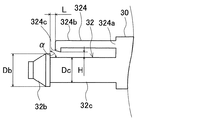
本発明は、上記した実施形態に限定されるものではなく、本発明の主旨を逸脱しない範囲で種々の変形又は拡張を施すことができる。例えば、上記実施形態では、クリップ部321〜323において、接続部321a〜323aが圧力導入管32の基端部32aに接続されるものとしたが、これに限られない。図13及び図14に示すように、クリップ部324の接続部324aが、圧力センサ3の本体部30に接続される構成でもよい。即ち、クリップ部324が、圧力センサ3の本体部30から延設されていてもよい。尚、クリップ部324は、接続部324aと延設部324bと突起部324cとを有して構成され、当該クリップ部324の突起部324cと圧力導入管32のバルジ部32bの外周面との間で検出用チューブ部材2が挟持固定される。この場合も、上記実施形態と同様の効果を得ることができる。
[Other Embodiments]
The present invention is not limited to the above-described embodiment, and various modifications or expansions can be made without departing from the spirit of the present invention. For example, in the above-described embodiment, the connection portions 321a to 323a are connected to the proximal end portion 32a of the pressure introducing pipe 32 in the clip portions 321 to 323, but the present invention is not limited thereto. As shown in FIGS. 13 and 14, the connection portion 324 a of the clip portion 324 may be connected to the main body portion 30 of the pressure sensor 3. That is, the clip part 324 may be extended from the main body part 30 of the pressure sensor 3. The clip portion 324 includes a connection portion 324a, an extension portion 324b, and a projection portion 324c, and is formed between the projection portion 324c of the clip portion 324 and the outer peripheral surface of the bulge portion 32b of the pressure introduction pipe 32. Thus, the detection tube member 2 is clamped and fixed. Also in this case, the same effect as the above embodiment can be obtained.

また、上記実施形態では、クリップ部321〜323の延設部321b〜323bと、ポート部32cに装着された検出用チューブ部材2の外周面との間に隙間がある構成としたが、これに限られない。クリップ部321〜323の延設部321b〜323bと検出用チューブ部材2の外周面とが当接していてもよい。この場合、クリップ部321〜323と検出用チューブ部材2の外周面との接触面積が大きくなるので、圧力導入管32に対する検出用チューブ部材2の固定強度を向上できる。   Moreover, in the said embodiment, although it was set as the structure which has a clearance gap between the extended parts 321b-323b of the clip parts 321-323, and the outer peripheral surface of the tube member 2 for a detection with which the port part 32c was mounted | worn, Not limited. The extending portions 321 b to 323 b of the clip portions 321 to 323 may be in contact with the outer peripheral surface of the detection tube member 2. In this case, since the contact area between the clip portions 321 to 323 and the outer peripheral surface of the detection tube member 2 is increased, the fixing strength of the detection tube member 2 to the pressure introduction tube 32 can be improved.

また、クリップ部321〜323は、圧力導入管32の外周面に装着された検出用チューブ部材2の周壁を圧力導入管32の外周面との間で挟持固定可能なものであればよく、突起部321c〜323cがない構成であってもよい。   Further, the clip portions 321 to 323 may be any ones that can sandwich and fix the peripheral wall of the detection tube member 2 attached to the outer peripheral surface of the pressure introducing tube 32 between the outer peripheral surface of the pressure introducing tube 32 and the protrusions. The structure which does not have the parts 321c-323c may be sufficient.

また、圧力導入管32のバルジ部32bがテーパ形状であるものとしたが、バルジ部32bは、ポート部32cよりも外径が大きく、検出用チューブ部材2の挿入を阻害しない外形形状であればよく、テーパ形状でなくてもよい。   In addition, the bulge portion 32b of the pressure introducing tube 32 has a tapered shape, but the bulge portion 32b has an outer diameter larger than that of the port portion 32c and has an outer shape that does not hinder insertion of the detection tube member 2. It does not have to be tapered.

また、上記実施形態では、衝突判定処理において、有効質量が所定の閾値以上になった場合に歩行者保護装置10の作動を要する歩行者との衝突が発生したと判定するものとしたが、これに限られない。例えば、圧力センサ3により検出された圧力の値、圧力変化率等を衝突判定の閾値として用いてもよい。   In the above embodiment, in the collision determination process, it is determined that a collision with a pedestrian that requires the operation of the pedestrian protection device 10 has occurred when the effective mass exceeds a predetermined threshold. Not limited to. For example, a pressure value detected by the pressure sensor 3, a pressure change rate, or the like may be used as a threshold for collision determination.

1 車両用衝突検知装置
2 検出用チューブ部材
2a 中空部
3 圧力センサ
32 圧力導入管
32a 基端部
32b バルジ部
32c ポート部
321,322,323,324 クリップ部
321a,322a,323a,324a 接続部
321b,322b,323b,324b 延設部
321c,322c,323c,324c 突起部
6 バンパ
7 バンパカバー
8 バンパアブソーバ
9 バンパレインフォースメント
DESCRIPTION OF SYMBOLS 1 Vehicle collision detection apparatus 2 Detection tube member 2a Hollow part 3 Pressure sensor 32 Pressure introduction pipe 32a Base end part 32b Bulge part 32c Port part 321,322,323,324 Clip part 321a, 322a, 323a, 324a connection part 321b , 322b, 323b, 324b Extension part 321c, 322c, 323c, 324c Projection part 6 Bumper 7 Bumper cover 8 Bumper absorber 9 Bumper reinforcement

Claims (10)

車両のバンパ(6)内に配設されて内部に中空部(2a)が形成された検出用チューブ部材(2)と、前記検出用チューブ部材の端部が装着され且つ前記中空部内の圧力をセンサ本体(30)に導入する圧力導入管(32)を具備して前記中空部内の圧力を検出する圧力センサ(3)と、を有し、前記圧力センサによる圧力検出結果に基づいて前記バンパへの物体の衝突を検知する車両用衝突検知装置(1)であって、
前記圧力導入管の基端側から先端側に向かって外周面と平行に延設され、且つ前記圧力導入管の外周に装着された前記検出用チューブ部材の周壁を前記圧力導入管の外周面との間で挟持固定するクリップ部(321,322,323,324)を備えた車両用衝突検知装置。
A detection tube member (2) disposed in a vehicle bumper (6) and having a hollow portion (2a) formed therein, an end of the detection tube member is mounted, and the pressure in the hollow portion is reduced. A pressure sensor (3) that includes a pressure introduction pipe (32) that introduces into the sensor body (30) and detects the pressure in the hollow portion, and that is supplied to the bumper based on a pressure detection result by the pressure sensor. A vehicle collision detection device (1) for detecting a collision of an object,
The peripheral wall of the tube member for detection that extends in parallel with the outer peripheral surface from the proximal end side to the distal end side of the pressure introduction tube and is attached to the outer periphery of the pressure introduction tube is defined as the outer peripheral surface of the pressure introduction tube. The collision detection apparatus for vehicles provided with the clip part (321,322,323,324) pinched and fixed between.
前記クリップ部は、前記圧力導入管の前記基端部又は前記センサ本体に接続される接続部(321a,322a,323a,324a)と、前記接続部から先端側へ向かって延びる延設部(321b,322b,323b,324b)と、前記延設部の先端部分において前記圧力導入管の外周面側へ突出する突起部(321c,322c,323c,324c)と、を有して構成される請求項1に記載の車両用衝突検知装置。   The clip portion includes a connection portion (321a, 322a, 323a, 324a) connected to the base end portion of the pressure introduction pipe or the sensor body, and an extension portion (321b) extending from the connection portion toward the distal end side. , 322b, 323b, 324b) and protrusions (321c, 322c, 323c, 324c) protruding toward the outer peripheral surface side of the pressure introducing pipe at the distal end portion of the extending portion. The vehicle collision detection device according to claim 1. 前記圧力導入管は、前記検出用チューブ部材の端部が装着されるポート部(32c)と、その先端部に設けられ前記ポート部の外径(Dc)よりも大きい外径(Db)を有するバルジ部(32b)と、を有して構成され、
前記検出用チューブ部材は、その端部の周壁が前記クリップ部の前記突起部と前記圧力導入管の前記バルジ部の外周面との間で挟持固定される請求項2に記載の車両用衝突検知装置。
The pressure introducing pipe has a port portion (32c) to which an end portion of the detection tube member is mounted, and an outer diameter (Db) that is provided at the distal end portion and is larger than the outer diameter (Dc) of the port portion. A bulge portion (32b),
3. The vehicle collision detection according to claim 2, wherein a peripheral wall of the end portion of the tube member for detection is sandwiched and fixed between the projection portion of the clip portion and the outer peripheral surface of the bulge portion of the pressure introducing tube. apparatus.
前記突起部と前記バルジ部とは、前記圧力導入管の軸方向に所定間隔(L)をあけて配設されている請求項3に記載の車両用衝突検知装置。   The vehicle collision detection device according to claim 3, wherein the protrusion and the bulge are disposed at a predetermined interval (L) in the axial direction of the pressure introduction pipe. 前記バルジ部は、先端に向かって径が小さくなるテーパ形状を有している請求項3または4に記載の車両用衝突検知装置。   5. The vehicle collision detection device according to claim 3, wherein the bulge portion has a tapered shape whose diameter decreases toward the tip. 前記突起部(321c,322c,324c)は、前記センサ本体側へ向かうに従い前記圧力導入管側に傾斜したテーパ形状を有している請求項2から5のいずれか一項に記載の車両用衝突検知装置。   6. The vehicle collision according to claim 2, wherein the protrusions (321 c, 322 c, 324 c) have a tapered shape that is inclined toward the pressure introduction pipe toward the sensor body. Detection device. 前記突起部(321c,322c,324c)は、前記圧力導入管の軸方向において前記バルジ部よりも前記センサ本体に近い側に設けられている請求項3から6のいずれか一項に記載の車両用衝突検知装置。   The vehicle according to any one of claims 3 to 6, wherein the protrusions (321c, 322c, 324c) are provided closer to the sensor body than the bulge portion in the axial direction of the pressure introducing pipe. Collision detection device. 前記突起部(323c)は、前記圧力導入管の軸方向において前記バルジ部よりも前記センサ本体から遠い側に設けられている請求項3から6のいずれか一項に記載の車両用衝突検知装置。   The collision detection device for a vehicle according to any one of claims 3 to 6, wherein the protrusion (323c) is provided on a side farther from the sensor body than the bulge portion in the axial direction of the pressure introducing pipe. . 前記クリップ部(322)は、前記圧力導入管における互いに対向する位置に一対で設けられ、前記検出用チューブ部材の端部の周壁を前記圧力導入管の外周面との間で2箇所挟持固定するものである請求項1から8のいずれか一項に記載の車両用衝突検知装置。   The clip portions (322) are provided as a pair at positions facing each other in the pressure introduction tube, and the peripheral wall of the end portion of the detection tube member is sandwiched and fixed between the outer peripheral surface of the pressure introduction tube at two locations. The vehicle collision detection device according to any one of claims 1 to 8. 前記圧力導入管の前記ポート部の外径(Dc)は、前記検出用チューブ部材の内径(d)よりも大きく設定されている請求項3から9のいずれか一項に記載の車両用衝突検知装置。   The vehicle collision detection according to any one of claims 3 to 9, wherein an outer diameter (Dc) of the port portion of the pressure introducing pipe is set larger than an inner diameter (d) of the detection tube member. apparatus.
JP2016052421A 2016-03-16 2016-03-16 Collision detection device for vehicle Pending JP2017165265A (en)

Priority Applications (3)

Application Number Priority Date Filing Date Title
JP2016052421A JP2017165265A (en) 2016-03-16 2016-03-16 Collision detection device for vehicle
PCT/JP2017/005063 WO2017159158A1 (en) 2016-03-16 2017-02-13 Collision detection device for vehicle
DE112017001360.7T DE112017001360B4 (en) 2016-03-16 2017-02-13 Collision detection device for a vehicle

Applications Claiming Priority (1)

Application Number Priority Date Filing Date Title
JP2016052421A JP2017165265A (en) 2016-03-16 2016-03-16 Collision detection device for vehicle

Publications (2)

Publication Number Publication Date
JP2017165265A true JP2017165265A (en) 2017-09-21
JP2017165265A5 JP2017165265A5 (en) 2018-06-07

Family

ID=59851242

Family Applications (1)

Application Number Title Priority Date Filing Date
JP2016052421A Pending JP2017165265A (en) 2016-03-16 2016-03-16 Collision detection device for vehicle

Country Status (3)

Country Link
JP (1) JP2017165265A (en)
DE (1) DE112017001360B4 (en)
WO (1) WO2017159158A1 (en)

Cited By (2)

* Cited by examiner, † Cited by third party
Publication number Priority date Publication date Assignee Title
CN112867639A (en) * 2018-10-10 2021-05-28 Zf主动安全和电子美国有限公司 Acceleration sensor
JP7404963B2 (en) 2020-03-24 2023-12-26 株式会社デンソー Tube type collision detection sensor

Families Citing this family (1)

* Cited by examiner, † Cited by third party
Publication number Priority date Publication date Assignee Title
CN112697335B (en) * 2020-12-09 2022-07-12 芜湖玉泰汽车制动有限公司 Detection device convenient to detect brake pump pressure

Citations (5)

* Cited by examiner, † Cited by third party
Publication number Priority date Publication date Assignee Title
JPH11141418A (en) * 1997-11-06 1999-05-25 Toyota Motor Corp Surge tank
JP2010058657A (en) * 2008-09-03 2010-03-18 Denso Corp Vehicular collision detection device
JP2010069978A (en) * 2008-09-17 2010-04-02 Denso Corp Collision detection device for vehicle
JP2015217876A (en) * 2014-05-20 2015-12-07 株式会社デンソー Pressure sensor
JP2015219174A (en) * 2014-05-20 2015-12-07 株式会社デンソー Pressure sensor packaging structure

Family Cites Families (9)

* Cited by examiner, † Cited by third party
Publication number Priority date Publication date Assignee Title
DE3843995C2 (en) * 1987-08-20 1997-06-05 Inventa Ag Quick connection for connecting a hose or pipe
DE4209795A1 (en) * 1992-03-26 1993-09-30 Continental Ag Hose connection as used in vehicle engines - has tension device pressing hose end axially against hose pipe which has conical outer sleeve face tapering towards open end.
DE9311672U1 (en) * 1993-08-05 1993-10-21 Haupt Hartmut Dr Device for securing a hose on a hose connector
DE20217151U1 (en) * 2002-11-07 2003-01-30 Beul Aba Gmbh Connection fitting for hoses has sleeve with thread in concentric bore and by which sleeve is screwed onto hose end up to collar on sleeve, and has connecting piece consisting of support extension and connector concentrically joining it
DE102005057780A1 (en) * 2005-12-02 2007-06-06 Dbk David + Baader Gmbh Fluid coupling assembly with electrical connector assembly
DE202010000431U1 (en) * 2010-03-22 2011-08-11 Salzgitter Mannesmann Stahlhandel Gmbh joint assembly
DE202011110919U1 (en) 2011-02-22 2017-03-27 Continental Automotive Gmbh Impact sensor with an elastically deformable hose and at least one pressure sensor
JP6494959B2 (en) 2014-09-03 2019-04-03 蛇の目ミシン工業株式会社 Sewing system, sewing machine, terminal device, content display method in sewing machine system, sewing machine program, terminal device program
DE202015106514U1 (en) * 2015-11-30 2016-01-07 Alfons Markert + Co. Gmbh hose connection

Patent Citations (5)

* Cited by examiner, † Cited by third party
Publication number Priority date Publication date Assignee Title
JPH11141418A (en) * 1997-11-06 1999-05-25 Toyota Motor Corp Surge tank
JP2010058657A (en) * 2008-09-03 2010-03-18 Denso Corp Vehicular collision detection device
JP2010069978A (en) * 2008-09-17 2010-04-02 Denso Corp Collision detection device for vehicle
JP2015217876A (en) * 2014-05-20 2015-12-07 株式会社デンソー Pressure sensor
JP2015219174A (en) * 2014-05-20 2015-12-07 株式会社デンソー Pressure sensor packaging structure

Cited By (2)

* Cited by examiner, † Cited by third party
Publication number Priority date Publication date Assignee Title
CN112867639A (en) * 2018-10-10 2021-05-28 Zf主动安全和电子美国有限公司 Acceleration sensor
JP7404963B2 (en) 2020-03-24 2023-12-26 株式会社デンソー Tube type collision detection sensor

Also Published As

Publication number Publication date
DE112017001360T5 (en) 2018-11-29
WO2017159158A1 (en) 2017-09-21
DE112017001360B4 (en) 2020-06-04

Similar Documents

Publication Publication Date Title
US10668881B2 (en) Collision detection device for vehicle
JP6375978B2 (en) Vehicle collision detection device
JP6233651B2 (en) Vehicle collision detection device
JP2015093579A (en) Collision detection device for vehicle
WO2017159158A1 (en) Collision detection device for vehicle
JP6375907B2 (en) Vehicle collision detection device
JP6201909B2 (en) Vehicle collision detection device
JP6376402B2 (en) Vehicle collision detection device
JP6372691B2 (en) Vehicle collision detection device
US20180079381A1 (en) Collision detection device for vehicle
WO2016084362A1 (en) Vehicle collision sensing device
JP2015074389A (en) Collision detection device for vehicle
JP6432376B2 (en) Vehicle collision detection device
JP6500532B2 (en) Vehicle collision detector
JP2017144806A (en) Collision detection device for vehicle and manufacturing method therefor
JP6323722B2 (en) Vehicle collision detection device
JP6406054B2 (en) Vehicle collision detection device
JP2016120867A (en) Collision detection device for vehicle
JP6447303B2 (en) Vehicle collision detection device
JP6443686B2 (en) Vehicle collision detection device
JP6443272B2 (en) Vehicle collision detection device
WO2016157734A1 (en) Vehicle collision detection device
JP6504077B2 (en) Vehicle collision detector

Legal Events

Date Code Title Description
A521 Request for written amendment filed

Free format text: JAPANESE INTERMEDIATE CODE: A523

Effective date: 20180423

A621 Written request for application examination

Free format text: JAPANESE INTERMEDIATE CODE: A621

Effective date: 20180424

A131 Notification of reasons for refusal

Free format text: JAPANESE INTERMEDIATE CODE: A131

Effective date: 20190305

A02 Decision of refusal

Free format text: JAPANESE INTERMEDIATE CODE: A02

Effective date: 20191031