JP2017129340A - Heat source control system, control method and control device - Google Patents
Heat source control system, control method and control device Download PDFInfo
- Publication number
- JP2017129340A JP2017129340A JP2016010982A JP2016010982A JP2017129340A JP 2017129340 A JP2017129340 A JP 2017129340A JP 2016010982 A JP2016010982 A JP 2016010982A JP 2016010982 A JP2016010982 A JP 2016010982A JP 2017129340 A JP2017129340 A JP 2017129340A
- Authority
- JP
- Japan
- Prior art keywords
- chilled water
- primary
- cold water
- return
- temperature
- Prior art date
- Legal status (The legal status is an assumption and is not a legal conclusion. Google has not performed a legal analysis and makes no representation as to the accuracy of the status listed.)
- Granted
Links
Images


Abstract
Description
本発明は、1次冷水ポンプおよび2次冷水ポンプを用いる1次2次ポンプ方式の熱源制御システム、制御方法および制御装置に関する。 The present invention relates to a primary secondary pump type heat source control system, a control method, and a control device using a primary chilled water pump and a secondary chilled water pump.
空調設備における熱源制御システムの配管方式の1つとして、往ヘッダおよび還ヘッダを境として冷凍機側と空調負荷側の揚程を2種類のポンプで分け合う1次2次ポンプ方式が従来から知られている。1次2次ポンプ方式の配管方式では、複数台の冷凍機の各々に対して、空調負荷(熱交換器)にて熱交換され昇温されて還ってくる2次冷水を還ヘッダを経て1次冷水として送り出す複数台の1次冷水ポンプと、冷凍機からの1次冷水を空調負荷に対して往ヘッダを経て往2次冷水として送り出す2次冷水ポンプとが設けられる。1次冷水ポンプは、1次冷水を還ヘッダから冷凍機、冷凍機から往ヘッダへと循環するのに、往ヘッダ及び還ヘッダまでの配管抵抗と冷凍機の水圧損分との合計を揚程として受け持つものであり、2次冷水ポンプは、冷水2次往配管および冷水2次還配管の配管抵抗と空調負荷の熱交換器部分の水圧損分との合計を揚程として受け持つ。なお、往ヘッダおよび還ヘッダはバイパス管で接続されている。 As one of the piping systems of the heat source control system in the air conditioning equipment, a primary secondary pump system in which the heads on the refrigerator side and the air conditioning load side are divided by two types of pumps with the forward header and the return header as a boundary has been conventionally known. Yes. In the piping system of the primary secondary pump system, the secondary chilled water that is heated and returned by the air conditioning load (heat exchanger) is returned to each of the plurality of refrigerators through the return header. There are provided a plurality of primary chilled water pumps for sending out the secondary chilled water and a secondary chilled water pump for sending the primary chilled water from the refrigerator as the outgoing secondary chilled water to the air conditioning load through the outgoing header. The primary chilled water pump circulates the primary chilled water from the return header to the freezer, and from the freezer to the forward header, with the sum of the pipe resistance from the forward header and the return header and the water pressure loss of the refrigerator as the head. The secondary chilled water pump is responsible for the sum of the pipe resistance of the chilled water secondary outgoing pipe and the chilled water secondary return pipe and the water pressure loss of the heat exchanger portion of the air conditioning load. The forward header and the return header are connected by a bypass pipe.
ここで、1次2次ポンプ方式の熱源制御システムの設計では、空調負荷の熱交換器への冷水供給温度の制御目標値を1次側の冷凍機冷水出口温度でとることが通例であり、運転時の実際の2次冷水往温度は、各冷凍機における冷凍機冷水出口温度および1次冷水流量や、バイパス管からの流れ等によって成り行きで温度が決まる。そのため、上記の熱源制御システムの制御では、基本的には冷凍機冷水出口温度の1次冷水がそのままの温度で往ヘッダから空調負荷に送り出されるように、定常状態において1次冷水流量が2次冷水流量よりも多くなるような制御が行われる。1次冷水流量が2次冷水流量よりも多い場合には、その差分の流量はバイパス管を経由して冷凍機に戻ることとなり、往ヘッダから還ヘッダへ冷水の流れが生じる(以下の説明では、バイパス管内の往ヘッダから還ヘッダへの流れを正流とする)。 Here, in the design of the primary secondary pump type heat source control system, it is customary to take the control target value of the chilled water supply temperature to the heat exchanger of the air conditioning load at the chiller outlet temperature on the primary side, The actual secondary chilled water temperature during operation is determined by the chiller chilled water outlet temperature and the primary chilled water flow rate in each refrigerator, the flow from the bypass pipe, and the like. Therefore, in the above control of the heat source control system, the primary chilled water flow rate is basically the secondary chilled water flow rate in the steady state so that the primary chilled water at the chiller chilled water outlet temperature is sent from the forward header to the air conditioning load at the same temperature. Control is performed so as to be greater than the cold water flow rate. When the primary chilled water flow rate is larger than the secondary chilled water flow rate, the difference flow rate returns to the refrigerator via the bypass pipe, and the flow of chilled water is generated from the forward header to the return header (in the following explanation). The flow from the forward header to the return header in the bypass pipe is a positive flow).
一方、2次冷水往温度と2次冷水還温度との差(2次冷水温度差ΔT2)がその設計値(例えばΔT2=5℃)よりも小さい場合、2次冷水流量が増加する。これは、変流量定温度差方式としての熱源流量制御システムを組んだ場合で、負荷の変動に関わらず2次冷水温度差ΔT2が設計値となるべきところ、実際には負荷の小さくなる中間期、冬期になるに従って2次冷水温度差ΔT2が小さくなったりする事柄を指している。このような小温度差となってしまう原因として、2次側の多数ある空調負荷の、制御弁差圧や制御弁サイズの過大、熱交換器であるコイル流量の過大などがあり、理想的な状況とはならない現場も多数ある。
これにより、1次側総冷熱量と2次側総熱量とを合致させて設計2次冷水温度差ΔT2から演算した、大温度差が確保できている2次冷水流量に基づいて決まる1次冷水流量にて1次側を変流量制御していると、実際の2次冷水流量が1次冷水流量よりも多くなる場合が生じる。
On the other hand, when the difference between the secondary chilled water going temperature and the secondary chilled water return temperature (secondary chilled water temperature difference ΔT2) is smaller than the design value (for example, ΔT2 = 5 ° C.), the secondary chilled water flow rate increases. This is a case where a heat source flow rate control system as a variable flow rate constant temperature difference method is assembled, where the secondary chilled water temperature difference ΔT2 should be the design value regardless of the load variation, but in the intermediate period when the load actually decreases. This indicates that the secondary cold water temperature difference ΔT2 becomes smaller as the winter season begins. The causes of such a small temperature difference include an excessive control valve differential pressure and control valve size, an excessive coil flow rate that is a heat exchanger, etc. for a large number of air conditioning loads on the secondary side. There are many sites that are not in the situation.
As a result, the primary chilled water determined based on the secondary chilled water flow rate with which a large temperature difference can be secured, which is calculated from the design secondary chilled water temperature difference ΔT2 by matching the primary total chilled heat amount with the secondary side total chilled heat amount. When the primary side is controlled to change the flow rate by the flow rate, the actual secondary chilled water flow rate may be larger than the primary chilled water flow rate.
その結果として、2次冷水流量が1次冷水流量よりも多くなると、還ヘッダの温度の高い冷水がバイパス管を介して往ヘッダに逆流し、2次冷水往温度が上昇することで空調負荷を構成する空調機での冷房能力が低下するおそれがある。そのため、2次冷水往温度が上昇する場合には、停止している熱源(冷凍機)を追加起動させて1次側の冷水循環量を増加させることで、バイパス管における還ヘッダから往ヘッダへの逆流を防止する対策が講じられる。 As a result, when the secondary chilled water flow rate is higher than the primary chilled water flow rate, the chilled water having a high return header temperature flows back to the forward header through the bypass pipe, and the secondary chilled water forward temperature rises to reduce the air conditioning load. There exists a possibility that the cooling capacity in the air conditioner to comprise may fall. Therefore, when the secondary chilled water temperature rises, the heat source (refrigerator) that is stopped is additionally activated to increase the amount of chilled water circulation on the primary side, so that the return header in the bypass pipe goes to the forward header. Measures are taken to prevent backflow.
従来の技術において、2次冷水往温度を冷凍機冷水出口温度に維持すべく、還ヘッダから往ヘッダへの逆流を防止するために冷水1次流量を増加させる場合には、1次冷水ポンプにおける1次冷水の搬送動力の増大や熱源の運転台数の増加等により、余計なエネルギーが消費されるおそれがある。変流量定温度差方式の熱源流量制御システムを組んでいれば、負荷の変動に関わらず2次冷水温度差ΔT2が設計値となるべきところ、実際には2次冷水温度差ΔT2が小さくなっている事柄を受けて、さらに1次冷水流量を増加させるのは、設計時のポンプ搬送動力や設計時の熱源運転動力や運転台数を大きく増加させていることに他ならない。 In the prior art, in order to maintain the secondary chilled water going temperature at the refrigerator chilled water outlet temperature, in order to prevent the reverse flow from the return header to the going header, the chilled water primary flow rate is increased in the primary chilled water pump. Excessive energy may be consumed due to an increase in the conveyance power of primary cold water or an increase in the number of operating heat sources. If a variable flow constant temperature difference type heat source flow rate control system is built, the secondary chilled water temperature difference ΔT2 should be the design value regardless of load fluctuations, but the secondary chilled water temperature difference ΔT2 actually decreases. In response to this, the primary chilled water flow rate is further increased by greatly increasing the pump conveyance power at the time of design, the heat source operation power at the time of design, and the number of units operated.
また、上記のように空調負荷が要求する必要な冷熱量が同じ状況で1次冷水流量を増加させると、1次冷水出口温度と1次冷水入口温度との差(1次冷水温度差ΔT1)が小さくなるが、1次冷水温度差ΔT1が小さくなると、冷凍機としては軽負荷運転状態となり圧縮機の能力を絞っても蒸発器から圧縮機への吸入量を絞ることが出来ず、吸入過剰状態から蒸発圧力低下による、冷水凍結という故障防止のため、冷凍機側盤の安全回路により冷凍機のコンプレッサを停止させる制御が行われ、冷凍機コンプレッサの再起動には一定時間のインターバルが必要なため、冷凍機のコンプレッサが停止したときには2次冷水往温度が上昇してしまう。 In addition, when the flow rate of the primary chilled water is increased in the situation where the required amount of cooling required by the air conditioning load is the same as described above, the difference between the primary chilled water outlet temperature and the primary chilled water inlet temperature (primary chilled water temperature difference ΔT1). However, if the primary chilled water temperature difference ΔT1 is reduced, the refrigerator will be in a light load operation state, and even if the capacity of the compressor is reduced, the intake amount from the evaporator to the compressor cannot be reduced, and excessive intake In order to prevent cold water freezing failure due to the evaporation pressure drop from the state, the safety circuit of the refrigerator side panel is controlled to stop the compressor of the refrigerator, and a certain time interval is required to restart the refrigerator compressor For this reason, when the compressor of the refrigerator is stopped, the secondary cold water going temperature rises.
これらの問題を解決するために、往ヘッダと還ヘッダ間のバイパス管内を、還ヘッダから往ヘッダへ温度が高くなった2次還冷水を流入させる逆流を許容することで、1次冷水流量を2次冷水流量よりも大きくしなくてすむ、適正な1次冷水流量を目指す熱源制御システムが、わずかながら存在する。 In order to solve these problems, the flow rate of the primary chilled water can be reduced by allowing a reverse flow in which the secondary return chilled water having a high temperature flows from the return header to the forward header in the bypass pipe between the forward header and the return header. There are a few heat source control systems that aim for an appropriate primary chilled water flow that does not need to be greater than the secondary chilled water flow.
例えば、特許文献1には、一次流量制御を実行する制御手段が、冷凍機からの送出熱媒とバイパス管からの二次還り熱媒との混合により負荷機器の適正入口熱媒温度となるバイパス利用一次流量制御において、二次流量に対する一次流量の比率である運転流量比率を制御するのに、負荷機器の入口熱媒温度の計測値と所要の目標状態に処理する適正入口熱媒温度との偏差に応じて、その偏差の解消側に一次流量を調整することが開示されている。
For example, in
また、特許文献2には、往一次ヘッダと往二次ヘッダとからなる往ヘッダと、還一次ヘッダと還二次ヘッダとからなる還ヘッダとの間に、各ヘッダの内部熱媒の混合の良好な箇所にバランス管を配置して、往ヘッダ内の熱媒の温度を検出する熱源水温度検出手段、還流水一次温度検出手段、還流水二次温度検出手段およびバランス管内水温検出手段によって検出された温度に基づいて熱源の温度制御および熱源ポンプによる流量制御を行う制御手段を備えることで、送水温度が上昇した冷水を空調負荷に送ることを防止し、負荷が増え二次側の還流水がバランス管を、還ヘッダから往ヘッダへと流れる逆流を速やかに検知し、冷凍機からの熱媒の温度制御を実行すること、が開示されている。
Further, in
しかし、特許文献1では、負荷機器の入出口熱媒温度差が設計値よりも小さくなる原因である、中間期などで負荷機器の入口熱媒温度が相対的に過剰能力の温度になる状況については、何ら具体的な説明がなく、負荷機器で処理対象を所要の目標状態に処理することが可能で且つ処理に必要な限界温度寄りである適正入口熱媒温度については、熱源システム構成機器の特性情報に基づく所定の決定方法によると、概念だけ示して具体的には記載がない。
However, in
さらに、特許文献1では、熱源ユニット側の熱媒流量である一次流量は、二次流量に対する一次流量の比率である運転流量比率は、100%より増側にも減側にも調整可能とはしているものの、負荷機器の入口熱媒温度の計測値と、設定値である適正入口熱媒温度との偏差でしか調整しないもので、冷凍機の出口温度下限値や流量下限値に付いて考慮していないので、冷凍機の安全回路を動作させかねず、熱源制御としては不完全なものである。
Furthermore, in
そして、特許文献2では、熱源水温度検出手段、還流水一次温度検出手段、還流水二次温度検出手段およびバランス管内水温検出手段という、均一に混合している箇所に温度計を設置することが困難なヘッダやヘッダ間バランス管内の温度計測値に頼り、その温度計測値を用いた複雑な演算により、あくまでバランス管内の逆流をできるだけ防止することを主眼とした熱源制御システムである。
And in
このように、これら従来技術においても、1次2次ポンプ方式における2次冷水往温度に新たに制御目標値を設けた熱源制御システムとして、1次冷水出口温度の最適化や1次冷水流量の最適化による、空調負荷へ一定温度で供給しなければならない2次冷水往温度の安定制御を行ないつつ、1次冷水の搬送動力の省エネルギー制御にはなお改善の余地があった。 As described above, in these prior arts as well, as a heat source control system in which a control target value is newly set for the secondary chilled water feed temperature in the primary secondary pump system, the primary chilled water outlet temperature is optimized and the primary chilled water flow rate is adjusted. There is still room for improvement in the energy-saving control of the primary chilled water conveyance power while performing the stable control of the secondary chilled water feed temperature that must be supplied to the air conditioning load at a constant temperature by optimization.
本発明の目的は、従来の制御では成り行きで決定されていた2次冷水往温度を安定的に制御し、従来と比べて1次冷水ポンプにおける1次冷水の搬送動力の増大や熱源の運転台数増加を抑制し易く、冷凍機のコンプレッサも停止しにくくなる熱源制御システム、制御方法および制御装置を提供することにある。 The object of the present invention is to stably control the secondary chilled water temperature, which has been determined according to the circumstances in the conventional control, and to increase the transport power of the primary chilled water in the primary chilled water pump and the number of operating heat sources. It is an object of the present invention to provide a heat source control system, a control method, and a control device that make it easy to suppress an increase and make it difficult to stop a compressor of a refrigerator.
本発明の一例である熱源制御システムは、冷凍機と、前記冷凍機の冷水出口側に冷水1次往配管で接続される第1往ヘッダと、1次冷水ポンプを介して、前記冷凍機の冷水入口側に冷水1次還配管で接続される還ヘッダと、前記第1往ヘッダと前記還ヘッダとを接続するバイパス管と、2次冷水ポンプを介して、前記第1往ヘッダに往ヘッダ配管で接続される第2往ヘッダと、前記第2往ヘッダと前記還ヘッダとの間に冷水2次往配管及び冷水2次還配管を介して接続される空調負荷と、前記第2往ヘッダ又は前記冷水2次往配管に2次往温度計と、前記還ヘッダ又は前記冷水2次還配管に2次還温度計と、前記冷水2次還配管に2次流量計と、前記冷凍機および前記1次冷水ポンプを制御する制御装置と、を備える。そして、前記制御装置は、前記空調負荷の出口の前記2次還温度計と前記空調負荷の入口の前記2次往温度計の計測値の差である2次冷水温度差が設計値未満となるときに、前記2次還温度計と前記2次往温度計と前記2次流量計の各計測値から算出した2次側の負荷熱量と、前記2次冷水還温度計測値と冷凍機冷水出口温度と1次冷水流量から計算で求める1次側の生成熱量とが等しくなる条件で、かつ前記1次冷水ポンプが送水する1次冷水と、前記バイパス管を介して前記還ヘッダから前記第1往ヘッダへ流入する2次還冷水とが合流した2次冷水往温度が制御目標値である2次冷水往温度の設定値となるように、前記2次冷水往温度の設定値と、前記2次冷水還温度と、前記2次冷水流量を用いて、冷凍機冷水出口温度を制御するための第1の制御設定値と、1次冷水流量を制御するための第2の制御設定値とを求め、前記第1の制御設定値および前記第2の制御設定値に基づいて前記冷凍機および前記1次冷水ポンプを制御する。 A heat source control system as an example of the present invention includes a refrigerator, a first outgoing header connected to the cold water outlet side of the refrigerator by a cold water primary outgoing pipe, and a primary cold water pump. A return header connected to the cold water inlet side by a cold water primary return pipe, a bypass pipe connecting the first forward header and the return header, and a secondary cold water pump to the forward header to the first forward header A second forward header connected by piping, an air conditioning load connected between the second forward header and the return header via a chilled water secondary forward piping and a chilled water secondary return piping, and the second forward header Or a secondary return thermometer in the cold water secondary return pipe, a secondary return thermometer in the return header or the cold water secondary return pipe, a secondary flow meter in the cold water secondary return pipe, the refrigerator, and A control device for controlling the primary cold water pump. And the said control apparatus becomes less than a design value the secondary chilled water temperature difference which is a difference of the measured value of the said secondary return thermometer of the exit of the said air conditioning load, and the said secondary going thermometer of the entrance of the said air conditioning load. Sometimes, the secondary load heat quantity calculated from the measured values of the secondary return thermometer, the secondary forward thermometer, and the secondary flow meter, the secondary cold water return temperature measurement value, and the refrigerator cold water outlet The primary chilled water sent by the primary chilled water pump under conditions where the temperature and the primary-side generated heat quantity calculated from the primary chilled water flow rate are equal, and the first header from the return header via the bypass pipe The set value of the secondary chilled water feed temperature and the second chilled water feed temperature so that the secondary chilled water feed temperature joined with the secondary return chilled water flowing into the feed header becomes the set value of the secondary chilled water feed temperature, which is the control target value. Using the secondary cold water return temperature and the secondary cold water flow rate, the refrigerator cold water outlet temperature is controlled. A first control set value and a second control set value for controlling the primary chilled water flow rate, and the refrigerator and the second control set value based on the first control set value and the second control set value. The primary chilled water pump is controlled.
本発明の一例である熱源制御システムの制御方法は、冷凍機と、前記冷凍機の冷水出口側に冷水1次往配管で接続される第1往ヘッダと、1次冷水ポンプを介して、前記冷凍機の冷水入口側に冷水1次還配管で接続される還ヘッダと、前記第1往ヘッダと前記還ヘッダとを接続するバイパス管と、2次冷水ポンプを介して、前記第1往ヘッダに往ヘッダ配管で接続される第2往ヘッダと、前記第2往ヘッダと前記還ヘッダとの間に冷水2次往配管及び冷水2次還配管を介して接続される空調負荷と、前記第2往ヘッダ又は前記冷水2次往配管に2次往温度計と、前記還ヘッダ又は前記冷水2次還配管に2次還温度計と、前記冷水2次還配管に2次流量計と、制御装置と、を備える熱源制御システムに適用される。上記の制御方法では、前記空調負荷の出口の前記2次還温度計と前記空調負荷の入口の前記2次往温度計の計測値の差である2次冷水温度差が設計値未満となるときに、前記2次還温度計と前記2次往温度計と前記2次流量計の各計測値から算出した2次側の負荷熱量と、前記2次冷水還温度計測値と冷凍機冷水出口温度と1次冷水流量から計算で求める1次側の生成熱量とが等しくなる条件で、かつ前記1次冷水ポンプが送水する1次冷水と、前記バイパス管を介して前記還ヘッダから前記第1往ヘッダへ流入する2次還冷水とが合流した2次冷水往温度が制御目標値である2次冷水往温度の設定値となるように、前記制御装置が、前記2次冷水往温度の設定値と、前記2次冷水還温度と、前記2次冷水流量を用いて、冷凍機冷水出口温度を制御するための第1の制御設定値と、1次冷水流量を制御するための第2の制御設定値とを求め、前記制御装置が、前記第1の制御設定値および前記第2の制御設定値に基づいて前記冷凍機および前記1次冷水ポンプを制御する。
本発明の一例である制御装置は、冷凍機と、前記冷凍機の冷水出口側に冷水1次往配管で接続される第1往ヘッダと、1次冷水ポンプを介して、前記冷凍機の冷水入口側に冷水1次還配管で接続される還ヘッダと、前記第1往ヘッダと前記還ヘッダとを接続するバイパス管と、2次冷水ポンプを介して、前記第1往ヘッダに往ヘッダ配管で接続される第2往ヘッダと、前記第2往ヘッダと前記還ヘッダとの間に冷水2次往配管及び冷水2次還配管を介して接続される空調負荷と、前記第2往ヘッダ又は前記冷水2次往配管に2次往温度計と、前記還ヘッダ又は前記冷水2次還配管に2次還温度計と、前記冷水2次還配管に2次流量計と、を備える熱源制御システムに適用される。上記の制御装置は、前記空調負荷の出口の前記2次還温度計と前記空調負荷の入口の前記2次往温度計の計測値の差である2次冷水温度差が設計値未満となるときに、前記2次還温度計と前記2次往温度計と前記2次流量計の各計測値から算出した2次側の負荷熱量と、前記2次冷水還温度計測値と冷凍機冷水出口温度と1次冷水流量から計算で求める1次側の生成熱量とが等しくなる条件で、かつ前記1次冷水ポンプが送水する1次冷水と、前記バイパス管を介して前記還ヘッダから前記第1往ヘッダへ流入する2次還冷水とが合流した2次冷水往温度が制御目標値である2次冷水往温度の設定値となるように、前記2次冷水往温度の設定値と、前記2次冷水還温度と、前記2次冷水流量を用いて、冷凍機冷水出口温度を制御するための第1の制御設定値と、1次冷水流量を制御するための第2の制御設定値とを求める処理と、前記第1の制御設定値および前記第2の制御設定値に基づいて前記冷凍機および前記1次冷水ポンプを制御する処理と、を実行する。
The control method of the heat source control system as an example of the present invention includes a refrigerator, a first outgoing header connected to the cold water outlet side of the refrigerator by a cold water primary outgoing pipe, and a primary cold water pump. A return header connected by a cold water primary return pipe to the cold water inlet side of the refrigerator, a bypass pipe connecting the first forward header and the return header, and a secondary cold water pump, the first forward header A second forward header connected by a forward header pipe, an air conditioning load connected between the second forward header and the return header via a cold water secondary forward pipe and a cold water secondary return pipe, A secondary forward thermometer for the two-way header or the cold water secondary pipe, a secondary thermometer for the return header or the cold water secondary return pipe, and a secondary flow meter for the cold water secondary return pipe, and control And a heat source control system including the apparatus. In the above control method, when the secondary chilled water temperature difference, which is the difference between the measured values of the secondary return thermometer at the outlet of the air conditioning load and the secondary forward thermometer at the inlet of the air conditioning load, is less than the design value. In addition, the secondary side calorific value calculated from the measured values of the secondary return thermometer, the secondary forward thermometer, and the secondary flow meter, the secondary cold water return temperature measurement value, and the refrigerator cold water outlet temperature And the primary chilled water supplied by the primary chilled water pump under the condition that the generated heat quantity on the primary side calculated from the primary chilled water flow rate is equal, and the first outgoing from the return header via the bypass pipe The control device sets the secondary chilled water feed temperature so that the secondary chilled water feed temperature combined with the secondary return chilled water flowing into the header becomes a set value of the secondary chilled water feed temperature, which is a control target value. And the secondary cold water return temperature and the secondary cold water flow rate, the refrigerator cold water outlet temperature A first control set value for controlling and a second control set value for controlling the primary chilled water flow rate are obtained, and the control device determines the first control set value and the second control set value. The refrigerator and the primary chilled water pump are controlled based on the values.
The control device as an example of the present invention includes a refrigerator, a cold water of the refrigerator via a primary cold water pump, a first forward header connected to the cold water outlet side of the refrigerator by a cold water primary forward pipe, and a primary cold water pump. A return header connected to the inlet side by a cold water primary return pipe, a bypass pipe connecting the first forward header and the return header, and a forward header pipe to the first forward header via a secondary cold water pump A second forward header connected by a refrigeration unit, an air conditioning load connected between the second forward header and the return header via a chilled water secondary forward pipe and a chilled water secondary return pipe, and the second forward header or A heat source control system comprising a secondary thermometer in the cold water secondary pipe, a secondary return thermometer in the return header or the cold water secondary return pipe, and a secondary flow meter in the cold water secondary return pipe. Applies to When the secondary chilled water temperature difference, which is the difference between the measured values of the secondary return thermometer at the outlet of the air conditioning load and the secondary forward thermometer at the inlet of the air conditioning load, is less than the design value In addition, the secondary side calorific value calculated from the measured values of the secondary return thermometer, the secondary forward thermometer, and the secondary flow meter, the secondary cold water return temperature measurement value, and the refrigerator cold water outlet temperature And the primary chilled water supplied by the primary chilled water pump under the condition that the generated heat quantity on the primary side calculated from the primary chilled water flow rate is equal, and the first outgoing from the return header via the bypass pipe The secondary chilled water going temperature set value and the secondary chilled water going temperature set value are set so that the secondary chilled water going temperature combined with the secondary return chilled water flowing into the header becomes the set value of the secondary chilled water going temperature that is the control target value. Using the chilled water return temperature and the secondary chilled water flow rate, the first chiller water outlet temperature is controlled. A process for obtaining a control set value of the second and a second control set value for controlling the primary chilled water flow rate, the refrigerator and the second control set value based on the first control set value and the second control set value And a process for controlling the primary cold water pump.
本発明の熱源制御システム、制御方法および制御装置によれば、従来の制御では成り行きで決定されていた2次冷水往温度を安定的に制御でき、従来と比べて1次冷水ポンプにおける1次冷水の搬送動力の増大や熱源の運転台数増加を抑制し易くするとともに、冷凍機のコンプレッサを停止しにくくすることができる。 According to the heat source control system, the control method, and the control device of the present invention, the secondary chilled water flow temperature, which has been determined in the conventional control, can be stably controlled, and the primary chilled water in the primary chilled water pump as compared with the conventional one. It is possible to easily suppress an increase in the conveyance power and the number of operating heat sources and to make it difficult to stop the compressor of the refrigerator.
以下、本発明の実施形態を図面に基づいて説明する。なお、以下の説明では、冷水を冷熱媒とし、冷凍機を熱源とする場合を説明する。 Hereinafter, embodiments of the present invention will be described with reference to the drawings. In the following description, a case where cold water is used as a cooling medium and a refrigerator is used as a heat source will be described.
本実施形態では、1次2次ポンプ方式の熱源制御システムにおいて、2次側の熱交換器への冷水供給温度の制御目標値を、1次側の冷凍機冷水出口温度ではなく2次側の2次冷水往温度で設定し(Tcs2_SP)、冷凍機冷水出口温度(Tcs1)と1次冷水流量(Vc1)を制御する。そして、本実施形態の熱源制御システムでは、バイパス管を介した還ヘッダから往ヘッダへの逆流を許容し、熱源からの1次冷水と往ヘッダに逆流する還ヘッダの温度の高い冷水とをミキシングして2次側の熱交換器に送水することで、2次冷水往温度(Tcs2)を安定的に制御するものである。 In this embodiment, in the heat source control system of the primary secondary pump system, the control target value of the chilled water supply temperature to the secondary heat exchanger is set to the secondary side instead of the chiller chilled water outlet temperature on the primary side. It is set by the secondary cold water feed temperature (Tcs2_SP), and the refrigerator cold water outlet temperature (Tcs1) and the primary cold water flow rate (Vc1) are controlled. In the heat source control system of the present embodiment, the back flow from the return header to the forward header through the bypass pipe is allowed, and the primary cold water from the heat source and the cold water having a high return header temperature flowing back to the forward header are mixed. Then, the secondary cold water temperature (Tcs2) is stably controlled by feeding water to the secondary heat exchanger.
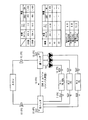
図1は、本実施形態における1次2次ポンプ方式の熱源制御システムの構成例を示す。 FIG. 1 shows a configuration example of a heat source control system of a primary secondary pump system in the present embodiment.
熱源制御システム100は、n台の冷凍機(熱源R1−Rn)10と、n台の1次冷水ポンプ11と、第1往ヘッダ12と、第2往ヘッダ13と、第1還ヘッダ14と、第2還ヘッダ15と、2次冷水ポンプ16と、空調負荷としての空調機(AHU)17と、PLC(Programmable Logic Controller)0およびPLC1とを備える。また、第1往ヘッダ12および第1還ヘッダ14は、バイパス管18を介して接続されている。なお、図1の例では、簡単のため空調機17を1台のみ示すが、実際には空調機17の台数及び種類は複数である。そして空調機17の近傍には図示しない比例2方弁などの制御弁が、空調機の熱交換器に1対1又は多対1で設置され、空調対象室の温度センサなどの信号から空調負荷に応じて2次側冷水流量を調整している。
The heat
冷凍機(熱源R)10は、例えば、ターボ冷凍機、インバータターボ冷凍機、吸収式冷凍機、冷温水発生機、スクリューチラー、ヒートポンプチラーなどである。熱源制御システム100に含まれるn台の冷凍機10は、個々の性能に相違がある場合があるが、本実施形態では、冷凍容量や運転の優先度などそれらの冷凍負荷に対する運転の基本的な対応は同一または同様である。また、各々の冷凍機10を制御する冷凍機側盤10aの入出力は、PLC0およびPLC1にそれぞれ接続されている。冷凍機側盤10aには、冷凍機の保護回路やそれに必要な補機のインターロック回路が納められている。なお、図1では、冷凍機側盤10aの図示は省略する。
The refrigerator (heat source R) 10 is, for example, a turbo refrigerator, an inverter turbo refrigerator, an absorption refrigerator, a cold / hot water generator, a screw chiller, a heat pump chiller, or the like. The
各々の冷凍機10は、それぞれ冷水1次往配管21により第1往ヘッダ12に対して並列に接続されており、それぞれ冷水1次還配管22により第1還ヘッダ14に対して並列に接続されている。冷水1次往配管21は、冷水の1次側において、冷凍機10で冷却された冷水を第1往ヘッダ12へ送水する配管である。また、冷水1次還配管22は、冷水の1次側において、空調機17で熱交換されて温度が上昇した冷水が合流した還冷水を、第1還ヘッダ14から冷凍機10まで送水する配管である。
Each
各冷凍機10に接続される各々の冷水1次往配管21には、冷凍機冷水出口温度Tcs1を計測する温度センサ23がそれぞれ設けられている。各々の温度センサ23で計測された冷凍機冷水出口温度Tcs1のPV(Process Value:計測値)は、PLC0およびPLC1にそれぞれ出力される。
Each cold water primary
各冷凍機10に接続される各々の冷水1次還配管22には、第1還ヘッダから冷凍機10に向かって、1次冷水ポンプ11と、1次冷水流量Vc1_Ri(iは冷凍機10の番号を示す)を計測する流量計24と、冷凍機冷水入口温度Tcr1を計測する温度センサ25とがそれぞれ設けられている。各々の温度センサ25で計測された冷凍機冷水入口温度Tcr1のPVは、PLC0およびPLC1にそれぞれ出力される。また、各々の流量計24で計測された1次冷水流量Vc1_RiのPVは、PLC0およびPLC1と、流量指示調節計(FIC)26とに出力される。また、1次冷水ポンプ11はポンプモータのインバータ(INV)27を備えている。流量指示調節計26は、複数の熱源に対して1台設けられており、後述するように、1次冷水流量Vc1_RiのPVとPLC0の指示(pVc1_SP)を受けて各々の1次冷水ポンプ11の流量(回転数)を制御する。1次冷水ポンプ11の回転数は、インバータ27が電源を周波数制御することで可変する。
In each of the chilled water
このように、図1に示す熱源制御システム100では、第1往ヘッダ12および第1還ヘッダ14と、第1往ヘッダ12および第1還ヘッダ14の間に並列に接続されたn台の冷凍機10と、これらの要素を接続する配管とによって、熱源の1次側が構成される。
As described above, in the heat
一方、図1に示す熱源制御システム100では、熱源の2次側において、第1往ヘッダ12の下流側には第2往ヘッダ13が接続され、第1還ヘッダ14の上流側には第2還ヘッダ15が接続されている。また、第1往ヘッダ12と第2往ヘッダ13とは、それぞれに2次冷水ポンプ16が配置された複数の配管31で接続されている。なお、各々の2次冷水ポンプ16の回転数は、インバータ32が電源を周波数制御することで可変する。
On the other hand, in the heat
この2次冷水ポンプ16の回転数可変は、2次側に位置する全空調機の要求冷水量の総量に応じて行なわれるのだが、例えば2次側冷水配管系の何れかの位置に設置される圧力計のPVに応じて制御され、各空調機17の制御弁により空調負荷に応じて熱交換器へ流入する冷水量が絞られた場合、2次冷水ポンプ16の回転数がそのままだと圧力計のPV値が上昇し、設定圧との偏差に応じて2次冷水ポンプ16の回転数を低下させる制御を行なう。尚、2次側の変流量制御の一例として圧力による例を示したが、これに限定されることなく流量によっても熱量によっても良く、どのような2次側の変流量制御でも良い。
The rotation speed of the secondary
また、第2往ヘッダ13には、2次冷水往温度Tcs2を計測する温度センサ33が設けられる。温度センサ33で計測された2次冷水往温度Tcs2のPVは、PLC0およびPLC1に出力される。また、第1還ヘッダ14には、2次冷水還温度Tcr2を計測する温度センサ34が設けられる。温度センサ34で計測された2次冷水還温度Tcr2のPVは、PLC0およびPLC1に出力される。さらに、第2還ヘッダ15と第1還ヘッダ14との間には、2次冷水流量Vc2を計測する流量計35が設けられる。流量計35で計測された2次冷水流量Vc2のPVは、PLC0およびPLC1に出力される。
Further, the second forward header 13 is provided with a temperature sensor 33 for measuring the secondary cold water forward temperature Tcs2. The PV of the secondary cold water temperature Tcs2 measured by the temperature sensor 33 is output to PLC0 and PLC1. The
そして、第2往ヘッダ13と第2還ヘッダ15との間には、第2往ヘッダ13と空調機17とを接続する冷水2次往配管36と、空調機17と第2還ヘッダ15とを接続する冷水2次還配管37とが設けられており、これらの配管によって第2往ヘッダ13および第2還ヘッダ15が空調機17と接続される。冷水2次往配管36は、冷水の2次側において、冷凍機10で冷却された冷水を第2往ヘッダ13から空調機17に送水する配管である。冷水2次還配管37は、冷水の2次側において、空調機17で熱交換されて温度が上昇した冷水を空調機17から第2還ヘッダ15に送水する配管である。
Between the second forward header 13 and the
このように、図1に示す熱源制御システム100では、第1往ヘッダ12および第2往ヘッダ13と、第1還ヘッダ14および第2還ヘッダ15と、空調機17と、これらの要素を接続する配管によって2次側が構成される。
As described above, in the heat
PLC0およびPLC1は、熱源制御システム100の制御を分担して実行するコントローラである。PLC0およびPLC1は、例えば空調設備が設置されている建物の中央監視装置とそれぞれ接続され、中央監視装置からの指示を受ける。なお、図1では中央監視装置の図示は省略している。
PLC0 and PLC1 are controllers that share and execute control of the heat
なお、図2は、熱源制御システム100における中央監視装置、PLC0、PLC1および冷凍機nとの入出力の例を示す図である。図2では、n台の冷凍機10のうち1台分の冷凍機nのみを示し、PLC0、PLC1と他の冷凍機との接続はいずれも同一または同様であるので重複説明は省略する。また、図2では、PLC0、PLC1に対する温度センサ23,25,33,34および流量計24,35との接続はいずれも図示を省略している。
FIG. 2 is a diagram illustrating an example of input / output with the central monitoring device, PLC0, PLC1, and refrigerator n in the heat
PLC0は、制御装置の一例であって、1次側の冷凍機冷水出口温度および1次冷水流量を制御する。なお、PLC0は、PLC1と同時に設置されるものでもよく、PLC1を有する既存の熱源制御システムに後付けで設置されるものであってもよい。 The PLC0 is an example of a control device, and controls the primary-side refrigerator cold water outlet temperature and the primary cold water flow rate. Note that PLC0 may be installed at the same time as PLC1, or may be installed later in an existing heat source control system having PLC1.
例えば、図2に示すように、PLC0は、制御目標値である2次冷水往温度の設定値Tcs2_SP(SP:Set Point)を中央監視装置から受ける。また、PLC0は、冷凍機側盤10aに冷凍機冷水出口温度の設定値Tcs1_SPを出力し、冷凍機側盤10aからその冷凍機nの運転状態(オン/オフ)を示す信号を受ける。PLC0は、各々の冷凍機側盤10aから受けた運転状態の信号によりシステム全体での冷凍機10の運転台数Nの情報を取得できる。また、PLC0は、1次冷水流量比率の設定値pVc1_SPを流量指示調節計26に出力する。
For example, as illustrated in FIG. 2, the
ここで、図2に示すように、流量指示調節計26は、PLC0からpVc1_SPを受け、流量計24から1次冷水流量Vc1_RiのPVを受ける。また、流量指示調節計26は、1次冷水ポンプ11のインバータ27にインバータ制御用の流量信号を出力する。そして、1次冷水ポンプ11のインバータ27は、流量指示調節計26から受けた流量信号に応じて1次冷水ポンプ11の電源の周波数制御を行い、1次冷水ポンプ11の回転数を可変させる。これにより、1次冷水ポンプ11による1次冷水流量を調節することができる。なお、1次冷水ポンプ11のインバータ27は冷凍機側盤10aと接続されており、1次冷水ポンプ11のオン/オフは冷凍機10の運転状態と連動するように制御される。
Here, as shown in FIG. 2, the flow
PLC1は、システム全体での冷凍機10の稼働台数を変更する制御(熱源台数制御)を実行する。例えば、図2に示すように、PLC1は、熱源群発停指令(システム全体での熱源のオン/オフ)を中央監視装置から受ける。また、PLC1は、冷凍機側盤10aに発停指令(個々の熱源のオン/オフ)を出力し、冷凍機側盤10aからはその冷凍機nの運転状態(オン/オフ)を示す信号を受ける。
The
次に、本実施形態の熱源制御システムの制御例を説明する。 Next, a control example of the heat source control system of the present embodiment will be described.
図3は、熱源制御システム全体の動作を示す流れ図である。図3の処理は、中央監視装置から熱源群の起動指令(システム全体での熱源のオン)が出力されたときに開始される。 FIG. 3 is a flowchart showing the operation of the entire heat source control system. The process in FIG. 3 is started when a heat source group start command (heat source on in the entire system) is output from the central monitoring device.
ステップS100において、PLC1は、熱源群を起動する。ステップS101において、PLC0およびPLC1は、例えばPLC内に設けられたメモリ等から各機器の設計値(各種パラメータの上限値および下限値など)の情報を取得する。ステップS102において、PLC1は熱源群のベース機を起動させる。
In step S100, the
そして、ステップS103において、PLC0およびPLC1は、熱源制御システム100の定周期ループ制御を行う。例えば、中央監視装置から熱源群の停止指令を受けるまでこれらの制御は継続して行われる。
In step S <b> 103, the PLC <b> 0 and the PLC <b> 1 perform the periodic loop control of the heat
ステップS103でのPLC0は1次側の冷凍機冷水出口温度および1次冷水流量の制御を実行する。ステップS103でのPLC0の制御の例は図4に示す。同様に、ステップS103でのPLC1は熱源台数制御を実行する。なお、以下の熱源台数制御の説明では、冷凍機を追加で起動させることを増段と称し、冷凍機を停止させることを減段と称する。 The PLC0 in step S103 executes control of the primary side refrigerator cold water outlet temperature and the primary cold water flow rate. An example of PLC0 control in step S103 is shown in FIG. Similarly, PLC1 in step S103 performs heat source number control. In the following description of the control of the number of heat sources, starting the additional refrigerator is referred to as “increase”, and stopping the refrigerator is referred to as “increase”.
ここで、本実施形態におけるPLC1の熱源台数制御は、公知の制御と同様であってもよいが、2次負荷熱量による増段判定と減段判定に加えて、2次冷水往温度Tcs2と2次冷水還温度Tcr2が2次冷水往温度の設定値Tcs2_SPに追従するようにPLC1が熱源台数制御を行うことが好ましい。この場合、例えば、PLC1は、2次冷水往温度の設定値Tcs2_SPに調整パラメータ(例えば1〜2℃程度)の値を足した増段判定温度(2次側冷水往温度に基づく冷凍能力不足判定)よりも2次冷水往温度Tcs2が高いときに熱源を1台分増段し、2次冷水往温度の設定値Tcs2_SPに調整パラメータ(例えば0.5℃〜2℃程度)の値を足した減段判定温度(2次側冷水還温度と2次側冷水往温度との差分に基づく冷凍能力過分判定)よりも2次冷水還温度Tcr2が低いときに熱源を1台分減段する。なお、PLC1の熱源台数制御を公知の制御と同様にすると、例えば、既存の熱源制御システムにPLC0を後付けで設置して本実施形態の熱源制御システム100を実現する場合には、PLC1の熱源台数制御のアルゴリズムを既存のものから変更しなくてすむのでシステムの導入が容易となるという利点がある。
Here, the control of the number of heat sources of the
図4は、図3のステップS103におけるPLC0の制御例を示す流れ図である。なお、以下の制御例の説明では、熱源制御システム100の熱源構成において、各熱源の(冷凍機出口温度、冷水流量、定格に対する冷水流量比率、バイパス流量などの)上限値および下限値はいずれも同じであり、各熱源において、冷凍機冷水出口温度の設定値Tcs1_SPと1次冷水流量比率の設定値pVc1_SPとがいずれも同じに設定される(すなわち均等容量方式)ことを前提として説明を行う。
FIG. 4 is a flowchart showing a control example of the PLC0 in step S103 of FIG. In the description of the control examples below, in the heat source configuration of the heat
ステップS200において、PLC0は、制御目標値である2次冷水往温度の設定値Tcs2_SPを中央監視装置から受ける。なお、2次冷水往温度の設定値Tcs2_SPは、例えば、中央監視装置が実行するスケジュール管理処理によって日付に応じて自動的に決定されてもよく、中央監視装置を操作する設備管理者が手動で設定してもよい。また、PLC0に対して制御目標値である2次冷水往温度の設定値Tcs2_SPを送信する装置は、中央監視装置以外の他の装置類であってもよい。 In step S200, the PLC0 receives the set value Tcs2_SP of the secondary cold water temperature that is the control target value from the central monitoring device. Note that the set value Tcs2_SP of the secondary cold water temperature may be automatically determined according to the date by a schedule management process executed by the central monitoring device, for example, by a facility administrator who operates the central monitoring device manually. It may be set. Further, the device that transmits the set value Tcs2_SP of the secondary chilled water temperature that is the control target value to the PLC0 may be other devices other than the central monitoring device.
ステップS201において、PLC0は、温度センサ23,25,33,34から冷凍機冷水出口温度Tcs1、冷凍機冷水入口温度Tcr1、2次冷水往温度Tcs2、2次冷水還温度Tcr2のPVをそれぞれ取得する。また、PLC0は、流量計24,35から1次冷水流量Vc1_Ri、2次冷水流量Vc2のPVをそれぞれ取得する。また、PLC0は、各々の冷凍機側盤10aから受けた運転状態の信号によりシステム全体での冷凍機10の運転台数Nの情報を取得する。
In step S201, the PLC0 obtains the PV of the refrigerator cold water outlet temperature Tcs1, the refrigerator cold water inlet temperature Tcr1, the secondary cold water feed temperature Tcs2, and the secondary cold water return temperature Tcr2 from the
ステップS202において、PLC0は、2次冷水往温度Tcs2、2次冷水還温度Tcr2および2次冷水流量Vc2の各PVを用いて、以下の式(1)により2次負荷熱量Q2を算出する。ここで、「k」は水の比熱の物理定数および水の密度の物理定数をまとめて示した係数である。
Q2=(Tcr2−Tcs2)×Vc2×k[kW] …(1)
ステップS203において、PLC0は、冷凍機10の運転台数Nに基づいて、N台運転時における1次冷水流量の上限値Vc1_MAXを以下の式(2)により算出し、N台運転時における1次冷水流量の下限値Vc1_MINを以下の式(3)により算出する。また、PLC0は、N台運転時における1次生成熱量の最大値Q1_MAXを以下の式(4)により算出する。
Vc1_MAX=Vc1_MAX_Ri×N[m3/h] …(2)
Vc1_MIN=Vc1_MAX×pVc1_MIN_Ri[m3/h] …(3)
Q1_MAX=Q1_MAX_Ri×N[kW] …(4)
ここで、「Vc1_MAX_Ri」は、番号iの冷凍機10における1次冷水流量の上限値である。「pVc1_MIN_Ri」は、番号iの冷凍機10における1次冷水流量比率の下限値である。「Q1_MAX_Ri」は、番号iの冷凍機10における定格生成熱量である。これらのパラメータは、図3のステップS100の処理で取得される。
In step S202, PLC0 calculates secondary load heat quantity Q2 by the following formula (1) using each PV of secondary cold water going temperature Tcs2, secondary cold water return temperature Tcr2, and secondary cold water flow rate Vc2. Here, “k” is a coefficient collectively showing the physical constant of the specific heat of water and the physical constant of the density of water.
Q2 = (Tcr2−Tcs2) × Vc2 × k [kW] (1)
In step S203, the
Vc1_MAX = Vc1_MAX_Ri × N [m 3 / h] (2)
Vc1_MIN = Vc1_MAX × pVc1_MIN_Ri [m 3 / h] (3)
Q1_MAX = Q1_MAX_Ri × N [kW] (4)
Here, “Vc1_MAX_Ri” is the upper limit value of the primary chilled water flow rate in the
なお、1次冷水流量については、冷凍機の蒸発器チューブ内流速が速すぎると圧力損失が増加するだけでなく、チューブ内にエロージョンを発生させる原因となるので冷凍機メーカにより上限値が設定されている。1次冷水流量比率は、逆に蒸発器チューブ内の流速が遅すぎる場合、伝熱の低下と流水中の異物沈降による腐食を起こす虞があるため冷凍機メーカによりチューブ内流速に応じて冷水流量の定格値の比率として下限値が設定されている。 Regarding the primary chilled water flow rate, if the flow velocity in the evaporator tube of the refrigerator is too high, not only will pressure loss increase, but it will also cause erosion in the tube, so an upper limit is set by the refrigerator manufacturer. ing. On the other hand, if the flow rate in the evaporator tube is too slow, the primary chilled water flow rate ratio may cause corrosion due to reduced heat transfer and sedimentation of foreign matter in the running water. The lower limit is set as the ratio of the rated values.
ステップS204において、PLC0は、2次負荷熱量Q2と1次生成熱量の最大値Q1_MAXとを用いて、以下の式(5)により熱源負荷率pQ1を算出する。
pQ1=Q2/Q1_MAX×100[%] …(5)
ステップS205において、PLC0は、2次負荷熱量Q2に対して冷凍機の運転台数Nが適切かを判定する。具体的には、PLC0は、熱源負荷率pQ1が番号iの冷凍機10における生成熱量比率の下限値(pQ1_MIN_Ri)以上であり、かつ熱源負荷率pQ1が熱源負荷率pQ1の最大値(pQ1_MAX)以下であるか(pQ1_MIN_Ri≦pQ1≦pQ1_MAX)を判定する。ここで、pQ1_MAX=100[%]であり、pQ1_MIN_Riは設計値で決定される。
In step S204, PLC0 calculates heat source load factor pQ1 by the following formula | equation (5) using secondary load calorie | heat amount Q2 and maximum value Q1_MAX of primary production | generation calorie | heat amount.
pQ1 = Q2 / Q1_MAX × 100 [%] (5)
In step S205, the
pQ1_MIN_Ri≦pQ1≦pQ1_MAXの場合、2次負荷熱量Q2に対して現在の冷凍機10の運転台数Nが適切な状態であり、ステップS206に処理が移行する。一方、pQ1_MIN_Ri≦pQ1≦pQ1_MAXではない場合、2次負荷熱量Q2に対して現在の冷凍機10の運転台数Nが適切ではない状態であり、ステップS210に処理が移行する。
In the case of pQ1_MIN_Ri ≦ pQ1 ≦ pQ1_MAX, the current operating number N of the
ステップS206において、PLC0は、2次冷水往温度Tcs2、2次冷水還温度Tcr2を用いて、以下の式(6)により空調負荷の出口と入口との間の2次冷水温度差ΔT2を算出する。
ΔT2=Tcr2−Tcs2[℃] …(6)
ステップS207において、PLC0は、2次冷水温度差ΔT2が十分に取れているかを判定する。具体的には、PLC0は、2次冷水温度差ΔT2が2次冷水温度差の設計値(ΔT2_DV=5℃)以上か否かを判定する。2次冷水温度差ΔT2が2次冷水温度差の設計値以上である場合(ΔT2≧ΔT2_DV)には、ステップS208に処理が移行する。一方、2次冷水温度差ΔT2が2次冷水温度差の設計値未満である場合(ΔT2<ΔT2_DV)には、ステップS209に処理が移行する。
In step S206, the
ΔT2 = Tcr2−Tcs2 [° C.] (6)
In step S207, PLC0 determines whether the secondary chilled water temperature difference ΔT2 is sufficiently obtained. Specifically, the
ステップS208において、2次冷水温度差ΔT2が2次冷水温度差の設計値以上であって2次冷水温度差ΔT2が十分に取れているので、PLC0は、1次冷水流量=2次冷水流量、1次冷水冷凍機出口温度=2次冷水往温度となるように制御を行う。 In step S208, since the secondary chilled water temperature difference ΔT2 is equal to or greater than the design value of the secondary chilled water temperature difference and the secondary chilled water temperature difference ΔT2 is sufficiently large, the PLC0 has a primary chilled water flow rate = secondary chilled water flow rate, Control is performed so that the outlet temperature of the primary chilled water refrigerator is equal to the temperature of the secondary chilled water.
具体的には、PLC0は、第1の制御設定値である冷凍機冷水出口温度の設定値Tcs1_SPを、2次冷水往温度の設定値Tcs2_SPと等しくする(Tcs1_SP=Tsc2_SP)。また、PLC0は、第2の制御設定値である1次冷水流量比率の設定値pVc1_SPを、以下の式(7)で算出する。ステップS208の後、PLC0は図4の処理を終了する。
pVc1_SP=Vc2/Vc1_MAX×100[%] …(7)
ステップS209において、PLC0は、2次負荷熱量Q2と1次側の生成熱量Q1とが等しくなる条件(Q2=Q1)で、各種の設計条件を満たして冷凍機10が安全運転できるような第1の制御設定値(Tcs1_SP)および第2の制御設定値(pVc1_SP)の解を算出する。ステップS209の処理の例は図5に示す。
Specifically, the
pVc1_SP = Vc2 / Vc1_MAX × 100 [%] (7)
In step S209, the PLC0 performs the first operation so that the
ここで、ステップS209では、1次冷水ポンプ11が送水する1次冷水と、バイパス管18を介して還ヘッダから第1往ヘッダ12へ流入する2次還冷水とが合流した2次冷水往温度が制御目標値である2次冷水往温度の設定値となるように、PLC0は、2次冷水往温度の設定値Tcs2_SPと、2次冷水還温度Tcr2と、2次冷水流量Vc2を用いて、第1の制御設定値(Tcs1_SP)および第2の制御設定値(pVc1_SP)を算出する。この演算においては、仮の冷凍機冷水出口温度tTcs1または仮の1次冷水流量tVc1を代入することで、これらの仮の値に対応する解を算出することができる。ステップS209の後、PLC0は図4の処理を終了する。
Here, in step S209, the secondary cold water flow temperature where the primary cold water sent by the primary
ここで、ステップS209の制御では、2次冷水還温度Tcr2は冷凍機冷水出口温度Tcs1よりも高い温度である。つまり、ステップS209でのPLC0は、第1の制御設定値および第2の制御設定値に基づいて送水される1次冷水の冷凍機冷水出口温度を2次冷水往温度の設定値よりも低い温度もしくは同じ温度とする。そして、PLC0は、冷凍機10から送水される1次冷水とバイパス管18から逆流する2次還冷水とをミキシングした2次冷水往温度Tcs2が所望の2次冷水往温度の設定値Tcs2_SPとなるように制御を行う(なお、第1の制御設定値および第2の制御設定値の値によっては1次冷水流量=2次冷水流量となってミキシングをさせない場合もある)。そのため、2次冷水往温度の設定値Tcs2_SPは、冷凍機冷水出口温度の下限値Tcs1_MINよりも高い温度に設定することが好ましい。なお、本実施形態による制御は、2次冷水往温度の設定値Tcs2_SPを高く設定しても影響のない冬期や中間期の運転に適している。
Here, in the control of step S209, the secondary cold water return temperature Tcr2 is higher than the refrigerator cold water outlet temperature Tcs1. That is, PLC0 in step S209 is a temperature at which the chiller outlet temperature of the primary chilled water fed based on the first control set value and the second control set value is lower than the set value of the secondary chilled water feed temperature. Or the same temperature. In the
ステップS210において、PLC0は、冷凍機10の運転台数Nが不足しているかを判定する。具体的には、PLC0は、熱源負荷率pQ1が熱源負荷率の最大値pQ1_MAXより大きいか(pQ1>pQ1_MAX)を判定する。熱源負荷率pQ1が熱源負荷率の最大値pQ1_MAXより大きい場合、冷凍機10の運転台数Nが不足している状態であり、ステップS211に処理が移行する。一方、熱源負荷率pQ1が熱源負荷率の最大値pQ1_MAX以下である場合、冷凍機10の運転台数Nが過剰な状態であり、ステップS212に処理が移行する。
In step S210, the
ステップS211において、2次負荷熱量Q2に対して冷凍機10の運転台数が不足しているため、PLC0は、現在の冷凍機10の運転台数Nの条件下で1次側の生成熱量Q1が最大となるように制御を行う。具体的には、PLC0は、第1の制御設定値である冷凍機冷水出口温度の設定値Tcs1_SPを、冷凍機冷水出口温度の下限値Tcs1_MINまで下げる(Tcs1_SP=Tsc1_MIN)。また、PLC0は、第2の制御設定値である1次冷水流量比率の設定値pVc1_SPを最大の100%とする(pVc1_SP=100[%])。ステップS211の後、PLC0は図4の処理を終了する。
In step S211, because the number of operating
ステップS212において、2次負荷熱量Q2に対しての冷凍機10の運転台数Nが過剰であるため、PLC0は、1次側の生成熱量を制御範囲内で最小とするための1次冷水流量の判定を行う。具体的には、PLC0は、1次冷水流量Vc1が最小となるときにバイパス管流量が上限値を超えないかを判定する。具体的には、PLC0は、2次冷水流量Vc2から1次冷水流量の下限値Vc1_MINを減じた値がバイパス管流量の上限値Vbp_MAXより大きいか(Vbp_MAX<Vc2−Vc1_MIN)を判定する。1次冷水流量Vc1が最小となるときにバイパス管流量が上限値を超える場合、ステップS213に処理が移行する。1次冷水流量Vc1が最小となるときにバイパス管流量が上限値を超えない場合、ステップS214に処理が移行する。
In step S212, since the number of operating units N of the
ステップS213において、PLC0は、現在の冷凍機10の運転台数Nの条件下で1次側の生成熱量Q1が可能な限り小さくなるように制御を行う。具体的には、PLC0は、第1の制御設定値である冷凍機冷水出口温度の設定値Tcs1_SPを、冷凍機冷水出口温度の下限値Tcs1_MINとする(Tcs1_SP=Tsc1_MIN)。また、PLC0は、第2の制御設定値である1次冷水流量比率の設定値pVc1_SPを以下の式(8)で算出する。ステップS213の後、PLC0は図4の処理を終了する。
pVc1_SP=(Vc2−Vbp_MAX)/Vc1_MAX×100[%] …(8)
ステップS214において、PLC0は、現在の冷凍機10の運転台数Nの条件下で1次側の生成熱量Q1が可能な限り小さくなるように制御を行う。具体的には、PLC0は、第1の制御設定値である冷凍機冷水出口温度の設定値Tcs1_SPを、冷凍機冷水出口温度の下限値Tcs1_MINとする(Tcs1_SP=Tsc1_MIN)。また、PLC0は、第2の制御設定値である1次冷水流量比率の設定値pVc1_SPを、個々の冷凍機10での1次冷水流量比率の下限値pVc1_MIN_Riとする(pVc1_SP=pVc1_MIN_Ri)。ステップS214の後、PLC0は図4の処理を終了する。
In step S213, the
pVc1_SP = (Vc2−Vbp_MAX) / Vc1_MAX × 100 [%] (8)
In step S214, the
次に、図5、図6を参照しつつ、図4のステップS209での処理を詳細に説明する。図5は、図4のステップS209におけるPLC0の処理例を示す流れ図である。 Next, the process in step S209 of FIG. 4 will be described in detail with reference to FIGS. FIG. 5 is a flowchart showing a processing example of PLC0 in step S209 of FIG.
また、図6は、Q1=Q2のときの1次冷水流量Vc1を定格値100%とした比率と1次冷水温度差ΔT1との関係の例を示す図である。図6の縦軸は1次冷水温度差ΔT1を示し、図6の横軸は1次冷水流量Vc1を定格値100%とした比率を示す。また、図6の曲線は、Q1=Q2=Constのときの1次冷水流量Vc1と1次冷水温度差ΔT1との関係をプロットしたものである。図6のQ1=Q2の曲線で示される熱量の定格比率は45%で、横軸100%のとき縦軸は45%、横軸67%のとき縦軸は67%、横軸50%のとき縦軸は90%、縦軸120%のとき横軸37.5%である。なお、図6に示す曲線はあくまで一例であり、Q2が増減することで曲線がシフトする。 FIG. 6 is a diagram showing an example of the relationship between the ratio of the primary chilled water flow rate Vc1 when Q1 = Q2 to the rated value of 100% and the primary chilled water temperature difference ΔT1. The vertical axis in FIG. 6 represents the primary chilled water temperature difference ΔT1, and the horizontal axis in FIG. 6 represents the ratio with the primary chilled water flow rate Vc1 as the rated value of 100%. Further, the curve of FIG. 6 is a plot of the relationship between the primary chilled water flow rate Vc1 and the primary chilled water temperature difference ΔT1 when Q1 = Q2 = Const. The rated ratio of heat quantity shown by the curve of Q1 = Q2 in FIG. 6 is 45%. When the horizontal axis is 100%, the vertical axis is 45%, when the horizontal axis is 67%, the vertical axis is 67%, and the horizontal axis is 50%. When the vertical axis is 90% and the vertical axis is 120%, the horizontal axis is 37.5%. The curve shown in FIG. 6 is merely an example, and the curve shifts as Q2 increases or decreases.
ここで、図5に示すステップS300番台の制御では、計測値から算出した2次側の負荷熱量Q2と計算で求める1次側の生成熱量Q1とが等しくなる条件で、かつ冷凍機10の出口と入口との間の1次冷水温度差ΔT1を制御範囲内で最大とすることで軽負荷運転による冷凍機コンプレッサの停止を抑制するとともに、1次冷水ポンプ11の流量を制御範囲内で極力小さく制御することで1次冷水搬送動力の削減が期待できる順に、第1の制御設定値(Tcs1_SP)および第2の制御設定値(pVc1_SP)の解を求める。
Here, in the control in the step S300 range shown in FIG. 5, the secondary load heat amount Q2 calculated from the measured value is equal to the primary generated heat amount Q1 obtained by calculation, and the outlet of the
ステップS300において、PLC0は、冷凍機冷水出口温度が下限値のとき(図6の点(a))の解を算出する。具体的には、PLC0は、以下の式(9)において、仮の冷凍機冷水出口温度tTcs1に冷凍機冷水出口温度の下限値Tcs1_MINを代入したときの仮の1次冷水流量tVc1を算出する。
In step S300, the
![]()
![]()
また、PLC0は、仮の1次冷水流量tVc1に基づく仮のバイパス管流量tVbpを以下の式(10)で算出する。
tVbp=Vc2−tVc1 ……(10)
ステップS301において、PLC0は、ステップS300で算出した解が設計条件を満たすかを判定する。具体的には、PLC0は、以下の(条件1)および(条件2)を満たす場合に設計条件を満たすと判定する。
(条件1):仮の1次冷水流量tVc1が1次冷水流量の下限値から上限値までの範囲内(Vc1_MIN≦tVc1≦Vc1_MAX)にある。
(条件2):仮のバイパス管流量tVbpがバイパス管流量の上限値Vbp_MAX以下(tVbp≦Vbp_MAX)である。
Further, the
tVbp = Vc2−tVc1 (10)
In step S301, the
(Condition 1): The temporary primary chilled water flow rate tVc1 is within the range from the lower limit value to the upper limit value of the primary chilled water flow rate (Vc1_MIN ≦ tVc1 ≦ Vc1_MAX).
(Condition 2): The temporary bypass pipe flow rate tVbp is equal to or lower than the upper limit value Vbp_MAX (tVbp ≦ Vbp_MAX) of the bypass pipe flow rate.
上記の設計条件を満たす場合にはステップS308に処理が移行する。一方、上記の設計条件を満たさない場合にはステップS302に処理が移行する。 If the above design condition is satisfied, the process proceeds to step S308. On the other hand, if the above design conditions are not satisfied, the process proceeds to step S302.
ステップS302において、PLC0は、1次冷水流量が下限値のとき(図6の点(b))の解を算出する。具体的には、PLC0は、以下の式(11)において、仮の1次冷水流量tVc1に1次冷水流量の下限値Vc1_MINを代入したときの仮の冷凍機冷水出口温度tTcs1を算出する。 In step S302, PLC0 calculates a solution when the primary chilled water flow rate is the lower limit (point (b) in FIG. 6). Specifically, PLC0 calculates a temporary refrigerator cold water outlet temperature tTcs1 when the lower limit value Vc1_MIN of the primary cold water flow rate is substituted into the temporary primary cold water flow rate tVc1 in the following equation (11).
![]()
![]()
また、PLC0は、仮の冷凍機冷水出口温度tTcs1に基づく仮の1次冷水温度差tΔT1を以下の式(12)で算出する。
tΔT1=Tcr2−tTcs1 ……(12)
ステップS303において、PLC0は、ステップS302で算出した解が設計条件を満たすかを判定する。具体的には、PLC0は、以下の(条件11)〜(条件13)の全てを満たす場合に設計条件を満たすと判定する。
(条件11):仮の冷凍機冷水出口温度tTcs1が冷凍機冷水出口温度の下限値から上限値までの範囲内(Tcs1_MIN≦tTcs1≦Tcs1_MAX)にある。
(条件12):仮の1次冷水温度差tΔT1が1次冷水温度差の下限値ΔT1_MIN以上(tΔT1≧ΔT1_MIN)である。
(条件13):仮のバイパス管流量tVbpがバイパス管流量の上限値Vbp_MAX以下(tVbp≦Vbp_MAX)である。
Moreover, PLC0 calculates the temporary primary cold water temperature difference t (DELTA) T1 based on temporary refrigerator cold water outlet temperature tTcs1 by the following formula | equation (12).
tΔT1 = Tcr2−tTcs1 (12)
In step S303, PLC0 determines whether the solution calculated in step S302 satisfies the design condition. Specifically, PLC0 determines that the design condition is satisfied when all of the following (condition 11) to (condition 13) are satisfied.
(Condition 11): Temporary refrigerator cold water outlet temperature tTcs1 is within the range from the lower limit value to the upper limit value of the refrigerator cold water outlet temperature (Tcs1_MIN ≦ tTcs1 ≦ Tcs1_MAX).
(Condition 12): Temporary primary cold water temperature difference tΔT1 is equal to or greater than the lower limit value ΔT1_MIN of the primary cold water temperature difference (tΔT1 ≧ ΔT1_MIN).
(Condition 13): The temporary bypass pipe flow rate tVbp is equal to or lower than the upper limit value Vbp_MAX (tVbp ≦ Vbp_MAX) of the bypass pipe flow rate.
上記の設計条件を満たす場合にはステップS308に処理が移行する。一方、上記の設計条件を満たさない場合にはステップS304に処理が移行する。 If the above design condition is satisfied, the process proceeds to step S308. On the other hand, if the above design condition is not satisfied, the process proceeds to step S304.
ステップS304において、PLC0は、1次冷水流量がバイパス管流量の上限値のとき(図6の点(c))の解を算出する。具体的には、PLC0は、上記の式(11)において、仮の1次冷水流量tVc1にVc2−Vbp_MAXを代入したときの仮の冷凍機冷水出口温度tTcs1を算出する。また、PLC0は、上記の式(12)により、1次冷水流量がバイパス管流量の上限値のときの仮の1次冷水温度差tΔT1を算出する。 In step S304, PLC0 calculates a solution when the primary chilled water flow rate is the upper limit value of the bypass pipe flow rate (point (c) in FIG. 6). Specifically, PLC0 calculates the temporary refrigerator cold water outlet temperature tTcs1 when Vc2-Vbp_MAX is substituted into the temporary primary cold water flow rate tVc1 in the above equation (11). Further, PLC0 calculates a temporary primary chilled water temperature difference tΔT1 when the primary chilled water flow rate is the upper limit value of the bypass pipe flow rate according to the above equation (12).
なお、図6(c)に示すバイパス管流量の上限値のときの仮の1次冷水流量tVc1は、現在の熱源台数Nに応じて変動する。ここで、バイパス管流量の上限値Vbp_MAXは固定値(一般的に冷凍機1台分の流量)であるが、1次冷水流量は熱源台数Nが多いほど大きくなり、熱源台数Nが少なくなれば小さくなる。したがって、熱源台数Nが多いほどバイパス管流量の上限値のときの仮の1次冷水流量tVc1は相対的に高い値となり、図6での点(c)の位置が1次冷水流量の上限値の方向に近づく。逆に、熱源台数Nが少ないほどバイパス管流量の上限値のときの仮の1次冷水流量tVc1は相対的に低い値となり、図6での点(c)の位置が1次冷水流量の下限値の方向に近づく。 The temporary primary chilled water flow rate tVc1 at the upper limit value of the bypass pipe flow rate shown in FIG. 6C varies according to the current number N of heat sources. Here, the upper limit value Vbp_MAX of the bypass pipe flow rate is a fixed value (generally, the flow rate for one refrigerator), but the primary chilled water flow rate increases as the number N of heat sources increases, and the number N of heat sources decreases. Get smaller. Therefore, as the number N of heat sources increases, the temporary primary chilled water flow tVc1 at the upper limit of the bypass pipe flow becomes a relatively high value, and the position of the point (c) in FIG. 6 is the upper limit of the primary chilled water flow. Approach the direction. Conversely, as the number N of heat sources is smaller, the temporary primary chilled water flow rate tVc1 at the upper limit value of the bypass pipe flow rate becomes a relatively low value, and the position of the point (c) in FIG. 6 is the lower limit of the primary chilled water flow rate. Approach the value direction.
ステップS305において、PLC0は、ステップS304で算出した解が設計条件を満たすかを判定する。具体的には、PLC0は、PLC0は、以下の(条件21)〜(条件23)の全てを満たす場合に設計条件を満たすと判定する。
(条件21):仮の冷凍機冷水出口温度tTcs1が冷凍機冷水出口温度の下限値から上限値までの範囲内(Tcs1_MIN≦tTcs1≦Tcs1_MAX)にある。
(条件22):仮の1次冷水温度差tΔT1が1次冷水温度差の下限値ΔT1_MIN以上(tΔT1≧ΔT1_MIN)である。
(条件23):仮の1次冷水流量tVc1が1次冷水流量の下限値から上限値までの範囲内(Vc1_MIN≦tVc1≦Vc1_MAX)にある。
In step S305, the
(Condition 21): The temporary refrigerator cold water outlet temperature tTcs1 is within the range from the lower limit value to the upper limit value of the refrigerator cold water outlet temperature (Tcs1_MIN ≦ tTcs1 ≦ Tcs1_MAX).
(Condition 22): Temporary primary cold water temperature difference tΔT1 is equal to or greater than the lower limit value ΔT1_MIN of the primary cold water temperature difference (tΔT1 ≧ ΔT1_MIN).
(Condition 23): The temporary primary chilled water flow rate tVc1 is within the range from the lower limit value to the upper limit value of the primary chilled water flow rate (Vc1_MIN ≦ tVc1 ≦ Vc1_MAX).
上記の設計条件を満たす場合にはステップS308に処理が移行する。一方、上記の設計条件を満たさない場合には、逆流が発生する解の組み合わせでは設計条件を満たすことが出来ないと考えられる。したがって、計測値から算出した2次側の負荷熱量Q2と計算で求める1次側の生成熱量Q1とが等しくなる条件で、かつ冷凍機10の出口と入口との間の1次冷水温度差ΔT1が最大となる解はtTcs1=Tcs2_SP、tVc1=Vc2の1次冷水と2次冷水が均衡した状態となる。Vc2が1次冷水ポンプ11の流量調整範囲内(Vc2≦Vc1_MAX)であるかを判定するために、ステップS306に処理が移行する。
If the above design condition is satisfied, the process proceeds to step S308. On the other hand, when the above design condition is not satisfied, it is considered that the design condition cannot be satisfied by a combination of solutions in which backflow occurs. Therefore, the primary chilled water temperature difference ΔT1 between the outlet and the inlet of the
ステップS306において、PLC0は、2次冷水流量Vc2がその時点における冷凍機の運転台数から算出した1次冷水流量の上限値Vc1_MAX以下であるか(Vc2≦Vc1_MAX)を判定する。2次冷水流量Vc2が1次冷水流量の上限値Vc1_MAX以下である場合にはステップS307に処理が移行する。一方、2次冷水流量Vc2が1次冷水流量の上限値Vc1_MAXよりも大きい場合には、設計条件を満たす解が存在しないため、ステップS309に処理が移行する。
In step S306, the
ステップS307において、1次冷水流量と2次冷水流量とが等しいときの解を算出する。PLC0は、仮の1次冷水流量tVc1を2次冷水流量Vc2とし(tVc1=Vc2)、仮の冷凍機冷水出口温度tTcs1を2次冷水往温度の設定値Tcs2_SPとする(tTcs1=Tcs2_SP)。その後、ステップS308に処理が移行する。 In step S307, a solution when the primary cold water flow rate and the secondary cold water flow rate are equal is calculated. The PLC0 sets the temporary primary chilled water flow rate tVc1 as the secondary chilled water flow rate Vc2 (tVc1 = Vc2), and sets the temporary chiller cold water outlet temperature tTcs1 as the set value Tcs2_SP of the secondary chilled water feed temperature (tTcs1 = Tcs2_SP). Thereafter, the process proceeds to step S308.
ステップS308において、PLC0は、第1の制御設定値である冷凍機冷水出口温度の設定値Tcs1_SPをtTcsとする(Tcs1_SP=tTsc1)。また、PLC0は、第2の制御設定値である1次冷水流量比率の設定値pVc1_SPをtVc1/Vc1_MAX×100とする(pVc1_SP=tVc1/Vc1_MAX×100[%])。 In step S308, the PLC0 sets the set value Tcs1_SP of the refrigerator cold water outlet temperature, which is the first control set value, as tTcs (Tcs1_SP = tTsc1). Moreover, PLC0 sets the set value pVc1_SP of the primary chilled water flow rate ratio, which is the second control set value, to tVc1 / Vc1_MAX × 100 (pVc1_SP = tVc1 / Vc1_MAX × 100 [%]).
このように、ステップS301、ステップS303、ステップS305、ステップS307の順に解を求めることで、PLC0は、計測値から算出した2次側の負荷熱量と計算で求める1次側の生成熱量Q1とが等しくなる条件で、かつ1次冷水ポンプ11の流量調整範囲内で冷凍機10の出口と入口との間の1次冷水温度差ΔT1が最大となるような第1の制御設定値(Tcs1_SP)および第2の制御設定値(pVc1_SP)の解を求めることができる。ステップS308の後、PLC0は図5の処理を終了する。
In this way, by obtaining the solution in the order of step S301, step S303, step S305, and step S307, PLC0 has the load heat amount on the secondary side calculated from the measured value and the generated heat amount Q1 on the primary side obtained by calculation. A first control set value (Tcs1_SP) such that the primary chilled water temperature difference ΔT1 between the outlet and the inlet of the
ステップS309において、PLC0は、第1の制御設定値である冷凍機冷水出口温度の設定値Tcs1_SPを冷凍機冷水出口温度の下限値Tcs1_MINとする(Tcs1_SP=Tsc1_MIN)。また、PLC0は、第2の制御設定値である1次冷水流量比率の設定値pVc1_SPを100%とする(pVc1_SP=100[%])。ステップS309の後、PLC0は図5の処理を終了する。 In step S309, the PLC0 sets the set value Tcs1_SP of the refrigerator cold water outlet temperature, which is the first control set value, as the lower limit value Tcs1_MIN of the refrigerator cold water outlet temperature (Tcs1_SP = Tsc1_MIN). Moreover, PLC0 sets the set value pVc1_SP of the primary chilled water flow rate ratio, which is the second control set value, to 100% (pVc1_SP = 100 [%]). After step S309, PLC0 ends the process of FIG.
ステップS309の場合、熱量的には冷凍機10の運転台数が見合っていても現在の運転台数ではQ1=Q2となる1次冷水流量を賄えない可能性がある。そのため、PLC0は、可能な範囲で1次側の生成熱量を最大とする制御を行う。なお、この場合には、PLC1によって熱源台数を増段する制御が別途行われることとなる。
In the case of step S309, even if the number of operating
次に、図7から図9を参照し、熱源制御システムの比較例および実施例の動作を説明する。なお、図7から図9は、1次2次ポンプ方式の熱源制御システムの構成を模式的に示し、簡単のため、2次往ヘッダ、2次冷水ポンプの図示は省略している。 Next, operations of the comparative example and the example of the heat source control system will be described with reference to FIGS. 7 to 9 schematically show the configuration of the heat source control system of the primary secondary pump system, and the secondary forward header and the secondary chilled water pump are not shown for simplicity.
ここで、図7から図9での熱源制御システムは、3台の冷凍機R1−R3を有する。冷凍機R1はINVターボで530USRTの冷凍能力、冷凍機R2は定速ターボで530USRTの冷凍能力、冷凍機R3はガス吸収式で500USRTの冷凍能力とする。また、外気条件は、乾球温度15.0℃Db、相対湿度40.0%RH、湿球温度8.48℃Wbとする。また、2次負荷熱量条件は26%、406USRT(1426kW)とする。 Here, the heat source control system in FIGS. 7 to 9 includes three refrigerators R1-R3. The refrigerator R1 is an INV turbo with a refrigeration capacity of 530 USRT, the refrigerator R2 is a constant speed turbo with a refrigerating capacity of 530 USRT, and the refrigerator R3 is a gas absorption type with a refrigerating capacity of 500 USRT. The outside air conditions are a dry bulb temperature of 15.0 ° C. Db, a relative humidity of 40.0% RH, and a wet bulb temperature of 8.48 ° C. Wb. The secondary load heat amount condition is 26%, 406 USRT (1426 kW).
図7は、2次冷水往温度が10℃、2次冷水還温度が15℃、2次冷水の温度差ΔT=5℃であり、還ヘッダから往ヘッダの逆流を禁止した制御での動作状態を示している。図7の場合、熱量比率76.53%で冷凍機R1を1台運転したときに、2次負荷熱量と1次側の生成熱量とが均衡し、かつ1次冷水流量と2次冷水流量も均衡する。 FIG. 7 shows an operation state in a control in which the secondary chilled water forward temperature is 10 ° C., the secondary chilled water return temperature is 15 ° C., and the secondary chilled water temperature difference ΔT = 5 ° C., and the backward flow from the return header to the forward header is prohibited. Is shown. In the case of FIG. 7, when one refrigerator R1 is operated at a heat ratio of 76.53%, the secondary load heat quantity and the primary generated heat quantity are balanced, and the primary chilled water flow rate and the secondary chilled water flow rate are also To balance.
なお、図7の例では、冷水ポンプの動力は、8.6kW、冷凍機の冷却に用いられる冷却水ポンプの動力は8.1kw、冷凍機の冷却に用いられる冷却塔のファンの動力は13.3kwであった。 In the example of FIG. 7, the power of the cold water pump is 8.6 kW, the power of the cooling water pump used for cooling the refrigerator is 8.1 kW, and the power of the cooling tower fan used for cooling the refrigerator is 13 It was 3 kw.
図8は、2次冷水の温度差ΔT=3℃において、還ヘッダから往ヘッダの逆流を禁止した比較例の制御での動作状態を示している。図8の例では、2次冷水流量が408.8m3/hに増加するため、冷凍機冷水出口温度(10℃)の冷水をそのまま空調機に送水するためには、1次冷水流量を増加させて逆流を抑止する必要が生じる。そのため、図8の例では、流量収支より運転台数を増加させる制御を行い、冷凍機R1、R2をそれぞれ熱量比率38.26%で運転させる。これにより、1次冷水流量は408.8m3/hとなり、1次冷水流量と2次冷水流量が均衡するので逆流は生じない。 FIG. 8 shows an operation state in the control of the comparative example in which the back flow from the return header to the forward header is prohibited at the temperature difference ΔT = 3 ° C. of the secondary chilled water. In the example of FIG. 8, since the secondary chilled water flow rate increases to 408.8 m 3 / h, the primary chilled water flow rate is increased in order to send the chilled water at the chiller cold water outlet temperature (10 ° C.) directly to the air conditioner. Therefore, it is necessary to suppress the backflow. Therefore, in the example of FIG. 8, control is performed to increase the number of operating units from the flow rate balance, and the refrigerators R <b> 1 and R <b> 2 are each operated at a heat quantity ratio of 38.26%. As a result, the primary chilled water flow rate becomes 408.8 m 3 / h, and the primary chilled water flow rate and the secondary chilled water flow rate are balanced, and thus no backflow occurs.
なお、図8の例では、冷水ポンプの動力は、9.6kW、冷却水ポンプの動力は13.2kw、冷却塔のファンの動力は17.1kwであった。 In the example of FIG. 8, the power of the cold water pump was 9.6 kW, the power of the cooling water pump was 13.2 kW, and the power of the cooling tower fan was 17.1 kW.
一方、図9は、2次冷水の温度差ΔT=3℃における本実施形態の実施例の制御での動作状態を示している。本実施形態の実施例の制御の場合、逆流を許容し、1次冷水ポンプの1次冷水と、バイパス管からの還ヘッダから往ヘッダへの流れとを合流させて制御目標値の2次冷水往温度を得る。つまり、図9の例では、図8の例のように1次冷水流量を2次冷水流量以上とする必要はなく、2次負荷熱量と1次側の生成熱量とが均衡するように冷凍機の運転条件を決めればよい。そのため、図9の例では、熱量収支により冷凍機R1を熱量比率76.80%で1台運転させればよく、図8の例よりも冷凍機や冷水ポンプの運転台数を抑止できる。 On the other hand, FIG. 9 shows an operation state in the control of the example of the present embodiment when the temperature difference ΔT = 3 ° C. of the secondary cold water. In the case of the control of the embodiment of the present embodiment, the backflow is allowed, and the primary chilled water of the primary chilled water pump and the flow from the return header to the forward header from the bypass pipe are merged to obtain the secondary chilled water of the control target value. Get the temperature. That is, in the example of FIG. 9, the primary chilled water flow rate does not need to be equal to or higher than the secondary chilled water flow rate as in the example of FIG. 8, and the refrigerator is configured so that the secondary load heat amount and the generated heat amount on the primary side are balanced. It is sufficient to determine the operating conditions. Therefore, in the example of FIG. 9, it is only necessary to operate one refrigerator R1 with a calorie ratio of 76.80% based on the heat balance, and the number of refrigerators and chilled water pumps can be suppressed more than in the example of FIG.
また、図9の例では、バイパス管で還ヘッダから往ヘッダに逆流する水の温度は13℃であり、その流量は204.4m3/hとなる。そのため、制御目標値である10℃まで2次冷水往温度を下げるために、冷凍機冷水出口温度は制御目標値の10℃よりも低い温度である7℃に設定される。図9の例では、冷凍機冷水入口温度(13℃)と冷凍機冷水出口温度(7℃)との1次冷水温度差は6℃となり、図8の例(ΔT1=3℃)よりも大きくなることがわかる。 In the example of FIG. 9, the temperature of the water flowing backward from the return header to the forward header in the bypass pipe is 13 ° C., and the flow rate is 204.4 m 3 / h. Therefore, in order to lower the secondary chilled water going temperature to 10 ° C. which is the control target value, the refrigerator cold water outlet temperature is set to 7 ° C. which is lower than the control target value of 10 ° C. In the example of FIG. 9, the primary chilled water temperature difference between the refrigerator cold water inlet temperature (13 ° C.) and the refrigerator cold water outlet temperature (7 ° C.) is 6 ° C., which is larger than the example of FIG. 8 (ΔT1 = 3 ° C.). I understand that
なお、図9の例では、冷水ポンプの動力は、4.8kW、冷却水ポンプの動力は8.8kw、冷却塔のファンの動力は13.3kwであった。 In the example of FIG. 9, the power of the cold water pump was 4.8 kW, the power of the cooling water pump was 8.8 kW, and the power of the cooling tower fan was 13.3 kW.
また、図7から図9の場合に冷水ポンプの動力を比較すると、図7の場合は8.6kWであるのに対し、図8の場合は9.6kW、図9の場合は4.8kWとなる。また、冷却水ポンプの動力を比較すると、図7の場合は8.1kWであるのに対し、図8の場合は13.2kW、図9の場合は8.8kWとなる。同様に、冷却塔のファンの動力を比較すると、図7の場合は13.3kWであるのに対し、図8の場合は17.1kW、図9の場合は13.3kWとなる。このように、図8に示す比較例と比べると、図9に示す本実施形態の実施例では、冷水ポンプの動力、冷却水ポンプの動力、冷却塔ファンの動力のいずれも小さくすることができる。 7 to 9, the power of the chilled water pump is compared to 8.6 kW in the case of FIG. 7, 9.6 kW in the case of FIG. 8, and 4.8 kW in the case of FIG. Become. Further, when the power of the cooling water pump is compared, it is 8.1 kW in the case of FIG. 7, 13.2 kW in the case of FIG. 8, and 8.8 kW in the case of FIG. 9. Similarly, when the power of the cooling tower fan is compared, it is 13.3 kW in the case of FIG. 7, 17.1 kW in the case of FIG. 8, and 13.3 kW in the case of FIG. 9. Thus, compared with the comparative example shown in FIG. 8, in the example of this embodiment shown in FIG. 9, it is possible to reduce any of the power of the chilled water pump, the power of the cooling water pump, and the power of the cooling tower fan. .
以下、本実施形態の熱源制御システムでの作用効果を述べる。 Hereinafter, the effect in the heat source control system of this embodiment is described.
本実施形態の熱源制御システム100では、制御装置は、2次冷水温度差ΔT2が設計値未満となるときに、2次負荷熱量Q2と1次側の生成熱量Q1とが等しくなる条件で、かつ1次冷水ポンプ11が送水する1次冷水と、バイパス管18を介して還ヘッダから第1往ヘッダ12へ流入する2次還冷水とが合流した2次冷水往温度Tcs2が2次冷水往温度の設定値Tcs2_SPとなるように、2次冷水往温度の設定値Tcs2_SPと、2次冷水還温度Tcr2と、2次冷水流量Vc2を用いて、冷凍機冷水出口温度を制御するための第1の制御設定値(Tcs1_SP)と、1次冷水流量を制御するための第2の制御設定値(pVc1_SP)とを求める。
In the heat
つまり、本実施形態では、逆流を許容し、1次冷水ポンプ11の1次冷水と、バイパス管18からの還ヘッダから往ヘッダへの流れとを合流させて制御目標値の2次冷水往温度を得ることで、2次冷水往温度Tcs2の上昇を抑止でき、従来の制御では成り行きで温度が決まっていた2次冷水往温度Tcs2を安定して制御できる。
That is, in this embodiment, the reverse flow is allowed, and the primary chilled water of the primary
また、本実施形態では、1次冷水ポンプ11の1次冷水と、バイパス管18からの還ヘッダから往ヘッダへの流れとを合流させて制御目標値の2次冷水往温度を得るのに、2次冷水往温度Tcs2よりも冷凍機冷水出口温度Tcs1を低くする場合があるが、その冷凍機冷水出口温度Tcs1を、その時点で要求される2次冷水熱量を基準に、冷凍機冷水出口温度下限値と冷水流量下限値とを少なくとも考慮して演算で決定する。そのため、本実施形態では、1次側において1次冷水温度差ΔT1を制御範囲内で最大にすることが可能となる。冷凍機において1次冷水温度差ΔT1が小さくなると冷凍機のコンプレッサを自動停止させて軽負荷運転状態にする制御が行われるが、本実施形態によれば、1次冷水温度差ΔT1を制御範囲内で最大にできることから、軽負荷運転状態への移行頻度が低下する。これにより、本実施形態によれば、熱源制御システムにおける熱源の軽負荷運転状態への移行による2次冷水往温度Tcs2上昇のリスクを従来の制御よりも極力抑制できる。
In the present embodiment, the primary chilled water of the primary
また、本実施形態では、1次冷水ポンプ11の1次冷水と、バイパス管18からの還ヘッダから往ヘッダへの流れとを合流させて制御目標値の2次冷水往温度を得るのに、2次冷水往温度Tcs2よりも冷凍機冷水出口温度Tcs1を低くする場合があるが、その冷凍機冷水出口温度Tcs1を、その時点で要求される2次冷水熱量を基準に演算決定するので、1次冷水流量Vc1を2次冷水流量Vc2よりも大きくしなくてもよい。そのため、本実施形態によれば、従来と比べて1次冷水の搬送動力を削減することができる。
In the present embodiment, the primary chilled water of the primary
また、従来の制御では1次冷水流量Vc1を2次冷水流量Vc2よりも大きくしていたため、往ヘッダから還ヘッダへの流れにより1次冷水温度差ΔT1が2次冷水温度差ΔT2よりも必然的に小さくなり、1次冷水流量Vc1を制御範囲内で最大としても冷凍機が定格生成熱量を生成できない場合があった。本実施形態によれば、制御範囲内でΔT1を最大とすることが可能なため従来の制御よりも多くの場合において冷凍機の定格能力を発揮する制御が可能となる。 Further, in the conventional control, the primary chilled water flow rate Vc1 is made larger than the secondary chilled water flow rate Vc2, so that the primary chilled water temperature difference ΔT1 is inevitably larger than the secondary chilled water temperature difference ΔT2 due to the flow from the forward header to the return header. In some cases, the refrigerator cannot generate the rated heat generation amount even when the primary cold water flow rate Vc1 is maximized within the control range. According to the present embodiment, since ΔT1 can be maximized within the control range, control that exhibits the rated capacity of the refrigerator can be performed in more cases than conventional control.
また、本実施形態によれば、1次冷水ポンプ11の1次冷水と、バイパス管18からの還ヘッダから往ヘッダへの流れとを合流させて制御目標値の2次冷水往温度を得るのに、2次冷水往温度Tcs2よりも冷凍機冷水出口温度Tcs1を低くする場合があるが、その冷凍機冷水出口温度Tcs1を、その時点で要求される2次冷水熱量を基準に演算決定するので、1次冷水流量Vc1を2次冷水流量Vc2よりも大きくしなくてもよい。そのため、本実施形態では、1次側と2次側の流量収支ではなく、1次側と2次側の熱量収支で冷凍機10の運転台数を制御できるため、従来と比べて温度上昇により発生していた余計な熱源の追加起動を極力抑止できる。
Further, according to the present embodiment, the primary chilled water of the primary
(実施形態の補足事項)
上記の実施形態では、PLC0およびPLC1をそれぞれ独立した装置として説明したが、これらの一部または全部の機能を他のPLCに集約する構成としてもよい。また、上記の実施形態において、各々のPLCが他のPLCとデータ通信を行い、共通の情報をPLC間の通信で取得するようにしてもよい。
(Supplementary items of the embodiment)
In the above-described embodiment, the PLC0 and the PLC1 are described as independent devices. However, a part or all of these functions may be integrated into another PLC. Moreover, in said embodiment, each PLC may perform data communication with other PLC, and you may make it acquire common information by communication between PLCs.
また、上記の実施形態の制御では、複数台の熱源が運転される場合において熱量の分配を均等分配比例方式としているが、熱源の性能に応じて重みづけを行い、稼働させる熱源に優先順位を設けるようにしてもよい。例えば、熱源ごとの定格COP(Coefficient Of Performance)に基づいて熱源の重み係数を決定し、高効率の熱源の重み係数を高くすることで高効率の熱源を優先的に運転するようにしてもよい。あるいは、熱源ごとに上限値および下限値が異なる場合において、運転台数Nおよび2次負荷熱量Q2に応じた重み係数のテーブルを設定し、このテーブルを参照して稼働させる熱源を決定することで、熱源の上限値および下限値の範囲内で制御値を決定してもよい。 Further, in the control of the above embodiment, when a plurality of heat sources are operated, the heat amount is distributed in an equal distribution proportional method, but weighting is performed according to the performance of the heat source, and priority is given to the heat sources to be operated. You may make it provide. For example, a high-efficiency heat source may be preferentially operated by determining a weight coefficient of the heat source based on a rated COP (Coefficient Of Performance) for each heat source and increasing the weight coefficient of the high-efficiency heat source. . Alternatively, when the upper limit value and the lower limit value are different for each heat source, by setting a table of weighting factors according to the number N of operating units and the secondary load heat quantity Q2, and determining the heat source to be operated with reference to this table, The control value may be determined within the range of the upper limit value and the lower limit value of the heat source.
以上の詳細な説明により、実施形態の特徴点および利点は明らかになるであろう。これは、特許請求の範囲が、その精神および権利範囲を逸脱しない範囲で前述のような実施形態の特徴点および利点にまで及ぶことを意図するものである。また、当該技術分野において通常の知識を有する者であれば、あらゆる改良および変更に容易に想到できるはずである。したがって、発明性を有する実施形態の範囲を前述したものに限定する意図はなく、実施形態に開示された範囲に含まれる適当な改良物および同等物に拠ることも可能である。 From the above detailed description, features and advantages of the embodiments will become apparent. It is intended that the scope of the claims extend to the features and advantages of the embodiments as described above without departing from the spirit and scope of the right. Also, any improvement and modification should be readily conceivable by those having ordinary knowledge in the art. Accordingly, there is no intention to limit the scope of the inventive embodiments to those described above, and it is possible to rely on suitable improvements and equivalents included in the scope disclosed in the embodiments.
100 熱源制御システム
10 冷凍機(熱源R1−Rn)
10a 冷凍機側盤
11 1次冷水ポンプ
12 第1往ヘッダ
13 第2往ヘッダ
14 第1還ヘッダ
15 第2還ヘッダ
16 2次冷水ポンプ
17 空調機(AHU)
18 バイパス管
21 冷水1次往配管
22 冷水1次還配管
23 温度センサ
24 流量計
25 温度センサ
26 流量指示調節計(FIC)
27 インバータ
31 往ヘッダ配管
32 インバータ
33 温度センサ
34 温度センサ
35 流量計
36 冷水2次往配管
37 冷水2次還配管
100 Heat
10a
18
27
Claims (6)
前記冷凍機の冷水出口側に冷水1次往配管で接続される第1往ヘッダと、
1次冷水ポンプを介して、前記冷凍機の冷水入口側に冷水1次往配管で接続される還ヘッダと、
前記第1往ヘッダと前記還ヘッダとを接続するバイパス管と、
2次冷水ポンプを介して、前記第1往ヘッダに往ヘッダ配管で接続される第2往ヘッダと、
前記第2往ヘッダと前記還ヘッダとの間に冷水2次往配管及び冷水2次還配管を介して接続される空調負荷と、
前記第2往ヘッダ又は前記冷水2次往配管に2次往温度計と、前記還ヘッダ又は前記冷水2次還配管に2次還温度計と、前記冷水2次還配管に2次流量計と、
前記冷凍機および前記1次冷水ポンプを制御する制御装置と、
を備え、
前記制御装置は、
前記空調負荷の出口の前記2次還温度計と前記空調負荷の入口の前記2次往温度計の計測値の差である2次冷水温度差が設計値未満となるときに、前記2次還温度計と前記2次往温度計と前記2次流量計の各計測値から算出した2次側の負荷熱量と、前記2次冷水還温度計測値と冷凍機冷水出口温度と1次冷水流量から計算で求める1次側の生成熱量とが等しくなる条件で、かつ前記1次冷水ポンプが送水する1次冷水と、前記バイパス管を介して前記還ヘッダから前記第1往ヘッダへ流入する2次還冷水とが合流した2次冷水往温度が制御目標値である2次冷水往温度の設定値となるように、
前記2次冷水往温度の設定値と、前記2次冷水還温度と、前記2次冷水流量を用いて、冷凍機冷水出口温度を制御するための第1の制御設定値と、1次冷水流量を制御するための第2の制御設定値とを求め、前記第1の制御設定値および前記第2の制御設定値に基づいて前記冷凍機および前記1次冷水ポンプを制御する
ことを特徴とする熱源制御システム。 A refrigerator,
A first forward header connected to the cold water outlet side of the refrigerator by a cold water primary forward pipe;
A return header connected via a primary cold water pump to the cold water inlet side of the refrigerator via a primary cold water pipe;
A bypass pipe connecting the first forward header and the return header;
A second forward header connected to the first forward header by a forward header pipe via a secondary chilled water pump;
An air conditioning load connected between the second forward header and the return header via a cold water secondary forward pipe and a cold water secondary return pipe;
A secondary thermometer for the second forward header or the cold water secondary piping, a secondary thermometer for the return header or the cold water secondary piping, and a secondary flow meter for the cold water secondary piping; ,
A control device for controlling the refrigerator and the primary chilled water pump;
With
The controller is
When the secondary chilled water temperature difference, which is the difference between the measured values of the secondary return thermometer at the outlet of the air conditioning load and the secondary forward thermometer at the inlet of the air conditioning load, is less than the design value, the secondary return thermometer From the secondary side calorific value calculated from the measured values of the thermometer, the secondary forward thermometer, and the secondary flow meter, the secondary cold water return temperature measured value, the refrigerator cold water outlet temperature, and the primary cold water flow rate Primary chilled water sent by the primary chilled water pump and a secondary flowing into the first forward header from the return header through the bypass pipe under the condition that the generated heat quantity on the primary side calculated is equal. So that the secondary chilled water temperature that the return chilled water joins becomes the set value of the secondary chilled water temperature that is the control target value,
A first control set value and a primary chilled water flow rate for controlling the chiller cold water outlet temperature using the set value of the secondary chilled water going temperature, the secondary chilled water return temperature, and the secondary chilled water flow rate. And determining the second control set value for controlling the refrigerator and controlling the refrigerator and the primary chilled water pump based on the first control set value and the second control set value. Heat source control system.
前記制御装置は、
前記第1の制御設定値および前記第2の制御設定値に基づいて送水される1次冷水の前記冷凍機冷水出口温度を、前記2次冷水往温度の設定値よりも低い温度とする制御を行うことを特徴とする熱源制御システム。 The heat source control system according to claim 1,
The controller is
Control in which the refrigerator cold water outlet temperature of the primary cold water fed based on the first control set value and the second control set value is lower than the set value of the secondary cold water forward temperature. A heat source control system characterized by performing.
前記制御装置は、
前記2次還温度計と前記2次往温度計と前記2次流量計の各計測値から算出した2次側の負荷熱量と前記2次冷水還温度計測値と前記冷凍機冷水出口温度と前記1次冷水流量から計算で求める1次側の生成熱量とが等しくなる条件で、かつ前記1次冷水ポンプの流量調整範囲内で前記冷凍機の出口と入口との間の1次冷水温度差が最大となる場合の前記第1の制御設定値および前記第2の制御設定値を求めることを特徴とする熱源制御システム。 In the heat source control system according to claim 1 or 2,
The controller is
The secondary side calorific value calculated from the measured values of the secondary return thermometer, the secondary forward thermometer, and the secondary flow meter, the secondary cold water return temperature measurement value, the refrigerator cold water outlet temperature, The primary chilled water temperature difference between the outlet and the inlet of the refrigerator is within a condition where the primary generated heat quantity calculated from the primary chilled water flow rate is equal and within the flow rate adjustment range of the primary chilled water pump. A heat source control system, wherein the first control set value and the second control set value in the case of maximum are obtained.
前記制御装置は、
冷凍機冷水出口温度が下限値の場合に対応した仮の冷凍機冷水出口温度、あるいは、前記1次冷水流量が下限値の場合、前記バイパス管の流量が上限値の場合、前記1次冷水流量が2次冷水流量と等しくなる場合のいずれかに対応した仮の1次冷水流量を用いて、前記第1の制御設定値および前記第2の制御設定値の解を求めることを特徴とする熱源制御システム。 In the heat source control system according to claim 3,
The controller is
Temporary refrigerator cold water outlet temperature corresponding to the case where the refrigerator cold water outlet temperature is the lower limit value, or the primary cold water flow rate when the primary cold water flow rate is the lower limit value, or the bypass pipe flow rate is the upper limit value. A solution of the first control set value and the second control set value is obtained using a temporary primary chilled water flow rate corresponding to any of the cases where the flow rate becomes equal to the secondary chilled water flow rate. Control system.
前記空調負荷の出口の前記2次還温度計と前記空調負荷の入口の前記2次往温度計の計測値の差である2次冷水温度差が設計値未満となるときに、前記2次還温度計と前記2次往温度計と前記2次流量計の各計測値から算出した2次側の負荷熱量と、前記2次冷水還温度計測値と冷凍機冷水出口温度と1次冷水流量から計算で求める1次側の生成熱量とが等しくなる条件で、かつ前記1次冷水ポンプが送水する1次冷水と、前記バイパス管を介して前記還ヘッダから前記第1往ヘッダへ流入する2次還冷水とが合流した2次冷水往温度が制御目標値である2次冷水往温度の設定値となるように、
前記制御装置が、前記2次冷水往温度の設定値と、前記2次冷水還温度と、前記2次冷水流量を用いて、冷凍機冷水出口温度を制御するための第1の制御設定値と、1次冷水流量を制御するための第2の制御設定値とを求め、
前記制御装置が、前記第1の制御設定値および前記第2の制御設定値に基づいて前記冷凍機および前記1次冷水ポンプを制御する
ことを特徴とする熱源制御システムの制御方法。 Connected to the chilled water inlet side of the refrigerator via a chilled water primary outgoing pipe via a chiller, a first outgoing header connected to the chilled water outlet side of the chiller by a chilled water primary outgoing pipe, and a primary chilled water pump A return header, a bypass pipe connecting the first forward header and the return header, a second forward header connected to the first forward header by a forward header pipe via a secondary chilled water pump, An air conditioning load connected between the second forward header and the return header via a cold water secondary forward pipe and a cold water secondary return pipe, and a secondary forward to the second forward header or the cold water secondary forward pipe. A control method of a heat source control system comprising a thermometer, a secondary return thermometer in the return header or the cold water secondary return pipe, a secondary flow meter in the cold water secondary return pipe, and a control device. ,
When the secondary chilled water temperature difference, which is the difference between the measured values of the secondary return thermometer at the outlet of the air conditioning load and the secondary forward thermometer at the inlet of the air conditioning load, is less than the design value, the secondary return thermometer From the secondary side calorific value calculated from the measured values of the thermometer, the secondary forward thermometer, and the secondary flow meter, the secondary cold water return temperature measured value, the refrigerator cold water outlet temperature, and the primary cold water flow rate Primary chilled water sent by the primary chilled water pump and a secondary flowing into the first forward header from the return header through the bypass pipe under the condition that the generated heat quantity on the primary side calculated is equal. So that the secondary chilled water temperature that the return chilled water joins becomes the set value of the secondary chilled water temperature that is the control target value,
A first control set value for controlling the refrigerator chilled water outlet temperature by the control device using the set value of the secondary chilled water going temperature, the secondary chilled water return temperature, and the secondary chilled water flow rate; Determining a second control set value for controlling the primary cold water flow rate;
The control device controls the refrigerator and the primary chilled water pump based on the first control set value and the second control set value. A control method for a heat source control system, wherein:
前記空調負荷の出口の前記2次還温度計と前記空調負荷の入口の前記2次往温度計の計測値の差である2次冷水温度差が設計値未満となるときに、前記2次還温度計と前記2次往温度計と前記2次流量計の各計測値から算出した2次側の負荷熱量と、前記2次冷水還温度計測値と冷凍機冷水出口温度と1次冷水流量から計算で求める1次側の生成熱量とが等しくなる条件で、かつ前記1次冷水ポンプが送水する1次冷水と、前記バイパス管を介して前記還ヘッダから前記第1往ヘッダへ流入する2次還冷水とが合流した2次冷水往温度が制御目標値である2次冷水往温度の設定値となるように、
前記2次冷水往温度の設定値と、前記2次冷水還温度と、前記2次冷水流量を用いて、冷凍機冷水出口温度を制御するための第1の制御設定値と、1次冷水流量を制御するための第2の制御設定値とを求める処理と、
前記第1の制御設定値および前記第2の制御設定値に基づいて前記冷凍機および前記1次冷水ポンプを制御する処理と、
を実行することを特徴とする制御装置。
Connected to the chilled water inlet side of the refrigerator via a chilled water primary outgoing pipe via a chiller, a first outgoing header connected to the chilled water outlet side of the chiller by a chilled water primary outgoing pipe, and a primary chilled water pump A return header, a bypass pipe connecting the first forward header and the return header, a second forward header connected to the first forward header by a forward header pipe via a secondary chilled water pump, An air conditioning load connected between the second forward header and the return header via a cold water secondary forward pipe and a cold water secondary return pipe, and a secondary forward to the second forward header or the cold water secondary forward pipe. A control device applied to a heat source control system comprising a thermometer, a secondary return thermometer in the return header or the cold water secondary return pipe, and a secondary flow meter in the cold water secondary return pipe,
When the secondary chilled water temperature difference, which is the difference between the measured values of the secondary return thermometer at the outlet of the air conditioning load and the secondary forward thermometer at the inlet of the air conditioning load, is less than the design value, the secondary return thermometer From the secondary side calorific value calculated from the measured values of the thermometer, the secondary forward thermometer, and the secondary flow meter, the secondary cold water return temperature measured value, the refrigerator cold water outlet temperature, and the primary cold water flow rate Primary chilled water sent by the primary chilled water pump and a secondary flowing into the first forward header from the return header through the bypass pipe under the condition that the generated heat quantity on the primary side calculated is equal. So that the secondary chilled water temperature that the return chilled water joins becomes the set value of the secondary chilled water temperature that is the control target value,
A first control set value and a primary chilled water flow rate for controlling the chiller cold water outlet temperature using the set value of the secondary chilled water going temperature, the secondary chilled water return temperature, and the secondary chilled water flow rate. A process for obtaining a second control set value for controlling
A process for controlling the refrigerator and the primary chilled water pump based on the first control set value and the second control set value;
The control apparatus characterized by performing.
Priority Applications (1)
| Application Number | Priority Date | Filing Date | Title |
|---|---|---|---|
| JP2016010982A JP6644559B2 (en) | 2016-01-22 | 2016-01-22 | Heat source control system, control method and control device |
Applications Claiming Priority (1)
| Application Number | Priority Date | Filing Date | Title |
|---|---|---|---|
| JP2016010982A JP6644559B2 (en) | 2016-01-22 | 2016-01-22 | Heat source control system, control method and control device |
Publications (2)
| Publication Number | Publication Date |
|---|---|
| JP2017129340A true JP2017129340A (en) | 2017-07-27 |
| JP6644559B2 JP6644559B2 (en) | 2020-02-12 |
Family
ID=59396202
Family Applications (1)
| Application Number | Title | Priority Date | Filing Date |
|---|---|---|---|
| JP2016010982A Active JP6644559B2 (en) | 2016-01-22 | 2016-01-22 | Heat source control system, control method and control device |
Country Status (1)
| Country | Link |
|---|---|
| JP (1) | JP6644559B2 (en) |
Cited By (7)
| Publication number | Priority date | Publication date | Assignee | Title |
|---|---|---|---|---|
| CN108759991A (en) * | 2018-06-21 | 2018-11-06 | 广东美的暖通设备有限公司 | The diagnosis of survey error method, apparatus and air-conditioning system of sensor in air-conditioning system |
| JP2019158184A (en) * | 2018-03-08 | 2019-09-19 | 三機工業株式会社 | Heat source system and control method therefor |
| CN113465225A (en) * | 2020-03-31 | 2021-10-01 | Lg电子株式会社 | Heat pump and operation method thereof |
| CN114440419A (en) * | 2021-12-31 | 2022-05-06 | 博锐尚格科技股份有限公司 | Control method, device and equipment for secondary pump system of cold station and storage medium |
| CN115077199A (en) * | 2022-06-28 | 2022-09-20 | 中石化节能技术服务有限公司 | Method and system for utilizing low-temperature heat and chilled water |
| US11466881B2 (en) | 2017-12-27 | 2022-10-11 | Mitsubishi Heavy Industries Thermal Systems, Ltd. | Controller and method for reducing standby time when controlling the number of chillers to be operated |
| CN115077199B (en) * | 2022-06-28 | 2024-04-19 | 中石化节能技术服务有限公司 | Method and system for utilizing low-temperature heat and chilled water |
Citations (7)
| Publication number | Priority date | Publication date | Assignee | Title |
|---|---|---|---|---|
| JPH10213339A (en) * | 1997-01-30 | 1998-08-11 | Mitsubishi Electric Corp | Air conditioner |
| JP2001065929A (en) * | 1999-08-27 | 2001-03-16 | Takasago Thermal Eng Co Ltd | Air conditioner |
| JP2008070067A (en) * | 2006-09-15 | 2008-03-27 | Yamatake Corp | Device and method for determining number of operating refrigerators |
| JP2010255985A (en) * | 2009-04-28 | 2010-11-11 | Taikisha Ltd | Method of operating heat source system and heat source system |
| JP2012057864A (en) * | 2010-09-09 | 2012-03-22 | Yamatake Corp | Device and method of controlling feed water temperature |
| JP2013170753A (en) * | 2012-02-21 | 2013-09-02 | Hitachi High-Tech Control Systems Corp | Refrigerator system |
| JP2015117888A (en) * | 2013-12-18 | 2015-06-25 | 三菱重工業株式会社 | Refrigerator system and refrigerator system control method |
-
2016
- 2016-01-22 JP JP2016010982A patent/JP6644559B2/en active Active
Patent Citations (7)
| Publication number | Priority date | Publication date | Assignee | Title |
|---|---|---|---|---|
| JPH10213339A (en) * | 1997-01-30 | 1998-08-11 | Mitsubishi Electric Corp | Air conditioner |
| JP2001065929A (en) * | 1999-08-27 | 2001-03-16 | Takasago Thermal Eng Co Ltd | Air conditioner |
| JP2008070067A (en) * | 2006-09-15 | 2008-03-27 | Yamatake Corp | Device and method for determining number of operating refrigerators |
| JP2010255985A (en) * | 2009-04-28 | 2010-11-11 | Taikisha Ltd | Method of operating heat source system and heat source system |
| JP2012057864A (en) * | 2010-09-09 | 2012-03-22 | Yamatake Corp | Device and method of controlling feed water temperature |
| JP2013170753A (en) * | 2012-02-21 | 2013-09-02 | Hitachi High-Tech Control Systems Corp | Refrigerator system |
| JP2015117888A (en) * | 2013-12-18 | 2015-06-25 | 三菱重工業株式会社 | Refrigerator system and refrigerator system control method |
Cited By (10)
| Publication number | Priority date | Publication date | Assignee | Title |
|---|---|---|---|---|
| US11466881B2 (en) | 2017-12-27 | 2022-10-11 | Mitsubishi Heavy Industries Thermal Systems, Ltd. | Controller and method for reducing standby time when controlling the number of chillers to be operated |
| JP2019158184A (en) * | 2018-03-08 | 2019-09-19 | 三機工業株式会社 | Heat source system and control method therefor |
| JP7093649B2 (en) | 2018-03-08 | 2022-06-30 | 三機工業株式会社 | Heat source system and its control method |
| CN108759991A (en) * | 2018-06-21 | 2018-11-06 | 广东美的暖通设备有限公司 | The diagnosis of survey error method, apparatus and air-conditioning system of sensor in air-conditioning system |
| CN113465225A (en) * | 2020-03-31 | 2021-10-01 | Lg电子株式会社 | Heat pump and operation method thereof |
| CN113465225B (en) * | 2020-03-31 | 2023-06-20 | Lg电子株式会社 | Heat pump and operation method thereof |
| CN114440419A (en) * | 2021-12-31 | 2022-05-06 | 博锐尚格科技股份有限公司 | Control method, device and equipment for secondary pump system of cold station and storage medium |
| CN114440419B (en) * | 2021-12-31 | 2023-10-27 | 博锐尚格科技股份有限公司 | Control method, device, equipment and storage medium of cold station secondary pump system |
| CN115077199A (en) * | 2022-06-28 | 2022-09-20 | 中石化节能技术服务有限公司 | Method and system for utilizing low-temperature heat and chilled water |
| CN115077199B (en) * | 2022-06-28 | 2024-04-19 | 中石化节能技术服务有限公司 | Method and system for utilizing low-temperature heat and chilled water |
Also Published As
| Publication number | Publication date |
|---|---|
| JP6644559B2 (en) | 2020-02-12 |
Similar Documents
| Publication | Publication Date | Title |
|---|---|---|
| JP6644559B2 (en) | Heat source control system, control method and control device | |
| JP6334230B2 (en) | Refrigerator system | |
| JP5501179B2 (en) | Medium temperature source system with free cooling | |
| EP2211123B1 (en) | Air conditioner | |
| JP5274222B2 (en) | Heat source control system for air conditioning equipment | |
| WO2012173240A1 (en) | Heat source system and control method of same | |
| JP5515166B2 (en) | Heat source system | |
| JP5227247B2 (en) | Heat source system operating method and heat source system | |
| JP6681896B2 (en) | Refrigeration system | |
| JP2013170753A (en) | Refrigerator system | |
| JP6434848B2 (en) | Heat source control system | |
| JP2007127321A (en) | Cold water load factor controller for refrigerator | |
| JP6198398B2 (en) | Control method for determining the number of operating pumps in a two-pump heat source facility | |
| WO2012096265A1 (en) | Heat source system, control method therfor, and program therefor | |
| JP4440147B2 (en) | Operation control method for two-pump heat source equipment | |
| JP2011153809A (en) | Heat source control system and heat source control method | |
| JP5286479B2 (en) | Cold water circulation system | |
| JP2006132918A (en) | Air conditioner and its control method | |
| JP2011226680A (en) | Cooling water producing facility | |
| JP2001241735A (en) | Air conditioning system and its controlling method | |
| JP5195696B2 (en) | Cold water circulation system | |
| JP2006266566A (en) | Operation control method for two pump system heating source facility | |
| JP2018017478A (en) | Air conditioning system and operation control method | |
| JP5595975B2 (en) | Air conditioning piping system | |
| JP6832732B2 (en) | Refrigeration system |
Legal Events
| Date | Code | Title | Description |
|---|---|---|---|
| RD01 | Notification of change of attorney |
Free format text: JAPANESE INTERMEDIATE CODE: A7426 Effective date: 20170510 |
|
| RD03 | Notification of appointment of power of attorney |
Free format text: JAPANESE INTERMEDIATE CODE: A7423 Effective date: 20170510 |
|
| RD04 | Notification of resignation of power of attorney |
Free format text: JAPANESE INTERMEDIATE CODE: A7424 Effective date: 20170512 |
|
| A621 | Written request for application examination |
Free format text: JAPANESE INTERMEDIATE CODE: A621 Effective date: 20181102 |
|
| A977 | Report on retrieval |
Free format text: JAPANESE INTERMEDIATE CODE: A971007 Effective date: 20190919 |
|
| A131 | Notification of reasons for refusal |
Free format text: JAPANESE INTERMEDIATE CODE: A131 Effective date: 20191001 |
|
| A521 | Request for written amendment filed |
Free format text: JAPANESE INTERMEDIATE CODE: A523 Effective date: 20191202 |
|
| TRDD | Decision of grant or rejection written | ||
| A01 | Written decision to grant a patent or to grant a registration (utility model) |
Free format text: JAPANESE INTERMEDIATE CODE: A01 Effective date: 20200107 |
|
| A61 | First payment of annual fees (during grant procedure) |
Free format text: JAPANESE INTERMEDIATE CODE: A61 Effective date: 20200108 |
|
| R150 | Certificate of patent or registration of utility model |
Ref document number: 6644559 Country of ref document: JP Free format text: JAPANESE INTERMEDIATE CODE: R150 |