JP2016210335A - Floor structure of vehicle - Google Patents
Floor structure of vehicle Download PDFInfo
- Publication number
- JP2016210335A JP2016210335A JP2015097192A JP2015097192A JP2016210335A JP 2016210335 A JP2016210335 A JP 2016210335A JP 2015097192 A JP2015097192 A JP 2015097192A JP 2015097192 A JP2015097192 A JP 2015097192A JP 2016210335 A JP2016210335 A JP 2016210335A
- Authority
- JP
- Japan
- Prior art keywords
- tunnel
- floor
- vehicle
- wall
- floor tunnel
- Prior art date
- Legal status (The legal status is an assumption and is not a legal conclusion. Google has not performed a legal analysis and makes no representation as to the accuracy of the status listed.)
- Granted
Links
Images


Landscapes
- Body Structure For Vehicles (AREA)
Abstract
Description
本発明は、
フロアトンネルと左右のサイドシルインナを連結する左右一対のクロスメンバが、前記フロアトンネルの左右両側のフロアパネルの上面に左右に並んで接合され、
前記フロアトンネルの左右両側に、左側のシート用のシート取り付け部と、右側のシート用のシート取り付け部とが配設され、
各シート取り付け部は、前記フロアトンネル側の第1シート取り付けブラケットと、前記サイドシルインナ側の第2シート取り付けブラケットとを備えている車両のフロア構造に関する。
The present invention
A pair of left and right cross members that connect the floor tunnel and the left and right side sill inners are joined side by side on the upper surface of the floor panels on the left and right sides of the floor tunnel,
On the left and right sides of the floor tunnel, a left seat mounting portion and a right seat mounting portion are disposed,
Each seat mounting portion relates to a vehicle floor structure including a first seat mounting bracket on the floor tunnel side and a second seat mounting bracket on the side sill inner side.
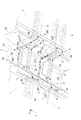
上記の車両のフロア構造として、従来、図11に示す構造があった。この従来の構造について説明すると、フロアトンネル2と左右のサイドシルインナ3を連結する左右一対のクロスメンバ4が、フロアパネル1の上面に左右に並んで溶接接合されている。
また、フロアトンネル2の左右両側に、左側シート用のシート取り付け部と右側シート用のシート取り付け部が各別に配設されている。
各シート取り付け部は、フロアトンネル2側の第1前側シート取り付けブラケット11と、サイドシルインナ3側の第2前側シート取り付けブラケット12と、フロアトンネル2側の第1後側シート取り付けブラケット13と、サイドシルインナ3側の第2後側シート取り付けブラケット14とから成る。
第1前側シート取り付けブラケット11は、フロアトンネル2の側壁2Sとクロスメンバ4の一端部の上面とにわたって接合されている。そして、第2前側シート取り付けブラケット12は、クロスメンバ4の他端部の上面に接合されている。符号Frは車両前方側、Rrは車両後方側である。クロスメンバがフロアパネルの上面に設けられた技術として特許文献1に示す技術がある。
上記従来の構造において、左右の第1前側シート取り付けブラケット11が各別に接合されるフロアトンネル2の左右両側壁2Sは、フロアトンネル2の上壁2Jを介して連結されているだけであった。
Conventionally, there has been a structure shown in FIG. 11 as the floor structure of the vehicle. Explaining this conventional structure, a pair of left and
In addition, on the left and right sides of the
Each seat mounting portion includes a first front
The first front
In the above-described conventional structure, the left and
上記従来の車両のフロア構造では、フロアトンネル2の左右両側壁2Sは、フロアトンネル2の上壁2Jを介して連結されているだけであったために、フロアトンネル2の剛性が十分ではなく、左側のクロスメンバと右側のクロスメンバの連結強度が十分ではなかった。
その結果、左側のサイドシル、左側のクロスメンバ、フロアトンネル、右側のクロスメンバ、右側のサイドシルを強固に連続一体化させることができず、左右のシート取り付け部が設けられたフロアの剛性が低くなって、フロアの振動や車室内音が発生しやすかった。
本発明の目的は、振動や車室内音を十分低減させることができる車両のフロア構造を提供する点にある。
In the above-described conventional vehicle floor structure, the left and
As a result, the left side sill, the left side cross member, the floor tunnel, the right side cross member, and the right side sill cannot be firmly and continuously integrated, and the rigidity of the floor provided with the left and right seat mounting portions is reduced. As a result, floor vibration and vehicle interior noise were likely to occur.
An object of the present invention is to provide a vehicle floor structure that can sufficiently reduce vibration and vehicle interior sound.
本発明の特徴は、
フロアトンネルと左右のサイドシルインナを連結する左右一対のクロスメンバが、前記フロアトンネルの左右両側のフロアパネルの上面に左右に並んで接合され、
前記フロアトンネルの左右両側に、左側のシート用のシート取り付け部と、右側のシート用のシート取り付け部とが配設され、
各シート取り付け部は、前記フロアトンネル側の第1シート取り付けブラケットと、前記サイドシルインナ側の第2シート取り付けブラケットとを備えている車両のフロア構造であって、
前記第1シート取り付けブラケットは、前記フロアトンネルの側壁と前記クロスメンバの一端部の上面とにわたって接合され、
前記第2シート取り付けブラケットは、前記クロスメンバの他端部の上面に接合され、
前記第1シート取り付けブラケットが接合される前記フロアトンネルの左右両側壁の接合部の裏面にトンネルブレースが架設されている点にある。(請求項1)
The feature of the present invention is that
A pair of left and right cross members that connect the floor tunnel and the left and right side sill inners are joined side by side on the upper surface of the floor panels on the left and right sides of the floor tunnel,
On the left and right sides of the floor tunnel, a left seat mounting portion and a right seat mounting portion are disposed,
Each seat mounting portion is a vehicle floor structure including a first seat mounting bracket on the floor tunnel side and a second seat mounting bracket on the side sill inner side,
The first seat mounting bracket is joined across the side wall of the floor tunnel and the upper surface of one end of the cross member,
The second seat mounting bracket is joined to the upper surface of the other end of the cross member,
A tunnel brace is constructed on the back surface of the joint portion of the left and right side walls of the floor tunnel to which the first seat mounting bracket is joined. (Claim 1)
上記の構成によれば、左側のクロスメンバの右端部と右側のクロスメンバの左端部とを、左右一対の第1シート取り付けブラケットとトンネルブレースを介して強固に連結することができ、左右一対のクロスメンバ同士の連結強度を向上させることができる。
その結果、比較的軽量なトンネルブレースを追加するだけで、左側のサイドシル、左側のクロスメンバ、フロアトンネル、右側のクロスメンバ、右側のサイドシルを強固に一体化して車幅方向に連続させることができる。
これにより、左右のシート取り付け部が設けられたフロアの剛性を、重量の増加を抑制した状態で向上させることができ、フロアの振動や車室内音を、より確実に低減させることができる。(請求項1)
According to the above configuration, the right end portion of the left cross member and the left end portion of the right cross member can be firmly connected via the pair of left and right first seat mounting brackets and the tunnel brace. The connection strength between the cross members can be improved.
As a result, the left side sill, the left cross member, the floor tunnel, the right cross member, and the right side sill can be firmly integrated and continued in the vehicle width direction simply by adding a relatively lightweight tunnel brace. .
As a result, the rigidity of the floor on which the left and right seat mounting portions are provided can be improved in a state in which an increase in weight is suppressed, and floor vibration and vehicle interior noise can be more reliably reduced. (Claim 1)
本発明において、
前記クロスメンバの一端部に、車両前方側に張り出す取り付けフランジと、車両後方側に張り出す取り付けフランジとが設けられ、
前記第1シート取り付けブラケットに、車両前方側に張り出す取り付けフランジと、車両後方側に張り出す取り付けフランジとが設けられ、
前記第1シート取り付けブラケットの車両前方側の取り付けフランジと前記フロアトンネルの側壁とが、前記クロスメンバの車両前方側の取り付けフランジを挟み込んで一体に接合されるとともに、
前記第1シート取り付けブラケットの車両後方側の取り付けフランジと前記フロアトンネルの側壁とが、前記クロスメンバの車両後方側の取り付けフランジを挟み込んで一体に接合されていると、次の作用を奏することができる。(請求項2)
In the present invention,
At one end of the cross member, a mounting flange projecting to the vehicle front side and a mounting flange projecting to the vehicle rear side are provided,
The first seat mounting bracket is provided with a mounting flange projecting to the vehicle front side and a mounting flange projecting to the vehicle rear side,
A mounting flange on the vehicle front side of the first seat mounting bracket and a side wall of the floor tunnel are integrally joined with the mounting flange on the vehicle front side of the cross member interposed therebetween,
If the mounting flange on the vehicle rear side of the first seat mounting bracket and the side wall of the floor tunnel are joined together with the mounting flange on the vehicle rear side of the cross member interposed therebetween, the following effects can be obtained. it can. (Claim 2)
クロスメンバの車幅方向の一端部とフロアトンネルの側壁との接合強度を向上させることができる。(請求項2) The joining strength between the one end of the cross member in the vehicle width direction and the side wall of the floor tunnel can be improved. (Claim 2)
本発明において、
前記第1シート取り付けブラケットの上端部に設けられた上側取り付け部が、前記フロアトンネルの上壁と側壁により形成される上側コーナー部の表側の面に重ね合わされて接合されていると、次の作用を奏することができる。(請求項3)
In the present invention,
When the upper mounting portion provided at the upper end portion of the first seat mounting bracket is overlapped and joined to the front side surface of the upper corner portion formed by the upper wall and the side wall of the floor tunnel, the following operation is performed. Can be played. (Claim 3)
フロアトンネルの上側コーナー部は、フロアトンネルの他の平坦な部分よりも剛性を備えている。このように、剛性を備えたフロアトンネルの上側コーナー部に、第1シート取り付けブラケットの上側取り付け部が接合されるから、第1シート取り付けブラケットとフロアトンネルとの接合強度を向上させることができる。(請求項3) The upper corner portion of the floor tunnel is more rigid than other flat portions of the floor tunnel. As described above, since the upper mounting portion of the first seat mounting bracket is joined to the upper corner portion of the floor tunnel having rigidity, the joint strength between the first seat mounting bracket and the floor tunnel can be improved. (Claim 3)
本発明において、
前記トンネルブレースの上端部に設けられた上側取り付け部が、前記フロアトンネルの上側コーナー部の裏側の面に重ね合わされ、
前記トンネルブレースの上側取り付け部と前記第1シート取り付けブラケットの上側取り付け部とが、前記フロアトンネルの上側コーナー部を挟み込んで一体に接合されていると、次の作用を奏することができる。(請求項4)
In the present invention,
The upper mounting portion provided at the upper end portion of the tunnel brace is superimposed on the back side surface of the upper corner portion of the floor tunnel,
When the upper mounting portion of the tunnel brace and the upper mounting portion of the first seat mounting bracket are joined together with the upper corner portion of the floor tunnel sandwiched therebetween, the following effects can be achieved. (Claim 4)
第1シート取り付けブラケットとフロアトンネルとトンネルブレースの接合強度を、より向上させることができる。(請求項4) The joint strength of the first seat mounting bracket, the floor tunnel, and the tunnel brace can be further improved. (Claim 4)
本発明において、
前記フロアトンネルの下方のフロアパネルは開口して、前記フロアトンネルの側壁と前記フロアパネルにより左右一対の下側コーナー部が形成され、
前記トンネルブレースの左右両側の下端部に設けられた下側取り付け部が、前記左右一対の下側コーナー部の裏側の面に各別に重ね合わされて接合されていると、次の作用を奏することができる。(請求項5)
In the present invention,
The floor panel below the floor tunnel is opened, and a pair of left and right lower corners are formed by the side wall of the floor tunnel and the floor panel,
When the lower attachment portions provided at the lower left and right ends of the tunnel brace are overlapped and joined to the back side surfaces of the pair of left and right lower corner portions, the following effects can be obtained. it can. (Claim 5)
前記フロアトンネルの側壁と前記フロアパネルにより形成される左右一対の下側コーナー部は剛性を備えている。このように、剛性を備えた左右一対の下側コーナー部の裏側の面に、トンネルブレースの左右の下側取り付け部が各別に接合されているから、トンネルブレースとフロアパネルとフロアトンネルの接合強度を、より向上させることができる。(請求項5)、 A pair of left and right lower corners formed by the side wall of the floor tunnel and the floor panel has rigidity. In this way, the left and right lower mounting parts of the tunnel brace are joined to the back surface of the pair of left and right lower corners with rigidity, so the joint strength of the tunnel brace, floor panel, and floor tunnel Can be further improved. (Claim 5),
本発明において、
前記クロスメンバの一端部に、前記下側コーナー部の表側の面に重なる取り付けフランジが設けられ、
この取り付けフランジと、前記トンネルブレースの下側取り付け部とが前記下側コーナー部を挟み込んで一体に接合されていると、次の作用を奏することができる。(請求項6)
In the present invention,
At one end of the cross member, a mounting flange is provided that overlaps the front side surface of the lower corner portion,
When this attachment flange and the lower attachment portion of the tunnel brace are joined together with the lower corner portion interposed therebetween, the following effects can be obtained. (Claim 6)
クロスメンバの一端部とトンネルブレースとフロアパネルとフロアトンネルの接合強度を、より向上させることができる。(請求項6) The joining strength of the one end part of the cross member, the tunnel brace, the floor panel, and the floor tunnel can be further improved. (Claim 6)
本発明において、
前記サイドシルインナは、車幅方向外側が開放した断面コの字状に形成され、
前記クロスメンバとの接合部付近の前記サイドシルインナの上下壁間にバルクヘッドが架設されていると、次の作用を奏することができる。(請求項7)
In the present invention,
The side sill inner is formed in a U-shaped cross section with the vehicle width direction outer side open,
When a bulkhead is installed between the upper and lower walls of the side sill inner in the vicinity of the joint with the cross member, the following effects can be achieved. (Claim 7)
サイドシルインナとクロスメンバとの接合強度を向上させることができる。(請求項7) The joint strength between the side sill inner and the cross member can be improved. (Claim 7)
本発明において、
前記第2シート取り付けブラケットのサイドシルインナ側の端部に、車幅方向外側に延びる取り付けフランジが設けられ、
この取り付けフランジと前記バルクヘッドとが前記サイドシルインナの上壁を挟み込んで一体に接合されていると、次の作用を奏することができる。(請求項8)
In the present invention,
A mounting flange extending outward in the vehicle width direction is provided at the side sill inner side end of the second seat mounting bracket,
When the mounting flange and the bulkhead are integrally joined with the upper wall of the side sill inner interposed therebetween, the following effects can be achieved. (Claim 8)
第2シート取り付けブラケットとサイドシルインナの接合強度を、より向上させることができる。(請求項8) The joint strength between the second seat mounting bracket and the side sill inner can be further improved. (Claim 8)
本発明によれば、
振動や車室内音を十分低減させることができる車両のフロア構造を提供することができた。
According to the present invention,
It was possible to provide a vehicle floor structure that can sufficiently reduce vibration and vehicle interior sound.
以下、本発明の実施の形態を図面に基づいて説明する。
図1,図3に示すように、フロアパネル1の左右中央部に、上方に膨出するフロアトンネル2が車両前後方向に沿って形成されている。また、フロアトンネル2と、車両前後方向に沿う左右のサイドシルインナ3とを連結する左右一対の第1クロスメンバ4が、フロアトンネル2の左右両側のフロアパネル1の上面に左右に並んで溶接接合されている。
Hereinafter, embodiments of the present invention will be described with reference to the drawings.
As shown in FIGS. 1 and 3, a
[フロアトンネル2の構造]
フロアトンネル2は、車両前後方向から見た縦断面形状が台形状に設定され、上端部側ほどフロアトンネル2の幅方向中央側に位置する左右一対の傾斜した側壁2Sと、左右一対の側壁2Sの上端部同士を連結する上壁2Jとを備えている。 フロアトンネル2の下方のフロアパネル1は開口している。
[Structure of floor tunnel 2]
The
[サイドシルの構造]
サイドシルインナ3(サイドシルインナパネル)は、車幅方向外側W2が開放した断面ハット形状(断面コの字状部を備えている)に形成されている。このサイドシルインナ3は、車幅方向内側W1が開放した断面ハット形状のサイドシルアウタ(サイドシルアウタパネル)とサイドシルリンフォース(いずれも図示せず)に一体に溶接接合されて、これらの部品と共にサイドシルを構成する。
[Structure of side sill]
The side sill inner 3 (side sill inner panel) is formed in a cross-sectional hat shape (provided with a U-shaped cross section) that is open on the outer side W2 in the vehicle width direction. The side sill inner 3 is integrally welded to a side sill outer (side sill outer panel) and a side sill reinforcement (both not shown) having a hat-shaped cross section with the vehicle width direction inner side W1 open. To do.
[第1クロスメンバ4の構造]
図3,図4に示すように、第1クロスメンバ4(クロスメンバに相当)は、下側が開放した断面ハット形状に形成され、第1クロスメンバ4の前後一対の下側の取り付けフランジ4F1がフロアパネル1に溶接接合されている。
[Structure of the first cross member 4]
As shown in FIGS. 3 and 4, the first cross member 4 (corresponding to the cross member) is formed in a cross-sectional hat shape in which the lower side is open, and a pair of lower and
第1クロスメンバ4の長手方向の一端部には、車両前方側Frに張り出す取り付けフランジと、車両後方側Rrに張り出す取り付けフランジ4F2とが設けられている。また、第1クロスメンバ4の長手方向の他端部に、車両前方側Frに張り出す取り付けフランジ4F3(図9(c)参照)と、車両後方側Rrに張り出す取り付けフランジ4F3(図3,図9(c)参照)とが形成されている。
One end of the
そして、図3に示すように、前記一端部の取り付けフランジ4F2が、フロアトンネル2の側壁2Sに溶接接合され、図9(c)に示すように、前記他端部の取り付けフランジ4F3が、サイドシルインナ3の縦壁3Tに溶接接合されている。
Then, as shown in FIG. 3, the mounting flange 4F2 at the one end is welded to the
[シート取り付け部5,6の構造]
図3に示すように、フロアトンネル2の左右両側に、左側フロントシート用のシート取り付け部5と右側フロントシート用のシート取り付け部6とが各別に配設されている。
[Structure of the
As shown in FIG. 3, a
各シート取り付け部5,6は、フロアトンネル2側の第1前側シート取り付けブラケット11と、サイドシルインナ3側の第2前側シート取り付けブラケット12と、フロアトンネル2側の第1後側シート取り付けブラケット13と、サイドシルインナ3側の第2後側シート取り付けブラケット14とから成る。
Each of the
左側フロントシート用のシート取り付け部5の各シート取り付けブラケット11,12,13,14と、右側フロントシート用のシート取り付け部6の各シート取り付けブラケット11,12,13,14との対応するもの同士は同一構造であり同一取り付け構造である。また、対応する左右一対のシート取り付けブラケット(例えば、左側の第1前側シート取り付けブラケット11と右側の第1前側シート取り付けブラケット11)は、フロアトンネル2の左右中心に対して左右対称に取り付けられる。
Corresponding parts between the respective
以下、左側フロントシート用のシート取り付け部5の各シート取り付けブラケット11,12,13,14の構造とその取り付け構造について説明し、右側フロントシート用のシート取り付け部6の各シート取り付けブラケット11,12,13,14の構造とその取り付け構造の説明は省略する。
Hereinafter, the structure and the mounting structure of the respective
[第1前側シート取り付けブラケット11の構造とその取り付け構造]
図4,図10(a)に示すように、左側のシート取り付け部5の第1前側シート取り付けブラケット11(第1シート取り付けブラケットに相当)は、車両前後方向から見てフロアトンネル2側に傾斜した上窄まりの台形状の前壁11M・後壁11Kと、前壁11M・後壁11Kのサイドシルインナ3側(車幅方向外側W2)の端部同士を連結する側壁11Sと、前壁11Mと後壁11Kと側壁11Sの上端部に架け渡された略水平の上壁11Jとを備えている。上壁11Jには、左側フロントシートに対する取り付け部が設けられている。
[Structure of first front
As shown in FIGS. 4 and 10A, the first front seat mounting bracket 11 (corresponding to the first seat mounting bracket) of the left
前壁11Mの下端部と後壁11Kの下端部は第1クロスメンバ4の一端部(右端部)に外嵌して車両前後方向で溶接接合されている。図10(a)の黒丸はスポット溶接による溶接部Aである。その他の図の黒丸も同様に溶接部Aを示す。また、前壁11Mの下端部と後壁11Kの下端部と側壁11Sの下端部に、車幅方向から見て下側が開放した断面コの字状の取り付け壁11Fが、サイドシルインナ3側に延びる状態に連設されている。そして、前記取り付け壁11Fが第1クロスメンバ4の一端部に外嵌して溶接接合されている。
The lower end portion of the
図10(b)にも示すように、前記前壁11Mのフロアトンネル2側の端部と後壁11Kのフロアトンネル2側の端部とから、車両前後方向に前後一対の取り付けフランジ11F1が張り出している。つまり、第1前側シート取り付けブラケット11に、車両前方側Frに張り出す取り付けフランジ11F1と、車両後方側Rrに張り出す取り付けフランジ11F1とが設けられている。
As shown in FIG. 10B, a pair of front and rear mounting flanges 11F1 project in the vehicle longitudinal direction from the end of the
そして、第1前側シート取り付けブラケット11の車両前方側Frの取り付けフランジ11F1とフロアトンネル2の側壁2Sとが、第1クロスメンバ4の車両前方側Frの取り付けフランジを挟み込んで一体に溶接接合されている。さらに、第1前側シート取り付けブラケット11の車両後方側Rrの取り付けフランジ11F1とフロアトンネル2の側壁2Sとが、第1クロスメンバ4の車両後方側Rrの取り付けフランジ4F2を挟み込んで一体に溶接接合されている。これにより、第1クロスメンバ4の車幅方向の一端部とフロアトンネル2の側壁2Sとの接合強度を向上させることができる。
Then, the mounting flange 11F1 on the vehicle front side Fr of the first front
図4,図10(a),図10(b)に示すように、両取り付けフランジ11F1の上端と、上壁11Jのフロアトンネル2側の一端とから断面L字状の上側取り付け壁11F2(上側取り付け部に相当)が上方に張り出している。そして、この上側取り付け壁11F2が、フロアトンネル2の上壁2Jと側壁2Sにより形成される第1上側コーナー部10の表側の面に重ね合わされて溶接接合されている。
As shown in FIGS. 4, 10A and 10B, an upper mounting wall 11F2 (upper side) having an L-shaped cross section from the upper end of both mounting flanges 11F1 and one end of the
フロアトンネル2の第1上側コーナー部10は剛性を備えている。このように、剛性を備えたフロアトンネルの第1上側コーナー部10に、前記上側取り付け壁11F2が溶接接合されるから、第1前側シート取り付けブラケット11とフロアトンネル2との接合強度を向上させることができる。
The first
上記のように、第1前側シート取り付けブラケット11は、フロアトンネル2の上壁2Jと側壁2Sと第1クロスメンバ4の一端部の上面とにわたって溶接接合されている。
As described above, the first front
[第2前側シート取り付けブラケット12の構造とその取り付け構造]
図4,図9(a),図9(b)に示すように、左側のシート取り付け部5の第2前側シート取り付けブラケット12(第2シート取り付けブラケットに相当)は、上端部側ほどフロアトンネル2側に位置するように傾斜したサイドシルインナ3側の側壁12S1と、上端部側ほどサイドシルインナ3側に位置するように傾斜したフロアトンネル2側の側壁12S2と、これらの上端部同士を連結する略水平の上壁12Jとを備えている。上壁12Jには左側フロントシートに対する取り付け部が設けられている。サイドシルインナ3側の側壁12S1はフロアトンネル2側の側壁12S2よりも傾斜が緩やかに設定されている。
[Structure and Mounting Structure of Second Front Seat Mounting Bracket 12]
As shown in FIGS. 4, 9A, and 9B, the second front seat mounting bracket 12 (corresponding to the second seat mounting bracket) of the left
また、サイドシルインナ3側の側壁12S1のサイドシルインナ3側の端部に、車幅方向から見て下側が開放した断面コの字状の取り付け壁12Fが、サイドシルインナ3側に延びる状態に連設されている。そして、この取り付け壁12Fが、第1クロスメンバ4の他端部(左端部)の上面等に外嵌して溶接接合されている。さらに、前記取り付け壁12Fの上壁からサイドシルインナ3側に取り付けフランジ12F1が延出している。このように、第2前側シート取り付けブラケット12のサイドシルインナ3側の端部に、車幅方向外側W2に延びる取り付けフランジ12F1が設けられている。そして、前記取り付けフランジ12F1がサイドシルインナ3の上壁3Jに溶接接合されている。
Also, a side wall 12S1 on the side sill inner 3 side is provided with a
また、フロアトンネル2側の側壁12S2のフロアトンネル2側の端部に、車幅方向から見て下側が開放した断面コの字状の取り付け壁12Gが、フロアトンネル2側に延びる状態に連設されている。そして、取り付け壁12Gが、第1クロスメンバ4の上面等に外嵌して溶接接合されている。
Further, a
サイドシルインナ3側の側壁12S1とフロアトンネル2側の側壁12S2と上壁12Jの車両前後方向の両端部には、各取り付け壁12F,12Gの前壁と後壁に連なるフランジ12F2が形成されている。これにより、第2前側シート取り付けブラケット12の剛性を向上させることができる。
At both ends of the side wall 12S1 on the side sill inner 3 side, the side wall 12S2 on the
[第2クロスメンバ15の構造]
図1,図3に示すように、前記第1後側シート取り付けブラケット13と第2後側シート取り付けブラケット14を連結する左右一対の第2クロスメンバ15(クロスメンバに相当)が、前記フロアパネル1の上面に左右に並んで溶接接合されている。
[Structure of second cross member 15]
As shown in FIGS. 1 and 3, a pair of left and right second cross members 15 (corresponding to cross members) connecting the first rear
第2クロスメンバ15は、下側が開放した断面ハット形状に形成され、第2クロスメンバ15の前後一対の下側の取り付けフランジ15F1がフロアパネル1に溶接接合されている。
The
[第1後側シート取り付けブラケット13の構造]
図4,図10(a),図10(c)に示すように、左側のシート取り付け部5の第1後側シート取り付けブラケット13(第1シート取り付けブラケットに相当)は、車両前後方向から見て下窄まりの台形状の前壁13M・後壁13Kと、前壁13M・後壁13Kのサイドシルインナ3側の端部同士を連結する側壁13Sと、前壁13Mと後壁13Kと側壁13Sの上端部に架け渡された上壁13Jとを備えている。上壁13Jには左側フロントシートに対する取り付け部が設けられている。
[Structure of the first rear seat mounting bracket 13]
As shown in FIGS. 4, 10 (a) and 10 (c), the first rear seat mounting bracket 13 (corresponding to the first seat mounting bracket) of the left
前壁13Mと後壁13Kと側壁13Sの下端部には、車幅方向から見て断面ハット形状の取り付け壁13Fが、サイドシルインナ3側に延びる状態に連設されている。そして、取り付け壁13Fが第2クロスメンバ15の一端部(右端部)の上面等に外嵌して溶接接合されている。さらに、取り付け壁13Fの下端部の前後一対の取り付けフランジ13F1(図4,図8参照)が、フロアパネル1の上面、及び、第2クロスメンバ15の前後一対の下側の取り付けフランジ15F1に溶接接合されている。
An
図10(c)にも示すように、前壁13Mのフロアトンネル2側の端部と後壁13Kのフロアトンネル2側の端部とから、車両前後方向に前後一対の取り付けフランジ13F2が張り出している。つまり、第1後側シート取り付けブラケット13に、車両前方側Frに張り出す取り付けフランジ13F2と、車両後方側Rrに張り出す取り付けフランジ13F2とが設けられている。そして、両取り付けフランジ13F2がフロアトンネル2の側壁2Sに溶接接合されている。
As shown in FIG. 10C, a pair of front and rear mounting flanges 13F2 project in the vehicle longitudinal direction from the end of the
図4,図10(a),図10(c)に示すように、両取り付けフランジ13F2の上端と、上壁13Jのフロアトンネル2側の一端とから断面L字状の上側取り付け壁13F3(上側取り付け部に相当)が上方に張り出している。そして、この上側取り付け壁13F3が、フロアトンネル2の上壁2Jと側壁2Sにより形成される第2上側コーナー部20の表側の面に重ね合わされて溶接接合されている。
As shown in FIGS. 4, 10A and 10C, an upper mounting wall 13F3 (upper side) having an L-shaped cross section is formed from the upper end of both mounting flanges 13F2 and one end of the
上記のように、第1後側シート取り付けブラケット13は、フロアトンネル2の上壁2Jと側壁2Sと第1クロスメンバ4の一端部の上面とにわたって溶接接合されている。
As described above, the first rear
[第2後側シート取り付けブラケット14の構造]
図4に示すように、左側のシート取り付け部5の第2後側シート取り付けブラケット14は、互いに同一形状の前壁と後壁14Kを備えるとともに、前記前壁と後壁14Kの上端部間の上壁14Jを備えている。
[Structure of Second Rear Seat Mounting Bracket 14]
As shown in FIG. 4, the second rear
フロアトンネル2側の後壁部分14K1は長方形状に形成され、サイドシルインナ3側の後壁部分14K2は、前記フロアトンネル2側の後壁部分14K1よりも上下幅が短い長方形状に形成されている。そして、これらの間の後壁中間部分14K3が、サイドシルインナ3側に向かって窄まる台形状に形成されている。サイドシルインナ3側の後壁部分14K2の上端と上壁14Jの間、及び、前記後壁中間部分14K3と上壁14Jの間にはスリットSが形成されている。前記上壁14Jは、各後壁部分14K1,14K2,14K3の上端縁に沿って屈曲している。
The rear wall portion 14K1 on the
フロアトンネル2側の後壁部分14K1の下端部には、車両前後方向に張り出す前後一対の取り付けフランジ14F1が形成されている。そして、取り付けフランジ14F1とフロアパネル1が、第2クロスメンバ15の取り付けフランジ15F1を挟み込んで一体に溶接接合されている。
A pair of front and rear mounting flanges 14F1 projecting in the vehicle front-rear direction are formed at the lower end of the rear wall portion 14K1 on the
また、サイドシルインナ3側の後壁部分14K2のサイドシルインナ3側の端部に、車両後方側Rrに張り出す前後一対の取り付けフランジ14F2(図3参照、図3の取り付けフランジ14F2は、右側フロントシート用のシート取り付け部6の構造である)が形成されている。そして、取り付けフランジ14F2がサイドシルインナ3の側壁3Tに溶接接合されている。
A pair of front and rear mounting flanges 14F2 projecting to the vehicle rear side Rr at the end of the rear wall portion 14K2 on the side sill inner 3 side (see FIG. 3, the mounting flange 14F2 in FIG. 3 is the right front seat). This is the structure of the
さらに、図4に示すように、上壁14Jのサイドシルインナ3側の端部に、サイドシルインナ3側に延びる取り付けフランジ14F3が形成され、この取り付けフランジ14F3が、サイドシルインナ3の上壁3Jに溶接接合されている。
Further, as shown in FIG. 4, a mounting flange 14F3 extending to the side sill inner 3 side is formed at the end of the
[前側トンネルブレース17の構造]
図2,図3,図5,図6,図10(b)に示すように、第1前側シート取り付けブラケット11が接合されるフロアトンネル2の左右両側壁2Sの接合部の裏面に前側トンネルブレース17(トンネルブレースに相当)が架設されている。
[Structure of front tunnel brace 17]
As shown in FIGS. 2, 3, 5, 6, and 10 (b), the front tunnel brace is formed on the back surface of the joint portion of the left and
前側トンネルブレース17は、車幅方向から見て上側が開放した断面ハット形状に形成されている。この前側トンネルブレース17の前壁17Mと後壁17Kは、車両前後方向から見て台形状に形成されている。そして、前壁17Mと後壁17Kの周部に張り出し形成された取り付けフランジ17F1が、フロアトンネル2の上壁2Jの裏面と左右両側壁2Sの裏面に溶接接合されている。
The front
詳述すると、図5,図10(b)に示すように、前記前壁17Mと後壁17Kの上端部の上側コーナー部から張り出す前記取り付けフランジ17F1(上側取り付け部に相当)が、フロアトンネル2の第1上側コーナー部10の裏側の面に重ね合わされている。そして、前記取り付けフランジ17F1と、第1前側シート取り付けブラケット11の上側取り付け壁11F2とが、フロアトンネル2の第1上側コーナー部10を挟み込んで一体に溶接接合されている。これにより、第1前側シート取り付けブラケット11とフロアトンネル2と前側トンネルブレース17の接合強度を、より向上させることができる。
More specifically, as shown in FIGS. 5 and 10 (b), the mounting flange 17F1 (corresponding to the upper mounting portion) protruding from the upper corner portion of the upper ends of the
また、図5に示すように、前側トンネルブレース17の左右の下端部に、上下方向に長い左右一対の前側リンフォース37の上端部が溶接接合されている。前側リンフォース37は断面ハット形状であり、下端側ほどフロアトンネル2の幅方向外側に位置するように傾斜して、フロアトンネル2の側壁2Sに沿っている。
As shown in FIG. 5, the upper ends of a pair of left and right
前側リンフォース37の下端部は、車幅方向から見てL字の取り付け壁37F(下側取り付け部に相当)に構成されている。この構造に換えて、取り付け壁37Fが前側トンネルブレース17の下端部に一体に設けられた構造であってもよい。そして、左右一対の前側リンフォース37の取り付け壁37Fが、フロアトンネル2の側壁2Sとフロアパネル1により形成される左右一対の第1下側コーナー部30の裏側の面に各別に重ね合わされている。
A lower end portion of the
また、左右一対の第1クロスメンバ4の一端部に形成された下側のコーナー部から張り出す取り付けフランジ4F4(図7参照)が、左右一対の第1下側コーナー部30の表側の面に各別に重なり、前記取り付けフランジ4F4と前記取り付け壁37Fが、第1下側コーナー部30を挟み込んで一体に溶接接合されている。
Further, mounting flanges 4F4 (see FIG. 7) projecting from lower corner portions formed at one end portions of the pair of left and right
前記第1下側コーナー部30は剛性を備えている。このように、剛性を備えた左右一対の第1下側コーナー部30の裏側の面に、前側トンネルブレース17の左右の取り付け壁37Fが各別に接合されているから、前側トンネルブレース17とフロアパネル1とフロアトンネル2の接合強度を向上させることができる。また、前記取り付けフランジ4F4と前記取り付け壁37Fが、第1下側コーナー部30を挟み込んで一体に溶接接合されていることで、接合強度を、より向上させることができる。
The first
[後側トンネルブレース18の構造]
図2,図3,図5,図10(c)に示すように、第1後側シート取り付けブラケット13が接合されるフロアトンネル2の左右両側壁2Sの接合部の裏面に後側トンネルブレース18(トンネルブレースに相当)が架設されている。
[Structure of rear tunnel brace 18]
As shown in FIGS. 2, 3, 5, and 10 (c), the
後側トンネルブレース18は、車幅方向から見て上側が開放した断面ハット形状に形成されている。この後側トンネルブレース18の前壁18Mと後壁18Kは、車両前後方向から見て台形状に形成されている。そして、前壁18Mと後壁18Kの周部に張り出し形成された取り付けフランジ18F1が、フロアトンネル2の上壁2Jの裏面と左右両側壁2Sの裏面に溶接接合されている。
The rear
詳述すると、図10(c)に示すように、前記前壁18Mと後壁18Kの上端部の上側コーナー部から張り出す前記取り付けフランジ18F1(上側取り付け部に相当)が、フロアトンネル2の第2上側コーナー部20の裏側の面に重ね合わされている。そして、前記取り付けフランジ18F1と、第2前側シート取り付けブラケット13の上側取り付け壁13F3とが、フロアトンネル2の第2上側コーナー部20を挟み込んで一体に溶接接合されている。
More specifically, as shown in FIG. 10 (c), the mounting flange 18F1 (corresponding to the upper mounting portion) protruding from the upper corner portions of the upper ends of the
また、図5に示すように、後側トンネルブレース18の左右の下端部に、上下方向に長い左右一対の後側リンフォース38の上端部が溶接接合されている。後側リンフォース38は断面ハット形状であり、下端側ほどフロアトンネル2の幅方向外側に位置するように傾斜して、フロアトンネル2の側壁2Sに沿っている。
As shown in FIG. 5, the upper ends of a pair of left and right
後側リンフォース38の下端部は、車幅方向から見てL字の取り付け壁38F(下側取り付け部に相当)に構成されている。この構造に換えて、取り付け壁38Fが後側トンネルブレース18の下端部に一体に設けられた構造であってもよい。そして、左右一対の後側リンフォース38の取り付け壁38Fが、フロアトンネル2の側壁2Sとフロアパネル1により形成される左右一対の第2下側コーナー部40の裏側の面に各別に重ね合わされている。
A lower end portion of the
また、図8に示すように、左右一対の第2前側シート取り付けブラケット13の前壁13Mと後壁13Kから張り出す取り付けフランジ13F4が、左右一対の第2下側コーナー部40の表側の面に重なり、前記取り付けフランジ13F4と前記取り付け壁38Fが、第2下側コーナー部40を挟み込んで一体に溶接接合されている。
Further, as shown in FIG. 8, mounting flanges 13F4 projecting from the
[バルクヘッド19の構造]
図1,図9(a),図9(b)に示すように、第1クロスメンバ4との接合部付近のサイドシルインナ3の上下壁3J,3K間と、第2クロスメンバ15との接合部付近の前記サイドシルインナ3の上下壁3J,3K間とにバルクヘッド19が架設されている。
[Structure of bulkhead 19]
As shown in FIGS. 1, 9 (a), and 9 (b), the joint between the upper and
このバルクヘッド19は、壁面が車両前後方向を向く上下方向に細長い縦壁19Tと、縦壁19Tの上下両端部及び車幅方向内側W1の端部から車両後方側Rrに延びる周壁19Sと、周壁19Sの上下両端部及び上下方向中間部から車両後方側Rrに延びる取り付けフランジ19F1,19F2,19F3とから成る。
The
そして、上下一対の取り付けフランジ19F1,19F2がサイドシルインナ3の上壁3Jと下壁3Kの内面に各別に溶接接合され、上下方向中間部の取り付けフランジ19F2がサイドシルインナ3の縦壁3Tの内面に溶接接合されている。
Then, a pair of upper and lower mounting flanges 19F1 and 19F2 are welded to the inner surfaces of the
図9(b)に示すように、第2前側シート取り付けブラケット12の取り付けフランジ12F1とバルクヘッド19の上側の取り付けフランジ19F1とは、サイドシルインナ3の上壁3Jを挟み込んで一体に溶接接合されている。これにより、第2前側シート取り付けブラケット12とサイドシルインナ3の接合強度を、より向上させることができる。
As shown in FIG. 9B, the mounting flange 12F1 of the second front
また、第2後側シート取り付けブラケット14に設けられた取り付けフランジ14F3とバルクヘッド19の取り付けフランジ19F1とがサイドシルインナ3の上壁3Jを挟み込んで一体に溶接接合されている。これにより、第2後側シート取り付けブラケット14とサイドシルインナ3の接合強度を、より向上させることができる。
Further, the mounting flange 14F3 provided on the second rear
本発明によれば、
左側の第1クロスメンバ4(第2クロスメンバ15)の右端部と、右側の第1クロスメンバ4(第2クロスメンバ15)の左端部とを、左右一対の第1前側シート取り付けブラケット11(第1後側シート取り付けブラケット13)と前側トンネルブレース17(後側トンネルブレース18)を介して強固に連結することができ、左右一対の第1クロスメンバ4(第2クロスメンバ15)同士の連結強度を向上させることができる。
その結果、比較的軽量な前側トンネルブレース17(後側トンネルブレース18)を追加するだけで、左側のサイドシル、左側の第1クロスメンバ4(第2クロスメンバ15)、フロアトンネル2、右側の第1クロスメンバ4(第2クロスメンバ15)、右側のサイドシルを強固に一体化して車幅方向に連続させることができる。
これにより、左右のシート取り付け部5,6が設けられたフロアの剛性を、重量の増加を抑制した状態で向上させることができ、フロアの振動や車室内音を、より確実に低減させることができる。
According to the present invention,
The right end portion of the left first cross member 4 (second cross member 15) and the left end portion of the right first cross member 4 (second cross member 15) are connected to a pair of left and right first front seat mounting brackets 11 ( The first rear seat mounting bracket 13) and the front tunnel brace 17 (rear tunnel brace 18) can be firmly connected, and the pair of left and right first cross members 4 (second cross members 15) are connected to each other. Strength can be improved.
As a result, by simply adding a relatively lightweight front tunnel brace 17 (rear tunnel brace 18), the left side sill, the left first cross member 4 (second cross member 15), the
As a result, the rigidity of the floor on which the left and right
1 フロアパネル
2 フロアトンネル
2J フロアトンネルの上壁
2S フロアトンネルの側壁
3 サイドシルインナ
3J サイドシルインナの上壁
3K サイドシルインナの下壁
4 (第1)クロスメンバ
4F2 車両前方側に張り出す(クロスメンバの)取り付けフランジ
車両後方側に張り出す(クロスメンバの)取り付けフランジ
4F4 下側コーナー部の表側の面に重なる(第1)クロスメンバの取り付けフランジ
5 左側のシート用のシート取り付け部
6 右側のシート用のシート取り付け部
10 (第1)上側コーナー部
11 第1(前側)シート取り付けブラケット
11F1 車両前方側又は車両後方側に張り出す(第1シート取り付けブラケットの)取り付けフランジ、
11F2 第1シート取り付けブラケットの上端部の上側取り付け部
12 第2(前側)シート取り付けブラケット
12F1 第2(前側)シート取り付けブラケットの車幅方向外側に延びる取り付けフランジ
13 第1(後側)シート取り付けブラケット
13F3 第1シート取り付けブラケットの上端部の上側取り付け部
13F4 下側コーナー部の表側の面に重なる(第2)クロスメンバの取り付けフランジ
14 第2(後側)シート取り付けブラケット
14F1 第2(後側)シート取り付けブラケットの車幅方向外側に延びる取り付けフランジ
15 (第2)クロスメンバ
17 (前側)トンネルブレース
17F1(前側)トンネルブレースの上側取り付け部
18 (後側)トンネルブレース
18F1(後側)トンネルブレースの上側取り付け部
19 バルクヘッド
20 (第2)上側コーナー部
30 (第1)下側コーナー部
37F (前側)トンネルブレースの下側取り付け部
38F (後側)トンネルブレースの下側取り付け部
40 (第2)下側コーナー部
Fr 車両前方側
Rr 車両後方側
W2 車幅方向外側
1
11F2
Claims (8)
前記フロアトンネルの左右両側に、左側のシート用のシート取り付け部と、右側のシート用のシート取り付け部とが配設され、
各シート取り付け部は、前記フロアトンネル側の第1シート取り付けブラケットと、前記サイドシルインナ側の第2シート取り付けブラケットとを備えている車両のフロア構造であって、
前記第1シート取り付けブラケットは、前記フロアトンネルの側壁と前記クロスメンバの一端部の上面とにわたって接合され、
前記第2シート取り付けブラケットは、前記クロスメンバの他端部の上面に接合され、
前記第1シート取り付けブラケットが接合される前記フロアトンネルの左右両側壁の接合部の裏面にトンネルブレースが架設されている車両のフロア構造。 A pair of left and right cross members that connect the floor tunnel and the left and right side sill inners are joined side by side on the upper surface of the floor panels on the left and right sides of the floor tunnel,
On the left and right sides of the floor tunnel, a left seat mounting portion and a right seat mounting portion are disposed,
Each seat mounting portion is a vehicle floor structure including a first seat mounting bracket on the floor tunnel side and a second seat mounting bracket on the side sill inner side,
The first seat mounting bracket is joined across the side wall of the floor tunnel and the upper surface of one end of the cross member,
The second seat mounting bracket is joined to the upper surface of the other end of the cross member,
A vehicle floor structure in which a tunnel brace is erected on a back surface of a joint portion between left and right side walls of the floor tunnel to which the first seat mounting bracket is joined.
前記第1シート取り付けブラケットに、車両前方側に張り出す取り付けフランジと、車両後方側に張り出す取り付けフランジとが設けられ、
前記第1シート取り付けブラケットの車両前方側の取り付けフランジと前記フロアトンネルの側壁とが、前記クロスメンバの車両前方側の取り付けフランジを挟み込んで一体に接合されるとともに、
前記第1シート取り付けブラケットの車両後方側の取り付けフランジと前記フロアトンネルの側壁とが、前記クロスメンバの車両後方側の取り付けフランジを挟み込んで一体に接合されている請求項1記載の車両のフロア構造。 At one end of the cross member, a mounting flange projecting to the vehicle front side and a mounting flange projecting to the vehicle rear side are provided,
The first seat mounting bracket is provided with a mounting flange projecting to the vehicle front side and a mounting flange projecting to the vehicle rear side,
A mounting flange on the vehicle front side of the first seat mounting bracket and a side wall of the floor tunnel are integrally joined with the mounting flange on the vehicle front side of the cross member interposed therebetween,
The vehicle floor structure according to claim 1, wherein a mounting flange on the vehicle rear side of the first seat mounting bracket and a side wall of the floor tunnel are integrally joined with a mounting flange on the vehicle rear side of the cross member interposed therebetween. .
前記トンネルブレースの上側取り付け部と前記第1シート取り付けブラケットの上側取り付け部とが、前記フロアトンネルの上側コーナー部を挟み込んで一体に接合されている請求項3記載の車両のフロア構造。 The upper mounting portion provided at the upper end portion of the tunnel brace is superimposed on the back side surface of the upper corner portion of the floor tunnel,
4. The vehicle floor structure according to claim 3, wherein the upper mounting portion of the tunnel brace and the upper mounting portion of the first seat mounting bracket are integrally joined with the upper corner portion of the floor tunnel interposed therebetween.
前記トンネルブレースの左右両側の下端部に設けられた下側取り付け部が、前記左右一対の下側コーナー部の裏側の面に各別に重ね合わされて接合されている請求項1〜4のいずれか一つに記載の車両のフロア構造。 The floor panel below the floor tunnel is opened, and a pair of left and right lower corners are formed by the side wall of the floor tunnel and the floor panel,
The lower attachment part provided in the lower end part of the right-and-left both sides of the said tunnel brace is overlapped and joined separately to the surface of the back side of the said left-right pair of lower corner part. Vehicle floor structure described in 1.
この取り付けフランジと、前記トンネルブレースの下側取り付け部とが前記下側コーナー部を挟み込んで一体に接合されている請求項5記載の車両のフロア構造。 At one end of the cross member, a mounting flange is provided that overlaps the front side surface of the lower corner portion,
The vehicle floor structure according to claim 5, wherein the mounting flange and a lower mounting portion of the tunnel brace are integrally joined with the lower corner portion interposed therebetween.
前記クロスメンバとの接合部付近の前記サイドシルインナの上下壁間にバルクヘッドが架設されている請求項1〜6のいずれか一つに記載の車両のフロア構造。 The side sill inner is formed in a U-shaped cross section with the vehicle width direction outer side open,
The vehicle floor structure according to any one of claims 1 to 6, wherein a bulkhead is provided between upper and lower walls of the side sill inner near a joint portion with the cross member.
この取り付けフランジと前記バルクヘッドとが前記サイドシルインナの上壁を挟み込んで一体に接合されている請求項7記載の車両のフロア構造。
A mounting flange extending outward in the vehicle width direction is provided at the side sill inner side end of the second seat mounting bracket,
The vehicle floor structure according to claim 7, wherein the mounting flange and the bulkhead are integrally joined with an upper wall of the side sill inner interposed therebetween.
Priority Applications (1)
| Application Number | Priority Date | Filing Date | Title |
|---|---|---|---|
| JP2015097192A JP6485200B2 (en) | 2015-05-12 | 2015-05-12 | Vehicle floor structure |
Applications Claiming Priority (1)
| Application Number | Priority Date | Filing Date | Title |
|---|---|---|---|
| JP2015097192A JP6485200B2 (en) | 2015-05-12 | 2015-05-12 | Vehicle floor structure |
Publications (2)
| Publication Number | Publication Date |
|---|---|
| JP2016210335A true JP2016210335A (en) | 2016-12-15 |
| JP6485200B2 JP6485200B2 (en) | 2019-03-20 |
Family
ID=57551049
Family Applications (1)
| Application Number | Title | Priority Date | Filing Date |
|---|---|---|---|
| JP2015097192A Active JP6485200B2 (en) | 2015-05-12 | 2015-05-12 | Vehicle floor structure |
Country Status (1)
| Country | Link |
|---|---|
| JP (1) | JP6485200B2 (en) |
Cited By (6)
| Publication number | Priority date | Publication date | Assignee | Title |
|---|---|---|---|---|
| DE102018005066A1 (en) | 2017-07-06 | 2019-01-10 | Mazda Motor Corporation | Lower vehicle body structure of a motor vehicle |
| US20190009834A1 (en) * | 2017-07-06 | 2019-01-10 | Mazda Motor Corporation | Lower vehicle-body structure of automotive vehicle |
| JP2019217814A (en) * | 2018-06-15 | 2019-12-26 | マツダ株式会社 | Lower vehicular body structure |
| KR20200126522A (en) * | 2019-04-30 | 2020-11-09 | 주식회사 은혜기업 | Seat cross member assembly for vehicles |
| JP2020203599A (en) * | 2019-06-18 | 2020-12-24 | マツダ株式会社 | Side vehicle body structure |
| JP2021041818A (en) * | 2019-09-11 | 2021-03-18 | マツダ株式会社 | Vehicle body structure for vehicle |
Citations (8)
| Publication number | Priority date | Publication date | Assignee | Title |
|---|---|---|---|---|
| JPS6144371U (en) * | 1984-08-28 | 1986-03-24 | マツダ株式会社 | car floor structure |
| JPS6451582U (en) * | 1987-09-28 | 1989-03-30 | ||
| JPH0332989A (en) * | 1989-06-30 | 1991-02-13 | Mazda Motor Corp | Body side energy absorbing structure |
| JP2007176226A (en) * | 2005-12-27 | 2007-07-12 | Nissan Motor Co Ltd | Seat bracket mounting structure |
| JP2009286331A (en) * | 2008-05-30 | 2009-12-10 | Toyota Motor Corp | Vehicle body skeleton structure |
| JP2012011856A (en) * | 2010-06-30 | 2012-01-19 | Mazda Motor Corp | Lower vehicle body structure of vehicle |
| JP2013103528A (en) * | 2011-11-10 | 2013-05-30 | Suzuki Motor Corp | Mounting structure of seat for vehicle |
| JP2014227029A (en) * | 2013-05-22 | 2014-12-08 | 三菱自動車工業株式会社 | Attachment structure of vehicle seat |
-
2015
- 2015-05-12 JP JP2015097192A patent/JP6485200B2/en active Active
Patent Citations (8)
| Publication number | Priority date | Publication date | Assignee | Title |
|---|---|---|---|---|
| JPS6144371U (en) * | 1984-08-28 | 1986-03-24 | マツダ株式会社 | car floor structure |
| JPS6451582U (en) * | 1987-09-28 | 1989-03-30 | ||
| JPH0332989A (en) * | 1989-06-30 | 1991-02-13 | Mazda Motor Corp | Body side energy absorbing structure |
| JP2007176226A (en) * | 2005-12-27 | 2007-07-12 | Nissan Motor Co Ltd | Seat bracket mounting structure |
| JP2009286331A (en) * | 2008-05-30 | 2009-12-10 | Toyota Motor Corp | Vehicle body skeleton structure |
| JP2012011856A (en) * | 2010-06-30 | 2012-01-19 | Mazda Motor Corp | Lower vehicle body structure of vehicle |
| JP2013103528A (en) * | 2011-11-10 | 2013-05-30 | Suzuki Motor Corp | Mounting structure of seat for vehicle |
| JP2014227029A (en) * | 2013-05-22 | 2014-12-08 | 三菱自動車工業株式会社 | Attachment structure of vehicle seat |
Cited By (15)
| Publication number | Priority date | Publication date | Assignee | Title |
|---|---|---|---|---|
| US10583867B2 (en) | 2017-07-06 | 2020-03-10 | Mazda Motor Corporation | Lower vehicle-body structure of automotive vehicle |
| DE102018005066B4 (en) | 2017-07-06 | 2021-09-30 | Mazda Motor Corporation | Lower vehicle body structure of a motor vehicle |
| CN109204573A (en) * | 2017-07-06 | 2019-01-15 | 马自达汽车株式会社 | The lower part body Structure of automobile |
| JP2019014353A (en) * | 2017-07-06 | 2019-01-31 | マツダ株式会社 | Lower vehicle body structure of automobile |
| JP2019014354A (en) * | 2017-07-06 | 2019-01-31 | マツダ株式会社 | Lower vehicle body structure of motor vehicle |
| US20190009834A1 (en) * | 2017-07-06 | 2019-01-10 | Mazda Motor Corporation | Lower vehicle-body structure of automotive vehicle |
| US10618570B2 (en) | 2017-07-06 | 2020-04-14 | Mazda Motor Corporation | Lower vehicle-body structure of automotive vehicle |
| DE102018005066A1 (en) | 2017-07-06 | 2019-01-10 | Mazda Motor Corporation | Lower vehicle body structure of a motor vehicle |
| JP2019217814A (en) * | 2018-06-15 | 2019-12-26 | マツダ株式会社 | Lower vehicular body structure |
| KR20200126522A (en) * | 2019-04-30 | 2020-11-09 | 주식회사 은혜기업 | Seat cross member assembly for vehicles |
| KR102202098B1 (en) * | 2019-04-30 | 2021-01-12 | 주식회사 은혜기업 | Seat cross member assembly for vehicles |
| JP2020203599A (en) * | 2019-06-18 | 2020-12-24 | マツダ株式会社 | Side vehicle body structure |
| JP7259580B2 (en) | 2019-06-18 | 2023-04-18 | マツダ株式会社 | side body structure |
| JP2021041818A (en) * | 2019-09-11 | 2021-03-18 | マツダ株式会社 | Vehicle body structure for vehicle |
| JP7316513B2 (en) | 2019-09-11 | 2023-07-28 | マツダ株式会社 | vehicle body structure |
Also Published As
| Publication number | Publication date |
|---|---|
| JP6485200B2 (en) | 2019-03-20 |
Similar Documents
| Publication | Publication Date | Title |
|---|---|---|
| JP6485200B2 (en) | Vehicle floor structure | |
| JP5515778B2 (en) | Vehicle back door structure | |
| JP7447980B2 (en) | Underbody structure | |
| JP5807809B2 (en) | Peripheral structure of seat bracket | |
| JP5014476B2 (en) | Car side sill structure | |
| JP2010018087A (en) | Rear vehicle body structure for vehicle | |
| JP6579131B2 (en) | Front body structure of the vehicle | |
| JP6722144B2 (en) | Vehicle cooling device mounting structure | |
| JP2019182282A (en) | Vehicle body structure for vehicle | |
| JP5549866B2 (en) | Undercarriage of the vehicle | |
| JP6176228B2 (en) | Front body structure of the vehicle | |
| JP5480324B2 (en) | Car body side structure | |
| JP2020138663A (en) | Vehicle body lower part structure | |
| JP6558779B2 (en) | Car body rear structure | |
| JP2006306135A (en) | Rear bodywork of vehicle | |
| JP5504014B2 (en) | Vehicle body side structure | |
| JP6237670B2 (en) | Upper body structure of the vehicle | |
| JP2021169272A (en) | Vehicle body understructure | |
| JP6186755B2 (en) | Body structure | |
| JP5358597B2 (en) | Frame structure at the rear of the body | |
| JP6137156B2 (en) | Front body structure of the vehicle | |
| JP5426612B2 (en) | Auto body structure | |
| JP7165628B2 (en) | rear body structure | |
| JP5871682B2 (en) | Vehicle body reinforcement structure | |
| JP6952742B2 (en) | Body undercarriage |
Legal Events
| Date | Code | Title | Description |
|---|---|---|---|
| A621 | Written request for application examination |
Free format text: JAPANESE INTERMEDIATE CODE: A621 Effective date: 20171102 |
|
| A977 | Report on retrieval |
Free format text: JAPANESE INTERMEDIATE CODE: A971007 Effective date: 20180827 |
|
| A131 | Notification of reasons for refusal |
Free format text: JAPANESE INTERMEDIATE CODE: A131 Effective date: 20180904 |
|
| A521 | Request for written amendment filed |
Free format text: JAPANESE INTERMEDIATE CODE: A523 Effective date: 20181010 |
|
| TRDD | Decision of grant or rejection written | ||
| A01 | Written decision to grant a patent or to grant a registration (utility model) |
Free format text: JAPANESE INTERMEDIATE CODE: A01 Effective date: 20190122 |
|
| A61 | First payment of annual fees (during grant procedure) |
Free format text: JAPANESE INTERMEDIATE CODE: A61 Effective date: 20190204 |
|
| R151 | Written notification of patent or utility model registration |
Ref document number: 6485200 Country of ref document: JP Free format text: JAPANESE INTERMEDIATE CODE: R151 |