JP6558779B2 - Car body rear structure - Google Patents
Car body rear structure Download PDFInfo
- Publication number
- JP6558779B2 JP6558779B2 JP2017129319A JP2017129319A JP6558779B2 JP 6558779 B2 JP6558779 B2 JP 6558779B2 JP 2017129319 A JP2017129319 A JP 2017129319A JP 2017129319 A JP2017129319 A JP 2017129319A JP 6558779 B2 JP6558779 B2 JP 6558779B2
- Authority
- JP
- Japan
- Prior art keywords
- gusset
- rear end
- side frame
- rear side
- width direction
- Prior art date
- Legal status (The legal status is an assumption and is not a legal conclusion. Google has not performed a legal analysis and makes no representation as to the accuracy of the status listed.)
- Expired - Fee Related
Links
- 239000011324 bead Substances 0.000 claims description 50
- 238000006073 displacement reaction Methods 0.000 description 17
- 238000003466 welding Methods 0.000 description 10
- 238000005452 bending Methods 0.000 description 5
- 238000000034 method Methods 0.000 description 1
- 238000012986 modification Methods 0.000 description 1
- 230000004048 modification Effects 0.000 description 1
- 238000000926 separation method Methods 0.000 description 1
- 230000003313 weakening effect Effects 0.000 description 1
Images


Classifications
-
- B—PERFORMING OPERATIONS; TRANSPORTING
- B62—LAND VEHICLES FOR TRAVELLING OTHERWISE THAN ON RAILS
- B62D—MOTOR VEHICLES; TRAILERS
- B62D25/00—Superstructure or monocoque structure sub-units; Parts or details thereof not otherwise provided for
- B62D25/08—Front or rear portions
- B62D25/16—Mud-guards or wings; Wheel cover panels
-
- B—PERFORMING OPERATIONS; TRANSPORTING
- B62—LAND VEHICLES FOR TRAVELLING OTHERWISE THAN ON RAILS
- B62D—MOTOR VEHICLES; TRAILERS
- B62D25/00—Superstructure or monocoque structure sub-units; Parts or details thereof not otherwise provided for
- B62D25/08—Front or rear portions
- B62D25/087—Luggage compartments
-
- B—PERFORMING OPERATIONS; TRANSPORTING
- B62—LAND VEHICLES FOR TRAVELLING OTHERWISE THAN ON RAILS
- B62D—MOTOR VEHICLES; TRAILERS
- B62D21/00—Understructures, i.e. chassis frame on which a vehicle body may be mounted
- B62D21/15—Understructures, i.e. chassis frame on which a vehicle body may be mounted having impact absorbing means, e.g. a frame designed to permanently or temporarily change shape or dimension upon impact with another body
-
- B—PERFORMING OPERATIONS; TRANSPORTING
- B62—LAND VEHICLES FOR TRAVELLING OTHERWISE THAN ON RAILS
- B62D—MOTOR VEHICLES; TRAILERS
- B62D25/00—Superstructure or monocoque structure sub-units; Parts or details thereof not otherwise provided for
- B62D25/08—Front or rear portions
- B62D25/16—Mud-guards or wings; Wheel cover panels
- B62D25/18—Parts or details thereof, e.g. mudguard flaps
-
- B—PERFORMING OPERATIONS; TRANSPORTING
- B62—LAND VEHICLES FOR TRAVELLING OTHERWISE THAN ON RAILS
- B62D—MOTOR VEHICLES; TRAILERS
- B62D27/00—Connections between superstructure or understructure sub-units
- B62D27/02—Connections between superstructure or understructure sub-units rigid
Description
本発明は、車体後部構造に関するものである。 The present invention relates to a vehicle body rear structure.
車体後部構造として、左右のリアサイドフレームが車体前後方向に延出され、左右のリアサイドフレームの後端部にリアエンドパネルが設けられ、リアサイドフレームの後端部とリアエンドパネルとの接合部にガセットが設けられたものが知られている。リアサイドフレームの後端部とリアエンドパネルとの接合部にガセットが設けられることにより、接合部がガセットで補強される。(例えば、特許文献1参照)。 As the vehicle body rear structure, the left and right rear side frames are extended in the longitudinal direction of the vehicle body, rear end panels are provided at the rear end portions of the left and right rear side frames, and gussets are provided at the joints between the rear end portions of the rear side frames and the rear end panels. Is known. By providing a gusset at the joint between the rear end portion of the rear side frame and the rear end panel, the joint is reinforced with the gusset. (For example, refer to Patent Document 1).
ところで、車体後部構造のなかには、リアエンドパネルに車幅方向へ延びる閉断面が形成されたものがある。リアエンドパネルの閉断面はリアフェンダの近傍まで延びている。この場合、ガセットをリアエンドパネルの閉断面に接続することが考えられる。ガセットをリアエンドパネルの閉断面に接続することにより、車両の走行中に車幅方向へのねじり変形などが発生した際の剛性を高めることが可能になる。
一方、軽衝突により車体後方からリアサイドフレームに荷重が入力された場合には、リアサイドフレームに入力した荷重が、リアサイドフレームの閉断面を経てリアフェンダに伝えられる。このため、アフェンダに伝えられた荷重で、リアフェンダの表面が変形することが考えられる。
Incidentally, some vehicle body rear structures have a rear end panel formed with a closed cross section extending in the vehicle width direction. The closed cross section of the rear end panel extends to the vicinity of the rear fender. In this case, it is conceivable to connect the gusset to the closed section of the rear end panel. By connecting the gusset to the closed cross section of the rear end panel, it is possible to increase the rigidity when torsional deformation or the like in the vehicle width direction occurs while the vehicle is running.
On the other hand, when a load is input to the rear side frame from the rear of the vehicle body due to a light collision, the load input to the rear side frame is transmitted to the rear fender through the closed cross section of the rear side frame. For this reason, it is considered that the surface of the rear fender is deformed by the load transmitted to the afender.
リアフェンダの表面の変形を回避する手段として、リアサイドフレームの閉断面をガセットに接続しないことが考えられる。しかし、リアサイドフレームの閉断面をガセットに接続しない場合には、車両の走行中に車幅方向へのねじり変形などが発生した際の剛性を高める工夫が必要となる。 As a means for avoiding the deformation of the surface of the rear fender, it is conceivable that the closed cross section of the rear side frame is not connected to the gusset. However, when the closed cross section of the rear side frame is not connected to the gusset, it is necessary to devise a technique for increasing the rigidity when torsional deformation in the vehicle width direction occurs while the vehicle is traveling.
そこで、この発明は、車両の走行中に車幅方向へのねじり変形などが発生した際の剛性を高め、さらに、リアフェンダの変形を抑えることができる車体後部構造を提供するものである。 Accordingly, the present invention provides a vehicle body rear structure that can increase rigidity when a torsional deformation in the vehicle width direction occurs while the vehicle is running, and can suppress deformation of the rear fender.
上記の課題を解決するために、請求項1に記載した発明の車体後部構造は、リアエンドパネル(例えば、実施形態のリアエンドパネル18)と、該リアエンドパネルから車体前方に向かって延びるリアサイドフレーム(例えば、実施形態のリアサイドフレーム16)と、前記リアエンドパネルに沿って車幅方向に延びるとともに前記リアサイドフレームに対して上方に離間して配置されるリアエンドクロスメンバ(例えば、実施形態のリアエンドクロスメンバ19)と、を備え、前記リアサイドフレームと前記リアエンドパネルとを接続する第1ガセット(例えば、実施形態の第1ガセット54)と、前記第1ガセットとは別体で設けられ、前記第1ガセットの上方で前記リアサイドフレームと前記リアエンドクロスメンバとを接続する第2ガセット(例えば、実施形態の第2ガセット55)と、を設けることを特徴とする。
In order to solve the above-described problems, a vehicle body rear structure according to a first aspect of the present invention includes a rear end panel (for example, the
このように、第1ガセットと第2ガセットを別部材とすることで、第1ガセットと第2ガセットとの役割を分けることができる。
すなわち、第1ガセットをリアサイドフレームとリアエンドパネルとに接続することにより、軽衝突によりリアサイドフレームに入力する衝撃荷重が第1ガセットを介してリアエンドクロスメンバに伝達されることを抑制できる。したがって、軽衝突の荷重がリアエンドクロスメンバに入力されることでリアフェンダが変形することを抑えることができる。
すなわち、第1ガセットは、後突により入力する衝撃荷重に対して主に寄与させることができる。
Thus, the role of the first gusset and the second gusset can be divided by using the first gusset and the second gusset as separate members.
That is, by connecting the first gusset to the rear side frame and the rear end panel, it is possible to suppress the impact load input to the rear side frame due to a light collision from being transmitted to the rear end cross member via the first gusset. Therefore, it is possible to suppress the rear fender from being deformed by inputting a light collision load to the rear end cross member.
That is, the first gusset can mainly contribute to the impact load input by the rear impact.
また、第2ガセットをリアサイドフレームとリアエンドクロスメンバとに接続することにより、車両の走行中に車幅方向へのねじり変形などが発生した際の車体剛性を高めることができる。さらに、第2ブラケットの前後方向の剛性を弱くすることで、リアサイドフレームに入力する衝撃荷重で第2ガセットを車体前後方向に撓ませることができ、リアサイドフレームに入力した衝撃荷重がリアエンドクロスメンバに沿って車幅方向に伝わることを抑制できる。
すなわち、第2ガセットは、走行時の車両剛性に第2ガセットを主に寄与させることができる。
このように、第1ガセットと第2ガセットとの役割を分けることにより、車両の走行中に車幅方向へのねじり変形などが発生した際の剛性を高め、さらに、リアフェンダ(の表面)の変形を抑えることができる。
Further, by connecting the second gusset to the rear side frame and the rear end cross member, it is possible to increase the rigidity of the vehicle body when torsional deformation in the vehicle width direction occurs while the vehicle is traveling. Furthermore, by weakening the longitudinal rigidity of the second bracket, the second gusset can be bent in the longitudinal direction by the impact load input to the rear side frame, and the impact load input to the rear side frame is applied to the rear end cross member. Along the vehicle width direction can be suppressed.
In other words, the second gusset can mainly contribute the second gusset to the vehicle rigidity during travel.
Thus, by separating the roles of the first gusset and the second gusset, the rigidity when a torsional deformation in the vehicle width direction occurs while the vehicle is running, and the deformation of the rear fender (the surface thereof) is further improved. Can be suppressed.
請求項2に記載した発明は、前記第2ガセットは、車幅方向に間隔をおいて配置されて上下方向に延びる2つの縦ビード(例えば、実施形態の縦ビード76)と、前記縦ビード間に設けられた開口部(例えば、実施形態の開口部78)と、を備えることを特徴とする。
According to a second aspect of the present invention, the second gusset includes two vertical beads (for example, the
このように、2つの縦ビードを車幅方向に間隔をおいて配置して上下方向に延出させた。縦ビードは車幅方向への曲げに対して剛性が確保されている。よって、車両の走行中に車幅方向へのねじり変形などが発生した際に、リアサイドフレームとリアエンドクロスメンバとの相対変位を抑制できる。
また、縦ビード間に開口部を設けた。よって、縦ビード間の剛性が開口部で抑えられている。すなわち、リアエンドクロスメンバに入力する衝撃荷重で第2ガセットを車体前後方向に撓ませることができる。これにより、リアエンドクロスメンバに入力した衝撃荷重がリアエンドクロスメンバに沿って車幅方向に伝わることを抑制できる。
In this way, the two vertical beads are arranged at intervals in the vehicle width direction and extend in the vertical direction. The vertical bead is secured with respect to bending in the vehicle width direction. Therefore, when a torsional deformation or the like in the vehicle width direction occurs during travel of the vehicle, the relative displacement between the rear side frame and the rear end cross member can be suppressed.
Moreover, the opening part was provided between the vertical beads. Therefore, the rigidity between the vertical beads is suppressed at the opening. That is, the second gusset can be bent in the longitudinal direction of the vehicle body by the impact load input to the rear end cross member. Thereby, it is possible to suppress the impact load input to the rear end cross member from being transmitted along the rear end cross member in the vehicle width direction.
請求項3に記載した発明は、前記第2ガセットは、前記縦ビード間を連結するフランジ(例えば、実施形態の第2フランジ82)を備えることを特徴とする。
The invention described in claim 3 is characterized in that the second gusset includes a flange (for example, the
このように、縦ビード間をフランジで連結することにより、車幅方向へのねじり変形に対して第2ガセットの剛性をより高めることができる。これにより、車両の走行中に車幅方向へのねじり変形などが発生した際に、リアサイドフレームとリアエンドクロスメンバとの相対変位を一層抑制できる。 Thus, by connecting the vertical beads with the flanges, the rigidity of the second gusset can be further increased against torsional deformation in the vehicle width direction. As a result, when a torsional deformation in the vehicle width direction or the like occurs during travel of the vehicle, the relative displacement between the rear side frame and the rear end cross member can be further suppressed.
請求項4に記載した発明は、前記第2ガセットは、前記第1ガセットと車幅方向で接合される一対の第1接合部(例えば、実施形態の第1接合部83)を備え、前記フランジは、前記一対の第1接合部に接続されることを特徴とする。
According to a fourth aspect of the present invention, the second gusset includes a pair of first joint portions (for example, the first
このように、第2ガセットの一対の第1接合部が車体前後方向で接合され、一対の第1接合部にフランジが接続されている。よって、一対の第1接合部でフランジの剛性を高めることができる。すなわち、車幅方向へのねじり変形に対して第2ガセットの剛性をより高めることができる。これにより、車両の走行中に車幅方向へのねじり変形などが発生した際に、リアサイドフレームとリアエンドクロスメンバとの相対変位を一層抑制できる。 In this way, the pair of first joint portions of the second gusset are joined in the longitudinal direction of the vehicle body, and the flange is connected to the pair of first joint portions. Therefore, the rigidity of the flange can be increased by the pair of first joint portions. That is, the rigidity of the second gusset can be further increased against torsional deformation in the vehicle width direction. As a result, when a torsional deformation in the vehicle width direction or the like occurs during travel of the vehicle, the relative displacement between the rear side frame and the rear end cross member can be further suppressed.
請求項5に記載した発明は、前記フランジは、前記開口部の縁部(例えば、実施形態の下縁部85)を形成し、該開口部の縁部のみで前記第1ガセットに上下方向から接合されることを特徴とする。
According to a fifth aspect of the present invention, the flange forms an edge of the opening (for example, the
このように、フランジのうち、開口部の縁部のみを第1ガセットに接合させた。よって、軽衝突によりリアサイドフレームに入力する衝撃荷重に対して、第2ガセットの車体前後方向の剛性を抑えることができる。すなわち、リアサイドフレームに入力する衝撃荷重で第2ガセットを車体前後方向に撓ませることができる。これにより、リアサイドフレームに入力した衝撃荷重がリアエンドクロスメンバに沿って車幅方向に伝わることを抑制できる。
また、開口部の縁部を第1ガセットに接合させることにより、フランジの剛性を高めることができる。よって、車幅方向へのねじり変形に対して第2ガセットの剛性をより高めることができる。これにより、車両の走行中に車幅方向へのねじり変形などが発生した際に、リアサイドフレームとリアエンドクロスメンバとの相対変位を一層抑制できる。
請求項6に記載した発明の車体後部構造は、リアエンドパネル(例えば、実施形態のリアエンドパネル18)と、該リアエンドパネルから車体前方に向かって延びるリアサイドフレーム(例えば、実施形態のリアサイドフレーム16)と、前記リアエンドパネルに沿って車幅方向に延びるとともに前記リアサイドフレームに対して上方に離間して配置されるリアエンドクロスメンバ(例えば、実施形態のリアエンドクロスメンバ19)と、を備え、前記リアサイドフレームと前記リアエンドパネルとを接続する第1ガセット(例えば、実施形態の第1ガセット54)と、前記第1ガセットの上方で前記リアサイドフレームと前記リアエンドクロスメンバとを接続する第2ガセット(例えば、実施形態の第2ガセット55)と、を設け、前記第2ガセットは、前記第1ガセットと車幅方向で接合される一対の第1接合部(例えば、実施形態の第1接合部83)を備えることを特徴とする。
Thus, only the edge part of the opening part was joined to the 1st gusset among the flanges. Therefore, the rigidity of the second gusset in the longitudinal direction of the vehicle body can be suppressed against an impact load input to the rear side frame due to a light collision. That is, the second gusset can be bent in the longitudinal direction of the vehicle body by the impact load input to the rear side frame. Thereby, it can suppress that the impact load input into the rear side frame is transmitted to a vehicle width direction along a rear end cross member.
Moreover, the rigidity of a flange can be improved by joining the edge part of an opening part to a 1st gusset. Therefore, the rigidity of the second gusset can be further increased against torsional deformation in the vehicle width direction. As a result, when a torsional deformation in the vehicle width direction or the like occurs during travel of the vehicle, the relative displacement between the rear side frame and the rear end cross member can be further suppressed.
The rear structure of the vehicle body of the invention described in claim 6 includes a rear end panel (for example, the
請求項7に記載した発明は、リアエンドパネル(例えば、実施形態のリアエンドパネル18)と、該リアエンドパネルから車体前方に向かって延びるリアサイドフレーム(例えば、実施形態のリアサイドフレーム16)と、前記リアエンドパネルに沿って車幅方向に延びるとともに前記リアサイドフレームに対して上方に離間して配置されるリアエンドクロスメンバ(例えば、実施形態のリアエンドクロスメンバ19)と、を備え、前記リアサイドフレームと前記リアエンドクロスメンバとを接続するガセット(例えば、実施形態のガセット102)を設け、前記ガセットは、上下方向に延びる2つの縦ビード(例えば、実施形態の縦ビード76)と、車幅方向の縦ビード間に設けられた開口部(例えば、実施形態の開口部78)と、前記縦ビード間を連結するフランジ(例えば、実施形態の第2フランジ82)と、を備え、前記フランジは、前記開口部の縁部(例えば、実施形態の下縁部85)を形成し、該開口部の縁部のみで前記リアサイドフレームに上下方向から接合されることを特徴とする。
The invention described in claim 7 includes a rear end panel (for example, the
このように、2つの縦ビードを車幅方向に間隔をおいて配置して上下方向に延出させた。縦ビードは車幅方向への曲げに対して剛性が確保されている。よって、車両の走行中に車幅方向へのねじり変形などが発生した際に、リアサイドフレームとリアエンドクロスメンバとの相対変位を第2ガセットで抑制できる。 In this way, the two vertical beads are arranged at intervals in the vehicle width direction and extend in the vertical direction. The vertical bead is secured with respect to bending in the vehicle width direction. Therefore, when the torsional deformation or the like in the vehicle width direction occurs during traveling of the vehicle, the relative displacement between the rear side frame and the rear end cross member can be suppressed by the second gusset.
また、縦ビード間に開口部を設けた。縦ビード間の剛性が開口部で抑えられている。よって、軽衝突によりリアサイドフレームに入力する衝撃荷重に対して、第2ガセットの車体前後方向の剛性を抑えることができる。すなわち、リアサイドフレームに入力する衝撃荷重で第2ガセットを車体前後方向に撓ませることができる。
これにより、リアサイドフレームに入力した衝撃荷重がリアエンドクロスメンバに沿って車幅方向に伝わることを抑制できる。
この結果、車両の走行中に車幅方向へのねじり変形などが発生した際の剛性を高め、さらに、リアフェンダ(の表面)の変形を抑えることができる。
縦ビード間をフランジで連結することにより、車幅方向へのねじり変形に対してガセットの剛性をより高めることができる。これにより、車両の走行中に車幅方向へのねじり変形などが発生した際に、リアサイドフレームとリアエンドクロスメンバとの相対変位を一層抑制できる。
フランジのうち、開口部の縁部のみをリアサイドフレームに接合させた。
よって、軽衝突によりリアサイドフレームに入力する衝撃荷重に対して、ガセットの車体前後方向の剛性を抑えることができる。すなわち、リアサイドフレームに入力する衝撃荷重でガセットを車体前後方向に撓ませることができる。これにより、リアサイドフレームに入力した衝撃荷重がリアエンドクロスメンバに沿って車幅方向に伝わることを抑制できる。
また、開口部の縁部をリアサイドフレームに接合させることにより、フランジの剛性を高めることができる。よって、車幅方向へのねじり変形に対してガセットの剛性をより高めることができる。これにより、車両の走行中に車幅方向へのねじり変形などが発生した際に、リアサイドフレームとリアエンドクロスメンバとの相対変位を一層抑制できる。
Moreover, the opening part was provided between the vertical beads. The rigidity between the vertical beads is suppressed at the opening. Therefore, the rigidity of the second gusset in the longitudinal direction of the vehicle body can be suppressed against an impact load input to the rear side frame due to a light collision. That is, the second gusset can be bent in the longitudinal direction of the vehicle body by the impact load input to the rear side frame.
Thereby, it can suppress that the impact load input into the rear side frame is transmitted to a vehicle width direction along a rear end cross member.
As a result, it is possible to increase the rigidity when torsional deformation or the like in the vehicle width direction occurs while the vehicle is running, and to suppress deformation of the rear fender (the surface thereof).
By connecting the vertical beads with a flange, it is possible to further increase the rigidity of the gusset against torsional deformation in the vehicle width direction. As a result, when a torsional deformation in the vehicle width direction or the like occurs during travel of the vehicle, the relative displacement between the rear side frame and the rear end cross member can be further suppressed.
Of the flange, only the edge of the opening was joined to the rear side frame.
Therefore, the rigidity of the gusset in the longitudinal direction of the vehicle body can be suppressed against an impact load input to the rear side frame due to a light collision. That is, the gusset can be bent in the longitudinal direction of the vehicle body by the impact load input to the rear side frame. Thereby, it can suppress that the impact load input into the rear side frame is transmitted to a vehicle width direction along a rear end cross member.
Moreover, the rigidity of a flange can be improved by joining the edge part of an opening part to a rear side frame. Therefore, the rigidity of the gusset can be further increased against torsional deformation in the vehicle width direction. As a result, when a torsional deformation in the vehicle width direction or the like occurs during travel of the vehicle, the relative displacement between the rear side frame and the rear end cross member can be further suppressed.
請求項8に記載した発明は、前記ガセットは、前記リアエンドパネルと車幅方向で接合される一対の第1接合部(例えば、実施形態の第1接合部83)を備え、前記フランジは、前記一対の第1接合部に接続されることを特徴とする。
According to an eighth aspect of the present invention, the gusset includes a pair of first joint portions (for example, the first
このように、ガセットの一対の第1接合部が車体前後方向で接合され、一対の第1接合部にフランジが接続されている。よって、一対の第1接合部でフランジの剛性を高めることができる。すなわち、車幅方向へのねじり変形に対してガセットの剛性をより高めることができる。これにより、車両の走行中に車幅方向へのねじり変形などが発生した際に、リアサイドフレームとリアエンドクロスメンバとの相対変位を一層抑制できる。 In this way, the pair of first joint portions of the gusset are joined in the longitudinal direction of the vehicle body, and the flange is connected to the pair of first joint portions. Therefore, the rigidity of the flange can be increased by the pair of first joint portions. That is, the rigidity of the gusset can be further increased against torsional deformation in the vehicle width direction. As a result, when a torsional deformation in the vehicle width direction or the like occurs during travel of the vehicle, the relative displacement between the rear side frame and the rear end cross member can be further suppressed.
この発明によれば、車両の走行中に車幅方向へのねじり変形などが発生した際の剛性を高め、さらに、リアフェンダの変形を抑えることができる。 According to the present invention, it is possible to increase rigidity when torsional deformation or the like in the vehicle width direction occurs during traveling of the vehicle, and to suppress deformation of the rear fender.
本発明の一実施形態を図面に基づいて説明する。図面において、矢印FRは車両の前方、矢印UPは車両の上方、矢印LHは車両の左側方を指すものとする。
なお、車体後部構造12は略左右対称の構成である。よって、左側の構成部材と右側の構成部材とに同じ符号を付し、左側の構成について説明して右側の構成の説明を省略する。
(第1実施形態)
図1に示すように、車体10は、車体10の後部を構成する車体後部構造12を備えている。車体後部構造12は、リアバルクヘッド14と、リアサイドフレーム16と、リアエンドパネル18と、リアエンドクロスメンバ19と、リアガセット20とを備えている。
An embodiment of the present invention will be described with reference to the drawings. In the drawing, the arrow FR indicates the front of the vehicle, the arrow UP indicates the upper side of the vehicle, and the arrow LH indicates the left side of the vehicle.
The vehicle body
(First embodiment)
As shown in FIG. 1, the
リアバルクヘッド14は、左側のリアバンパハウジング22と右側のリアバンパハウジング22とに連結されている。リアバルクヘッド14は、左下端部14aが左側のサイドシル23に取り付けられ、右下端部が右側のサイドシルに取り付けられている。リアバルクヘッド14の車体前方に車室25が形成される。また、リアバルクヘッド14の車体前方に荷室26が形成される。
サイドシル23の後端部23aからリアサイドフレーム16が車体後方に向けて延出されている。
The
A
図2に示すように、リアサイドフレーム16は、アッパメンバ31と、ロアメンバ32とを有する。リアサイドフレーム16は、ロアメンバ32にアッパメンバ31が上方から接合されることにより閉断面に形成されている。リアサイドフレーム16の内部にはバルクヘッド33が取り付けられている。バルクヘッド33によりリアサイドフレーム16が補強されている。リアサイドフレーム16は、車体後部構造12の骨格を形成する剛性の高い部材である。
As shown in FIG. 2, the
図1に戻って、左側のリアサイドフレーム16と右側のリアサイドフレーム16との間にリアフロア35が接合されている。リアフロア35の後端部35aにリアエンドパネル18の下端部18aが接合されている。リアエンドパネル18は、左側のリアサイドフレーム16と右側のリアサイドフレーム16とに架け渡されている。換言すれば、リアサイドフレーム16は、リアエンドパネル18から車体前方に向けて延出されている。
リアエンドパネル18の左端部18bは、リアサイドフレーム16の後端部16a(図3参照)に接合されている。
リアエンドパネル18の左端部18bにリアフェンダ39の後端部が接合されている。
Returning to FIG. 1, the
The
The rear end of the
図3に示すように、リアエンドパネル18の上部(以下、エンドパネル上部という)38にリアエンドクロスメンバ19が接合されている。エンドパネル上部38は、膨出部41と、下側接合部42と、上側接合部43とを有する。膨出部41は、傾斜壁部44と、縦壁部45とを有する。
傾斜壁部44は、下側接合部42から車体後方へ向けて上り勾配で傾斜されている。縦壁部45は、傾斜壁部44の上端部から上側接合部43まで上方へ向けて延出されている。エンドパネル上部38は、車体後方へ向けて膨出されている。
エンドパネル上部38の下側接合部42と上側接合部43とにリアエンドクロスメンバ19が接合されている。
As shown in FIG. 3, a rear
The
The rear
図1に示すように、リアエンドクロスメンバ19は、リアエンドパネル18の内面に沿って車幅方向に延び、かつ、左側のリアサイドフレーム16および左側のリアサイドフレーム16に対して上方に離間して配置されている(図3も参照)。
すなわち、左側のリアサイドフレーム16に対して、リアエンドクロスメンバ19の左端部19aが上方に離間して配置されている。右側のリアサイドフレーム16の上方に対して、リアエンドクロスメンバ19の右端部19bが配置されている。
As shown in FIG. 1, the rear
That is, the
図3に戻って、リアエンドクロスメンバ19は、第1メンバ46と、第2メンバ47と、第1メンバフランジ48と、第2メンバフランジ49とを有する。第1メンバ46は、下側接合部42の上方において、縦壁部45に対向するように鉛直に配置されている。第1メンバ46の下端部に第1メンバフランジ48が形成されている。第1メンバフランジ48が下側接合部42に車体前方側から接合されている。
第1メンバ46の上端部から車体後方へ第2メンバ47が水平に折り曲げられている。第2メンバ47の後端部から上方へ向けて第2メンバフランジ49が上側接合部43に沿って張り出されている。第2メンバフランジ49が上側接合部43に車体前方側から接合されている。リアエンドクロスメンバ19は、第1メンバ46および第2メンバ47で断面L字状に形成されている。
Returning to FIG. 3, the rear
A
よって、エンドパネル上部38にリアエンドクロスメンバ19が接合されることにより、エンドパネル上部38およびリアエンドクロスメンバ19で閉断面が形成されている。閉断面で内部空間52が形成されている。
リアエンドクロスメンバ19およびエンドパネル上部38が閉断面に形成されることにより、リアエンドクロスメンバ19の剛性が確保されている。
Therefore, the rear
By forming the rear
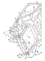
図3、図4に示すように、リアサイドフレーム16、リアエンドパネル18、およびリアエンドクロスメンバ19がリアガセット20で接続されている。リアガセット20は、
第1ガセット54と、第2ガセット55とを備えている。
第1ガセット54は、リアサイドフレーム16とリアエンドパネル18とに接続されている。第1ガセット54は、第1ガセット水平部57と、第1ガセット鉛直部58と、第1ガセット連結部59とを有する。第1ガセット水平部57の後端部に、第1ガセット連結部59を介して第1ガセット鉛直部58が連結されている。第1ガセット54は、第1ガセット水平部57、第1ガセット鉛直部58、および第1ガセット連結部59で断面L字状に形成されている。
As shown in FIGS. 3 and 4, the
A
The
第1ガセット水平部57は、リアサイドフレーム16のアッパメンバ31の後端部31aに沿って水平に配置されている。第1ガセット水平部57は、例えばアッパメンバ31の後端部31aにスポット溶接で接合されている。第1ガセット水平部57の両側部には車幅方向に間隔をおいて一対の水平ビード62(図5も参照)が形成されている。水平ビード62は、上方に隆起され、第1ガセット水平部57に沿って車体前後方向に延出されている。
The first gusset
第1ガセット鉛直部58は、リアエンドパネル18のうち、リアエンドクロスメンバ19の下側のパネル下方部位18cに沿って配置されている。第1ガセット鉛直部58は、例えばパネル下方部位18cにスポット溶接や、ボルト64、ナット65で接合されている。第1ガセット鉛直部58と第1ガセット水平部57とが第1ガセット連結部59で連結されている。
第1ガセット54は、リアサイドフレーム16とリアエンドパネル18とに接続されている。すなわち、リアサイドフレーム16のアッパメンバ31の後端部31aとリアエンドパネル18とが第1ガセット54により補強されている。
The first gusset
The
ここで、第1ガセット鉛直部58はパネル下方部位18cに接合されている。パネル下方部位18cは、リアエンドクロスメンバ19の下側の部位である。第1ガセット54は、リアエンドクロスメンバ19を避けて接合されている。よって、軽衝突によりリアサイドフレーム16の後端部16aに入力する衝撃荷重F1が第1ガセット54を経てリアエンドクロスメンバ19に伝達されることを抑制できる。
Here, the first gusset
これにより、リアサイドフレーム16の後端部16aに入力した衝撃荷重F1が第1ガセット54およびリアエンドクロスメンバ19を経てリアフェンダ39(図1参照)に伝達することを抑えることができる。
したがって、軽衝突によりリアサイドフレーム16の後端部16aに入力した衝撃荷重F1でリアフェンダ39が変形することを抑えることができる。このように、第1ガセット54は、後突により入力する衝撃荷重F1に対して主に寄与させることができる。
Thereby, it is possible to suppress the impact load F1 input to the
Therefore, it is possible to suppress the
第1ガセット54の上方に第2ガセット55が設けられている。第2ガセット55は、第1ガセット水平部57と、リアエンドクロスメンバ19の第1メンバ46とに接続されている。具体的には、第2ガセット55は、ガセット傾斜部71と、ガセット内壁部72と、ガセット外壁部73と、ガセットフランジ74とを備えている。
ガセット傾斜部71は、リアエンドクロスメンバ19の第1メンバ46から第1ガセット水平部57まで車体前方に向けて下り勾配に形成されている。ガセット傾斜部71は、傾斜上辺71aと、傾斜下辺71bと、傾斜内辺71cと、傾斜外辺71dとを有し、各辺71a〜71dで平面視矩形状に形成されている。
A
The gusset inclined
図5、図6に示すように、ガセット傾斜部71は、2つの縦ビード76と、開口部78とを有する。縦ビード76は、車体前方で、かつ上方に膨出され、傾斜内辺71cおよび傾斜外辺71dに沿って形成されている。すなわち、縦ビード76は、車幅方向に間隔L1をおいて配置されて、上下方向に傾斜状に延出されている。縦ビード76は、車幅方向への曲げに対して剛性が確保されている。
開口部78は、ガセット傾斜部71において、2つの縦ビード76間で、かつ、下半部71eに設けられている。開口部78は、例えば縦長の穴に形成されている。
As shown in FIGS. 5 and 6, the gusset inclined
In the gusset inclined
ガセット傾斜部71の傾斜内辺71cからガセット内壁部72が車体後方へ向けて折り曲げられている。ガセット内壁部72は、ガセット傾斜部71の傾斜内辺71c、第1内辺72a、第2内辺72bで側面視三角形状に形成されている。
ガセット傾斜部71の傾斜外辺71dからガセット外壁部73が車体後方へ向けて折り曲げられている。ガセット外壁部73は、ガセット傾斜部71の傾斜外辺71d、第1外辺73a、第2外辺73bで側面視三角形状に形成されている。
A gusset
A gusset
ガセット傾斜部71の傾斜上辺71aおよび傾斜下辺71b、ガセット内壁部72の第1内辺72aおよび第2内辺72b、ガセット外壁部73の第1外辺73aおよび第2外辺73bにガセットフランジ74が形成されている。
ガセットフランジ74は、第1フランジ81と、第2フランジ(フランジ)82とを有する。
第1フランジ81は、ガセット内壁部72の第2内辺72b、ガセット傾斜部71の傾斜上辺71a、ガセット外壁部73の第2外辺73bに沿って側面視U字状に形成されている。第1フランジ81は、ガセット傾斜部71の傾斜上辺71aに沿って形成されることにより、2つの縦ビード76の上端部76aを連結している。第1フランジ81は、一対の第1接合部83と、一対の第2接合部84とを有する。
The
The
一対の第1接合部83の一方は、第1フランジ81の車幅方向内側の下部で、縦ビード76の車体後方側に形成されている。一対の第1接合部83の他方は、第1フランジ81の車幅方向外側の下部で、縦ビード76の車体後方側に形成されている。すなわち、一対の第1接合部83は、車幅方向に間隔をおいて形成されている。
一対の第1接合部83は、第1ガセット鉛直部58に車体前方から重ねられている。一対の第1接合部83は、第1ガセット鉛直部58およびパネル下方部位18cに車幅方向へ間隔をおいて、例えばスポット溶接で接合されている。
One of the pair of first
The pair of first
一対の第2接合部84の一方は、第1フランジ81の車幅方向内側の上部に形成されている。一対の第2接合部84の他方は、第1フランジ81の車幅方向外側の上部に形成されている。
一対の第2接合部84は、リアエンドクロスメンバ19の左端部19aのうち、第1メンバ46に車体前方から重ねられている。一対の第2接合部84は、リアエンドクロスメンバ19の第1メンバ46に車体前後方向へ間隔をおいて、例えばスポット溶接で接合されている。
One of the pair of second
The pair of second
第1フランジ81の一対の第1接合部83に第2フランジ82が接続されている。第2フランジ82は、ガセット内壁部72の第1内辺72a、ガセット傾斜部71の傾斜下辺71b、ガセット外壁部73の第1外辺73aに沿って平面視U字状に形成されている。第2フランジ82は、ガセット傾斜部71の傾斜下辺71bに沿って形成されることにより、2つの縦ビード76の下端部76bを連結している。
A
図5、図7に示すように、第2フランジ82は、開口部78の下縁部(縁部)85を形成する。第2フランジ82は、開口部78の下縁部85の部位のみが第1ガセット水平部57に接触されている。第2フランジ82のうち、下縁部85を除いた離隔部位86は第1ガセット水平部57に対して上方に離隔されている。
第2フランジ82のうち、下縁部85は、第1ガセット水平部57およびリアサイドフレーム16のアッパメンバ31の後端部31aに、例えばスポット溶接で接合されている。
また、一対の第2接合部84は、リアエンドクロスメンバ19の第1メンバ46に車幅方向へ間隔をおいて、例えばスポット溶接で接合されている。
As shown in FIGS. 5 and 7, the
Of the
Further, the pair of second
すなわち、第1ガセット54の上方に第2ガセット55が配置され、リアサイドフレーム16とリアエンドクロスメンバ19とが第2ガセット55で接続されている。
さらに、2つの縦ビード76が車幅方向に間隔をおいて配置して上下方向に傾斜状に延出されている。縦ビード76は車幅方向への曲げに対して剛性が確保されている。
よって、車両Veの走行中に車幅方向へのねじり変形などが発生した際に、リアサイドフレーム16とリアエンドクロスメンバ19との相対変位を第2ガセット55で抑制できる。
That is, the
Further, two
Therefore, the relative displacement between the
加えて、一対の第1接合部83は、第1ガセット鉛直部58およびパネル下方部位18cに車幅方向へ間隔をおいて、例えばスポット溶接で接合されている。よって、車両Veの走行中に車幅方向へのねじり変形などが発生した際に、リアサイドフレーム16とリアエンドクロスメンバ19との相対変位を第2ガセット55で一層良好に抑制できる。
このように、第2ガセット55は、車両Veの走行中の車両剛性に対して主に寄与させることができる。
In addition, the pair of first
In this way, the
また、2つの縦ビード76間に開口部78が設けられている。第2ガセット55は、2つの縦ビード76間の剛性が開口部78で抑えられている。よって、車両Veの軽衝突によりリアサイドフレーム16の後端部16aに入力する衝撃荷重F1(図4参照)に対して、第2ガセット55の車体前後方向の剛性を抑えることができる。すなわち、リアサイドフレーム16の後端部16aに入力する衝撃荷重F1で第2ガセット55を車体前後方向に撓ませることができる。
これにより、リアサイドフレーム16の後端部16aに入力した衝撃荷重F1がリアエンドクロスメンバ19に沿って車幅方向に伝わることを抑制できる。
An
Thereby, it is possible to suppress the impact load F <b> 1 input to the
このように、第1ガセット54と第2ガセット55とを別部材とすることで、第1ガセット54と第2ガセット55との役割を分けることができる。これにより、車両Veの走行中に車幅方向へのねじり変形などが発生した際の剛性を高めることができ、さらに、リアフェンダ39(図1参照)の変形を抑えることができる。
Thus, the roles of the
また、2つの縦ビード76の下端部76b間が第2フランジ82で連結されている。よって、車幅方向へのねじり変形に対して第2ガセット55の剛性をより高めることができる。これにより、車両Veの走行中に車幅方向へのねじり変形などが発生した際に、リアサイドフレーム16とリアエンドクロスメンバ19との相対変位を一層抑制できる。
Further, the
さらに、第2ガセット55の一対の第1接合部83が車幅方向で第1ガセット鉛直部58およびリアエンドパネル18に接合されている。また、一対の第1接合部83に第2フランジ82が接続されている。
よって、一対の第1接合部83で第2フランジ82の剛性が高められている。すなわち、車幅方向へのねじり変形に対して第2ガセット55の剛性がより高められている。これにより、車両Veの走行中に車幅方向へのねじり変形などが発生した際に、リアサイドフレーム16とリアエンドクロスメンバ19との相対変位を一層抑制できる。
Further, the pair of first
Therefore, the rigidity of the
加えて、第2フランジ82のうち、開口部78の下縁部85のみが第1ガセット水平部57およびリアサイドフレーム16のアッパメンバ31に接合されている。よって、車両Veの軽衝突によりリアサイドフレーム16の後端部16aに入力する衝撃荷重F1(図4参照)に対して、第2ガセット55の車体前後方向の剛性が抑えられている。すなわち、リアサイドフレーム16の後端部16aに入力する衝撃荷重F1で第2ガセット55を車体前後方向に撓ませることができる。
これにより、リアサイドフレーム16の後端部16aに入力した衝撃荷重F1がリアエンドクロスメンバ19に沿って車幅方向に伝わることを抑制できる。
In addition, only the
Thereby, it is possible to suppress the impact load F <b> 1 input to the
また、開口部78の下縁部85が第1ガセット54に接合されている。よって、第2フランジ82の剛性が高められている。すなわち、車両Veの走行中に車幅方向へのねじり変形に対して第2ガセット55の剛性がより高められている。これにより、車両Veの走行中に車幅方向へのねじり変形などが発生した際に、リアサイドフレーム16とリアエンドクロスメンバ19との相対変位を一層抑制できる。
The
つぎに、第2実施形態の車体後部構造100を図8に基づいて説明する。第2実施形態の車体後部構造100において第1実施形態の車体後部構造12を同一、類似の構成部材については同じ符号を付して詳しい説明を省略する。
Next, the vehicle body
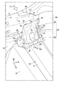
(第2実施形態)
図8に示すように、車体後部構造100は、第1実施形態の車体後部構造12から第1ガセット54を除去してガセット102を備えたもので、その他の構成は第1実施形態と同様である。
車体後部構造100は、リアエンドパネル18と、リアサイドフレーム16と、リアエンドクロスメンバ19と、ガセット102とを備えている。
リアサイドフレーム16とリアエンドパネル18とがガセット102で接続されている。また、リアサイドフレーム16とリアエンドクロスメンバ19とがガセット102で接続されている。
(Second Embodiment)
As shown in FIG. 8, the vehicle body
The vehicle body
The
ガセット102は、第1実施形態の第2ガセット55と同様に、ガセット傾斜部71と、ガセット内壁部72と、ガセット外壁部73と、ガセットフランジ74とを備えている。ガセットフランジ74は、第1フランジ81と、第2フランジ82とを有する。
第1フランジ81の一対の第1接合部83は、パネル下方部位18cに車幅方向へ間隔をおいて、例えばスポット溶接で接合されている。第1フランジ81の一対の第2接合部84は、リアエンドクロスメンバ19の第1メンバ46に車体前後方向へ間隔をおいて、例えばスポット溶接で接合されている。
第2フランジ82は、開口部78の下縁部85のみがリアサイドフレーム16のアッパメンバ31(具体的には、後端部31a)に、例えばスポット溶接で接合されている。
Similar to the
The pair of first
Only the
また、ガセット102は、第1実施形態の第2ガセット55と同様に、2つの縦ビード76が車幅方向に間隔をおいて配置され、上下方向に傾斜状に延出されている。
2つの縦ビード76は、車幅方向への曲げに対して剛性が確保されている。よって、車両Veの走行中に車幅方向へのねじり変形などが発生した際に、リアサイドフレーム16とリアエンドクロスメンバ19との相対変位を抑制できる。
Further, in the
The two
また、ガセット102は、第1実施形態の第2ガセット55と同様に、2つの縦ビード76間に開口部78が設けられている。よって、2つの縦ビード76間の剛性が開口部78で抑えられている。すなわち、リアサイドフレーム16の後端部16aに入力する衝撃荷重F2でガセット102を車体前後方向に撓ませることができる。
これにより、リアサイドフレーム16の後端部16aに入力した衝撃荷重F2がリアエンドクロスメンバ19に沿って車幅方向に伝わることを抑制できる。車両Veによる軽衝突によりリアサイドフレーム16の後端部16aに入力した衝撃荷重F2でリアフェンダ39(図2参照)が変形することを抑えることができる。
Further, the
Thereby, it is possible to suppress the impact load F <b> 2 input to the
また、2つの縦ビード76の下端部76b間が第2フランジ82で連結されている。よって、車幅方向へのねじり変形に対してガセット102の剛性をより高めることができる。これにより、車両Veの走行中に車幅方向へのねじり変形などが発生した際に、リアサイドフレーム16とリアエンドクロスメンバ19との相対変位を一層抑制できる。
Further, the
さらに、ガセット102の一対の第1接合部83が車幅方向でリアエンドパネル18に接合されている。また、一対の第1接合部83に第2フランジ82が接続されている。
よって、一対の第1接合部83で第2フランジ82の剛性が高められている。すなわち、車幅方向へのねじり変形に対してガセット102の剛性がより高められている。これにより、車両Veの走行中に車幅方向へのねじり変形などが発生した際に、リアサイドフレーム16とリアエンドクロスメンバ19との相対変位を一層抑制できる。
Further, the pair of first
Therefore, the rigidity of the
加えて、第2フランジ82のうち、開口部78の下縁部85のみがリアサイドフレーム16のアッパメンバ31に接合されている。よって、車両Veの軽衝突によりリアサイドフレーム16の後端部16aに入力する衝撃荷重F2に対して、ガセット102の車体前後方向の剛性が抑えられている。すなわち、リアサイドフレーム16の後端部16aに入力する衝撃荷重F2でガセット102を車体前後方向に撓ませることができる。
これにより、リアサイドフレーム16の後端部16aに入力した衝撃荷重F2がリアエンドクロスメンバ19に沿って車幅方向に伝わることを抑制できる。
In addition, only the
Thereby, it is possible to suppress the impact load F <b> 2 input to the
また、開口部78の下縁部85がガセット102に接合されている。よって、第2フランジ82の剛性が高められている。すなわち、車両Veの走行中に車幅方向へのねじり変形に対してガセット102の剛性がより高められている。これにより、車両Veの走行中に車幅方向へのねじり変形などが発生した際に、リアサイドフレーム16とリアエンドクロスメンバ19との相対変位を一層抑制できる。
The
なお、本発明の技術範囲は上述した実施形態に限定されるものではなく、本発明の趣旨を逸脱しない範囲において種々の変更を加えることが可能である。
例えば、前記実施形態では、ガセット傾斜部71の開口部78を縦ビード76間の下半部71eに形成した例について説明したが、これに限らない。その他の例として、開口部78を縦ビード76間の全域に形成することも可能である。また、開口部78を縦ビード76間の上半部に形成することも可能である。
The technical scope of the present invention is not limited to the above-described embodiments, and various modifications can be made without departing from the spirit of the present invention.
For example, in the above-described embodiment, the example in which the
また、前記実施形態では、開口部78を縦長の穴に形成した例について説明したが、開口部78の形状は任意に選択が可能である。また、開口部78を複数形成することも可能である。
Moreover, although the said embodiment demonstrated the example which formed the
さらに、前記実施形態では、第2ガセット55の2つの縦ビード76を車体前方で、かつ上方に膨出する例について説明したが、これに限定しない。その他の例として、縦ビード76を車体後方で、かつ下方に膨出させることも可能である。
Furthermore, although the said embodiment demonstrated the example which swells the two
10……車体
12,100…車体後部構造
16……リアサイドフレーム
18……リアエンドパネル
19……リアエンドクロスメンバ
20……リアガセット
54……第1ガセット
55……第2ガセット
76……縦ビード
78……開口部
82……第2フランジ(フランジ)
83……第1接合部
84……第2接合部
85……下縁部(縁部)
102…ガセット
10 …… Body 12,100 ...
83 …… First
102 ... Guset
Claims (8)
前記リアサイドフレームと前記リアエンドパネルとを接続する第1ガセットと、
前記第1ガセットとは別体で設けられ、前記第1ガセットの上方で前記リアサイドフレームと前記リアエンドクロスメンバとを接続する第2ガセットと、
を設けることを特徴とする車体後部構造。 A rear end panel, a rear side frame extending from the rear end panel toward the front of the vehicle body, and a rear end cross member extending in the vehicle width direction along the rear end panel and spaced apart from the rear side frame. Prepared,
A first gusset for connecting the rear side frame and the rear end panel;
A second gusset that is provided separately from the first gusset, and connects the rear side frame and the rear end cross member above the first gusset;
A vehicle body rear structure, characterized by comprising:
車幅方向に間隔をおいて配置されて上下方向に延びる2つの縦ビードと、
前記縦ビード間に設けられた開口部と、
を備えることを特徴とする請求項1に記載の車体後部構造。 The second gusset is
Two vertical beads arranged at intervals in the vehicle width direction and extending in the vertical direction;
An opening provided between the vertical beads;
The vehicle body rear structure according to claim 1, comprising:
前記縦ビード間を連結するフランジを備えることを特徴とする請求項2に記載の車体後部構造。 The second gusset is
The vehicle body rear structure according to claim 2, further comprising a flange that connects the vertical beads.
前記第1ガセットと車幅方向で接合される一対の第1接合部を備え、
前記フランジは、前記一対の第1接合部に接続されることを特徴とする請求項3に記載の車体後部構造。 The second gusset is
A pair of first joints joined to the first gusset in the vehicle width direction;
The vehicle body rear portion structure according to claim 3, wherein the flange is connected to the pair of first joint portions.
前記開口部の縁部を形成し、
該開口部の縁部のみで前記第1ガセットに上下方向から接合されることを特徴とする請求項3または請求項4に記載の車体後部構造。 The flange is
Forming an edge of the opening;
The vehicle body rear part structure according to claim 3 or 4, wherein the vehicle body rear part structure is joined to the first gusset from above and below only at an edge of the opening.
前記リアサイドフレームと前記リアエンドパネルとを接続する第1ガセットと、
前記第1ガセットの上方で前記リアサイドフレームと前記リアエンドクロスメンバとを接続する第2ガセットと、
を設け、
前記第2ガセットは、
前記第1ガセットと車幅方向で接合される一対の第1接合部を備えることを特徴とする車体後部構造。 A rear end panel, a rear side frame extending from the rear end panel toward the front of the vehicle body, and a rear end cross member extending in the vehicle width direction along the rear end panel and spaced apart from the rear side frame. Prepared,
A first gusset for connecting the rear side frame and the rear end panel;
A second gusset for connecting the rear side frame and the rear end cross member above the first gusset;
Provided ,
The second gusset is
Vehicle body rear portion structure according to claim Rukoto comprises a first junction of the pair being joined at said first gusset and the vehicle width direction.
前記リアサイドフレームと前記リアエンドクロスメンバとを接続するガセットを設け、
前記ガセットは、上下方向に延びる2つの縦ビードと、車幅方向の縦ビード間に設けられた開口部と、前記縦ビード間を連結するフランジと、を備え、
前記フランジは、
前記開口部の縁部を形成し、
該開口部の縁部のみで前記リアサイドフレームに上下方向から接合されることを特徴とする車体後部構造。 A rear end panel, a rear side frame extending from the rear end panel toward the front of the vehicle body, and a rear end cross member extending in the vehicle width direction along the rear end panel and spaced apart from the rear side frame. Prepared,
A gusset for connecting the rear side frame and the rear end cross member is provided,
The gusset includes two vertical beads extending in the vertical direction, an opening provided between the vertical beads in the vehicle width direction, and a flange connecting the vertical beads .
The flange is
Forming an edge of the opening;
A vehicle body rear portion structure that is joined to the rear side frame from above and below only at an edge of the opening .
前記リアエンドパネルと車幅方向で接合される一対の第1接合部を備え、
前記フランジは、前記一対の第1接合部に接続されることを特徴とする請求項7に記載の車体後部構造。 The gusset is
A pair of first joints joined to the rear end panel in the vehicle width direction;
The vehicle body rear portion structure according to claim 7, wherein the flange is connected to the pair of first joint portions.
Priority Applications (3)
| Application Number | Priority Date | Filing Date | Title |
|---|---|---|---|
| JP2017129319A JP6558779B2 (en) | 2017-06-30 | 2017-06-30 | Car body rear structure |
| US15/996,601 US10501125B2 (en) | 2017-06-30 | 2018-06-04 | Vehicle body rear portion structure |
| CN201810575371.0A CN109204554B (en) | 2017-06-30 | 2018-06-06 | Vehicle body rear structure |
Applications Claiming Priority (1)
| Application Number | Priority Date | Filing Date | Title |
|---|---|---|---|
| JP2017129319A JP6558779B2 (en) | 2017-06-30 | 2017-06-30 | Car body rear structure |
Publications (2)
| Publication Number | Publication Date |
|---|---|
| JP2019010987A JP2019010987A (en) | 2019-01-24 |
| JP6558779B2 true JP6558779B2 (en) | 2019-08-14 |
Family
ID=64735301
Family Applications (1)
| Application Number | Title | Priority Date | Filing Date |
|---|---|---|---|
| JP2017129319A Expired - Fee Related JP6558779B2 (en) | 2017-06-30 | 2017-06-30 | Car body rear structure |
Country Status (3)
| Country | Link |
|---|---|
| US (1) | US10501125B2 (en) |
| JP (1) | JP6558779B2 (en) |
| CN (1) | CN109204554B (en) |
Families Citing this family (2)
| Publication number | Priority date | Publication date | Assignee | Title |
|---|---|---|---|---|
| JP6881251B2 (en) * | 2017-11-21 | 2021-06-02 | トヨタ自動車株式会社 | Vehicle rear structure |
| CN112124442B (en) * | 2020-09-30 | 2022-05-31 | 安徽江淮汽车集团股份有限公司 | Connection structure, automobile and preparation method of connection structure |
Family Cites Families (10)
| Publication number | Priority date | Publication date | Assignee | Title |
|---|---|---|---|---|
| CN100358769C (en) * | 2003-10-07 | 2008-01-02 | 本田技研工业株式会社 | Vehicle rear body structure |
| JP2006088886A (en) | 2004-09-24 | 2006-04-06 | Honda Motor Co Ltd | Car body frame structure |
| JP4525276B2 (en) * | 2004-09-29 | 2010-08-18 | マツダ株式会社 | Lower body structure |
| US7568755B2 (en) * | 2007-03-23 | 2009-08-04 | Honda Motor Co., Ltd. | Rear frame structure for vehicle |
| DE102008020527A1 (en) * | 2008-04-24 | 2009-10-29 | GM Global Technology Operations, Inc., Detroit | Frame structure for a motor vehicle |
| CN104114438B (en) * | 2012-02-13 | 2016-09-21 | 本田技研工业株式会社 | Body bottom section constructs |
| JP6007643B2 (en) * | 2012-07-30 | 2016-10-12 | マツダ株式会社 | Upper body structure of the vehicle |
| KR101451159B1 (en) * | 2013-11-15 | 2014-10-15 | 현대자동차주식회사 | Structure for connecting wheel house panel to rear floor of vehicle |
| JP6511891B2 (en) * | 2015-03-19 | 2019-05-15 | トヨタ自動車株式会社 | Vehicle rear structure |
| JP6256429B2 (en) * | 2015-08-17 | 2018-01-10 | マツダ株式会社 | Vehicle body structure |
-
2017
- 2017-06-30 JP JP2017129319A patent/JP6558779B2/en not_active Expired - Fee Related
-
2018
- 2018-06-04 US US15/996,601 patent/US10501125B2/en active Active
- 2018-06-06 CN CN201810575371.0A patent/CN109204554B/en active Active
Also Published As
| Publication number | Publication date |
|---|---|
| JP2019010987A (en) | 2019-01-24 |
| US10501125B2 (en) | 2019-12-10 |
| CN109204554A (en) | 2019-01-15 |
| CN109204554B (en) | 2021-10-15 |
| US20190002031A1 (en) | 2019-01-03 |
Similar Documents
| Publication | Publication Date | Title |
|---|---|---|
| JP6462552B2 (en) | Body front structure | |
| JP6445953B2 (en) | Body front structure | |
| JP5907147B2 (en) | Lower body structure | |
| JP6546065B2 (en) | Front body structure | |
| JP4654917B2 (en) | Car body rear structure | |
| JP5776560B2 (en) | Auto body front structure | |
| JP5999134B2 (en) | Vehicle front structure | |
| JP6557290B2 (en) | Body front structure | |
| JP4996707B2 (en) | Car body side structure | |
| JP6264864B2 (en) | Vehicle lower structure | |
| JP6590862B2 (en) | Suspension arm support structure | |
| JP6059696B2 (en) | Body front structure | |
| JP6558779B2 (en) | Car body rear structure | |
| US10322753B2 (en) | Vehicle body front structure | |
| JP6272931B2 (en) | Body structure | |
| JP5202571B2 (en) | Car floor structure | |
| JP6155228B2 (en) | Bumper beam structure of vehicle | |
| JP6010230B2 (en) | Body front structure | |
| JP6044795B2 (en) | Front body structure of the vehicle | |
| JP2009143335A (en) | Joint structure for cowl side part | |
| JP6052231B2 (en) | Vehicle body structure | |
| JP5906920B2 (en) | Body structure | |
| JP7177814B2 (en) | Body front structure | |
| JP2019137352A (en) | Vehicle body structure | |
| JP7040380B2 (en) | Rear body structure of the vehicle |
Legal Events
| Date | Code | Title | Description |
|---|---|---|---|
| A131 | Notification of reasons for refusal |
Free format text: JAPANESE INTERMEDIATE CODE: A131 Effective date: 20181204 |
|
| A521 | Request for written amendment filed |
Free format text: JAPANESE INTERMEDIATE CODE: A523 Effective date: 20190122 |
|
| TRDD | Decision of grant or rejection written | ||
| A01 | Written decision to grant a patent or to grant a registration (utility model) |
Free format text: JAPANESE INTERMEDIATE CODE: A01 Effective date: 20190618 |
|
| A61 | First payment of annual fees (during grant procedure) |
Free format text: JAPANESE INTERMEDIATE CODE: A61 Effective date: 20190710 |
|
| R150 | Certificate of patent or registration of utility model |
Ref document number: 6558779 Country of ref document: JP Free format text: JAPANESE INTERMEDIATE CODE: R150 |
|
| LAPS | Cancellation because of no payment of annual fees |