JP2006306135A - Rear bodywork of vehicle - Google Patents
Rear bodywork of vehicle Download PDFInfo
- Publication number
- JP2006306135A JP2006306135A JP2005127796A JP2005127796A JP2006306135A JP 2006306135 A JP2006306135 A JP 2006306135A JP 2005127796 A JP2005127796 A JP 2005127796A JP 2005127796 A JP2005127796 A JP 2005127796A JP 2006306135 A JP2006306135 A JP 2006306135A
- Authority
- JP
- Japan
- Prior art keywords
- joined
- side frame
- wheel house
- floor panel
- vehicle
- Prior art date
- Legal status (The legal status is an assumption and is not a legal conclusion. Google has not performed a legal analysis and makes no representation as to the accuracy of the status listed.)
- Granted
Links
Images


Abstract
Description
本発明は、車両の後部車体構造に関し、特にホイルハウスとフロアパネルとサイドフレームの結合部の剛性・強度を補強ガセットにより向上させたものに関する。 The present invention relates to a rear body structure of a vehicle, and more particularly to a structure in which the rigidity and strength of a joint portion of a wheel house, a floor panel, and a side frame are improved by a reinforcing gusset.
車両の後輪用のホイルハウスにサスペンションのダンパーを支持するダンパー支持部(別名、サスタワー)が設けられ、後輪に作用する大きな荷重がダンパー支持部に作用する。ホイルハウスの付近のサイドフレームには、サスペンション装置のサスクロスメンバが連結されるため、サスクロスメンバからもサイドフレームやホイルハウスに大きな荷重が作用する。そこで、ダンパー支持部やホイルハウスなどを補強する種々の補強ガセットや補強構造が設けられている。 A wheel support for the rear wheel of the vehicle is provided with a damper support portion (also called a suspension tower) that supports the damper of the suspension, and a large load acting on the rear wheel acts on the damper support portion. Since the suspension cross member of the suspension device is connected to the side frame in the vicinity of the wheel house, a large load acts on the side frame and the wheel house from the suspension cross member. Therefore, various reinforcing gussets and reinforcing structures for reinforcing the damper support portion and the wheel house are provided.
一般に、ホイルハウスに、サイドフレームの接合フランジと、フロアパネルの外端部とが3枚重ねの構造で接合されるが、前記のような補強ガセットを追加的に接合する場合には、4枚以上の板部材をスポット溶接する個所が発生する。しかし、3枚を超える板部材をスポット溶接する接合部では、その溶接品質を確保することが難しく、車両の長期の使用中に接合部に剥離が発生する確率が高くなる。
特許文献1には、リヤフロアの取付け構造において、ホイルハウスにフロアパネルの外端部を接合する内側角部に前後方向の所定長さ範囲に亙る補強部材を追加的に設ける技術が記載されている。
Patent Document 1 describes a technique of additionally providing a reinforcing member over a predetermined length range in the front-rear direction at an inner corner where the outer end of a floor panel is joined to a wheel house in a rear floor mounting structure. .
前記特許文献1の図2のリヤフロアの取付け構造では、サイドフレームの外側約半幅分について補強部材で補強するだけであるので、サイドフレームの内側約半幅分については薄いフロアパネル1枚の構造となるため、ホイルハウスとサイドフレームとの結合部を十分に強化することが難しい。そこで、前記の補強部材の幅を拡大することも可能であるが、その場合、補強部材として採用する板部材は約1.0mm程度の板厚のものとなるが、フロアパネルの板厚と補強部材の板厚との合計板厚は過大な板厚となり、部材数も増すため、製作費と重量増加の面で不利である。 In the rear floor mounting structure shown in FIG. 2 of the above-mentioned Patent Document 1, since only the outer half width of the side frame is reinforced by the reinforcing member, the inner half width of the side frame is a thin floor panel. Therefore, it is difficult to sufficiently strengthen the joint between the wheel house and the side frame. Therefore, it is possible to enlarge the width of the reinforcing member. In this case, the plate member employed as the reinforcing member has a thickness of about 1.0 mm. The total plate thickness with the plate thickness of the members becomes an excessive plate thickness and the number of members increases, which is disadvantageous in terms of production cost and weight increase.
他方、サスペンション装置のサスクロスメンバを車体に連結するためのサスクロス取付けボルトは、サイドフレームに装備してサイドフレームから下方へ延ばすのが普通であり、このサスクロス取付けボルトの上端部と上下方向の途中部がサイドフレームに溶接接合されるが、上記の上下の溶接接合部間の間隔は、サイドフレームの深さ寸法の制約を受けるため、その間隔を拡大してサスクロス取付けボルトをサイドフレームに固定支持する支持剛性を高めることは簡単ではない。 On the other hand, the suspension cross mounting bolt for connecting the suspension cross member of the suspension device to the vehicle body is usually provided on the side frame and extended downward from the side frame. The part is welded to the side frame, but the distance between the upper and lower welded joints is restricted by the depth dimension of the side frame. It is not easy to increase the supporting rigidity.
本発明の目的は、ホイルハウスとフロアパネルとサイドフレームの結合部の剛性・強度を簡単な構造で高めること、サスクロス取付けボルトをサイドフレームに支持する支持剛性を高めることなどである。 An object of the present invention is to increase the rigidity / strength of the connecting portion of the wheel house, the floor panel, and the side frame with a simple structure, and to increase the support rigidity for supporting the suspension cross mounting bolt on the side frame.
請求項1の車両の後部車体構造は、前後方向に延びるサイドフレームの車幅方向外端部がホイルハウスに接合され且つフロアパネルがサイドフレームに接合される車両の車体後部構造において、フロアパネルよりも板厚が厚く形成された補強ガセットであって、車幅方向内端部がサイドフレームの内端の水平フランジ部に接合される水平板部と、水平板部の外端部からホイルハウスの車幅方向内面に沿うように延びるフランジ部とを備え、このフランジ部がサイドフレームの外端部とホイルハウスとに接合される補強ガセットを設け、ホイルハウス近傍におけるフロアパネルの外端部が補強ガセットの内端部に接合されたことを特徴とするものである。 The rear vehicle body structure of the vehicle according to claim 1 is a vehicle body rear structure in which a vehicle frame width direction outer end portion of a side frame extending in the front-rear direction is joined to a wheel house and a floor panel is joined to the side frame. The reinforcing gusset is also formed with a thick plate thickness, and the inner end of the vehicle width direction is joined to the horizontal flange portion of the inner end of the side frame, and the outer end of the horizontal plate portion And a flange portion extending along the inner surface in the vehicle width direction. The flange portion is provided with a reinforcing gusset that is joined to the outer end portion of the side frame and the wheel house, and the outer end portion of the floor panel in the vicinity of the wheel house is reinforced. It is characterized by being joined to the inner end of the gusset.
この請求項1の発明では、フロアパネルよりも厚い板厚の補強ガセットをサイドフレームの内端水平フランジからホイルハウスに亙って設けるため、ホイルハウスとフロアパネルとサイドフレームとの結合部の強度・剛性を高めることができる。
補強ガセットの大部分は、フロアパネルを兼用するものとして設けられ、フロアパネルと重複しないため、補強ガセットとして最適の板厚を有するものを採用できるから、フロアパネルと重複して過大な板厚となるのを確実に防止することができる。
According to the first aspect of the present invention, since the reinforcing gusset having a thickness greater than that of the floor panel is provided from the inner side horizontal flange of the side frame to the wheel house, the strength of the joint portion between the wheel house, the floor panel, and the side frame is provided.・ The rigidity can be increased.
Most of the reinforced gusset is provided as a floor panel and does not overlap with the floor panel, so it can be used as the reinforced gusset with the optimal thickness. Can be reliably prevented.
請求項2の車両の後部車体構造は、請求項1の発明において、前記ホイルハウスにサスペンションのダンパーを支持するダンパー支持部が設けられ、このダンパー支持部に近接する補強ガセットの水平板部とフランジ部にわたる部分に車室側へ膨出する膨出部を形成したことを特徴とするものである。
The rear vehicle body structure of the vehicle according to
請求項3の車両の後部車体構造は、請求項2の発明において、前記サイドフレーム内に側面視ハット形のブラケットを設け、このブラケット上壁部及びサイドフレーム下壁に固定支持されるサスクロス取付けボルトが設けられ、このサスクロス取付けボルトの上端部を前記膨出部内に配設することを特徴とするものである。 According to a third aspect of the present invention, there is provided a vehicle body structure for a rear portion of the vehicle according to the second aspect of the present invention, wherein the side frame is provided with a hat-shaped bracket in a side view and is fixedly supported by the bracket upper wall portion and the side frame lower wall. And an upper end portion of the suspension cross mounting bolt is disposed in the bulging portion.
請求項4の車両の後部車体構造は、前記左右のホイルハウス間において左右のサイドフレーム間に橋渡し状に架設されてフロアパネルに接合されるクロスメンバが設けられ、補強ガセットの内端部の一部がクロスメンバに接合されることを特徴とするものである。
The vehicle rear body structure according to
請求項5の車両の後部車体構造は、請求項1〜4の何れかの発明において、前記補強ガセットの前端がホイルハウス部前方のドア開口部後端付近まで延びることを特徴とするものである。
The rear vehicle body structure of the vehicle according to
請求項1の発明によれば、フロアパネルよりも厚い板厚の補強ガセットをサイドフレームの内端水平フランジからホイルハウスに亙って設けるため、ホイルハウスとフロアパネルとサイドフレームとの結合部の強度・剛性を高めることができる。
補強ガセットの大部分は、フロアパネルを兼用するものとして設けられ、フロアパネルと重複しない構造にするため、補強ガセットとして最適の板厚を有するものを採用できるから、フロアパネルと重複して過大な板厚となるのを確実に防止することができ、重量増加や製作費の増加も僅かで済む。
According to the first aspect of the present invention, since the reinforcing gusset having a thickness greater than that of the floor panel is provided from the inner end horizontal flange of the side frame to the wheel house, the connecting portion between the wheel house, the floor panel, and the side frame is provided. Strength and rigidity can be increased.
Most of the reinforced gusset is provided as a floor panel, and it has a structure that does not overlap with the floor panel. It is possible to reliably prevent the plate thickness, and only a slight increase in weight and production cost are required.
請求項2の発明によれば、ホイルハウスにサスペンションのダンパーを支持するダンパー支持部が設けられ、このダンパー支持部に近接する補強ガセットの水平板部とフランジ部にわたる部分に車室側へ膨出する膨出部を形成したので、ホイルハウスとフロアパネルとサイドフレームとの結合部の強度・剛性を高めることができるうえ、補強用部材の部品点数と重量を増すことなく、ダンパー支持部近傍のホイルハウスとフロアパネルにかけて要求される強度・剛性を確保することができる。
According to the invention of
請求項3の発明によれば、サイドフレーム内に側面視ハット形のブラケットを設け、このブラケット上壁部及びサイドフレーム下壁に固定支持されるサスクロス取付けボルトが設けられ、このサスクロス取付けボルトの上端部を前記膨出部内に配設するため、サスクロス取付けボルトをサイドフレームに固定支持する上下の支持点間の間隔を大きくすることできるから、サスクロス取付けボルトの支持剛性を高めることができる。 According to the third aspect of the present invention, the side-view hat-shaped bracket is provided in the side frame, the suspension cross mounting bolt fixedly supported by the bracket upper wall portion and the side frame lower wall is provided, and the upper end of the suspension cross mounting bolt is provided. Since the portion is disposed in the bulging portion, the distance between the upper and lower support points for fixing and supporting the suspension cross mounting bolt to the side frame can be increased, so that the support rigidity of the suspension cross mounting bolt can be increased.
請求項4の発明によれば、左右のホイルハウス間において左右のサイドフレーム間に橋渡し状に架設されてフロアパネルに接合されるクロスメンバが設けられ、補強ガセットの内端部の一部がクロスメンバに接合されるため、補強ガセットとクロスメンバの結合を強化し、後部車体の剛性を向上できる。
According to the invention of
請求項5の発明によれば、補強ガセットの前端がホイルハウス部前方のドア開口部後端付近まで延びているため、ドア開口部の近傍におけるホイルハウスの剛性を高め、溶接接合部に剥離が生じたりするのを防止することできる。
According to the invention of
本発明に係る車両の車体後部構造は、フロアパネルよりも板厚が厚く形成された補強ガセットであって、車幅方向内端部がサイドフレームの内端の水平フランジ部に接合される水平板部と、水平板部の外端部からホイルハウスの車幅方向内面に沿うように延びるフランジ部とを備え、このフランジ部がサイドフレームの外端部とホイルハウスとに接合される補強ガセットを設け、ホイルハウス近傍におけるフロアパネルの外端部が補強ガセットの内端部に接合されたことを特徴とするものである。 The vehicle body rear structure according to the present invention is a reinforcing gusset having a plate thickness thicker than that of the floor panel, and a horizontal plate whose inner end in the vehicle width direction is joined to a horizontal flange at the inner end of the side frame. And a flange portion that extends from the outer end portion of the horizontal plate portion along the inner surface in the vehicle width direction of the wheel house, and a reinforcing gusset that is joined to the outer end portion of the side frame and the wheel house. The outer end of the floor panel in the vicinity of the wheel house is joined to the inner end of the reinforcing gusset.
以下、この車両の車体後部構造について図面に基づいて説明する。
本実施例は、ワゴン型自動車 の後部車体構造に本発明を適用した場合の一例であり、以下、このワゴン型自動車における前後左右を前後左右とし、車幅方向に関して車室中心側を内方、車室中心に対して遠のく方向を外方として説明する。
Hereinafter, the rear body structure of the vehicle will be described with reference to the drawings.
This embodiment is an example of the case where the present invention is applied to the rear body structure of a wagon-type automobile. Hereinafter, the front-rear and left-right directions of the wagon-type automobile are referred to as front-rear, left-right, and the center side of the vehicle compartment in the vehicle width direction is inward. The direction far from the center of the passenger compartment will be described as outward.
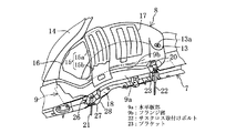
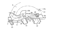
図1〜図6に示すように、ワゴン型自動車1の後部車体構造は、左右対称の構造であるので右側の車体構造について説明する。この後部車体構造は、後部ドア用のドア開口部2、側部車体パネル3、バックドア用のドア開口部4、サイドシル5、フロアパネル6、このフロアパネル6の右端部分の下面側に配設されて前後方向に延びるサイドフレーム7、後輪用のホイルハウス8、補強ガセット9、フロアパネル6と協働して閉断面を形成するクロスメンバ10〜12などが設けられている。尚、図4 はフロアパネル6を取り除いた状態を示す斜視図である。
As shown in FIGS. 1 to 6, the rear body structure of the wagon-type vehicle 1 is a symmetrical structure, and therefore the right-side body structure will be described. This rear body structure is arranged on the lower surface side of the right end portion of the
ホイルハウス8の後端部には、後輪サスペンション装置のダンパー(図示略)の頂部が支持されるダンパー支持部13が形成され、このダンパー支持部13にはダンパーの軸部材の上端部を挿入する軸穴13aが形成されている。ホイルハウス8の前部には、ドア開口部2の後端側ピラー部14を補強すると共にホイルハウス8を補強する補強板15が設けられている。この補強板15の上端部は後端側ピラー部14の付近まで延び、補強板15の下端部は補強ガセット9の上面に接合されている。
A
図1、図3に示すように、この補強板15は上部側板部材15aと下部側板部材15bとを溶接接合して構成され、下部側板部材15bはホイルハウス8とフロアパネル6とで閉断面を構成している。但し、補強板15は1枚の板部材で構成してもよい。その他にホイルハウス8には、補強板15よりも前側部分を補強する補強板16と、補強板15よりも後側部分を補強する補強板17が接合されている。
As shown in FIGS. 1 and 3, the
図3〜図6に示すように、サイドフレーム7は、溝形断面のフレーム本体7aと、車幅方向外端の外端フランジ7bと、車幅方向内端の内端水平フランジ7cとを有し、外端フランジ7bが立向きに形成されてホイルハウス8の車室側内面に接合されている。ホイルハウス8の前部に対応する位置には、フロアパネル6が後方上がりに傾斜する傾斜フロア部があり、サイドフレーム7には、その傾斜フロア部に対応するように後方上がりに傾斜するキックアップ部18が形成されている(図2参照)。そして、図6に示すように、補強板15に対応する部位であって、クロスメンバ11が接合されるサイドフレーム7の部位において、そのフレーム本体7aには、断面U形の補強フレーム19が接合され補強されている。
As shown in FIGS. 3 to 6, the
補強ガセット9は、主に、ホイルハウス8とフロアパネル6とサイドフレーム7の結合構造を補強する為の板部材であり、フロアパネル6(例えば板厚0.6mm)よりも厚い板厚(例えば1.8mm)の板材で構成されている。
この補強ガセット9は、車幅方向内端部がサイドフレーム7の内端水平フランジ部7cに接合される水平板部9aと、この水平板部9aの外端部からホイルハウス8の内面に沿うように一体的に延びるほぼ立て向きのフランジ部9bとを備えている。
The reinforcing
The reinforcing
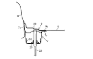
水平板部9aの内端部9cがサイドフレーム7の内端水平フランジ7cの上面に接合され、この水平板部9aの内端部9cの上面にフロアパネル6の外端部6cが重ねて接合される。このフランジ部9bがサイドフレーム7の外端フランジ7bとホイルハウス8とに接合されている。但し、図5に示すように、後述の膨出部20の部分においてはフランジ部9bがサイドフレーム7の外端フランジ7bに接合されていないが、外端フランジ7bに接合してもよい。
The
この補強ガセット9は、ホイルハウス8とほぼ同じ前後長に形成され、ホイルハウス8の前端よりやや前方の部位であって、 ドア開口部2の後端付近からホイルハウス8の後端付近までの前後長を有し、車幅方向についてはホイルハウス8からサイドフレーム7の内端水平フランジ7cの内端よりもやや内側までの範囲に亙っている。
The reinforcing
図4に示すように、補強ガセット9の大部分は、フロアパネル6を兼ねる補強板部材として構成され、補強ガセット9の上面に記載の二点鎖線Lは、フロアパネル6の端縁を示す線であり、補強ガセット9の前端部分9dと後端部分9eと内端部9cにはフロアパネル6の一部が上方から重ねて接合され、ホイルハウス8近傍におけるフロアパネル6の外端部6cが補強ガセット9の内端部9cの上面に接合されている。
As shown in FIG. 4, most of the reinforcing
図2、図3、図5に示すように、補強ガセット9のうちのダンパー支持部13に近接する後端寄り部分において、補強ガセット9の水平板部9aとフランジ部9bにわたる部分に車室側へ3段階状に膨出する膨出部20であって、フロアパネル6よりも上方へ膨らんだ膨出部20が形成されている。後輪サスペンションを取付ける為のサスペンションクロスメンバ(図示略)を車体に取付ける為の立向きの前後1対のサスクロス取付けボルト21,22が設けられている(図2参照)。
As shown in FIGS. 2, 3, and 5, in the portion near the rear end of the reinforcing
図2、図5に示すように、後側のサスクロス取付けボルト22を取付ける構造について、補強ガセット9の膨出部20の下方において、サイドフレーム7のフレーム本体7a内に側面視ハット形のブラケット23が設けられ、このブラケット23の下端部の前後1対のフランジ部がフレーム本体7aの下壁に接合されている。サスクロス取付けボルト22は、ブラケット23の上壁部及びサイドフレーム7のフレーム本体7aの下壁を立向きに貫通してサイドフレーム7の下方へ延びている。このサスクロス取付けボルト22の上端部(頭部)が膨出部20内に配設され、サスクロス取付けボルト22の上端部がブラケット23の上壁部に溶接にて固定され、サスクロス取付けボルト22の上下方向の途中部がサイドフレーム7のフレーム本体7aの下壁に溶接にて固定されている。
As shown in FIG. 2 and FIG. 5, in the structure for attaching the rear suspension
このサスクロス取付けボルト22をフレーム本体7aの下壁で支持する部分を強化するため、また、クロスメンバ12がサイドフレーム7に接合される部分を強化するため、フレーム本体7aの下部には、サスクロス取付けボルト22が貫通するU形の補強板24が内面に密着状に接合され、この補強板24にはサスクロス取付けボルト22が貫通する環状補強部材25が溶接にて接合され、サスクロス取付けボルト22は補強板24にも溶接接合されている(図5参照)。
In order to reinforce the portion where the suspension
図2に示すように、前側のサスクロス取付けボルト21を取付ける為、サイドフレーム7のキックアップ部18の前端付近において、サイドフレーム7のフレーム本体7a内に側面視ほぼハット形のブラケット26が設けられ、このブラケット26がフレーム本体7aに接合され、サスクロス取付けボルト21は、ブラケット26の上壁部及びサイドフレーム7のフレーム本体7aの下壁とこの下壁の上面に溶接にて固定された環状補強部材27を貫通させて立向きにサイドフレーム7の下方へ延びるように配設され、サスクロス取付けボルト21の上端部がブラケット26の上壁部に溶接にて接合され、サスクロス取付けボルト21の上下方向途中部がフレーム本体7aの下壁に溶接にて接合されている。尚、サイドフレーム7のキックアップ部18を補強する補強部材28も接合されている。
As shown in FIG. 2, a
左右のホイルハウス8の前端部よりもやや前側において、左右のサイドフレーム7間に橋渡し状に架設されてフロアパネル6に接合されるクロスメンバ10が設けられている。 また、左右のホイルハウス8間において左右のサイドフレーム7間に橋渡し状に架設されてフロアパネル6に接合されるクロスメンバ11,12が設けられ、補強ガセット9の内端部の一部がクロスメンバ11,12の上端部のフランジに接合される(図6参照)。
A
以上説明した後部車体構造の作用、効果について説明する。
フロアパネル6よりも厚い板厚の補強ガセット9をサイドフレーム7の内端水平フランジ7cからホイルハウス8に亙って設けるため、ホイルハウス8とフロアパネル6とサイドフレーム7との結合部の強度・剛性を高めることができる。
The operation and effect of the rear vehicle body structure described above will be described.
Since the reinforcing
補強ガセット9の大部分は、フロアパネル6を兼用するものとして設けられ、フロアパネル6と重複しないため、補強ガセット9として最適の板厚のものを選択して採用できるから、フロアパネル6と重複して過大な板厚となるのを確実に防止することができる。そして、補強ガセット9を追加する分、フロアパネル6の一部を省略することができるため、車体組み立ての生産性が低下することもない。
Most of the reinforcing
ホイルハウス8にサスペンション装置のダンパーを支持するダンパー支持部13が設けられ、このダンパー支持部13に近接する補強ガセット9の水平板部9aとフランジ部9bにわたる部分に車室側へ膨出する膨出部20を形成したので、ホイルハウス8とフロアパネル6とサイドフレーム7との結合部の強度・剛性を高めることができるうえ、補強用部材の部品点数と重量を増すことなく、ダンパー支持部13の近傍のホイルハウス8とフロアパネル6にかけて要求される強度・剛性を確保することができる。
The
サイドフレーム7内に側面視ハット形のブラケット23を設け、このブラケット23の上壁部及びサイドフレーム7の下壁に固定支持されるサスクロス取付けボルト22が設けられ、このサスクロス取付けボルト22の上端部を膨出部20内に配設するため、サスクロス取付けボルト22をサイドフレーム7に固定支持する上下の支持点間の間隔を大きくすることできるから、サスクロス取付けボルト22の支持剛性を高めることができる。
A side-view hat-shaped
左右のホイルハウス8間において左右のサイドフレーム7間に橋渡し状に架設されてフロアパネル6に接合されるクロスメンバ11,12が設けられ、補強ガセット9の内端部の一部がクロスメンバ11,12のフランジ部に接合されるため、補強ガセット9とクロスメンバ11,12の結合を強化し、後部車体の剛性を向上できる。
補強ガセット9の前端がホイルハウス8の前方のドア開口部2の後端付近まで延びているため、ドア開口部2の近傍におけるホイルハウス8の剛性を高め、溶接接合部に剥離が生じたりするのを防止することできる。しかも、補強ガセット9の大部分は、フロアパネル6を兼ねる板部材であるため、フロアパネル6や補強ガセット9と、ホイルハウス8及びサイドフレーム7などを接合する部位を3枚以下の板部材の接合とし、4枚接合となるのを確実に防止し、接合部の溶接品質を確保することもできる。
Since the front end of the reinforcing
しかも、補強ガセット9の前端部分9d、後端部分9f、内端部9cのうえにフロアパネル6を密着状に重ねて接合するため、ホイルハウス8の前端付近と後端付近におけるフロアパネル6と補強ガセット9との結合を強化し、フロア構造の剛性と強度を高め、ホイルハウス8とフロアパネル6を結合する部位の剛性を高めることができる。
In addition, since the
尚、当業者であれば、本発明の趣旨を逸脱しない範囲で、前記実施例に部分的な変更を付加した形で実施することもある。例えば、補強ガセット9のフランジ部9bの上下幅を大きく形成したり、補強ガセット9の前端部分9dや後端部分9eに重なるフロアパネル6のラップ幅を少なくしたり、補強ガセット9の水平板部9aの断面形状を適宜変更したり、補強ガセット9を板厚の異なる2枚以上の板部材を接合した板部材で構成したり、補強ガセット9の前後長を拡大したり、などの種々の変更はあり得る。
It should be noted that those skilled in the art may implement the above-described embodiment with partial modifications without departing from the spirit of the present invention. For example, the
2 ドア開口部
6 フロアパネル
7 サイドフレーム
7b 外端フランジ
7c 内端水平フランジ
8 ホイルハウス
9 補強ガセット
9a 水平板部
9b フランジ部
11 クロスメンバ
13 ダンパー支持部
20 膨出部
22 サスクロス取付けボルト
23 ブラケット
2
7c Inner end
Claims (5)
フロアパネルよりも板厚が厚く形成された補強ガセットであって、車幅方向内端部がサイドフレームの内端の水平フランジ部に接合される水平板部と、水平板部の外端部からホイルハウスの車幅方向内面に沿うように延びるフランジ部とを備え、このフランジ部がサイドフレームの外端部とホイルハウスとに接合される補強ガセットを設け、
ホイルハウス近傍におけるフロアパネルの外端部が補強ガセットの内端部に接合された ことを特徴とする車両の後部車体構造。 In the vehicle rear body structure in which the vehicle frame direction outer end portion of the side frame extending in the front-rear direction is joined to the wheel house and the floor panel is joined to the side frame,
Reinforcing gussets that are thicker than the floor panel, with the inner end in the vehicle width direction joined to the horizontal flange at the inner end of the side frame, and the outer end of the horizontal plate A flange portion extending along the inner surface in the vehicle width direction of the wheel house, and a reinforcing gusset that is joined to the outer end portion of the side frame and the wheel house is provided.
A rear body structure of a vehicle, characterized in that the outer end of the floor panel in the vicinity of the wheel house is joined to the inner end of the reinforcing gusset.
The rear body structure of the vehicle according to any one of claims 1 to 4, wherein a front end of the reinforcing gusset extends to a vicinity of a rear end of a door opening in front of the wheel house portion.
Priority Applications (1)
| Application Number | Priority Date | Filing Date | Title |
|---|---|---|---|
| JP2005127796A JP4696664B2 (en) | 2005-04-26 | 2005-04-26 | Rear body structure of the vehicle |
Applications Claiming Priority (1)
| Application Number | Priority Date | Filing Date | Title |
|---|---|---|---|
| JP2005127796A JP4696664B2 (en) | 2005-04-26 | 2005-04-26 | Rear body structure of the vehicle |
Publications (2)
| Publication Number | Publication Date |
|---|---|
| JP2006306135A true JP2006306135A (en) | 2006-11-09 |
| JP4696664B2 JP4696664B2 (en) | 2011-06-08 |
Family
ID=37473533
Family Applications (1)
| Application Number | Title | Priority Date | Filing Date |
|---|---|---|---|
| JP2005127796A Expired - Fee Related JP4696664B2 (en) | 2005-04-26 | 2005-04-26 | Rear body structure of the vehicle |
Country Status (1)
| Country | Link |
|---|---|
| JP (1) | JP4696664B2 (en) |
Cited By (5)
| Publication number | Priority date | Publication date | Assignee | Title |
|---|---|---|---|---|
| DE102012015538A1 (en) | 2011-08-31 | 2013-02-28 | Mazda Motor Corp. | Vehicle body structure and manufacturing method thereof |
| CN103057596A (en) * | 2013-01-18 | 2013-04-24 | 浙江吉利汽车研究院有限公司杭州分公司 | Reinforced connecting structure of side wall assembly and bottom assembly of automobile |
| CN107010123A (en) * | 2015-11-13 | 2017-08-04 | 丰田自动车株式会社 | Wheel cover structure |
| CN109823401A (en) * | 2017-11-23 | 2019-05-31 | 上汽通用五菱汽车股份有限公司 | A kind of mounting assembly of independent rear suspension |
| CN114655317A (en) * | 2022-04-22 | 2022-06-24 | 重庆长安汽车股份有限公司 | Rear wheel bulge inner panel mounting structure |
Citations (10)
| Publication number | Priority date | Publication date | Assignee | Title |
|---|---|---|---|---|
| JPS54130209U (en) * | 1978-03-01 | 1979-09-10 | ||
| JPS6244783U (en) * | 1985-09-09 | 1987-03-18 | ||
| JPS6278584U (en) * | 1985-11-06 | 1987-05-20 | ||
| JPH01138870U (en) * | 1988-03-18 | 1989-09-21 | ||
| JPH0338289U (en) * | 1989-08-25 | 1991-04-12 | ||
| JPH0446874A (en) * | 1990-06-12 | 1992-02-17 | Nissan Motor Co Ltd | Suspension installation part structure for automobile |
| JPH0441471U (en) * | 1990-08-07 | 1992-04-08 | ||
| JPH06166385A (en) * | 1992-11-30 | 1994-06-14 | Suzuki Motor Corp | Fitting structure or rear floor |
| JPH074263U (en) * | 1993-06-17 | 1995-01-20 | 富士重工業株式会社 | Vehicle rear suspension mounting structure |
| JP2003212152A (en) * | 2002-01-22 | 2003-07-30 | Mitsubishi Motors Corp | Vehicle body structure |
-
2005
- 2005-04-26 JP JP2005127796A patent/JP4696664B2/en not_active Expired - Fee Related
Patent Citations (10)
| Publication number | Priority date | Publication date | Assignee | Title |
|---|---|---|---|---|
| JPS54130209U (en) * | 1978-03-01 | 1979-09-10 | ||
| JPS6244783U (en) * | 1985-09-09 | 1987-03-18 | ||
| JPS6278584U (en) * | 1985-11-06 | 1987-05-20 | ||
| JPH01138870U (en) * | 1988-03-18 | 1989-09-21 | ||
| JPH0338289U (en) * | 1989-08-25 | 1991-04-12 | ||
| JPH0446874A (en) * | 1990-06-12 | 1992-02-17 | Nissan Motor Co Ltd | Suspension installation part structure for automobile |
| JPH0441471U (en) * | 1990-08-07 | 1992-04-08 | ||
| JPH06166385A (en) * | 1992-11-30 | 1994-06-14 | Suzuki Motor Corp | Fitting structure or rear floor |
| JPH074263U (en) * | 1993-06-17 | 1995-01-20 | 富士重工業株式会社 | Vehicle rear suspension mounting structure |
| JP2003212152A (en) * | 2002-01-22 | 2003-07-30 | Mitsubishi Motors Corp | Vehicle body structure |
Cited By (13)
| Publication number | Priority date | Publication date | Assignee | Title |
|---|---|---|---|---|
| DE102012015538A1 (en) | 2011-08-31 | 2013-02-28 | Mazda Motor Corp. | Vehicle body structure and manufacturing method thereof |
| CN102963433A (en) * | 2011-08-31 | 2013-03-13 | 马自达汽车株式会社 | Vehicle-body structure of vehicle and manufacturing method of the same |
| JP2013049379A (en) * | 2011-08-31 | 2013-03-14 | Mazda Motor Corp | Vehicle body structure of vehicle and manufacturing method thereof |
| DE102012015538B4 (en) | 2011-08-31 | 2018-04-26 | Mazda Motor Corp. | Vehicle body structure |
| US8967672B2 (en) | 2011-08-31 | 2015-03-03 | Mazda Motor Corporation | Vehicle-body structure of vehicle and manufacturing method of the same |
| CN102963433B (en) * | 2011-08-31 | 2015-07-15 | 马自达汽车株式会社 | Vehicle-body structure of vehicle and manufacturing method of the same |
| CN103057596B (en) * | 2013-01-18 | 2016-03-02 | 浙江吉利汽车研究院有限公司杭州分公司 | Body side wall assembly and bottom assembly strengthen connection structure |
| CN103057596A (en) * | 2013-01-18 | 2013-04-24 | 浙江吉利汽车研究院有限公司杭州分公司 | Reinforced connecting structure of side wall assembly and bottom assembly of automobile |
| CN107010123A (en) * | 2015-11-13 | 2017-08-04 | 丰田自动车株式会社 | Wheel cover structure |
| CN107010123B (en) * | 2015-11-13 | 2019-03-19 | 丰田自动车株式会社 | Wheel cover structure |
| CN109823401A (en) * | 2017-11-23 | 2019-05-31 | 上汽通用五菱汽车股份有限公司 | A kind of mounting assembly of independent rear suspension |
| CN114655317A (en) * | 2022-04-22 | 2022-06-24 | 重庆长安汽车股份有限公司 | Rear wheel bulge inner panel mounting structure |
| CN114655317B (en) * | 2022-04-22 | 2023-08-22 | 重庆长安汽车股份有限公司 | Rear wheel drum inner plate mounting structure |
Also Published As
| Publication number | Publication date |
|---|---|
| JP4696664B2 (en) | 2011-06-08 |
Similar Documents
| Publication | Publication Date | Title |
|---|---|---|
| JP4654917B2 (en) | Car body rear structure | |
| US8979173B2 (en) | Vehicle body floor structure for automobile | |
| JP5548687B2 (en) | Upper body structure of automobile | |
| JP5593813B2 (en) | Body reinforcement structure | |
| JP4692181B2 (en) | Lower body structure | |
| JP2008018750A (en) | Vehicle body rear structure | |
| JP2010100162A (en) | Rear door structure | |
| JP5703388B2 (en) | Body superstructure | |
| JP2009126197A (en) | Rear structure of vehicle body | |
| JPWO2013018415A1 (en) | Body side structure | |
| JP2006327284A (en) | Roof structure of automobile | |
| JP4539480B2 (en) | Upper body structure of automobile | |
| JP2010018087A (en) | Rear vehicle body structure for vehicle | |
| JP5115238B2 (en) | Rear body structure of automobile | |
| JP4682560B2 (en) | Rear body structure of the vehicle | |
| JP4696664B2 (en) | Rear body structure of the vehicle | |
| JP2015128982A (en) | Vehicle body rear structure | |
| JP2006069268A (en) | Rear vehicle body structure of vehicle | |
| JP2010023663A (en) | Vehicle body front structure | |
| JP7014670B2 (en) | Car body structure | |
| JP2006193001A (en) | Triangular window reinforcing structure | |
| JP2012011828A (en) | Lower structure of vehicle | |
| JP2011068285A (en) | Upper structure of body of vehicle | |
| JP5212892B2 (en) | Lower body structure of the vehicle | |
| JP5312128B2 (en) | Upper body structure in a vehicle |
Legal Events
| Date | Code | Title | Description |
|---|---|---|---|
| A621 | Written request for application examination |
Free format text: JAPANESE INTERMEDIATE CODE: A621 Effective date: 20080226 |
|
| A977 | Report on retrieval |
Free format text: JAPANESE INTERMEDIATE CODE: A971007 Effective date: 20100601 |
|
| A131 | Notification of reasons for refusal |
Free format text: JAPANESE INTERMEDIATE CODE: A131 Effective date: 20100617 |
|
| A521 | Written amendment |
Free format text: JAPANESE INTERMEDIATE CODE: A523 Effective date: 20100804 |
|
| A131 | Notification of reasons for refusal |
Free format text: JAPANESE INTERMEDIATE CODE: A131 Effective date: 20101019 |
|
| A521 | Written amendment |
Free format text: JAPANESE INTERMEDIATE CODE: A523 Effective date: 20101213 |
|
| TRDD | Decision of grant or rejection written | ||
| A01 | Written decision to grant a patent or to grant a registration (utility model) |
Free format text: JAPANESE INTERMEDIATE CODE: A01 Effective date: 20110201 |
|
| A61 | First payment of annual fees (during grant procedure) |
Free format text: JAPANESE INTERMEDIATE CODE: A61 Effective date: 20110214 |
|
| R150 | Certificate of patent or registration of utility model |
Ref document number: 4696664 Country of ref document: JP Free format text: JAPANESE INTERMEDIATE CODE: R150 |
|
| LAPS | Cancellation because of no payment of annual fees |