JP2012186325A - Substrate processing apparatus with non-contact floating conveyance function - Google Patents
Substrate processing apparatus with non-contact floating conveyance function Download PDFInfo
- Publication number
- JP2012186325A JP2012186325A JP2011048647A JP2011048647A JP2012186325A JP 2012186325 A JP2012186325 A JP 2012186325A JP 2011048647 A JP2011048647 A JP 2011048647A JP 2011048647 A JP2011048647 A JP 2011048647A JP 2012186325 A JP2012186325 A JP 2012186325A
- Authority
- JP
- Japan
- Prior art keywords
- substrate
- water
- unit
- contact
- processing apparatus
- Prior art date
- Legal status (The legal status is an assumption and is not a legal conclusion. Google has not performed a legal analysis and makes no representation as to the accuracy of the status listed.)
- Granted
Links
Images


Classifications
-
- H—ELECTRICITY
- H01—ELECTRIC ELEMENTS
- H01L—SEMICONDUCTOR DEVICES NOT COVERED BY CLASS H10
- H01L21/00—Processes or apparatus adapted for the manufacture or treatment of semiconductor or solid state devices or of parts thereof
- H01L21/67—Apparatus specially adapted for handling semiconductor or electric solid state devices during manufacture or treatment thereof; Apparatus specially adapted for handling wafers during manufacture or treatment of semiconductor or electric solid state devices or components ; Apparatus not specifically provided for elsewhere
- H01L21/677—Apparatus specially adapted for handling semiconductor or electric solid state devices during manufacture or treatment thereof; Apparatus specially adapted for handling wafers during manufacture or treatment of semiconductor or electric solid state devices or components ; Apparatus not specifically provided for elsewhere for conveying, e.g. between different workstations
- H01L21/67703—Apparatus specially adapted for handling semiconductor or electric solid state devices during manufacture or treatment thereof; Apparatus specially adapted for handling wafers during manufacture or treatment of semiconductor or electric solid state devices or components ; Apparatus not specifically provided for elsewhere for conveying, e.g. between different workstations between different workstations
- H01L21/67706—Mechanical details, e.g. roller, belt
-
- B—PERFORMING OPERATIONS; TRANSPORTING
- B65—CONVEYING; PACKING; STORING; HANDLING THIN OR FILAMENTARY MATERIAL
- B65G—TRANSPORT OR STORAGE DEVICES, e.g. CONVEYORS FOR LOADING OR TIPPING, SHOP CONVEYOR SYSTEMS OR PNEUMATIC TUBE CONVEYORS
- B65G39/00—Rollers, e.g. drive rollers, or arrangements thereof incorporated in roller-ways or other types of mechanical conveyors
- B65G39/02—Adaptations of individual rollers and supports therefor
-
- B—PERFORMING OPERATIONS; TRANSPORTING
- B65—CONVEYING; PACKING; STORING; HANDLING THIN OR FILAMENTARY MATERIAL
- B65G—TRANSPORT OR STORAGE DEVICES, e.g. CONVEYORS FOR LOADING OR TIPPING, SHOP CONVEYOR SYSTEMS OR PNEUMATIC TUBE CONVEYORS
- B65G49/00—Conveying systems characterised by their application for specified purposes not otherwise provided for
- B65G49/05—Conveying systems characterised by their application for specified purposes not otherwise provided for for fragile or damageable materials or articles
- B65G49/06—Conveying systems characterised by their application for specified purposes not otherwise provided for for fragile or damageable materials or articles for fragile sheets, e.g. glass
- B65G49/061—Lifting, gripping, or carrying means, for one or more sheets forming independent means of transport, e.g. suction cups, transport frames
-
- B—PERFORMING OPERATIONS; TRANSPORTING
- B65—CONVEYING; PACKING; STORING; HANDLING THIN OR FILAMENTARY MATERIAL
- B65G—TRANSPORT OR STORAGE DEVICES, e.g. CONVEYORS FOR LOADING OR TIPPING, SHOP CONVEYOR SYSTEMS OR PNEUMATIC TUBE CONVEYORS
- B65G49/00—Conveying systems characterised by their application for specified purposes not otherwise provided for
- B65G49/05—Conveying systems characterised by their application for specified purposes not otherwise provided for for fragile or damageable materials or articles
- B65G49/06—Conveying systems characterised by their application for specified purposes not otherwise provided for for fragile or damageable materials or articles for fragile sheets, e.g. glass
- B65G49/063—Transporting devices for sheet glass
- B65G49/064—Transporting devices for sheet glass in a horizontal position
- B65G49/065—Transporting devices for sheet glass in a horizontal position supported partially or completely on fluid cushions, e.g. a gas cushion
-
- H—ELECTRICITY
- H01—ELECTRIC ELEMENTS
- H01L—SEMICONDUCTOR DEVICES NOT COVERED BY CLASS H10
- H01L21/00—Processes or apparatus adapted for the manufacture or treatment of semiconductor or solid state devices or of parts thereof
- H01L21/67—Apparatus specially adapted for handling semiconductor or electric solid state devices during manufacture or treatment thereof; Apparatus specially adapted for handling wafers during manufacture or treatment of semiconductor or electric solid state devices or components ; Apparatus not specifically provided for elsewhere
- H01L21/677—Apparatus specially adapted for handling semiconductor or electric solid state devices during manufacture or treatment thereof; Apparatus specially adapted for handling wafers during manufacture or treatment of semiconductor or electric solid state devices or components ; Apparatus not specifically provided for elsewhere for conveying, e.g. between different workstations
- H01L21/67784—Apparatus specially adapted for handling semiconductor or electric solid state devices during manufacture or treatment thereof; Apparatus specially adapted for handling wafers during manufacture or treatment of semiconductor or electric solid state devices or components ; Apparatus not specifically provided for elsewhere for conveying, e.g. between different workstations using air tracks
Landscapes
- Engineering & Computer Science (AREA)
- Microelectronics & Electronic Packaging (AREA)
- Condensed Matter Physics & Semiconductors (AREA)
- General Physics & Mathematics (AREA)
- Manufacturing & Machinery (AREA)
- Computer Hardware Design (AREA)
- Physics & Mathematics (AREA)
- Power Engineering (AREA)
- Mechanical Engineering (AREA)
- Cleaning Or Drying Semiconductors (AREA)
- Container, Conveyance, Adherence, Positioning, Of Wafer (AREA)
- Liquid Crystal (AREA)
- Exposure Of Semiconductors, Excluding Electron Or Ion Beam Exposure (AREA)
Abstract
Description
本願の発明は、半導体基板、液晶ガラス等の基板処理装置に関し、特に、水による洗浄処理、薬液による化学的処理、水によるリンス処理、エアーナイフ等による乾燥処理を行う基板処理装置において、基板に非接触で基板を移動させながら、該基板の上下両面もしくは下面のみに処理を行う、非接触浮上搬送機能を有する基板処理装置に関する。 The invention of the present application relates to a substrate processing apparatus such as a semiconductor substrate or liquid crystal glass, and more particularly to a substrate processing apparatus that performs a cleaning process with water, a chemical process with a chemical solution, a rinse process with water, and a drying process with an air knife. The present invention relates to a substrate processing apparatus having a non-contact levitation conveyance function that performs processing on only the upper and lower surfaces or the lower surface of a substrate while moving the substrate in a non-contact manner.
従来、例えば、液晶パネルのカラーフィルター製造プロセスや、TFTアレイ製造プロセスでは、片面回路パターンであるが、例えばタッチパネルのように、基板の両面に回路パターンを形成するものが今後増えて来ると予想される。この場合、基板の片面のみを処理する場合、基板の反対の面に、保護膜を形成し、最後にこの保護膜を剥離するプロセスが必要でるが、この保護膜形成と剥離のプロセス無しに、基板の片面のみを処理しようとすると、従来の液晶ガラス等の基板処理装置では、基板は多数の底部搬送ローラーの上に載り、搬送ローラーの回転によって、シャワー等による洗浄処理工程、薬液処理工程、リンス処理工程、エアーナイフ乾燥処理工程と運ばれながら処理されていくのが一般的であるため、基板の片面のみの処理の場合、処理面は基板の上面であり、基板の下面は、図11に示すように、基板1を搬送する底部搬送ローラー2に接触するため、保護膜が無いと、処理中に基板1の裏面に、底部搬送ローラー2が接触した痕であるローラー痕が付いてしまうという問題がある。
Conventionally, for example, in a color filter manufacturing process of a liquid crystal panel and a TFT array manufacturing process, a single-sided circuit pattern is used, but it is expected that the number of circuit patterns formed on both sides of a substrate, such as a touch panel, will increase in the future. The In this case, when processing only one side of the substrate, a process of forming a protective film on the opposite side of the substrate and finally peeling this protective film is necessary, but without this protective film formation and peeling process, When trying to process only one side of a substrate, in a conventional substrate processing apparatus such as liquid crystal glass, the substrate is placed on a large number of bottom conveyance rollers, and by the rotation of the conveyance rollers, a cleaning treatment process such as a shower, a chemical treatment process, Since it is generally carried out while being carried in the rinse treatment step and the air knife drying treatment step, in the case of treatment on only one side of the substrate, the treatment surface is the upper surface of the substrate, and the lower surface of the substrate is shown in FIG. As shown in FIG. 2, since there is no protective film to contact the
また、搬送ローラーに依らない基板搬送方法として、例えば、特開2007−227796号等に記載されている方法が提案されている。これは、図12に示すように、基板1の下から、水又は薬液を、基板1の進行方向に向かって斜めに開けられた噴出口から噴出させ、この水流4によって基板1を押し流すことによって搬送するという特徴をだしている。
Further, as a substrate transport method that does not depend on the transport roller, for example, a method described in Japanese Patent Application Laid-Open No. 2007-227796 has been proposed. This is because, as shown in FIG. 12, water or a chemical solution is ejected from the bottom of the
しかしながら、この方法では、図12に示す、水流ボックス3を、基板1の進行方法に向かって傾斜させないと、水流ボックス3内の水又は薬液の循環(液の入れ替わり)が不完全で、液の一部が滞留し、液中のパーティクルと呼ばれるゴミが増加して行くばかりではなく、水流による搬送力が低下する。しかしながら、水流ボックス3を傾斜させると、水流ボックス3内の水深を維持するために、大量の水又は薬液を噴出し続けなければならないという問題も発生する。また、基板の搬送する力は、水流4のみによって発生するため、その搬送力は、搬送ローラー等の機械力による搬送力に比べて極めて弱く、基板の搬送スピードを一定に制御するのが難しいという問題も発生する。さらに、この方式では、基板の上部にも水又は薬液がかぶってしまい、片面(下面)のみの処理は不可能である。
However, in this method, unless the
本願の発明は、従来の基板処理装置が有する前記のような問題点を解決して、基板の下面に非接触で基板を搬送し、基板を高速かつ安定的に移動させながら、基板の汚染やローラー痕の生成なく、基板の上下両面又は下面のみの処理を行う、非接触浮上搬送機能を有する基板処理装置を提供することを課題とする。 The invention of the present application solves the above problems of the conventional substrate processing apparatus, conveys the substrate to the lower surface of the substrate in a non-contact manner, and moves the substrate at high speed and stably, It is an object of the present invention to provide a substrate processing apparatus having a non-contact levitation conveyance function that performs processing only on the upper and lower surfaces or the lower surface of a substrate without generating roller marks.
前記のような課題は、本願の特許請求の範囲の各請求項に記載された次のような発明により解決される。
すなわち、その請求項1に記載された発明は、基板の下面に水、薬液、空気、窒素ガスといった流体以外は接触させることなく基板を浮上させて、基板を移動させながら、前記基板の上面と下面の両方又は下面のみに、水による洗浄処理、薬液による化学的処理、水によるリンス処理又は基板上下より噴射する空気、窒素ガスといった気体による乾燥処理のいずれかの処理を行う、水又は薬液処理ユニット、リンス処理ユニット、乾燥処理ユニットといった複数の基板処理ユニットを備えてなる非接触浮上搬送機能を有する基板処理装置が、前記基板の下面に向かって水、薬液、空気、窒素ガスといった流体を噴出し、前記基板を前記流体で浮上させて、前記基板の下面に非接触で前記基板の位置を保持する、連続して装置の全長にわたり複数配置された基板浮上ユニットと、前記基板の搬送方向から見て前記基板の左右両側のエッジ部に水平方向から接触して、前記基板を移動させる複数配置された搬送ローラーを有する基板搬送ユニットと、を備えたことを特徴とする非接触浮上搬送機能を有する基板処理装置である。
The above-described problems can be solved by the following invention described in each claim of the present application.
That is, the invention described in the first aspect of the present invention is such that the substrate is floated without moving anything other than fluid such as water, chemicals, air, and nitrogen gas to the lower surface of the substrate, and the upper surface of the substrate is moved while moving the substrate. Water or chemical treatment that performs either of cleaning treatment with water, chemical treatment with chemical solution, rinsing treatment with water, or drying treatment with gas such as air sprayed from above and below the substrate or nitrogen gas on both or only the lower surface A substrate processing apparatus having a non-contact levitation transfer function comprising a plurality of substrate processing units such as a unit, a rinse processing unit, and a drying processing unit ejects fluid such as water, chemicals, air, and nitrogen gas toward the lower surface of the substrate. The substrate is levitated with the fluid, and the position of the substrate is held in a non-contact manner on the lower surface of the substrate. A substrate transport unit having a plurality of transport rollers arranged to move the substrate in contact with the left and right edges of the substrate from the horizontal direction when viewed from the transport direction of the substrate; A substrate processing apparatus having a non-contact levitation transfer function.
請求項1に記載された発明は、前記のように構成されているので、水による洗浄処理、薬液による化学的処理(洗浄、現像、エッチング、剥離等)をされる基板は、最初の水洗浄又は化学的処理工程から最後の乾燥処理工程までの全ての処理工程において、基板浮上ユニットにより、液体、空気、窒素ガスといった流体で浮上させられた状態で処理されるので、基板の上面も下面も接触による汚染を防ぐことができる。
Since the invention described in
また、基板のエッジ部に水平方向から接触して回転する基板搬送ローラーによる機械的な力により、基板を高速かつ安定的に移動させることができる。さらに、基板搬送ローラーは、水平方向から基板のエッジ部のみに接触するという構造のため、基板の上面も下面も接触による汚染を防ぐことができ、また、ローラー痕の生成を防ぐことができる。 Further, the substrate can be moved at high speed and stably by the mechanical force of the substrate transport roller that rotates in contact with the edge portion of the substrate from the horizontal direction. Furthermore, since the substrate transport roller is configured to contact only the edge portion of the substrate from the horizontal direction, it is possible to prevent contamination due to contact on both the upper surface and the lower surface of the substrate and to prevent generation of roller traces.
また、その請求項2に記載された発明は、請求項1に記載の非接触浮上搬送機能を有する基板処理装置において、前記基板浮上ユニットには、前記基板の移動に従って、前記基板を浮上させる前記流体を供給停止させる、精密制御バルブを含む機構が備えられていることを特徴としている。
The invention described in
請求項2に記載された発明は、前記のように構成されているので、装置の全長にわたり複数配置された基板浮上ユニットの各々に、選択的に、薬液、水、空気、窒素ガスといった流体を精密に制御しながら供給停止させることができるので、常時、全基板浮上ユニットに流体を流さず、基板が通過する部分の基板浮上ユニットのみへ、必要な量の流体を順次供給して行けるので、流体の消費量を低く抑えることができるとともに、流体を圧送するポンプの容量を小さいもので済ますことができる。
Since the invention described in
さらに、その請求項3に記載された発明は、請求項1又は2に記載の非接触浮上搬送機能を有する基板処理装置において、前記基板浮上ユニットの前記基板に対向する上面に、水、薬液、空気、窒素ガスといった流体を噴出させる複数の円形又はスリット状の孔を備え、前記孔より前記基板の下面に向かって前記流体を噴出させて、前記基板に衝突させ、その後、隣接する孔より同じように前記基板の下面に向かって噴出させて前記基板に衝突させた前記流体と前記基板の下面上で衝突するまでの範囲を最大としてその範囲内で、前記基板の下面に沿って全方位方向に一様に層流状に流す構造としたことを特徴としている。
Furthermore, the invention described in
請求項3に記載された発明は、前記のように構成されているので、基板を浮上させる流体は、基板浮上ユニットの上部平面(液噴出面)に設けられた流体噴出孔(円形又はスリット状の孔)から基板の下面に向かって均一に噴出されるため、基板は、該流体によって面状の均一な強い押し上げ力を受ける。このため、基板の両面処理の場合、基板上部より噴射される水又は薬液のシャワーによる、基板上部から加えられる打力(圧力)を受けても、基板を浮上させた状態を保持できる。さらに、基板を押し上げる力が、面状で均一なため、厚みの薄い基板も処理することができる。
加えて、水による洗浄処理、薬液による化学的処理の場合、該基板浮上ユニットからも水又は薬液が噴出するが、この時、基板下面に衝突した水又は薬液は、層流状の層をなして、基板の下面に沿って全方位方向に一様に流れるため、基板の下面もムラの無い均一な洗浄又はエッチング等の化学的処理ができる。
Since the invention described in
In addition, in the case of cleaning treatment with water and chemical treatment with chemical solution, water or chemical solution is also ejected from the substrate floating unit. At this time, the water or chemical solution colliding with the lower surface of the substrate forms a laminar layer. Thus, since it flows uniformly in all directions along the lower surface of the substrate, the lower surface of the substrate can be subjected to chemical treatment such as uniform cleaning or etching without unevenness.
また、その請求項4に記載された発明は、請求項1又は2に記載の非接触浮上搬送機能を有する基板処理装置において、前記基板浮上ユニットの前記基板に対向する上面を、基板進行方向中央部が基板進行方向に直交する方向に沿って窪むV字形状とし、そのV字形状の窪みの底部に、水、薬液、空気、窒素ガスといった流体を噴出させる、基板の幅の又は基板の幅より長い1本のスリット状の孔を設け、前記孔より前記基板の下面に向かって前記流体を噴出させて、前記基板に衝突、反転させつつ、前記窪みを前記流体で充満させ、前記窪みに充満した前記流体を前記窪みから溢流させながら、前記基板の下面に沿って全方位方向に一様に層流状に流す構造としたことを特徴としている。 According to a fourth aspect of the present invention, there is provided the substrate processing apparatus having the non-contact levitating transfer function according to the first or second aspect, wherein the upper surface of the substrate levitating unit facing the substrate is centered in the substrate traveling direction. The portion is formed in a V shape that is recessed along the direction orthogonal to the substrate traveling direction, and a fluid such as water, chemical solution, air, or nitrogen gas is ejected to the bottom of the V-shaped recess. A slit-like hole longer than the width is provided, the fluid is ejected from the hole toward the lower surface of the substrate, and the recess is filled with the fluid while colliding and reversing the substrate, and the recess The fluid filled in the substrate is made to flow in a laminar flow uniformly in all directions along the lower surface of the substrate while overflowing from the depression.
請求項4に記載された発明は、前記のように構成されているので、基板を浮上させる流体は、基板浮上ユニットの上面のV字形状の窪みの底部に設けられた流体噴出孔(長い1本のスリット状の孔)から基板の下面に向かって均一に噴出され、基板に衝突、反転しつつ、V字形状の窪みを充満させ、そこから溢流しながら、基板の下面に沿って全方位方向に一様に流れるため、基板は、該流体によって面状の均一な強い押し上げ力を受ける。このため、基板の両面処理の場合、基板上部より噴射される水又は薬液のシャワーによる、基板上部から加えられる打力(圧力)を受けても、基板を浮上させた状態を保持できる。さらに、基板を押し上げる力が、面状で均一なため、厚みの薄い基板も処理することができる。
加えて、水による洗浄処理、薬液による化学的処理の場合、該基板浮上ユニットからも水又は薬液が噴出するが、この時、V字形状の窪みに充満した水又は薬液は、そこから溢流しながら、層流状の層をなして、基板の下面に沿って全方位方向に一様に流れるため、基板の下面も、より一層ムラのない均一な洗浄又はエッチング等の化学的処理ができる。
Since the invention described in
In addition, in the case of cleaning treatment with water and chemical treatment with chemical solution, water or chemical solution is also ejected from the substrate floating unit. At this time, the water or chemical solution filled in the V-shaped depression overflows from there. However, since it forms a laminar flow layer and flows uniformly in all directions along the lower surface of the substrate, the lower surface of the substrate can also be subjected to chemical treatment such as uniform cleaning or etching without further unevenness.
また、その請求項5に記載された発明は、請求項1ないし4のいずれかに記載の非接触浮上搬送機能を有する基板処理装置において、前記基板浮上ユニットの上方に、前記基板を処理する水又は薬液を噴出する複数のシャワーノズルを備えたことを特徴としている。 According to a fifth aspect of the present invention, in the substrate processing apparatus having a non-contact levitating and conveying function according to any one of the first to fourth aspects, water for processing the substrate is disposed above the substrate levitating unit. Alternatively, a plurality of shower nozzles for ejecting the chemical liquid are provided.
さらに、その請求項6に記載された発明は、請求項5に記載の非接触浮上搬送機能を有する基板処理装置において、前記シャワーノズルから噴出する、前記基板を処理する水又は薬液に超音波振動を付加したことを特徴としている。
Furthermore, the invention described in
また、その請求項7に記載された発明は、請求項1ないし4のいずれかに記載の非接触浮上搬送機能を有する基板処理装置において、前記基板浮上ユニットから噴出する、前記基板を処理する水又は薬液に超音波振動を付加したことを特徴としている。 According to a seventh aspect of the present invention, in the substrate processing apparatus having a non-contact levitating transfer function according to any one of the first to fourth aspects, the water for processing the substrate is ejected from the substrate levitating unit. Alternatively, ultrasonic vibration is added to the chemical solution.
請求項6、7に記載された発明は、前記のように構成されているので、水又は薬液による洗浄又はリンス効果に加え、超音波振動による機械的な力が付加され、より一層洗浄又はリンス効果を高めることができる。
Since the invention described in
また、その請求項8に記載された発明は、請求項1ないし7のいずれかに記載の非接触浮上搬送機能を有する基板処理装置において、少なくとも1個所、隣り合う2つの前記基板浮上ユニット間に、両面ブラシ洗浄手段を備えたことを特徴としている。 According to an eighth aspect of the present invention, there is provided a substrate processing apparatus having a non-contact levitating transfer function according to any one of the first to seventh aspects, wherein the substrate levitating unit is adjacent to at least one location. It is characterized by having a double-sided brush cleaning means.
請求項8に記載された発明は、前記のように構成されているので、両面ブラシの機械的な力で、基板上下面の汚染物質を払い落すことができる。このため、基板両面洗浄において、基板上下面の洗浄効果を更に向上させることができる。
Since the invention described in
さらに、その請求項9に記載された発明は、請求項1ないし8のいずれかに記載の非接触浮上搬送機能を有する基板処理装置において、少なくとも1つ、水をパルス状に噴出し、前記基板の上面を洗浄するパルスガンを更に備えたことを特徴としている。
Furthermore, the invention described in
請求項9に記載された発明は、前記のように構成されているので、パルスガンによる水流が、パルス状に噴射される水の高い流速と圧力により、基板上面の汚染物質を吹き飛ばすことができる。このため、基板片面洗浄において、前記基板上面の洗浄効果を更に向上させることができる。
Since the invention described in
さらに、その請求項10に記載された発明は、請求項1に記載の非接触浮上搬送機能を有する基板処理装置の、前記基板の下面のみの処理において、前記基板浮上ユニットから噴出する水又は薬液が前記基板の上面に回り込むのを防ぐ、前記基板の表面に空気を噴出させるエアーノズルを、基板の進行方向に向かって傾斜させて、複数配置したことを特徴としている。
Furthermore, the invention described in
請求項10に記載された発明は、前記のように構成されているので、基板の下面のみの処理において、基板の下面が基板浮上ユニットから噴出する水又は薬液で処理されながら搬送されている時、該基板の上面に、エアーノズルから噴出した空気流を走らせることにより、該基板の前方や側面からの水又は薬液の基板上面への回り込みを防ぐことができる。
Since the invention described in
また、その請求項11に記載された発明は、請求項10に記載の非接触浮上搬送機能を有する基板処理装置において、前記エアーノズルは、その噴出口から噴出された空気が、隣接する2つの前記基板浮上ユニット間の隙間を抜けて下方に放出される位置に設けられていることを特徴としている。
The invention described in
請求項11に記載された発明は、前記のように構成されているので、基板の下面のみの処理において、基板の下面が基板浮上ユニットから噴出する水又は薬液で処理されながら搬送されている時、基板の後端に最寄りの後方側エアーノズルの噴出口から噴出された空気流は、基板の後端を流体浮上させている基板浮上ユニットとその後方に隣接する基板浮上ユニットとの間の隙間を抜けて下方に放出されることができる。このため、前記エアーノズルの噴出口から噴出された空気流が、基板の後方で噴き上がる水又は薬液を基板の後部上面に吹き上げることがなくなり、基板の後方や側面からの水又は薬液の基板後部上面への回り込みを防ぐことができる。
Since the invention described in
また、その請求項12に記載された発明は、請求項1に記載の非接触浮上搬送機能を有する基板処理装置の、基板の下面のみの処理において、前記基板を搬送する、ベルヌーイの原理を応用した非接触吸着ユニットを更に備えたことを特徴としている。
The invention described in
請求項12に記載された発明は、前記のように構成されているので、基板の下面のみの処理において、基板の下面が基板浮上ユニットから噴出する水又は薬液で処理されながら搬送されている時、この搬送を、ベルヌーイの原理を応用した非接触吸着ユニットにより行わせることができる。これにより、基板の前方や後方、側面からの水又は薬液の、基板の前部及び後部各上面への回り込みを完全に防ぐことができる。
Since the invention described in
さらに、その請求項13に記載された発明は、請求項12に記載の非接触浮上搬送機能を有する基板処理装置において、前記基板浮上ユニットは、前記基板の搬送方向長さと同等又はそれより大きい長さを有し、前記非接触吸着ユニットは、前記複数の基板処理ユニットのうちの隣接する2つの基板処理ユニット間で前記基板を持ち上げて、次の基板処理ユニットへ前記基板を搬送することを特徴としている。
Furthermore, the invention described in
請求項13に記載された発明は、前記のように構成されているので、基板が各処理ユニット間を連続的に搬送される場合、例えば、基板が水又は薬液処理ユニットからリンス処理ユニットへ連続的に搬送される場合、特に水又は薬液処理ユニットで薬液が使用されていると、基板が両方の処理ユニットに跨って搬送される時には、リンス処理ユニットから水が、水又は薬液処理ユニットに流れ込んで、薬液の濃度を変化させることがあるが、非接触基板吸着ユニットで基板を持ち上げて搬送することにより、水又は薬液処理ユニットの処理槽とリンス処理ユニットの処理槽を完全に分離でき、前記のような薬液の濃度変化を防ぐことができる。
Since the invention described in
また、連続搬送方式の場合、薬液と水の混入を防ぐため、水又は薬液処理ユニットとリンス処理ユニットとの間には、液切りエアーナイフが備えられているが、例えば、剥離工程などで使用される薬品などは、該液切りエアーナイフで中途半端に乾燥すると、後のリンス工程で水でリンスされにくいという問題が生じる場合があるが、非接触基板吸着ユニットで持ち上げて搬送する場合、基板下面の薬品は乾燥されずにリンス処理されるため、リンス処理を容易にすることができる。 In addition, in the case of the continuous conveyance method, a liquid draining air knife is provided between the water or the chemical treatment unit and the rinse treatment unit in order to prevent the chemical solution and water from being mixed. If the chemicals to be used are dried halfway with the liquid cutting air knife, there may be a problem that it is difficult to rinse with water in the subsequent rinsing process. Since the chemicals on the lower surface are rinsed without being dried, the rinse treatment can be facilitated.
加えて、処理しようとする基板を、基板の搬送方向長さと同等又はそれより大きい長さを有する基板浮上ユニット(当然、平面積も、基板浮上ユニットの方が基板よりも広い。)の上方に、水又は薬液の噴流で浮上させながら停止させた状態で保持できるので、例えば、レジスト剥離工程のように薬液処理時間が長い場合の処理でも、連続搬送処理と異なり、処理ユニットの長さを長くする必要がなく、処理装置をコンパクトにすることができる。 In addition, the substrate to be processed is placed above a substrate floating unit having a length equal to or larger than the length of the substrate in the carrying direction (of course, the plane area is larger in the substrate floating unit than the substrate). Since it can be held in a suspended state while floating with a jet of water or a chemical solution, for example, in the case where the chemical solution processing time is long as in the resist stripping process, the length of the processing unit is increased unlike the continuous conveyance process. Therefore, the processing apparatus can be made compact.
さらに、また、その請求項14に記載された発明は、請求項1に記載の非接触浮上搬送機能を有する基板処理装置において、複数の前記搬送ローラーは、前記基板の搬送方向に平行な直線上の位置であって、隣接する2つの前記基板浮上ユニット間の隙間がある位置にそれぞれ設けられ、処理する前記基板の幅サイズに合わせて、前記基板を挟んで対向する各対の前記搬送ローラー間の間隔を可変にする手段を更に備えたことを特徴としている。
Furthermore, the invention described in
請求項14に記載された発明は、前記のように構成されているので、処理される基板の幅サイズが基板浮上ユニットの幅サイズを越えて変化しても、装置の部品や構成を変えることなく、複数の搬送ローラーにより、基板を搬送することができる。
Since the invention described in
本願の発明によれば、水による洗浄処理、薬液による化学的処理(洗浄、現像、エッチング、剥離等)をされる基板は、最初の水洗浄又は化学的処理工程から最後の乾燥処理工程までの全ての処理工程において、基板浮上ユニットにより、液体、空気、窒素ガスといった流体で浮上させられた状態で処理されるので、基板の上面も下面も接触による汚染を防ぐことができる。 According to the invention of the present application, a substrate subjected to a cleaning process with water or a chemical process with chemicals (cleaning, development, etching, peeling, etc.) is performed from the first water cleaning or chemical processing step to the last drying processing step. In all the processing steps, the substrate floating unit is processed in a state of being floated with a fluid such as liquid, air, or nitrogen gas, so that the contamination of the upper surface and the lower surface of the substrate due to contact can be prevented.
また、基板のエッジ部に水平方向から接触して回転する基板搬送ローラーによる機械的な力により、基板を高速かつ安定的に移動させることができる。さらに、基板搬送ローラーは、水平方向から基板のエッジ部のみに接触するという構造のため、基板の上面も下面も接触による汚染を防ぐことができ、また、ローラー痕の生成を防ぐことができる。 Further, the substrate can be moved at high speed and stably by the mechanical force of the substrate transport roller that rotates in contact with the edge portion of the substrate from the horizontal direction. Furthermore, since the substrate transport roller is configured to contact only the edge portion of the substrate from the horizontal direction, it is possible to prevent contamination due to contact on both the upper surface and the lower surface of the substrate and to prevent generation of roller traces.
また、装置の全長にわたり複数配置された基板浮上ユニットの各々に、選択的に、薬液、水、空気、窒素ガスといった流体を精密に制御しながら供給停止させることができるので、常時、全基板浮上ユニットに流体を流さず、基板が通過する部分の基板浮上ユニットのみへ、必要な量の流体を順次供給して行けるので、流体の消費量を低く抑えることができるとともに、流体を圧送するポンプの容量を小さいもので済ますことができる。 In addition, it is possible to selectively stop supplying fluids such as chemicals, water, air, and nitrogen gas to each of the plurality of substrate levitation units arranged over the entire length of the apparatus, so that the levitation of all substrates is always performed. Since the required amount of fluid can be sequentially supplied only to the substrate floating unit where the substrate passes without flowing the fluid to the unit, the consumption of the fluid can be kept low, and the pump that pumps the fluid The capacity can be reduced.
さらに、基板を浮上させる流体が、基板浮上ユニットの上部平面(液噴出面)に設けられた流体噴出孔(円形又はスリット状の孔)から基板の下面に向かって均一に噴出するようにされる場合には、基板は、該流体によって面状の均一な強い押し上げ力を受ける。このため、基板の両面処理の場合、基板上部より噴射される水又は薬液のシャワーによる、基板上部から加えられる打力(圧力)を受けても、基板を浮上させた状態を保持できる。さらに、基板を押し上げる力が、面状で均一なため、厚みの薄い基板も処理することができる。
加えて、水による洗浄処理、薬液による化学的処理の場合、該基板浮上ユニットからも水又は薬液が噴出するが、この時、基板下面に衝突した水又は薬液は、層流状の層をなして、基板の下面に沿って全方位方向に一様に流れるため、基板の下面もムラの無い均一な洗浄又はエッチング等の化学的処理ができる。
Further, the fluid that floats the substrate is uniformly ejected from the fluid ejection hole (circular or slit-shaped hole) provided in the upper plane (liquid ejection surface) of the substrate floating unit toward the lower surface of the substrate. In some cases, the substrate is subjected to a planar, uniform and strong pushing force by the fluid. For this reason, in the case of double-sided processing of the substrate, the substrate can be kept in a floating state even when subjected to striking force (pressure) applied from the upper portion of the substrate by shower of water or chemical sprayed from the upper portion of the substrate. Further, since the force for pushing up the substrate is planar and uniform, a thin substrate can be processed.
In addition, in the case of cleaning treatment with water and chemical treatment with chemical solution, water or chemical solution is also ejected from the substrate floating unit. At this time, the water or chemical solution colliding with the lower surface of the substrate forms a laminar layer. Thus, since it flows uniformly in all directions along the lower surface of the substrate, the lower surface of the substrate can be subjected to chemical treatment such as uniform cleaning or etching without unevenness.
また、基板を浮上させる流体が、基板浮上ユニットの上面のV字形状の窪みの底部に設けられた流体噴出孔(長い1本のスリット状の孔)から基板の下面に向かって均一に噴出するようにされる場合には、この流体は、V字形状の窪みを充満させ、そこから溢流しながら、基板の下面に沿って全方位方向に一様に流れるため、基板は、該流体によって面状の均一な強い押し上げ力を受ける。このため、基板の両面処理の場合、基板上部より噴射される水又は薬液のシャワーによる、基板上部から加えられる打力(圧力)を受けても、基板を浮上させた状態を保持できる。さらに、基板を押し上げる力が、面状で均一なため、厚みの薄い基板も処理することができる。
加えて、水による洗浄処理、薬液による化学的処理の場合、該基板浮上ユニットからも水又は薬液が噴出するが、この時、V字形状の窪みに充満した水又は薬液は、そこから溢流しながら、層流状の層をなして、基板の下面に沿って全方位方向に一様に流れるため、基板の下面も、より一層ムラのない均一な洗浄又はエッチング等の化学的処理ができる。
Further, the fluid that floats the substrate is uniformly ejected from the fluid ejection hole (one long slit-like hole) provided in the bottom of the V-shaped depression on the upper surface of the substrate floating unit toward the lower surface of the substrate. In this case, the fluid fills the V-shaped depression and overflows from the same while flowing uniformly in all directions along the lower surface of the substrate. Receives a uniform and strong push-up force. For this reason, in the case of double-sided processing of the substrate, the substrate can be kept in a floating state even when subjected to striking force (pressure) applied from the upper portion of the substrate by shower of water or chemicals sprayed from the upper portion of the substrate. Further, since the force for pushing up the substrate is planar and uniform, a thin substrate can be processed.
In addition, in the case of cleaning treatment with water and chemical treatment with chemical solution, water or chemical solution is also ejected from the substrate floating unit. At this time, the water or chemical solution filled in the V-shaped depression overflows from there. However, since it forms a laminar flow layer and flows uniformly in all directions along the lower surface of the substrate, the lower surface of the substrate can also be subjected to chemical treatment such as uniform cleaning or etching without further unevenness.
また、基板浮上ユニットの上方に、基板を処理する水又は薬液を噴射する複数のシャワーノズルが備えられ、このシャワーノズルから噴出する、基板を処理する水又は薬液に超音波振動が付加される場合や、基板浮上ユニットから噴出する、基板を処理する水又は薬液に超音波振動が付加される場合には、水又は薬液による洗浄又はリンス効果に加え、超音波振動による機械的な力が付加され、より一層洗浄又はリンス効果を高めることができる。 In addition, a plurality of shower nozzles for injecting water or chemicals for processing a substrate are provided above the substrate floating unit, and ultrasonic vibration is added to the water or chemicals for processing a substrate ejected from the shower nozzles In addition, when ultrasonic vibration is added to the water or chemical liquid that is ejected from the substrate levitation unit and treats the substrate, mechanical force due to ultrasonic vibration is added in addition to the cleaning or rinsing effect with water or chemical liquid. The cleaning or rinsing effect can be further enhanced.
さらに、少なくとも1個所、隣り合う2つの前記基板浮上ユニット間に、両面ブラシ洗浄手段が備えられる場合には、両面ブラシの機械的な力で、基板表面の汚染物質を払い落すことができ、基板両面洗浄において、基板上下面の洗浄効果を更に向上させることができる。 Further, when a double-sided brush cleaning means is provided between two adjacent substrate floating units at least at one location, the substrate surface can be cleaned of contaminants by the mechanical force of the double-sided brush. In the double-sided cleaning, the cleaning effect on the upper and lower surfaces of the substrate can be further improved.
また、少なくとも1つ、水をパルス状に噴出し、基板の上面を洗浄するパルスガンが更に備えられる場合には、パルスガンによる水流が、パルス状に噴射される水の高い流速と圧力により、基板上面の汚染物質を吹き飛ばすことができ、基板片面洗浄において、基板上面の洗浄効果を更に向上させることができる。 In addition, in the case where at least one pulse gun is further provided for jetting water in a pulsed manner and cleaning the upper surface of the substrate, the water flow caused by the pulse gun is caused by the high flow velocity and pressure of the water jetted in a pulsed manner, Thus, the cleaning effect of the upper surface of the substrate can be further improved in the single-sided cleaning of the substrate.
また、基板の下面のみの処理において、基板浮上ユニットから噴出する水又は薬液が基板の上面に回り込むのを防ぐ、基板の表面に空気を噴出させるエアーノズルが、基板の進行方向に向かって傾斜させられて、複数配置される場合には、基板の下面が基板浮上ユニットから噴出する水又は薬液で処理されながら搬送されている時、該基板の上面に、エアーノズルから噴出した空気流を走らせることにより、該基板の前方や側面からの水又は薬液の基板上面への回り込みを防ぐことができる。 In addition, in processing only the bottom surface of the substrate, an air nozzle that ejects air to the surface of the substrate, which prevents water or chemicals ejected from the substrate floating unit from flowing around the top surface of the substrate, is inclined toward the traveling direction of the substrate. In the case where a plurality of substrates are arranged, when the lower surface of the substrate is transported while being treated with water or chemicals ejected from the substrate floating unit, the air flow ejected from the air nozzle is run on the upper surface of the substrate. Accordingly, it is possible to prevent water or a chemical solution from the front and side surfaces of the substrate from entering the upper surface of the substrate.
この場合において、前記エアーノズルは、その噴出口から噴出された空気が、隣接する2つの基板浮上ユニット間の隙間を抜けて下方に放出される位置に設けられるので、基板の下面が基板浮上ユニットから噴出する水又は薬液で処理されながら搬送されている時、基板の後端に最寄りの後方側エアーノズルの噴出口から噴出された空気流は、基板の後端を流体浮上させている基板浮上ユニットとその後方に隣接する基板浮上ユニットとの間の隙間を抜けて下方に放出される。このため、エアーノズルの噴出口から噴出された空気流が、基板の後方で噴き上がる水又は薬液を基板の後部上面に吹き上げることがなくなり、基板の後方や側面からの水又は薬液の基板後部上面への回り込みを防ぐことができる。 In this case, the air nozzle is provided at a position where the air ejected from the ejection port is discharged downward through the gap between two adjacent substrate levitation units, so that the lower surface of the substrate is the substrate levitation unit. When transported while being treated with water or chemicals ejected from the air, the air flow ejected from the outlet of the nearest rear air nozzle to the rear end of the substrate floats to the substrate, causing the rear end of the substrate to float It is discharged downward through a gap between the unit and the substrate floating unit adjacent to the rear of the unit. For this reason, the air flow ejected from the air nozzle outlet does not blow up the water or chemical liquid sprayed behind the substrate to the rear upper surface of the substrate, and the rear upper surface of the substrate of water or chemical liquid from the rear or side surface of the substrate. Can be prevented from wrapping around.
さらに、基板の下面のみの処理において、基板を搬送する、ベルヌーイの原理を応用した非接触吸着ユニットが更に備えられる場合には、基板の下面が基板浮上ユニットから噴出する水又は薬液で処理されながら搬送されている時、この搬送を、ベルヌーイの原理を応用した非接触吸着ユニットにより行わせることができ、基板の前方や後方、側面からの水又は薬液の、基板の前部及び後部各上面への回り込みを完全に防ぐことができる。 Further, in the processing of only the lower surface of the substrate, when a non-contact adsorption unit that applies the Bernoulli principle is further provided to transport the substrate, the lower surface of the substrate is treated with water or a chemical solution ejected from the substrate floating unit. When being transported, this transport can be performed by a non-contact adsorption unit that applies Bernoulli's principle, and water or chemicals from the front, rear, and side of the substrate to the front and rear surfaces of the substrate. Can be completely prevented.
この場合において、基板浮上ユニットが、基板の搬送方向長さと同等又はそれより大きい長さを有し、非接触吸着ユニットが、複数の基板処理ユニットのうちの隣接する2つの基板処理ユニット間で基板を持ち上げて、次の基板処理ユニットへ基板を搬送するようにされる場合には、次のような効果を期待することができる。
(1)基板が各処理ユニット間を連続的に搬送される場合、例えば、基板が水又は薬液処理ユニットからリンス処理ユニットへ連続的に搬送される場合、特に水又は薬液処理ユニットで薬液が使用されていると、基板が両方の処理ユニットに跨って搬送される時には、リンス処理ユニットから水が、水又は薬液処理ユニットに流れ込んで、薬液の濃度を変化させることがあるが、非接触基板吸着ユニットで基板を持ち上げて搬送することにより、水又は薬液処理ユニットの処理槽とリンス処理ユニットの処理槽を完全に分離でき、前記のような薬液の濃度変化を防ぐことができる。
(2)また、連続搬送方式の場合、薬液と水の混入を防ぐため、水又は薬液処理ユニットとリンス処理ユニットとの間には、液切りエアーナイフが備えられるが、例えば、剥離工程などで使用される薬品などは、該液切りエアーナイフで中途半端に乾燥すると、後のリンス工程で水でリンスされにくいという問題が生じる場合があるが、非接触基板吸着ユニットで持ち上げて搬送する場合、基板下面の薬品は乾燥されずにリンス処理されるため、リンス処理を容易にすることができる。
(3)加えて、処理しようとする基板を、基板の搬送方向長さと同等又はそれより大きい長さを有する基板浮上ユニット(当然、平面積も、基板浮上ユニットの方が基板よりも広い。)の上方に、水又は薬液の噴流で浮上させながら停止させた状態で保持できるので、例えば、レジスト剥離工程のように薬液処理時間が長い場合の処理でも、連続搬送処理と異なり、処理ユニットの長さを長くする必要がなく、処理装置をコンパクトにすることができる。
In this case, the substrate floating unit has a length that is equal to or greater than the length in the substrate transport direction, and the non-contact suction unit is a substrate between two adjacent substrate processing units among the plurality of substrate processing units. When the substrate is lifted and the substrate is transferred to the next substrate processing unit, the following effects can be expected.
(1) When the substrate is continuously transported between the processing units, for example, when the substrate is continuously transported from the water or chemical processing unit to the rinse processing unit, the chemical is used particularly in the water or chemical processing unit. If the substrate is transported across both processing units, water may flow from the rinse processing unit into the water or chemical processing unit and change the concentration of the chemical solution. By lifting and transporting the substrate by the unit, the treatment tank of the water or chemical treatment unit and the treatment tank of the rinse treatment unit can be completely separated, and the concentration change of the chemical can be prevented.
(2) In the case of the continuous conveyance system, a liquid draining air knife is provided between the water or chemical treatment unit and the rinse treatment unit in order to prevent the chemical solution and water from being mixed. When the chemicals used, etc. are dried halfway with the liquid cutting air knife, there may be a problem that it is difficult to rinse with water in the subsequent rinsing process, but when lifting and transporting with a non-contact substrate adsorption unit, Since the chemicals on the lower surface of the substrate are rinsed without being dried, the rinse treatment can be facilitated.
(3) In addition, the substrate to be processed has a substrate floating unit having a length that is equal to or greater than the length of the substrate in the transport direction (of course, the substrate floating unit is wider than the substrate). Can be held in a stopped state while being floated by a jet of water or a chemical solution, for example, in the case where the chemical solution processing time is long as in the resist stripping process, unlike the continuous conveyance process, the length of the processing unit There is no need to increase the length, and the processing apparatus can be made compact.
さらに、また、複数の搬送ローラーは、基板の搬送方向に平行な直線上の位置であって、隣接する2つの基板浮上ユニット間の隙間がある位置にそれぞれ設けられ、処理する基板の幅サイズに合わせて、基板を挟んで対向する各対の搬送ローラー間の間隔を可変にする手段が更に備えられる場合には、処理される基板の幅サイズが基板浮上ユニットの幅サイズを越えて変化しても、装置の部品や構成を変えることなく、複数の搬送ローラーにより、基板を搬送することができる。 Furthermore, the plurality of transport rollers are provided at positions on a straight line parallel to the transport direction of the substrate and at a position where there is a gap between two adjacent substrate levitation units, and the width of the substrate to be processed is set. In addition, when a means for changing the distance between each pair of transport rollers facing each other across the substrate is further provided, the width size of the substrate to be processed changes beyond the width size of the substrate floating unit. However, the substrate can be transported by a plurality of transport rollers without changing the components and configuration of the apparatus.
(実施例1)
(装置の概略構成)
次に、本願の発明の一実施例(実施例1)について説明する。
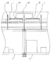
本実施例1の非接触浮上搬送機能を有する基板処理装置は、図1に示すように、基板1を装置に投入する基板ローダー5と、水又は薬液処理ユニット7と、リンス処理ユニット8と、乾燥処理ユニット9と、基板1を装置から取り出す基板アンローダー6とにより、概略構成されている。基板1は、基板ローダー5から基板アンローダー6に向かって、図1、図4、図5においては、図面の左から右に向かって、搬送されながら、各処理がなされていく。
以下に、本実施例1の主要部分である、水又は薬液処理ユニット7と、リンス処理ユニット8と、乾燥処理ユニット9と、それぞれの処理ユニットに共通の基板浮上ユニット10とについて、それぞれ詳細に説明する。なお、本実施例1では、基板の上下両面処理の場合を説明する。
Example 1
(Schematic configuration of the device)
Next, an embodiment (Embodiment 1) of the present invention will be described.
As shown in FIG. 1, the substrate processing apparatus having the non-contact levitation transfer function of the first embodiment includes a
Hereinafter, the water or
(基板浮上ユニット)
先ず、基板浮上ユニット10について説明する。基板浮上ユニット10は、基板1の下面に向かって水、薬液、空気、窒素ガスといった流体を噴出して、基板1を該流体で浮上させ、これにより、基板1の下面に非接触で該基板1の位置を保持するように機能するものであり、連続して装置の全長にわたって複数配置されている。なお、この場合、基板1の下面は、基板浮上ユニット10より噴出された流体を浴びて、所定の処理が行われる。
(Substrate floating unit)
First, the
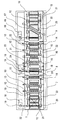
基板浮上ユニット10は、図2(a)に示すように、長い直方体形状のヘッダーのような構造をなしており、内部に水、薬液、空気、窒素ガスといった流体が充填される。そして、その上部の平面には、該流体を噴出させるための円形の孔11が複数形成されており、この孔11から噴出した流体の噴流が、図2(b)に示すように、基板1の下面に滑らかに当たって、しばらく層流状に広がり、やがて自然落下しつつ、基板1を浮上させる。
As shown in FIG. 2A, the
詳細には、この孔11から基板1の下面に向かって噴出した流体の噴流は、基板1に滑らかに衝突し、その後、基板1の下面に沿って全方位方向に一様に層流状に流れてから、自然落下しつつ、基板1を浮上させるものである。この場合において、この流体の流れは、隣接する孔11から同じように基板1の下面に向かって噴出して基板1に衝突し、その後、基板1の下面に沿って全方位方向に一様に層流状に流れる流体の流れと、基板1の下面上で衝突する場合もあるが、衝突するに至らない場合もある。衝突するまでの範囲を最大としてその範囲内で、各孔11から噴出した各流体の流れは、基板1の下面に沿って全方位方向に一様に層流状に流れてから、その後、自然落下する。
Specifically, the jet of fluid ejected from the
図2(c)に示す、基板浮上ユニット10の上部の平面に形成されたスリットA102は、前記した円形の孔11に代わるものである。このスリットA102は、基板浮上ユニット10の上部の平面の長さ方向略全長に及んでいるが、これに限られず、途中で数分割された形状に構成されても良い。
A slit A102 formed in the upper plane of the
図3(a)には、基板浮上ユニット10の更に他の例が示されている。この基板浮上ユニット10においては、その基板1に対向する上面が、基板進行方向中央部が基板進行方向に直交する方向に沿って窪むV字形状となっており、そのV字形状の窪みの底部に、水、薬液、空気、窒素ガスといった流体を噴出させる、基板1の幅の又は基板1の幅より長い1本のスリット状の孔(スリットB)103が設けられている。そして、このスリットB103から基板1の下面に向かって噴出した流体が、図3(b)に示すように、基板1の下面に滑らかに衝突して、反転して、該窪みを充満させ、該窪みを充満させた流体が該窪みから溢流しながら、基板1の下面に沿って全方位方向に一様に層流状に流れるようになっている。
FIG. 3A shows still another example of the
(水又は薬液処理ユニット、基板搬送ユニット)
次に、水又は薬液処理ユニット7の構成を、図4及び図5を参照しながら、詳細に説明する。
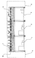
水又は薬液処理ユニット7の上部には、本実施例では、10個の基板浮上ユニット10が配置されており、該基板浮上ユニット10の図4、図5中、左から1番目から9番目までの基板浮上ユニット10からは、水又は薬液が噴出される。10番目の基板浮上ユニット10からは、空気が噴出される。左から6番目と8番目の基板浮上ユニット10の上部には、水又は薬液シャワーノズル13がそれぞれ配置されている。左から10番目の基板浮上ユニット10の上部には、基板1の上面に溜まった水又は薬液を空気流で吹き飛ばす、液切りエアーナイフ14が配置されている。該液切りエアーナイフ14とその下部の基板浮上ユニット10とは、それらの前後側が壁で仕切られた構成になっている。
(Water or chemical treatment unit, substrate transport unit)
Next, the configuration of the water or
In the present embodiment, ten
基板1の搬送方向から見て、その左右両側のエッジ部に水平方向から接触し、基板1を移動させる基板搬送ローラー(以下、搬送ローラーと略称する場合がある。)12は、本実施例の水又は薬液処理ユニット7では、5組配置されている。この内、図4、図5の左から2組は、基板1の投入時に、基板搬送ローラー12を保持している基板搬送ローラーアーム21が、基板1の進行方向に対して左右の水平方向に互いに遠ざかるように移動し、基板1がセットされる時、これらの基板搬送ローラー12が邪魔にならないように退避する構造となっている。なお、この基板搬送ローラー12を保持している基板搬送ローラーアーム21を移動させる機構は、装置内の全ての基板搬送ローラー12に備わっている。
A substrate transport roller 12 (hereinafter sometimes abbreviated as “transport roller”) 12 that moves the
また、この基板搬送ローラーアーム21を移動させる機構は、図7(b)に示すように、通常の幅サイズの基板1(図7(a)参照)より幅の狭い小基板101の処理の場合も、小基板101を挟んで対向する各対の基板搬送ローラー12、12の間隔を変えることにより対応できる構造となっている。この場合、基板搬送ローラー12は、基板1の搬送方向に平行な直線上の位置であって、隣接する2つの基板浮上ユニット10、10間の隙間がある位置にそれぞれ設けられているので、この隙間内に進入するように、同機構により移動させられることができる(図7(b)、図6参照)。
Further, as shown in FIG. 7B, the mechanism for moving the substrate
基板搬送ローラー12は、図5に示すように、基板搬送ローラー駆動モーター18からの回転力が、駆動シャフト22、ギアボックス19及び基板搬送ローラー駆動ギアボックス20を経由して伝えられることにより、回転する。これらは、基板搬送ユニットを構成している。
As shown in FIG. 5, the
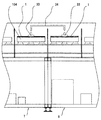
水又は薬液処理ユニット7の下部には、水又は薬液を入れる水又は薬液タンク25と、基板浮上ユニット10へ水又は薬液を圧送する、水又は薬液ポンプA27と、水又は薬液シャワーノズル13へ水又は薬液を圧送する、水又は薬液ポンプB28とが設置されている。
液切りエアーナイフ14と10番目の基板浮上ユニット10への空気の供給は、後述する、乾燥処理ユニット9の下部に配置されたエアーブロアー31により行われる。
In the lower part of the water or chemical
Air is supplied to the liquid cutting
(リンス処理ユニット)
次に、リンス処理ユニット8の構成を、図4、図5を参照しながら、詳細に説明する。
リンス処理ユニット8の上部には、本実施例1では、9個の基板浮上ユニット10が配置されている。これらの基板浮上ユニット10の内、図4、図5の左から1番目から8番目までの基板浮上ユニット10からは、水が噴出される。また、9番目の基板浮上ユニット10からは、空気が噴出される。本実施例1では、図の左から2番目の基板浮上ユニット10と3番目の基板浮上ユニット10との間には、上下1対の回転ブラシ(両面ブラシ洗浄手段)23が配置されており、これらの回転ブラシ23は、回転ブラシ駆動モーター24により回転させられる。また、これらの回転ブラシ23を濡らすように、図の左側から1本目と2本目の水シャワーノズル15が配置されている。
(Rinsing unit)
Next, the configuration of the
In the first embodiment, nine
さらに、本実施例1では、水をパルス状に噴出し、基板1の上面を洗浄する、水パルスガンノズル16が配置されている。また、水パルスの処理の後に、最終的にリンス処理を行う、図の左側から3本目の水シャワーノズル15が配置されている。そして、この水シャワーノズル15から噴出される水と、水シャワーノズル15に対向して配置された、図の右側から3番目の基板浮上ユニット10から噴出される水とには、図示しない超音波ユニットで発生した超音波振動をそれぞれ付加することができる構造になっている。
Further, in the first embodiment, a water
また、図4、図5の左から9番目の基板浮上ユニット10(このユニットからは、前記のとおり、空気が噴射される。)の上部には、基板1の上面に溜まった水を空気流で吹き飛ばす、液切りエアーナイフ14が配置されている。
Also, water accumulated on the upper surface of the
基板1の左右両側エッジ部に水平方向から接触し、基板1を移動させる、複数の基板搬送ローラー12は、本実施例1では、リンス処理ユニット8に、5組配置されている。 これらの基板搬送ローラー12は、基板搬送ローラー駆動モーター18からの回転力が、駆動シャフト22、ギアボックス19及び基板搬送ローラー駆動ギアボックス20を経由して伝えられることにより、回転する。
In the first embodiment, five sets of the plurality of
リンス処理ユニット8の下部には、水を入れる水タンク26と、基板浮上ユニット10へ水を圧送する水ポンプA29と、水シャワーノズル15へ水を圧送する水ポンプB30とが配置されている。
Below the rinse
(乾燥処理ユニット)
次に、乾燥処理ユニット9の構成を、図4、図5を参照しながら、詳細に説明する。
乾燥処理ユニット9の上部には、本実施例では、7個の基板浮上ユニット10が配置されており、これらの基板浮上ユニット10の内、図4、図5の左から2番目と3番目の基板浮上ユニット10は、基板1の上下面を乾燥させるための上下一対の乾燥エアーナイフ17を配置するため、変形した形状になっている。これら7個の基板浮上ユニット10と、乾燥エアーナイフ17からは、空気(圧縮空気)が噴出される。
なお、7個の基板浮上ユニット10から噴出される空気については、空気に代えて、窒素が使用されることもある。
(Dry processing unit)
Next, the configuration of the drying
In the present embodiment, seven
Note that nitrogen may be used in place of air for the air ejected from the seven
基板1の左右両側のエッジ部に水平方向から接触し、基板1を移動させる複数の基板搬送ローラー12は、本実施例1の乾燥処理ユニット9では、4組配置されている。この内、図4、図5の右から2組は、基板1の取り出し時に、基板搬送ローラー12を保持する基板搬送ローラーアーム21が、基板1の進行方向に対して左右の水平方向に互いに遠ざかるように移動して、基板1の搬送路を開く構造となっている。
In the drying
これらの基板搬送ローラー12は、基板搬送ローラー駆動モーター18からの回転力が、駆動シャフト22、ギアボックス19及び基板搬送ローラー駆動ギアボックス20を経由して伝えられることにより、回転する。
These
乾燥処理ユニット9の下部には、エアーブロアー31が配置されている。そして、このエアーブロアー31からは、空気が、乾燥処理ユニット9内にある、7個の基板浮上ユニット10と、乾燥エアーナイフ17と、リンス処理ユニット8内にある、液切りエアーナイフ14と、該液切りエアーナイフ14の下方に設けられた基板浮上ユニット10と、水又は薬液処理ユニット7内にある、液切りエアーナイフ14と、該液切りエアーナイフ14の下方に設けられた基板浮上ユニット10とに、それぞれ圧送される。
なお、乾燥処理ユニット9内にある、基板浮上ユニット10から噴出される空気に代えて窒素が使用される場合には、窒素の供給系統が別途設けられることになる。
An
In addition, when nitrogen is used instead of the air ejected from the
(作動の説明)
(基板の投入)
次に、このようにして構成される、本実施例1の非接触浮上搬送機能を有する基板処理装置の作動について説明する。
先ず、処理される基板1は、図1に示す基板ローダー5により、本実施例1の非接触浮上搬送機能を有する基板処理装置の、水又は薬液処理ユニット7に投入される。図示しない基板投入アームにより、基板1が、水又は薬液処理ユニット7内に降りて来ると、基板搬送ローラー12を保持している基板搬送ローラーアーム21が、基板1の進行方向に対して左右の水平方向から基板1に近づく方向に移動し、対向する2組の基板搬送ローラー12、12が、基板1の左右のエッジ部に水平方向から接触する。同時に、基板投入アームが退避し、水又は薬液処理ユニット7に配置された、10個の基板浮上ユニット10の内の、図4、図5の左から1番目から4番目までの基板浮上ユニット10からは、水又は薬液の噴出が開始される。本実施例1の場合、基板1の大きさは、これら4つの基板浮上ユニット10により丁度支持される大きさである。
(Description of operation)
(Substrate loading)
Next, the operation of the substrate processing apparatus having the non-contact levitation transfer function according to the first embodiment configured as described above will be described.
First, the
(洗浄)
次に、基板浮上ユニット10の内の、図4、図5の左から5番目から9番目までの基板浮上ユニット10及び2個の水又は薬液シャワーノズル13からも、水又は薬液の噴出が始まり、10番目の基板浮上ユニット10及び液切りエアーナイフ14からは空気の噴出が始まる。同時に、基板搬送ローラー12が回転を始め、基板1を所定のスピードで搬送開始する。
基板1の後端が、左から4番目の基板浮上ユニット10を通過すると、1番目から4番目までの基板浮上ユニット10からの水又は薬液の噴出は停止する。
(Washing)
Next, the ejection of water or chemical starts from the
When the rear end of the
(液切り)
基板1は、図4、図5の左から1番目から9番目までの基板浮上ユニット10及び水又は薬液シャワーノズル13からの水又は薬液の噴出で洗浄され、同10番目の基板浮上ユニット10及び液切りエアーナイフ14からの空気の噴出で、基板1上下面に溜まっていた、水又は薬液が吹き飛ばされて、次のリンス処理ユニット8へ搬送される。
基板1の後端が、該液切りエアーナイフ14の下を通過すると、水又は薬液処理ユニット7での水又は薬液の噴出や空気の噴出は停止され、基板搬送ローラー12の回転も停止される。
(Liquid draining)
The
When the rear end of the
(リンス処理)
基板1の先端がリンス処理ユニット8に入ってくると、該リンス処理ユニット8内の基板搬送ローラー12が回転を始め、同時に、該リンス処理ユニット8内の9個の基板浮上ユニット10の内の、図4、図5の左から1番目から4番目までの基板浮上ユニット10からの水の噴出及び左から1番目と2番目の水シャワーノズル15からの水の噴出が始まり、回転ブラシ23が回転を開始する。基板1の先端が、4番目の基板浮上ユニット10を通過すると、9個の基板浮上ユニット10の内の、図4、図5の左から5番目から8番目までの基板浮上ユニット10、及び、水パルスガンノズル16と左から3番目の水シャワーノズル15からも、水の噴出が始まり、同時に、図示しない超音波ユニットが作動し、該図の左側から3本目の水シャワーノズル15から噴出する水と、これに対向する、図の右側から3番目の基板浮上ユニット10から噴出する水とに、超音波振動が付加される。
図の左側から9番目の基板浮上ユニット10及び液切りエアーナイフ14からは、空気の噴出が始まる。
(Rinse treatment)
When the front end of the
From the ninth
リンス処理ユニット8において、基板1の後端が左から4番目の基板浮上ユニット10を通過すると、1番目から4番目までの基板浮上ユニット10からの水の噴出、左から1番目と2番目の水シャワーノズル15からの水の噴出、回転ブラシ23の回転が停止する。
In the
基板1は、回転ブラシ23と水パルスガンノズル16からの圧力水で洗浄され、左から3番目の水シャワーノズル15でリンスされ、9番目の基板浮上ユニット10及び液切りエアーナイフ14からの空気の噴出で、基板1上下面に溜まっていた水が吹き飛ばされて、次の乾燥処理ユニット9へ搬送される。
基板1の後端が、液切りエアーナイフ14の下を通過すると、リンス処理ユニット8における水の噴出や空気の噴出及び超音波ユニットの作動は停止され、基板搬送ローラー12の回転も停止する。
The
When the rear end of the
(乾燥工程)
基板1の先端が乾燥処理ユニット9に入ってくると、該乾燥処理ユニット9内の基板搬送ローラー12が回転を始め、同時に、該乾燥処理ユニット9内の7個の基板浮上ユニット10及び上下一対の乾燥エアーナイフ17からの空気の噴出が始まる。基板1は、上下一対の乾燥エアーナイフ17の間を通過する間に、基板1の上下面共、乾燥される。
(Drying process)
When the front end of the
(基板の取り出し)
基板1の先端が乾燥処理ユニット9の右端に達すると、基板搬送ローラー12が回転を停止する。同時に、図4、図5の左から1番目から3番目までの基板浮上ユニット10からの空気の噴出と乾燥エアーナイフ17からの空気の噴出を停止する。
(Removal of substrate)
When the front end of the
次いで、図1で示した基板アンローダー6から、図示しない基板取り出しアームが降りて来て、基板1のエッジ部を掴むと、左から4番目から7番目までの基板浮上ユニット10からの空気の噴出を停止する。同時に、乾燥処理ユニット9に4組配置されている基板搬送ローラー12の内の、図4、図5の右から2組の基板搬送ローラー12が、該基板搬送ローラー12を保持している基板搬送ローラーアーム21が基板1の進行方向に対して左右の水平方向に互いに遠ざかる方向に移動することにより開き、基板アンローダー6の、図示しない基板取り出しアームによって、基板1が該乾燥処理ユニット9から取り出されて、処理を終了する。
Next, when a substrate unloading arm (not shown) descends from the
(実施例1の効果)
本実施例1の非接触浮上搬送機能を有する基板洗浄処理装置は、前記のように構成されていて、前記のように作動するので、次のような効果を奏することができる。
水による洗浄処理、薬液による化学的処理(洗浄、現像、エッチング、剥離等)をされる基板1は、最初の水洗浄又は化学的処理工程から最後の乾燥処理工程までの全ての処理工程において、基板浮上ユニット10により、液体又は空気といった流体で浮上させられた状態で処理されるので、基板1の上面も下面も接触による汚染を防ぐことができる。
(Effect of Example 1)
Since the substrate cleaning apparatus having the non-contact levitation transfer function of the first embodiment is configured as described above and operates as described above, the following effects can be obtained.
The
また、基板1のエッジ部に水平方向から接触して回転する基板搬送ローラー12による機械的な力により、基板を高速かつ安定的に移動させることができる。さらに、基板搬送ローラー12は、水平方向から基板1のエッジ部のみに接触するという構造のため、基板1の上面も下面も接触による汚染を防ぐことができ、また、ローラー痕の生成を防ぐことができる。
Further, the substrate can be moved at high speed and stably by the mechanical force of the
また、装置の全長にわたり複数配置された基板浮上ユニット10の各々に、選択的に、薬液、水、空気、窒素ガスといった流体を精密に制御しながら供給停止させることができるので、常時、全基板浮上ユニット10に流体を流さず、基板が通過する部分の基板浮上ユニット10のみへ、必要な量の流体を順次供給して行けるので、流体の消費量を低く抑えることができるとともに、薬液や水といった液体を圧送するポンプの容量を小さいもので済ますことができる。
Further, since it is possible to selectively stop supply of fluids such as a chemical solution, water, air, and nitrogen gas to each of the plurality of
さらに、基板1を浮上させる流体が、基板浮上ユニット10の上部平面(液噴出面)に設けられた流体噴出孔(円形又はスリット状の孔)11、102から基板1の下面に向かって均一に噴出するようにされるので、基板1は、該流体によって面状の均一な強い押し上げ力を受ける。このため、基板1の両面処理の場合、基板上部より噴射される水又は薬液のシャワーによる、基板上部から加えられる打力(圧力)を受けても、基板1を浮上させた状態を保持できる。さらに、基板1を押し上げる力が、面状で均一なため、厚みの薄い基板も処理することができる。
加えて、水による洗浄処理、薬液による化学的処理の場合、基板浮上ユニット10からも水又は薬液が噴出するが、この時、基板下面に衝突した水又は薬液は、層流状の層をなして、基板1の下面に沿って全方位方向に一様に流れるため、基板1の下面もムラの無い均一な洗浄又はエッチング等の化学的処理ができる。
Further, the fluid that floats the
In addition, in the case of cleaning treatment with water and chemical treatment with chemical solution, water or chemical solution is also ejected from the
また、基板1を浮上させる流体が、基板浮上ユニット10の上面のV字形状の窪みの底部に設けられた流体噴出孔(長い1本のスリット状の孔)103から基板1の下面に向かって均一に噴出するようにされる場合には、この流体は、V字形状の窪みを充満させ、そこから溢流しながら、基板の下面に沿って全方位方向に一様に流れるため、基板1は、該流体によって面状の均一な強い押し上げ力を受ける。このため、基板1の両面処理の場合、基板上部より噴射される水又は薬液のシャワーによる、基板上部から加えられる打力(圧力)を受けても、基板1を浮上させた状態を保持できる。さらに、基板1を押し上げる力が、面状で均一なため、厚みの薄い基板も処理することができる。
加えて、水による洗浄処理、薬液による化学的処理の場合、該基板浮上ユニット10からも水又は薬液が噴出するが、この時、V字形状の窪みに充満した水又は薬液は、そこから溢流しながら、層流状の層をなして、基板1の下面に沿って全方位方向に一様に流れるため、基板1の下面も、より一層ムラのない均一な洗浄又はエッチング等の化学的処理ができる。
Further, the fluid that floats the
In addition, in the case of cleaning treatment with water and chemical treatment with chemical solution, water or chemical solution is also ejected from the
また、リンス処理ユニット8において、図の左側から3本目の水シャワーノズル15から噴出する水と、これに対向する、図の右側から3番目の基板浮上ユニット10から噴出する水に、超音波振動が付加されるので、水又は薬液によるリンス効果に加え、超音波振動による機械的な力が付加されて、より一層リンス効果を高めることができる。
Further, in the
さらに、少なくとも1個所、隣り合う2つの基板浮上ユニット10、10間に、両面ブラシ洗浄手段23が備えられているので、ブラシの機械的な力で、基板上下面の汚染物質を払い落すことができ、基板両面洗浄において、基板上下面の洗浄効果を更に向上させることができる。
Furthermore, since the double-sided brush cleaning means 23 is provided between two adjacent
また、少なくとも1つ、水をパルス状に噴出し、基板の上面を洗浄するパルスガン16が備えられているので、パルスガン16による水流が、パルス状に噴射される水の高い流速と圧力により、基板上面の汚染物質を吹き飛ばすことができ、基板片面洗浄において、基板上面の洗浄効果を更に向上させることができる。
In addition, since at least one
さらに、また、複数の搬送ローラー12は、基板1の搬送方向に平行な直線上の位置であって、隣接する2つの基板浮上ユニット10、10間の隙間がある位置にそれぞれ設けられ、処理する基板1の幅サイズに合わせて、基板を挟んで対向する各対の搬送ローラー12、12間の間隔を可変にする手段が備えられているので、処理される基板1の幅サイズが基板浮上ユニット10の幅サイズを越えて変化しても、装置の部品や構成を変えることなく、複数の搬送ローラー12により、基板1を搬送することができる。
Further, the plurality of
(実施例2)
次に、本願の発明の他の実施例(実施例2)について説明する。
本実施例2の非接触浮上搬送機能を有する基板処理装置では、基板1の下面のみの処理が実行される。基板1は、薬液処理工程では、基板浮上ユニット10から噴出される薬液によって、基板1の下面のみの薬液処理が行われ、また、リンス処理工程では、基板浮上ユニット10から噴出される水によって、基板1の下面のみのリンス処理が行われる。
(Example 2)
Next, another embodiment (embodiment 2) of the present invention will be described.
In the substrate processing apparatus having the non-contact levitation transfer function according to the second embodiment, only the lower surface of the
この時、基板浮上ユニット10から噴出した水もしくは薬液が、基板1の上面に回り込まないように、図6に示されるように、複数の液回り込み防止エアーノズル32が、基板浮上ユニット10の上部に、基板1の進行方向に向かって傾斜するようにして、装置全体にわたって設けられており、この液回り込み防止エアーノズル32から高速の空気流が基板1の上面に吹き付けられ(矢印S1参照)、基板1の進行方向前面及び両側面からの水又は薬液が基板1の上面に回り込むのを防ぐ構成となっている。これにより、基板1の上面には、水又は薬液が一切触れることなく、基板1の下面を処理することができる。
At this time, as shown in FIG. 6, a plurality of liquid spill-preventing
しかも、この場合、液回り込み防止エアーノズル32は、その噴出口から噴出された空気が、隣接する2つの基板浮上ユニット10、10間の隙間を抜けて下方に放出される(矢印S2参照)位置に設けられているので、液回り込み防止エアーノズル32の噴出口から噴出された空気流が、基板1の後方で噴き上がる水又は薬液を基板1の後部上面に吹き上げることがなくなり、基板1の後方や側面からの水又は薬液の基板後部上面への回り込みも防ぐことができる。
In addition, in this case, the liquid squeezing
本実施例2の非接触浮上搬送機能を有する基板処理装置は、以上の点で実施例1の非接触浮上搬送機能を有する基板処理装置と異なっているが、その他の点で異なるところはなく、また、その作動も、基板1の移動経路の上部に配置された、水又は薬液シャワーノズル13、液切りエアーナイフ14、水シャワーノズル15、水パルスガンノズル16が作動せず、回転ブラシ23が基板1に接触しない位置に退避するところが異なるほかは、実施例1の非接触浮上搬送機能を有する基板処理装置と異なるところはないので、これ以上の詳細な説明を省略する。
The substrate processing apparatus having the non-contact levitation transfer function of the second embodiment is different from the substrate processing apparatus having the non-contact levitation transfer function of the first embodiment in the above points, but there is no difference in other points. In addition, the water or chemical
(実施例2の効果)
本実施例2の非接触浮上搬送機能を有する基板処理装置は、前記のように構成されていて、前記のように作動するので、次のような効果を奏することができる。
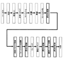
図9は、例として、従来のタッチパネルの回路パターンを形成するプロセスのフローを示している。回路を形成する材料の薄膜が形成された基板1の一方の面(回路形成面)に、エッチングにより回路を形成するプロセスで、先ず、基板1の回路形成面を洗浄工程、UV照射工程で清浄にし、レジストを塗布し、プリベーク工程でレジストを加熱して硬化させ、露光工程で紫外線により回路のパターンを焼き付け、次の現像工程で回路以外の部分のレジストを溶かし去り、ポストベーク工程でもう一度レジストを加熱し、レジストを硬化させる。
(Effect of Example 2)
Since the substrate processing apparatus having the non-contact levitation transfer function according to the second embodiment is configured as described above and operates as described above, the following effects can be obtained.
FIG. 9 shows a flow of a process for forming a circuit pattern of a conventional touch panel as an example. In the process of forming a circuit by etching on one surface (circuit formation surface) of the
次に、基板1のもう一方の面(回路形成面の裏側)に、以後のエッチング工程での薬品が接触しないように、レジストで保護膜を形成する。このための工程が、基板反転(基板をひっくり返す)、裏面レジスト塗布、裏面ポストベーク、基板反転の各工程である。
この後に、基板1の回路形成を行うため、エッチング工程で、前記レジストで保護された回路パターン以外の部分の回路形成材料を溶かし去り、次のレジスト剥離工程で、回路パターンの上に残ったレジストを溶かし去る。
この後、また基板を反転し、裏面レジスト剥離工程で、回路形成面の裏側に形成した保護膜のレジストを溶かし去り、基板1を反転して、基板1の回路形成面を上面に戻して、処理を終了する。
Next, a protective film is formed with a resist so that chemicals in the subsequent etching process do not come into contact with the other surface of the substrate 1 (the back side of the circuit formation surface). The steps for this are the substrate reversal (turning the substrate upside down), backside resist coating, backside post bake, and substrate reversal.
Thereafter, in order to perform circuit formation of the
After this, the substrate is turned over again, and the resist of the protective film formed on the back side of the circuit formation surface is melted away in the backside resist stripping step, the
これに対して、本実施例2の非接触浮上搬送機能を有する基板処理装置で、基板1の下面のみの処理を行って、タッチパネルの回路パターンを形成するプロセスのフローは、図10に示すとおりとなる。以下に、このプロセスフローを説明する。
In contrast, in the substrate processing apparatus having the non-contact levitation conveyance function of the second embodiment, the process flow for forming only the lower surface of the
基板1の回路形成面に回路パターンを焼き付ける露光工程までは、従来のプロセスと同じであるが、本実施例2の基板処理装置では、基板1の上面に一切の水及び薬液を接触させることなく処理できるので、従来のプロセスにある、回路形成面の裏側にレジストによる保護膜を形成し、またこれを剥離する必要がない。したがって、図9における最初の基板反転、裏面レジスト塗布、裏面ポストベーク、裏面レジスト剥離の各工程が不要となり、図10に示すように、露光工程後に基板1を反転し(ひっくり返し)、現像工程、ポストベーク工程、エッチング工程、レジスト剥離工程を行い、基板1を反転して回路形成面を上面に戻して、処理を終了する。
このように、本実施例2の非接触浮上搬送機能を有する基板処理装置では、回路形成工程の大幅な短縮が可能になる。
The process up to the exposure process in which the circuit pattern is printed on the circuit forming surface of the
As described above, in the substrate processing apparatus having the non-contact levitation conveyance function according to the second embodiment, the circuit forming process can be greatly shortened.
(実施例3)
次に、本願の発明の更に他の実施例(実施例3)について説明する。
実施例1及び2の非接触浮上搬送機能を有する基板処理装置では、基板1は、水又は薬液洗浄処理ユニット7とリンス処理ユニット8間を、基板浮上ユニット10で浮上させられながら、基板搬送ローラー12で連続的に搬送される構成となっていたが、本実施例3の基板処理装置では、図8に示すように、各処理ユニット間を壁で分離し、隣接する処理ユニット間の基板1の搬送を、ベルヌーイの原理を応用した非接触基板吸着ユニット33で行う構成となっており、基板1の搬送を、基板搬送ローラー12で行っていない。このような、ベルヌーイの原理を応用した非接触基板吸着ユニット33は、市販されている。
(Example 3)
Next, still another embodiment (embodiment 3) of the present invention will be described.
In the substrate processing apparatus having the non-contact levitating conveyance function of the first and second embodiments, the
さらに、基板浮上ユニット10も、実施例1及び2の非接触浮上搬送機能を有する基板処理装置と異なり、乾燥処理ユニット9以外は、基板1の面積(平面積)と同等又はそれより広い面積を有する、基板浮上ユニット104を備えており、基板1は、各処理ユニット内では移動せず、基板浮上ユニット104の上部に停止した状態で保持され、薬液やリンス等の各処理がなされ、処理が終わると、基板1は、非接触基板吸着ユニット33により持ち上げられ、隣接する次の処理ユニットへと搬送される。
Furthermore, unlike the substrate processing apparatus having the non-contact levitation conveyance function of the first and second embodiments, the
なお、基板浮上ユニット10、104の幅(基板1の搬送方向と直交する方向の長さ)は、基板1の幅と略同等であるので、基板浮上ユニット104が、基板1の面積と同等又はそれより広い面積を有しているということは、基板浮上ユニット104が、基板1の搬送方向長さと同等又はそれより大きい長さを有しているということと同義である。
本実施例3で使用される基板浮上ユニット104は、基板1の搬送方向長さと同等又はそれより大きい長さを有しており、実施例1及び2の基板処理装置で使用された、基板1の搬送方向長さより小さい長さを有する基板浮上ユニット10を短冊型基板浮上ユニットとすれば、長冊型基板浮上ユニットに属するものである。
Note that the width of the
The
本実施例3の非接触浮上搬送機能を有する基板処理装置は、以上の点で実施例1及び2の非接触浮上搬送機能を有する基板処理装置と異なっているが、その他の点で異なるところはなく、また、その作動も、乾燥処理ユニット9以外の各処理ユニット間の、基板1の搬送形態が異なっていることと、基板1が乾燥処理ユニット9以外の処理ユニット内で基板1の面積と同等又はそれより広い面積を有する基板浮上ユニット104上に停止した状態で各処理がなされることの他は、実施例1及び2の非接触浮上搬送機能を有する基板処理装置と異なるところはないので、これ以上の詳細な説明を省略する。
The substrate processing apparatus having the non-contact levitation transfer function of the third embodiment is different from the substrate processing apparatus having the non-contact levitation transfer function of the first and second embodiments in the above points, but is different in other points. Also, the operation of the
(実施例3の効果)
本実施例3の非接触浮上搬送機能を有する基板処理装置は、前記のように構成されていて、前記のように作動するので、次のような効果を奏することができる。
実施例1及び2のように、基板1が各処理ユニット間を連続的に搬送される場合、例えば、基板1が水又は薬液処理ユニット7からリンス処理ユニット8へ連続的に搬送される場合、特に水又は薬液処理ユニット7で薬液が使用されていると、基板1が両方の処理ユニットに跨って搬送される時には、リンス処理ユニット8から水が、水又は薬液処理ユニット7に流れ込んで、薬液の濃度を変化させることがあるが、非接触基板吸着ユニット33で基板1を持ち上げて搬送(図8、搬送経路34参照)することにより、水又は薬液処理ユニット7の処理槽とリンス処理ユニット8の処理槽を完全に分離でき、前記のような薬液の濃度変化を防ぐことができる。
(Effect of Example 3)
Since the substrate processing apparatus having the non-contact levitation transfer function according to the third embodiment is configured as described above and operates as described above, the following effects can be obtained.
When the
また、連続搬送方式の場合、薬液と水の混入を防ぐため、水又は薬液処理ユニット7とリンス処理ユニット8との間には、液切りエアーナイフ14が備えられるが、例えば、剥離工程などで使用される薬品などは、該液切りエアーナイフ14で中途半端に乾燥すると、後のリンス工程で、水でリンスされにくいという問題が生じる場合があるが、非接触基板吸着ユニット33で持ち上げて搬送すれば、基板下面の薬品は乾燥されずにリンス処理されるため、リンス処理を容易にすることができる。
In the case of the continuous conveyance system, a liquid draining
加えて、処理しようとする基板1を、基板1の搬送方向長さと同等又はそれより大きい長さを有する基板浮上ユニット(換言すれば、基板1の面積と同等又はそれより広い面積を有する基板浮上ユニット)104の上方に、水又は薬液の噴流で浮上させながら停止させた状態で保持できるので、例えば、レジスト剥離工程のように薬液処理時間が長い場合の処理でも、連続搬送処理と異なり、処理ユニットの長さを長くする必要がなく、処理装置をコンパクトにすることができる。
In addition, the
本願の発明は、以上の実施例に限定されず、その要旨を逸脱しない範囲において、種々の変形が可能である。
例えば、実施例2の基板処理装置において、基板搬送ローラー12に代えて、実施例3で述べた、ベルヌーイの原理を応用した非接触基板吸着ユニット33を使用しても良く、これにて基板1を、各処理ユニット内で又は隣接する2つの処理ユニット間で、搬送するようにすれば、基板1の上面への水又は薬液の回り込みがなくなるので、液回り込み防止エアーノズル32を不要にすることができる。
The invention of the present application is not limited to the above embodiments, and various modifications can be made without departing from the scope of the invention.
For example, in the substrate processing apparatus according to the second embodiment, the non-contact substrate suction unit 33 to which the Bernoulli principle described in the third embodiment is applied may be used instead of the
また、図示しない超音波ユニットで発生した超音波振動は、本実施例1では、リンス処理ユニット8内に配置された、図の左側から3本目の水シャワーノズル15から噴出される水と、該水シャワーノズル15に対向して配置された、図の右側から3番目の基板浮上ユニット10から噴出される水とにのみ付加されたが、これに限定されず、その他の水シャワーノズルや基板浮上ユニット10から噴出される水にも、適宜、付加されて良い。
In the first embodiment, the ultrasonic vibration generated by the ultrasonic unit (not shown) is disposed in the
1…基板、2…底部搬送ローラー、3…水流ボックス、4…水流、5…基板ローダー、6…基板アンローダー、7…水又は薬液洗浄処理ユニット、8…リンス処理ユニット、9…乾燥処理ユニット、10…基板浮上ユニット、11…流体噴出口、12…基板搬送ローラー、13…水又は薬液シャワーノズル、14…液切りエアーナイフ、15…水シャワーノズル、16…水パルスガンノズル、17…乾燥エアーナイフ、18…基板搬送ローラー駆動モーター、19…ギアボックス、20…基板搬送ローラー駆動ギアボックス、21…基板搬送ローラーアーム、22…駆動シャフト、23…回転ブラシ(両面ブラシ洗浄手段)、24…回転ブラシ駆動モーター、25…水又は薬液タンク、26…水タンク、27…水又は薬液ポンプA、28…水又は薬液ポンプB、29…水ポンプA、30…水ポンプB、31…エアーブロアー、32…液回り込み防止エアーノズル、33…非接触基板吸着ユニット、34…基板移動経路、101…小基板、102…流体噴出スリットA、103…流体噴出スリットB、104…基板浮上ユニット。
DESCRIPTION OF
Claims (14)
前記基板の下面に向かって水、薬液、空気、窒素ガスといった流体を噴出し、前記基板を前記流体で浮上させて、前記基板の下面に非接触で前記基板の位置を保持する、連続して装置の全長にわたり複数配置された基板浮上ユニットと、
前記基板の搬送方向から見て前記基板の左右両側のエッジ部に水平方向から接触して、前記基板を移動させる複数配置された搬送ローラーを有する基板搬送ユニットと、
を備えたことを特徴とする非接触浮上搬送機能を有する基板処理装置。 The substrate is floated without contacting anything other than fluids such as water, chemicals, air, and nitrogen gas on the lower surface of the substrate, and the substrate is moved, while the upper surface and the lower surface of the substrate or only the lower surface are washed with water. Multiple substrates such as water or chemical treatment units, rinse treatment units, and dry treatment units that perform chemical treatment with chemical solutions, rinse treatment with water, or dry treatment with a gas such as air or nitrogen gas sprayed from above and below the substrate. A substrate processing apparatus having a non-contact levitation conveyance function comprising a processing unit,
A fluid such as water, chemical solution, air, or nitrogen gas is ejected toward the lower surface of the substrate, the substrate is floated by the fluid, and the position of the substrate is maintained in a non-contact manner on the lower surface of the substrate. A plurality of substrate levitation units arranged over the entire length of the apparatus;
A substrate transport unit having a plurality of transport rollers arranged to contact the edge portions on the left and right sides of the substrate from the horizontal direction when viewed from the transport direction of the substrate and move the substrate,
A substrate processing apparatus having a non-contact levitating conveyance function.
前記非接触吸着ユニットは、前記複数の基板処理ユニットのうちの隣接する2つの基板処理ユニット間で前記基板を持ち上げて、次の基板処理ユニットへ前記基板を搬送する
ことを特徴とする請求項12に記載の非接触浮上搬送機能を有する基板処理装置。 The substrate floating unit has a length equal to or greater than the length of the substrate in the conveyance direction,
13. The non-contact suction unit lifts the substrate between two adjacent substrate processing units among the plurality of substrate processing units, and conveys the substrate to the next substrate processing unit. A substrate processing apparatus having a non-contact levitation transfer function described in 1.
処理する前記基板の幅サイズに合わせて、前記基板を挟んで対向する各対の前記搬送ローラー間の間隔を可変にする手段を更に備えた
ことを特徴とする請求項1に記載の非接触浮上搬送機能を有する基板処理装置。
The plurality of transport rollers are provided at positions on a straight line parallel to the transport direction of the substrate, and at a position where there is a gap between two adjacent substrate floating units,
2. The non-contact levitation according to claim 1, further comprising means for varying a distance between each pair of the transport rollers facing each other across the substrate in accordance with a width size of the substrate to be processed. A substrate processing apparatus having a transfer function.
Priority Applications (3)
| Application Number | Priority Date | Filing Date | Title |
|---|---|---|---|
| JP2011048647A JP5877954B2 (en) | 2011-03-07 | 2011-03-07 | Substrate processing apparatus having non-contact levitation transfer function |
| TW100145876A TWI457266B (en) | 2011-03-07 | 2011-12-13 | And a substrate processing device having a non-contact floating conveyance function |
| KR1020120013634A KR101335885B1 (en) | 2011-03-07 | 2012-02-10 | Substrate processing apparatus with a non-contact floating transfer system |
Applications Claiming Priority (1)
| Application Number | Priority Date | Filing Date | Title |
|---|---|---|---|
| JP2011048647A JP5877954B2 (en) | 2011-03-07 | 2011-03-07 | Substrate processing apparatus having non-contact levitation transfer function |
Publications (2)
| Publication Number | Publication Date |
|---|---|
| JP2012186325A true JP2012186325A (en) | 2012-09-27 |
| JP5877954B2 JP5877954B2 (en) | 2016-03-08 |
Family
ID=47016118
Family Applications (1)
| Application Number | Title | Priority Date | Filing Date |
|---|---|---|---|
| JP2011048647A Expired - Fee Related JP5877954B2 (en) | 2011-03-07 | 2011-03-07 | Substrate processing apparatus having non-contact levitation transfer function |
Country Status (3)
| Country | Link |
|---|---|
| JP (1) | JP5877954B2 (en) |
| KR (1) | KR101335885B1 (en) |
| TW (1) | TWI457266B (en) |
Cited By (6)
| Publication number | Priority date | Publication date | Assignee | Title |
|---|---|---|---|---|
| CN103915365A (en) * | 2012-12-28 | 2014-07-09 | 芝浦机械电子装置股份有限公司 | Bonding apparatus and bonding process method |
| JP2015043385A (en) * | 2013-08-26 | 2015-03-05 | 株式会社ダン科学 | Substrate processing device having edge conveyance function |
| JP2016539880A (en) * | 2013-11-04 | 2016-12-22 | コーニング精密素材株式会社Corning Precision Materials Co., Ltd. | Non-contact vibration suppressing device and object processing method |
| CN107459263A (en) * | 2016-06-02 | 2017-12-12 | 盟立自动化股份有限公司 | Wet processing equipment |
| CN107572832A (en) * | 2016-07-04 | 2018-01-12 | 盟立自动化股份有限公司 | Wet processing equipment |
| JP2020047820A (en) * | 2018-09-20 | 2020-03-26 | 株式会社Nsc | Float transportation device |
Families Citing this family (3)
| Publication number | Priority date | Publication date | Assignee | Title |
|---|---|---|---|---|
| TWI570806B (en) * | 2013-11-11 | 2017-02-11 | 東京威力科創股份有限公司 | System and method for enhanced removal of metal hardmask using ultra violet treatment |
| CN110670070A (en) * | 2019-11-19 | 2020-01-10 | 江苏上达电子有限公司 | Design method of liquid floating spraying disc |
| KR102359377B1 (en) * | 2020-03-18 | 2022-02-08 | 주식회사 세정로봇 | wet wafer mounting device |
Citations (13)
| Publication number | Priority date | Publication date | Assignee | Title |
|---|---|---|---|---|
| JPH0329919A (en) * | 1989-06-27 | 1991-02-07 | Sharp Corp | Method for washing glass substrate of liquid crystal display element |
| JPH09246224A (en) * | 1996-03-07 | 1997-09-19 | Sony Corp | Cleaning method for wafer |
| JPH10154652A (en) * | 1996-11-26 | 1998-06-09 | Dainippon Screen Mfg Co Ltd | Substrate treating device |
| JP2002053983A (en) * | 2000-08-03 | 2002-02-19 | Shiizu:Kk | Substrate treatment apparatus |
| US20030169524A1 (en) * | 2001-12-27 | 2003-09-11 | Orbotech Ltd | System and methods for imaging employing a levitating conveyor |
| JP2004342886A (en) * | 2003-05-16 | 2004-12-02 | Sharp Corp | Equipment and method of processing substrate |
| JP2006176255A (en) * | 2004-12-21 | 2006-07-06 | Murata Mach Ltd | Conveying system |
| JP2006206324A (en) * | 2005-01-26 | 2006-08-10 | Sfa Engineering Corp | Substrate carrying device |
| JP2006276348A (en) * | 2005-03-29 | 2006-10-12 | Sharp Corp | Substrate cleaning apparatus |
| JP2007182305A (en) * | 2006-01-06 | 2007-07-19 | Tokyo Electron Ltd | Board carrying device and its method, and computer program |
| JP2008140987A (en) * | 2006-12-01 | 2008-06-19 | Airtech Japan Ltd | Semiconductor wafer and apparatus for air floating and transporting liquid crystal glass |
| JP2008166359A (en) * | 2006-12-27 | 2008-07-17 | Tokyo Electron Ltd | Substrate processing apparatus |
| JP2009061388A (en) * | 2007-09-06 | 2009-03-26 | Zebiosu:Kk | High-pressure high-speed control jet gun |
Family Cites Families (4)
| Publication number | Priority date | Publication date | Assignee | Title |
|---|---|---|---|---|
| KR101024644B1 (en) * | 2004-01-30 | 2011-03-25 | 엘지디스플레이 주식회사 | An apparatus for conveying the glass substrate using fluid |
| JP2007175653A (en) * | 2005-12-28 | 2007-07-12 | Sharp Corp | Washing device, and manufacturing method of display device using the same |
| KR100922521B1 (en) * | 2007-10-11 | 2009-10-20 | 세메스 주식회사 | Brush assembly and apparatus for cleaning a substrate having the same |
| US8231157B2 (en) * | 2008-08-28 | 2012-07-31 | Corning Incorporated | Non-contact manipulating devices and methods |
-
2011
- 2011-03-07 JP JP2011048647A patent/JP5877954B2/en not_active Expired - Fee Related
- 2011-12-13 TW TW100145876A patent/TWI457266B/en not_active IP Right Cessation
-
2012
- 2012-02-10 KR KR1020120013634A patent/KR101335885B1/en not_active IP Right Cessation
Patent Citations (14)
| Publication number | Priority date | Publication date | Assignee | Title |
|---|---|---|---|---|
| JPH0329919A (en) * | 1989-06-27 | 1991-02-07 | Sharp Corp | Method for washing glass substrate of liquid crystal display element |
| JPH09246224A (en) * | 1996-03-07 | 1997-09-19 | Sony Corp | Cleaning method for wafer |
| JPH10154652A (en) * | 1996-11-26 | 1998-06-09 | Dainippon Screen Mfg Co Ltd | Substrate treating device |
| JP2002053983A (en) * | 2000-08-03 | 2002-02-19 | Shiizu:Kk | Substrate treatment apparatus |
| JP2005528586A (en) * | 2001-12-27 | 2005-09-22 | オーボテック リミテッド | Floating article transfer system and transfer method |
| US20030169524A1 (en) * | 2001-12-27 | 2003-09-11 | Orbotech Ltd | System and methods for imaging employing a levitating conveyor |
| JP2004342886A (en) * | 2003-05-16 | 2004-12-02 | Sharp Corp | Equipment and method of processing substrate |
| JP2006176255A (en) * | 2004-12-21 | 2006-07-06 | Murata Mach Ltd | Conveying system |
| JP2006206324A (en) * | 2005-01-26 | 2006-08-10 | Sfa Engineering Corp | Substrate carrying device |
| JP2006276348A (en) * | 2005-03-29 | 2006-10-12 | Sharp Corp | Substrate cleaning apparatus |
| JP2007182305A (en) * | 2006-01-06 | 2007-07-19 | Tokyo Electron Ltd | Board carrying device and its method, and computer program |
| JP2008140987A (en) * | 2006-12-01 | 2008-06-19 | Airtech Japan Ltd | Semiconductor wafer and apparatus for air floating and transporting liquid crystal glass |
| JP2008166359A (en) * | 2006-12-27 | 2008-07-17 | Tokyo Electron Ltd | Substrate processing apparatus |
| JP2009061388A (en) * | 2007-09-06 | 2009-03-26 | Zebiosu:Kk | High-pressure high-speed control jet gun |
Cited By (8)
| Publication number | Priority date | Publication date | Assignee | Title |
|---|---|---|---|---|
| CN103915365A (en) * | 2012-12-28 | 2014-07-09 | 芝浦机械电子装置股份有限公司 | Bonding apparatus and bonding process method |
| JP2015043385A (en) * | 2013-08-26 | 2015-03-05 | 株式会社ダン科学 | Substrate processing device having edge conveyance function |
| JP2016539880A (en) * | 2013-11-04 | 2016-12-22 | コーニング精密素材株式会社Corning Precision Materials Co., Ltd. | Non-contact vibration suppressing device and object processing method |
| CN107459263A (en) * | 2016-06-02 | 2017-12-12 | 盟立自动化股份有限公司 | Wet processing equipment |
| CN107572832A (en) * | 2016-07-04 | 2018-01-12 | 盟立自动化股份有限公司 | Wet processing equipment |
| JP2020047820A (en) * | 2018-09-20 | 2020-03-26 | 株式会社Nsc | Float transportation device |
| WO2020059796A1 (en) * | 2018-09-20 | 2020-03-26 | 株式会社Nsc | Flotation conveyance device |
| CN113412535A (en) * | 2018-09-20 | 2021-09-17 | 株式会社Nsc | Suspension conveying device |
Also Published As
| Publication number | Publication date |
|---|---|
| KR101335885B1 (en) | 2013-12-02 |
| JP5877954B2 (en) | 2016-03-08 |
| KR20120101990A (en) | 2012-09-17 |
| TW201236956A (en) | 2012-09-16 |
| TWI457266B (en) | 2014-10-21 |
Similar Documents
| Publication | Publication Date | Title |
|---|---|---|
| JP5877954B2 (en) | Substrate processing apparatus having non-contact levitation transfer function | |
| CN101930184B (en) | Developing treatment apparatus | |
| JP3918401B2 (en) | Substrate drying apparatus, drying method, and substrate manufacturing method | |
| TWI419251B (en) | Substrate processing device (1) | |
| JP4352194B2 (en) | Substrate drying apparatus and substrate drying method | |
| KR101065982B1 (en) | Nozzle and substrate processing apparatus | |
| JP2014017316A (en) | Developing apparatus and developing method | |
| JP4931699B2 (en) | Substrate processing apparatus and substrate processing method | |
| JP2008300454A (en) | Substrate-treating device and substrate treatment method | |
| JP2001227868A (en) | Substrate drier and drying method | |
| JP2007160301A (en) | Rotary roll washing mechanism and washing method | |
| JP4450789B2 (en) | Coating film removing apparatus and coating film removing method | |
| JP6226641B2 (en) | Substrate processing apparatus having edge transfer function | |
| JP3766968B2 (en) | Substrate processing method and substrate processing apparatus | |
| JP5202400B2 (en) | Substrate processing apparatus and substrate processing method | |
| KR20100055812A (en) | Apparatus for processing a substrate | |
| JP2009032868A (en) | Substrate processing apparatus | |
| JPH11300300A (en) | Method and device for treatment of substrate | |
| JP2008227195A (en) | Liquid processing unit | |
| JP2006051504A (en) | Applicator | |
| JP3489992B2 (en) | Substrate processing equipment | |
| US11919053B2 (en) | Systems and methods to clean a continuous substrate | |
| TWI824281B (en) | Developing device and developing method | |
| CN211828692U (en) | Substrate processing apparatus and discharge nozzle | |
| JP2008300452A (en) | Substrate-treating device and substrate treatment method |
Legal Events
| Date | Code | Title | Description |
|---|---|---|---|
| A621 | Written request for application examination |
Free format text: JAPANESE INTERMEDIATE CODE: A621 Effective date: 20140217 |
|
| A977 | Report on retrieval |
Free format text: JAPANESE INTERMEDIATE CODE: A971007 Effective date: 20141211 |
|
| A131 | Notification of reasons for refusal |
Free format text: JAPANESE INTERMEDIATE CODE: A131 Effective date: 20150105 |
|
| A131 | Notification of reasons for refusal |
Free format text: JAPANESE INTERMEDIATE CODE: A131 Effective date: 20150611 |
|
| A521 | Written amendment |
Free format text: JAPANESE INTERMEDIATE CODE: A523 Effective date: 20150804 |
|
| A521 | Written amendment |
Free format text: JAPANESE INTERMEDIATE CODE: A523 Effective date: 20150817 |
|
| TRDD | Decision of grant or rejection written | ||
| A01 | Written decision to grant a patent or to grant a registration (utility model) |
Free format text: JAPANESE INTERMEDIATE CODE: A01 Effective date: 20160126 |
|
| A61 | First payment of annual fees (during grant procedure) |
Free format text: JAPANESE INTERMEDIATE CODE: A61 Effective date: 20160127 |
|
| R150 | Certificate of patent or registration of utility model |
Ref document number: 5877954 Country of ref document: JP Free format text: JAPANESE INTERMEDIATE CODE: R150 |
|
| R154 | Certificate of patent or utility model (reissue) |
Free format text: JAPANESE INTERMEDIATE CODE: R154 |
|
| R154 | Certificate of patent or utility model (reissue) |
Free format text: JAPANESE INTERMEDIATE CODE: R154 |
|
| R150 | Certificate of patent or registration of utility model |
Ref document number: 5877954 Country of ref document: JP Free format text: JAPANESE INTERMEDIATE CODE: R150 |
|
| R154 | Certificate of patent or utility model (reissue) |
Free format text: JAPANESE INTERMEDIATE CODE: R154 |
|
| LAPS | Cancellation because of no payment of annual fees |