JP2012024914A - Mold device and method of cutting substrate using the same - Google Patents
Mold device and method of cutting substrate using the same Download PDFInfo
- Publication number
- JP2012024914A JP2012024914A JP2010263297A JP2010263297A JP2012024914A JP 2012024914 A JP2012024914 A JP 2012024914A JP 2010263297 A JP2010263297 A JP 2010263297A JP 2010263297 A JP2010263297 A JP 2010263297A JP 2012024914 A JP2012024914 A JP 2012024914A
- Authority
- JP
- Japan
- Prior art keywords
- housing
- cutter
- cutting
- panel
- mold apparatus
- Prior art date
- Legal status (The legal status is an assumption and is not a legal conclusion. Google has not performed a legal analysis and makes no representation as to the accuracy of the status listed.)
- Granted
Links
- 238000005520 cutting process Methods 0.000 title claims abstract description 65
- 238000000034 method Methods 0.000 title claims abstract description 43
- 239000000758 substrate Substances 0.000 title claims abstract description 16
- 238000004519 manufacturing process Methods 0.000 claims description 14
- 238000010168 coupling process Methods 0.000 description 2
- 230000008878 coupling Effects 0.000 description 1
- 238000005859 coupling reaction Methods 0.000 description 1
- 238000009434 installation Methods 0.000 description 1
- 238000012986 modification Methods 0.000 description 1
- 230000004048 modification Effects 0.000 description 1
Images

Landscapes
- Engineering & Computer Science (AREA)
- Perforating, Stamping-Out Or Severing By Means Other Than Cutting (AREA)
- Mechanical Engineering (AREA)
- Processing And Handling Of Plastics And Other Materials For Molding In General (AREA)
- Manufacturing & Machinery (AREA)
- Microelectronics & Electronic Packaging (AREA)
Abstract
Description
本発明は、金型装置及びこれを用いる基板切断方法に関し、特に、多様なモデルの基板に対してストリップ工程が可能な金型装置及びこれを用いて基板を切断する方法に関する。 The present invention relates to a mold apparatus and a substrate cutting method using the same, and more particularly to a mold apparatus capable of performing a strip process on various models of substrates and a method of cutting a substrate using the mold apparatus.
一般的な印刷回路基板(Printed Circuit Board:PCB)の製造工程は、印刷回路基板製造のためのマザパネル(mother panel)を切断して、単位シートを製造するストリップ工程(strip process)を含む。該ストリップ工程は通常、所定の金型装置を用いて行われる。該金型装置は、前記パネルを支持するテーブルを有する金型ハウジングと、該金型ハウジングに設けられる切断部と、該切断部を駆動する駆動部とを含む。該切断部はルータビット(router bit)を含む。 A general printed circuit board (PCB) manufacturing process includes a strip process for manufacturing a unit sheet by cutting a mother panel for manufacturing a printed circuit board. The strip process is usually performed using a predetermined mold apparatus. The mold apparatus includes a mold housing having a table for supporting the panel, a cutting part provided in the mold housing, and a driving unit for driving the cutting part. The cutting unit includes a router bit.
前述のような構造の金型装置は、前記テーブルにパネルを支持した後、該パネルのストリップラインに沿って前記ルータビットが前記パネルを切断するように、前記駆動部を駆動させることによって、前記単位シートを製造することになる。 In the mold apparatus having the above-described structure, after the panel is supported on the table, the driving unit is driven so that the router bit cuts the panel along the strip line of the panel. A unit sheet will be manufactured.
しかし、前述のような構造の金型装置は、製造しようとする単位シートのモデルが変更される場合、金型装置全体を新たな金型装置で交替しなければならないという不都合がある。 However, the mold apparatus having the above-described structure has a disadvantage that the entire mold apparatus must be replaced with a new mold apparatus when the model of the unit sheet to be manufactured is changed.
本発明は上記の問題点に鑑みて成されたものであって、本発明の目的は、多様なモデルの基板に対応してストリップ工程を行うことができる金型装置を提供することにある。
また、本発明の他の目的は、多様なモデルの基板に対応してストリップ工程を行うことができる基板切断方法を提供することにある。
The present invention has been made in view of the above-described problems, and an object of the present invention is to provide a mold apparatus capable of performing a strip process corresponding to various models of substrates.
Another object of the present invention is to provide a substrate cutting method capable of performing a strip process corresponding to various models of substrates.
上記目的を解決するために、本発明の好適な実施形態による金型装置は、ハウジングと、前記ハウジングに設けられ、前記パネルを支持及び固定する支持部と、前記ハウジングの上部に設けられ、前記支持部上に置かれた前記パネルのストリップラインに沿って前記パネルを切断する切断部と、前記切断部を駆動する駆動部とを含み、前記切断部は、前記ストリップラインを切断するカッタと、前記カッタを前記ハウジングに装着させ、互いに組合わせて前記ハウジングと前記カッタとの間の間隙に対応する構造をなすコアブロックとを含むことができる。 In order to solve the above-described object, a mold apparatus according to a preferred embodiment of the present invention includes a housing, a support provided in the housing, for supporting and fixing the panel, and provided on an upper portion of the housing. A cutting part for cutting the panel along a strip line of the panel placed on a support part, and a driving part for driving the cutting part, the cutting part being a cutter for cutting the strip line; The cutter may be mounted on the housing and may include a core block that is combined with each other to form a structure corresponding to a gap between the housing and the cutter.
本発明の実施形態によれば、前記コアブロックは、前記ハウジングに結合され、前記カッタの上下移動を案内することができる。 According to an embodiment of the present invention, the core block is coupled to the housing and can guide the vertical movement of the cutter.
本発明の実施形態によれば、前記ハウジングは、前記支持部を支持する下部構造体と、前記下部構造体の上部で前記下部構造体に対向する上部構造体と、前記下部構造体及び前記上部構造体に各々結合され、前記下部構造体上で前記上部構造体の上下移動を案内するガイド部材とを含み、前記コアブロックは前記カッタを前記上部構造体に結合させることができる。 According to an embodiment of the present invention, the housing includes a lower structure that supports the support portion, an upper structure that faces the lower structure at an upper portion of the lower structure, the lower structure, and the upper portion. The core block can be coupled to the upper structure, each of which is coupled to a structure and includes a guide member that guides the vertical movement of the upper structure on the lower structure.
本発明の実施形態によれば、前記切断部は、前記コアブロックを介在して前記ハウジングに取り付けられる支持板と、前記ストリップラインに対応するように前記支持板の下面に突設されるストリッパとを含むことができる。 According to an embodiment of the present invention, the cutting portion includes a support plate attached to the housing with the core block interposed therebetween, and a stripper projecting on the lower surface of the support plate so as to correspond to the strip line. Can be included.
本発明の実施形態によれば、前記ストリップラインは、四角リング形状を有し、前記ストリッパは、前記四角リング形状に対応する形状を有するように、前記支持板の縁部に沿って設けられることができる。 According to an embodiment of the present invention, the strip line has a square ring shape, and the stripper is provided along an edge of the support plate so as to have a shape corresponding to the square ring shape. Can do.
本発明による基板切断方法は、ハウジングと、前記ハウジングの下部に設けられ、パネルを支持及び固定する支持部と、前記ハウジングの上部に設けられ、前記支持部上に置かれた前記パネルのストリップラインに沿って前記パネルを切断する切断部とを備え、単位シートを製造するストリップ工程を行い、前記単位シート各々の製造のための個別ストリップラインに対応するリング(ring)構造のカッタを準備するステップと、前記カッタと前記金型ハウジングとの間の間隙に対応する形状がなされるように、コアブロックを組合わせるステップと、前記コアブロックを介在して前記金型ハウジングに前記カッタを取り付けるステップと、前記カッタを上下駆動させて、前記ストリップラインに沿って前記パネルを切断するステップとを含むことができる。 The substrate cutting method according to the present invention includes a housing, a support part provided at a lower part of the housing, for supporting and fixing a panel, and a strip line of the panel provided on the support part and placed on the support part. Cutting a panel along the line, performing a strip process for manufacturing a unit sheet, and preparing a cutter having a ring structure corresponding to an individual strip line for manufacturing each unit sheet And combining the core blocks so that a shape corresponding to the gap between the cutter and the mold housing is formed, and attaching the cutter to the mold housing with the core block interposed therebetween. Cutting the panel along the strip line by driving the cutter up and down; It can be included.
本発明の実施形態によれば、前記単位シートのモデルが変更される場合、該変更されたモデルに合う新たなカッタを準備するステップと、前記ハウジングと前記新たなカッタとの間の間隙に対応する形状がなされるように、前記コアブロックを再び組合わせるステップと、該再び組合わせられた前記コアブロックを介在して、前記ハウジングに前記新たなカッタを取り付けるステップとをさらに含むことができる。 According to an embodiment of the present invention, when the model of the unit sheet is changed, a step of preparing a new cutter that matches the changed model and a gap between the housing and the new cutter are supported. The method may further include recombining the core blocks so that a shape is formed, and attaching the new cutter to the housing through the recombined core blocks.
本発明によれば、ハウジングと、パネルを支持する支持部と、該パネルのストリップラインに沿って該パネルを切断して単位シートを製造する切断部と、該切断部を駆動する駆動部とを備え、該切断部は作業者がコアブロックを多様に組合わせることによって、多様な種類のカッタをハウジングに取り付けることができる。これにより、製造しようとする単位シートのモデルが変更される場合にも、カッタを新たなカッタで交替し、該交替されたカッタと該ハウジングとの間の間隙に対応する構造として該コアブロックを新たに組合わせることによって、前記ストリップ工程を行うことができ、多様な種類の基板に対してストリップ工程を行うことができる。 According to the present invention, a housing, a support portion that supports the panel, a cutting portion that cuts the panel along the strip line of the panel to manufacture a unit sheet, and a drive portion that drives the cutting portion. The cutting section can be used to attach various types of cutters to the housing by various combinations of core blocks. Thereby, even when the model of the unit sheet to be manufactured is changed, the cutter is replaced with a new cutter, and the core block is configured as a structure corresponding to the gap between the replaced cutter and the housing. By newly combining, the strip process can be performed, and the strip process can be performed on various types of substrates.
本発明によれば、単位シート各々の切断のための個別ストリップラインに対応するストリッパを有するカッタを備え、一度の切断動作として一枚の単位シートを製造することができる。これにより、ルータビットやバー構造のストリッパを用いてストリップ工程を行う場合に比べて、ストリップ工程の時間をより一層短縮することができる。 According to the present invention, a cutter having a stripper corresponding to an individual strip line for cutting each unit sheet is provided, and one unit sheet can be manufactured as a single cutting operation. Thereby, compared with the case where a strip process is performed using a router bit or a strip stripper having a bar structure, the time of the strip process can be further shortened.
以下、本発明の好適な実施の形態は図面を参考にして詳細に説明する。次に示される各実施の形態は当業者にとって本発明の思想が十分に伝達されることができるようにするために例として挙げられるものである。従って、本発明は以下示している各実施の形態に限定されることなく他の形態で具体化されることができる。そして、図面において、装置の大きさ及び厚さなどは便宜上誇張して表現されることができる。明細書全体に渡って同一の参照符号は同一の構成要素を示している。 Hereinafter, preferred embodiments of the present invention will be described in detail with reference to the drawings. Each embodiment shown below is given as an example so that those skilled in the art can sufficiently communicate the idea of the present invention. Therefore, the present invention is not limited to the embodiments described below, but can be embodied in other forms. In the drawings, the size and thickness of the device can be exaggerated for convenience. Like reference numerals refer to like elements throughout the specification.
本明細書で使われた用語は、実施形態を説明するためのものであって、本発明を制限するものではない。本明細書において、単数形は文句で特別に言及しない限り複数形も含む。明細書で使われる「含む」とは、言及された構成要素、ステップと、動作及び/又は素子は、一つ以上の他の構成要素、ステップと、動作及び/又は素子の存在または追加を排除しないことに理解されたい。 The terminology used in this specification is for describing the embodiments and is not intended to limit the present invention. In this specification, the singular includes the plural unless specifically stated otherwise. As used herein, “includes” a stated component, step, operation, and / or element excludes the presence or addition of one or more other component, step, operation, and / or element. Please understand that you do not.
以下、本発明の実施形態による金型装置及びこれを用いる基板切断方法に対して詳細に説明する。 Hereinafter, a mold apparatus according to an embodiment of the present invention and a substrate cutting method using the same will be described in detail.
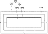
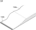
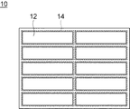
図1は、本発明の実施形態による金型装置を示す図面であり、図2は、図1中の切断部の構成を説明するための平面図であり、図3は、図2中の切断部のカッタを示す斜視図である。図4は、本発明の実施形態による金型装置が加工しようとするパネルを示す平面図である。 1 is a view showing a mold apparatus according to an embodiment of the present invention, FIG. 2 is a plan view for explaining the configuration of a cutting portion in FIG. 1, and FIG. 3 is a cut in FIG. It is a perspective view which shows the cutter of a part. FIG. 4 is a plan view showing a panel to be processed by the mold apparatus according to the embodiment of the present invention.
図1〜図4を参照して、本発明の実施形態による金型装置100は、所定の基板を単位基板に切断する工程を行うことができる。一例として、前記金型装置100は、印刷回路基板(Printed Circuit Board:PCB)の製造のために、マザパネル(Mother Panel)10を切断して複数の単位シートに切断するストリップ工程を行うことができる。これにより、前記金型装置100が加工しようとするパネル10は図4に示すように、複数の単位シート12を含む薄板になる。前記パネル10には、前記金型装置100が前記パネル10を前記単位シート12に切断するためのストリップライン14が設けられる。前記金型装置100は前記ストリップライン14を切断して、前記パネル10から前記単位シート12を製造することができる。
1 to 4, the
前記金型装置100は、ハウジング110と、支持部120と、切断部130と、駆動部140とを含むことができる。一方、図1には前記金型装置100の切断部130が下降し、前記支持部120上に置かれた前記パネル10を切断した様子が示されている。
The
前記ハウジング110は、前記金型装置100の構成を支持及び設置するための構造物であってもよい。前記ハウジング110は、前記支持部120を支持する下部構造体112と、前記切断部130を支持する上部構造体114とを備えることができる。前記上部構造体114は、前記下部構造体112の上部で前記下部構造体112に対向するように配設されることができる。また、前記上部構造体114は前記下部構造体112上で上下に移動可能なように設けられることができる。前記ハウジング110は前記上部構造体114の上下移動を案内するガイド部材116をさらに備えることができる。前記ガイド部材116は、前記下部構造体112と前記上部構造体114とに各々結合され、前記上部構造体114は前記ガイド部材116に沿って上下垂直に移動することができる。
The
前記支持部120は、前記ハウジング110の下部構造体112に固設されることができる。前記支持部120は前記ストリップ工程の際、前記パネル1Oを支持及び固定するテーブルであってもよい。このため、前記支持部120は前記パネル10が置かれる支持面及び前記パネル10を該支持面へと誘導するためのガイドプレートを備えることができる。ここで、前記支持部120は前記支持面にロードされた前記パネル10を水平移動させるように構成されることができる。このため、前記支持部120は前記パネル10を移動させる移送コンベヤ(図示せず)を有することができる。これにより、前記支持部120の支持面上に置かれた前記パネル10は、前記移送コンベヤにより一方向に沿って水平移動することができる。
The
前記切断部130は前記パネル10を切断する構成を有してもよい。前記切断部130は前記支持部120の上部に配設されるように、前記ハウジング110に設けられることができる。ここで、前記切断部130は前記ハウジング110内で上下移動が可能なように設けられることができる。例えば、前記ハウジング110の上部構造体114は前記ガイド部材116に沿って上下に移動し、このような前記ハウジング110の上下移動により、前記切断部130も前記上部構造体114と共に上下に移動することになる。これにより、前記切断部130は前記ストリップ工程の際、前記駆動部140が前記上部構造体114を駆動させることにより、前記ハウジング110の上部構造体114と共に上下に移動することができる。
The
前記切断部130は、コアブロック132及びカッタ134を含むことができる。前記コアブロック132は前記カッタ134を取り囲むように構成されることができる。前記コアブロック132は異なる形状のブロックから構成され、互いに組合わせられて前記カッタ134と前記ハウジング110との間の間隙に対応する形状をなすように提供されることができる。すなわち、前記コアブロック132は多様な形状のブロックから構成され、作業者は、前記ハウジング110と前記カッタ134との間の空間に対応する形状になるように、前記コアブロック132を組合わせることができる。この場合、前記コアブロック132は前記カッタ134と結合され、前記切断部130が前記ハウジング110に設けられている前記切断部130の設置空間に取り付けられるための媒介体として用いられることができる。
The
前記カッタ134は、支持板134aと該支持板134aに設けられるストリッパ134bとを含むことができる。前記支持板134aは前記コアブロック132により固まれて前記ハウジング110に設けられる構成であってもよい。前記ストリッパ134bは、前記ストリップライン14に沿って前記パネル10を切断するための構成であってもよい。このため、前記ストリッパ134bは終端へ行くほど鋭くなる形状を有することができる。前記ストリッパ134bの終端には、前記パネル10の効果的な切断のために複数の切断鋸が設けられることができる。
The
ここで、前記ストリッパ134bは、前記単位シート12各々に対応するストリップライン14を一度に切断するために、1つのストリップライン14に対応する形状を有することができる。例えば、前記パネル10の単位シート12は略四角形状を有し、前記ストリップライン14は前記単位シート12各々の切断のために、前記単位シート12各々を取り囲む形状を有することができる。これにより、前記単位シート12各々を取り囲む1つのストリップライン14は四角の輪形状を有することができる。前記ストリッパ134bは前記ストリップ工程の際、前述のような四角輪形状の個別ストリップライン14に対応して、一度のストリップ工程の際に1つの単位シート12が製造されるように構成することができる。
Here, the
前述のような構造の金型装置100は、次のような方式で前記ストリップ工程を行うことができる。
The
まず、ストリップしようとする前記パネル10に対応するカッタ134を準備する。例えば、前記パネル10には単位シート12各々を取り囲む四角輪形状の個別ストリップライン14が設けられ、前記カッタ134は前記個別ストリップライン14に対応する形状を有するストリッパ134bを有することができる。
First, a
準備した前記カッタ134を前記ハウジング110に取り付ける。例えば、前記ストリッパ134bの備える支持板134aを前記ハウジング110に取り付けることができる。この時、前記支持板134aは前記コアブロック132を介在して、前記ハウジング110に取り付けられることができる。より具体的に、前記カッタ134が取り付けられる前記ハウジング110の装着空間は、多様な大きさ及び形状のストリッパを備えることができるように、前記多様な種類のストリッパに比べて多少大きくなるように調節されることができる。これにより、選択されたカッタ134が前記ハウジング110の上部構造体114により上下に移動するように、前記選択されたカッタ134を前記ハウジング110に取り付けるためには、前記ハウジング110と前記カッタ134との間の空間に前記ハウジング110に前記カッタ134を取り付けるための構成が設けられるべきである。これにより、作業者は、前記カッタ134と前記ハウジング110との間の空間をなくして、前記ハウジング110に前記カッタ134が設けられるように、前記間隙の形状に合うように前記コアブロック132を組合わせることができる。そして、該組合わせた前記コアブロック132を介在して、前記ハウジング110に前記カッタ134を取り付けることができる。この時、前記コアブロック132は前記カッタ134の上下移動を妨害しないような条件で、前記カッタ134の支持板134aを前記ハウジング110に結合することができる。
The
ここで、具体的に示されていないが、前記コアブロック132を前記ハウジング110に結合する方式は、多様な結合方式が挙げられる。例えば、前記コアブロック132と前記ハウジング110とは締め込み方式、ボルト/ナット結合方式、ピン(pin)結合方式、所定の締め付け(clamping)手段を備える方式などが挙げられる。
Here, although not specifically shown, there are various coupling methods for coupling the
前述のように、加工しようとするパネル10に対応するカッタ134を前記ハウジング110に組立てることによって、前述の金型装置100を構成してストリップ工程を行うことができる。まず、前記支持部110に前記パネル10をロード(loading)する。前記支持部110上に置かれた前記パネル10は前記支持部110に固定され、前記駆動部140は前記切断部130を下方へ移動させて、前記パネル10を切断させることができる。ここで、前述のように、前記カッタ134のストリッパ134bは1つのストリップライン14に対応するように構成されるので、前記カッタ134の一度のストリップ工程によって、前記パネル10に設けられた1つの単位シート12が製造されることができる。
As described above, by assembling the
前述のようなストリップ工程を反復行って、前記パネル10を切断して、複数の単位シート12を製造することができる。該製造された単位シート12は後続工程が行われる場所へ移送されることになる。
A plurality of
後に、前述のような構造の金型装置100は製造しようとする単位シート12の形状が変更される場合、前記カッタ134を前記単位シート12のストリップ工程に対応可能なように新たなカッタで交替することによって、前記ストリップ工程を行うことができる。この時、前記新たなカッタの構造が異なるため、該新たなカッタを前記ハウジング110に取り付けるために、前記コアブロック132を再び組合わせることができる。これにより、該再組合わせられた前記コアブロック132を介在して、前記ハウジング110に前記新たなカッタを装着して、前記ストリップ工程を行うことができる。
Later, when the shape of the
前述のように、本発明の実施形態による金型装置100はハウジング110と、パネル10を支持する支持部120と、前記パネル10のストリップライン14に沿って前記パネル10を切断する切断部130と、前記切断部130を駆動する駆動部140とを備えることができる。前記切断部130は前記パネル10の単位シート12の製造のための単位ストリップライン14に対応するカッタ134と、該カッタ134を前記ハウジング110に具備するコアブロック132とを含むことができる。ここで、前記コアブロック132は前記カッタ134の構造によって変化される前記ハウジング110と前記カッタ134との間の間隙の形状に対応するように、その組合が変更されることができる。これにより、本発明による金型装置100は、製造しようとする印刷回路基板のモデルが変更される場合にも、前記カッタを新たなカッタで交替し、該交替されたカッタと前記ハウジング110との間の間隙に対応する構造で前記コアブロック132を組合わせることによって、多様な種類の基板に対してストリップ工程を行うことができる。
As described above, the
また、本発明の実施形態による金型装置100は、前記単位シート12各々の切断のための個別ストリップライン14に対応するストリッパ134bを有するカッタ134を備えることによって、一度に1つの単位シート12を製造するように構成されることができる。この場合、前記ルータビット(Router Bit)で前記ストリップライン14に沿って切断してストリップ工程を行うか、または一般的なバー(bar)構造のストリッパを用いてストリップ工程を行う場合に比べて、ストリップ工程の時間を短縮することができる。これにより、本発明による金型装置100は、印刷回路基板の製造工程時間を短縮することができる。
In addition, the
今回開示された実施の形態はすべての点で例示であって制限的なものではないと考えられるべきである。本発明の範囲は、前記した実施の形態の説明ではなくて特許請求の範囲によって示され、特許請求の範囲と均等の意味及び範囲内でのすべての変更が含まれることが意図される。 The embodiment disclosed this time should be considered as illustrative in all points and not restrictive. The scope of the present invention is shown not by the above description of the embodiments but by the scope of claims, and is intended to include all modifications within the meaning and scope equivalent to the scope of claims.
100 金型装置
110 ハウジング
112 下部構造体
114 上部構造体
116 ガイド部材
120 テーブル
130 切断部
132 コアブロック
134 カッタ
134a 支持板
134b ストリツパ
140 駆動部
DESCRIPTION OF
Claims (7)
ハウジングと、
前記ハウジングに設けられ、前記パネルを支持及び固定する支持部と、
前記ハウジングの上部に設けられ、前記支持部上に置かれた前記パネルのストリップラインに沿って前記パネルを切断する切断部と、
前記切断部を駆動する駆動部とを含み、
前記切断部は、
前記ストリップラインを切断するカッタと、
前記カッタを前記ハウジングに装着させ、互いに組合わせて前記ハウジングと前記カッタとの間の間隙に対応する構造をなすコアブロック
とを含む金型装置。 In a mold apparatus that performs a strip process for manufacturing a unit sheet by cutting a panel,
A housing;
A support portion provided in the housing for supporting and fixing the panel;
A cutting part provided on an upper part of the housing and cutting the panel along a strip line of the panel placed on the support part;
A drive unit for driving the cutting unit,
The cutting part is
A cutter for cutting the stripline;
A mold apparatus comprising: a core block configured to mount the cutter on the housing and combine with each other to form a structure corresponding to a gap between the housing and the cutter.
前記支持部を支持する下部構造体と、
前記下部構造体の上部で前記下部構造体に対向する上部構造体と、
前記下部構造体と前記上部構造体とに各々結合され、前記下部構造体上で前記上部構造体の上下移動を案内するガイド部材とを含み、
前記コアブロックは、前記カッタを前記上部構造体に結合させる請求項1に記載の金型装置。 The housing is
A lower structure that supports the support;
An upper structure facing the lower structure above the lower structure;
A guide member that is coupled to each of the lower structure and the upper structure and guides the vertical movement of the upper structure on the lower structure;
The mold apparatus according to claim 1, wherein the core block connects the cutter to the upper structure.
前記コアブロックを介在して前記ハウジングに取り付けられる支持板と、
前記ストリップラインに対応するように前記支持板の下面に突設されるストリッパ
とを含む請求項1に記載の金型装置。 The cutting part is
A support plate attached to the housing via the core block;
The mold apparatus according to claim 1, further comprising a stripper provided on a lower surface of the support plate so as to correspond to the strip line.
前記ストリッパは、前記四角リング形状に対応する形状を有するように、前記支持板の縁部に沿って設けられる請求項4に記載の金型装置。 The strip line has a square ring shape,
The mold apparatus according to claim 4, wherein the stripper is provided along an edge portion of the support plate so as to have a shape corresponding to the square ring shape.
前記単位シート各々の製造のための個別ストリップラインに対応するリング構造のカッタを準備するステップと、
前記カッタと前記金型ハウジングとの間の間隙に対応する形状がなされるように、コアブロックを組合わせるステップと、
前記コアブロックを介在して、前記金型ハウジングに前記カッタを取り付けるステップと、
前記カッタを上下駆動させて、前記ストリップラインに沿って前記パネルを切断するステップ
とを含む基板切断方法。 A housing, a support provided at a lower portion of the housing, for supporting and fixing the panel, and a panel provided at an upper portion of the housing and cut along the strip line of the panel placed on the support; A strip process for manufacturing a unit sheet using a cutting part,
Providing a ring structure cutter corresponding to an individual strip line for manufacturing each of the unit sheets;
Combining the core blocks so that a shape corresponding to the gap between the cutter and the mold housing is formed;
Attaching the cutter to the mold housing via the core block;
Cutting the panel along the strip line by driving the cutter up and down.
前記ハウジングと前記新たなカッタとの間の間隙に対応する形状がなされるように、前記コアブロックを再び組合わせるステップと、
該再び組合わせられた前記コアブロックを介在して、前記ハウジングに前記新たなカッタを取り付けるステップ
とをさらに含む請求項6に記載の基板切断方法。 When the model of the unit sheet is changed, preparing a new cutter that matches the changed model;
Recombining the core blocks to form a shape corresponding to the gap between the housing and the new cutter;
The substrate cutting method according to claim 6, further comprising a step of attaching the new cutter to the housing through the recombined core block.
Applications Claiming Priority (2)
| Application Number | Priority Date | Filing Date | Title |
|---|---|---|---|
| KR1020100070956A KR20120009116A (en) | 2010-07-22 | 2010-07-22 | Mold apparatus and substrate cutting method using the same |
| KR10-2010-0070956 | 2010-07-22 |
Publications (2)
| Publication Number | Publication Date |
|---|---|
| JP2012024914A true JP2012024914A (en) | 2012-02-09 |
| JP5547046B2 JP5547046B2 (en) | 2014-07-09 |
Family
ID=45546492
Family Applications (1)
| Application Number | Title | Priority Date | Filing Date |
|---|---|---|---|
| JP2010263297A Expired - Fee Related JP5547046B2 (en) | 2010-07-22 | 2010-11-26 | Mold apparatus and substrate cutting method using the same |
Country Status (4)
| Country | Link |
|---|---|
| JP (1) | JP5547046B2 (en) |
| KR (1) | KR20120009116A (en) |
| CN (1) | CN102348329A (en) |
| TW (1) | TW201206274A (en) |
Families Citing this family (4)
| Publication number | Priority date | Publication date | Assignee | Title |
|---|---|---|---|---|
| JP6252098B2 (en) * | 2012-11-01 | 2017-12-27 | 信越化学工業株式会社 | Square mold substrate |
| CN103770156B (en) * | 2014-02-13 | 2015-07-15 | 遂宁市广天电子有限公司 | PCB deboost stamping forming device and method |
| CN109366613A (en) * | 2018-12-21 | 2019-02-22 | 隆扬电子(昆山)有限公司 | Conductive foam die cut method |
| CN109366614A (en) * | 2018-12-21 | 2019-02-22 | 隆扬电子(昆山)有限公司 | The die cut jig of conductive foam item |
Citations (5)
| Publication number | Priority date | Publication date | Assignee | Title |
|---|---|---|---|---|
| US2313801A (en) * | 1941-12-03 | 1943-03-16 | Kenneth W Carll | Cutting die |
| JPH0386499A (en) * | 1989-08-31 | 1991-04-11 | Seikosha Co Ltd | Punching device |
| JPH0627099U (en) * | 1992-09-04 | 1994-04-12 | 株式会社ケンウッド | Printed circuit board divider |
| JPH08141999A (en) * | 1994-11-17 | 1996-06-04 | Daisou Kk | Punch die |
| JP2011016218A (en) * | 2009-06-09 | 2011-01-27 | Frontier:Kk | Cutting apparatus |
-
2010
- 2010-07-22 KR KR1020100070956A patent/KR20120009116A/en not_active Ceased
- 2010-11-10 TW TW99138704A patent/TW201206274A/en unknown
- 2010-11-26 JP JP2010263297A patent/JP5547046B2/en not_active Expired - Fee Related
- 2010-12-13 CN CN2010105865527A patent/CN102348329A/en active Pending
Patent Citations (5)
| Publication number | Priority date | Publication date | Assignee | Title |
|---|---|---|---|---|
| US2313801A (en) * | 1941-12-03 | 1943-03-16 | Kenneth W Carll | Cutting die |
| JPH0386499A (en) * | 1989-08-31 | 1991-04-11 | Seikosha Co Ltd | Punching device |
| JPH0627099U (en) * | 1992-09-04 | 1994-04-12 | 株式会社ケンウッド | Printed circuit board divider |
| JPH08141999A (en) * | 1994-11-17 | 1996-06-04 | Daisou Kk | Punch die |
| JP2011016218A (en) * | 2009-06-09 | 2011-01-27 | Frontier:Kk | Cutting apparatus |
Also Published As
| Publication number | Publication date |
|---|---|
| KR20120009116A (en) | 2012-02-01 |
| JP5547046B2 (en) | 2014-07-09 |
| CN102348329A (en) | 2012-02-08 |
| TW201206274A (en) | 2012-02-01 |
Similar Documents
| Publication | Publication Date | Title |
|---|---|---|
| JP5981791B2 (en) | Breaking device for brittle material substrate | |
| JP5547046B2 (en) | Mold apparatus and substrate cutting method using the same | |
| JP2009137007A (en) | Substrate punching apparatus | |
| CN102107290A (en) | Drilling method and drilling equipment | |
| JP2013043348A (en) | Method and device for dividing brittle plate material | |
| JP6085384B2 (en) | Breaking device for brittle material substrate | |
| CN204800716U (en) | Reliable cutting device of centre gripping | |
| JP5331189B2 (en) | Substrate break device | |
| JP2004022606A (en) | Processing method of metal board and metal board processed by the method | |
| JP6901066B2 (en) | Flexible printed wiring board manufacturing method and flexible printed wiring board manufacturing equipment | |
| CN204800715U (en) | Cutting device of anti -Vibration damage | |
| KR102023453B1 (en) | Apparatus and method for dividing substrate | |
| CN104394650A (en) | Board splitting method for combined printed circuit board finishing component surface mounting | |
| JP6312027B2 (en) | Substrate fixing and replacement method in router processing equipment | |
| CN210579905U (en) | A PCB soldering terminal cutting machine | |
| JP5451720B2 (en) | Substrate break method | |
| TWI659541B (en) | Groove processing device | |
| CN205032758U (en) | Drilling device for circuit board stamp hole | |
| CN222200880U (en) | A punching device for a large-size printed circuit board | |
| JP2010147273A (en) | Master printed circuit board, and methods of manufacturing and inspecting printed circuit board | |
| JP5994447B2 (en) | Magnet piece manufacturing apparatus constituting field pole magnet body and manufacturing method thereof | |
| CN110167270B (en) | Jig and mounting equipment | |
| JP2014019043A (en) | Break device for brittle material substrate | |
| JP4663335B2 (en) | Manufacturing method of electronic circuit unit | |
| CN120002834A (en) | Cutting components and cutting equipment |
Legal Events
| Date | Code | Title | Description |
|---|---|---|---|
| A977 | Report on retrieval |
Free format text: JAPANESE INTERMEDIATE CODE: A971007 Effective date: 20120705 |
|
| A131 | Notification of reasons for refusal |
Free format text: JAPANESE INTERMEDIATE CODE: A131 Effective date: 20120724 |
|
| A601 | Written request for extension of time |
Free format text: JAPANESE INTERMEDIATE CODE: A601 Effective date: 20121024 |
|
| A602 | Written permission of extension of time |
Free format text: JAPANESE INTERMEDIATE CODE: A602 Effective date: 20121029 |
|
| A521 | Request for written amendment filed |
Free format text: JAPANESE INTERMEDIATE CODE: A523 Effective date: 20121116 |
|
| A131 | Notification of reasons for refusal |
Free format text: JAPANESE INTERMEDIATE CODE: A131 Effective date: 20130604 |
|
| A601 | Written request for extension of time |
Free format text: JAPANESE INTERMEDIATE CODE: A601 Effective date: 20130904 |
|
| A602 | Written permission of extension of time |
Free format text: JAPANESE INTERMEDIATE CODE: A602 Effective date: 20130909 |
|
| A601 | Written request for extension of time |
Free format text: JAPANESE INTERMEDIATE CODE: A601 Effective date: 20131004 |
|
| A602 | Written permission of extension of time |
Free format text: JAPANESE INTERMEDIATE CODE: A602 Effective date: 20131009 |
|
| A601 | Written request for extension of time |
Free format text: JAPANESE INTERMEDIATE CODE: A601 Effective date: 20131101 |
|
| A521 | Request for written amendment filed |
Free format text: JAPANESE INTERMEDIATE CODE: A523 Effective date: 20131106 |
|
| A602 | Written permission of extension of time |
Free format text: JAPANESE INTERMEDIATE CODE: A602 Effective date: 20131107 |
|
| RD04 | Notification of resignation of power of attorney |
Free format text: JAPANESE INTERMEDIATE CODE: A7424 Effective date: 20131129 |
|
| TRDD | Decision of grant or rejection written | ||
| A01 | Written decision to grant a patent or to grant a registration (utility model) |
Free format text: JAPANESE INTERMEDIATE CODE: A01 Effective date: 20140415 |
|
| A61 | First payment of annual fees (during grant procedure) |
Free format text: JAPANESE INTERMEDIATE CODE: A61 Effective date: 20140514 |
|
| R150 | Certificate of patent or registration of utility model |
Ref document number: 5547046 Country of ref document: JP Free format text: JAPANESE INTERMEDIATE CODE: R150 |
|
| LAPS | Cancellation because of no payment of annual fees |