JP2010064191A - 加工装置 - Google Patents
加工装置 Download PDFInfo
- Publication number
- JP2010064191A JP2010064191A JP2008232985A JP2008232985A JP2010064191A JP 2010064191 A JP2010064191 A JP 2010064191A JP 2008232985 A JP2008232985 A JP 2008232985A JP 2008232985 A JP2008232985 A JP 2008232985A JP 2010064191 A JP2010064191 A JP 2010064191A
- Authority
- JP
- Japan
- Prior art keywords
- workpiece
- support
- gripping
- ring
- gripping device
- Prior art date
- Legal status (The legal status is an assumption and is not a legal conclusion. Google has not performed a legal analysis and makes no representation as to the accuracy of the status listed.)
- Granted
Links
- 238000003825 pressing Methods 0.000 claims abstract description 27
- 238000005520 cutting process Methods 0.000 claims abstract description 26
- 239000007769 metal material Substances 0.000 abstract description 9
- 239000002699 waste material Substances 0.000 abstract description 7
- 239000002184 metal Substances 0.000 description 17
- 238000003754 machining Methods 0.000 description 12
- 239000000463 material Substances 0.000 description 12
- 238000004519 manufacturing process Methods 0.000 description 6
- 238000011144 upstream manufacturing Methods 0.000 description 6
- 238000013459 approach Methods 0.000 description 4
- 238000000034 method Methods 0.000 description 4
- 230000005484 gravity Effects 0.000 description 2
- 238000005452 bending Methods 0.000 description 1
- 239000002826 coolant Substances 0.000 description 1
- 230000000694 effects Effects 0.000 description 1
- 230000003028 elevating effect Effects 0.000 description 1
- 239000007788 liquid Substances 0.000 description 1
- 238000002360 preparation method Methods 0.000 description 1
- 238000003860 storage Methods 0.000 description 1
- 238000003466 welding Methods 0.000 description 1
Images


Landscapes
- Jigs For Machine Tools (AREA)
- Milling Processes (AREA)
- Machine Tool Positioning Apparatuses (AREA)
Abstract
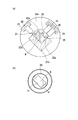
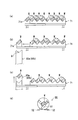
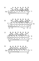
【解決手段】加工装置1は、ワークWを挿通させる貫通孔部15a,15bを有し外歯が周設されたリング状歯車11a,11b、外歯と噛合する複数の歯車17、同一方向に同期して回転し歯車を介してリング状歯車を回動させる複数のモータ18を備える回動装置10a,10bと、直交する二つの支持面を有するワーク支持部21a,21b、二つの支持面にそれぞれ垂直な方向に押圧体を進退させる押圧体駆動装置26を備えリング状歯車と一体回動する把持装置20a,20bと、前端を突出させた状態で把持装置に把持されたワークを回転工具41により加工するNC切削装置40と、ワークの後端を押すワーク送り装置50とを具備する。
【選択図】図1
Description
10,10a,10b 回動装置
11,11a,11b リング状歯車
15,15a,15b 貫通孔部
17 歯車
18 モータ
20,20a,20b 把持装置
21,21a,21b ワーク支持部
22,22a,22b 支持面
25 ピストンロッド(押圧体)
26 油圧シリンダ(押圧体駆動装置)
30 筒体
31 筒体内平面
40 NC切削装置
41 回転工具
50 ワーク送り装置
Claims (3)
- 長尺のワークを挿通させる貫通孔部を有すると共に外歯が周設されたリング状歯車、該リング状歯車の外歯とそれぞれ噛合する複数の歯車、及び、同一方向に同期して回転し複数の前記歯車を介して前記リング状歯車を任意の角度回動させる複数のモータを備える回動装置と、
直交する二つの支持面を有し前記貫通孔部に挿通したワークを支持するワーク支持部、及び、二つの前記支持面の一方に垂直な方向と他方に垂直な方向に沿ってそれぞれ押圧体を進退させる押圧体駆動装置を備え、前記押圧体の前記支持面に向かう前進により前記ワーク支持部に支持されたワークを前記支持面に押圧し把持すると共に、前記リング状歯車と一体回動する把持装置と、
該把持装置から前端を突出させた状態で前記把持装置に把持されたワークを回転工具によりNC加工するNC切削装置と、
前記把持装置による把持が解除されている状態で前記ワーク支持部に支持されているワークの後端を押し、ワークを長軸方向に沿って前進させるワーク送り装置と
を具備することを特徴とする加工装置。 - 二つの前記支持面は、鉛直方向に対して45度傾斜した状態で前記把持装置による把持が解除されているワークを支持する
ことを特徴とする請求項1に記載の加工装置。 - 前記リング状歯車と一体回動する長尺の筒体を更に具備し、
該筒体の内部には、二つの前記支持面と同一の高さで同一角度傾斜している二つの筒体内平面が形成されていることを特徴とする請求項1または請求項2に記載の加工装置。
Priority Applications (1)
| Application Number | Priority Date | Filing Date | Title |
|---|---|---|---|
| JP2008232985A JP5399668B2 (ja) | 2008-09-11 | 2008-09-11 | 加工装置 |
Applications Claiming Priority (1)
| Application Number | Priority Date | Filing Date | Title |
|---|---|---|---|
| JP2008232985A JP5399668B2 (ja) | 2008-09-11 | 2008-09-11 | 加工装置 |
Publications (2)
| Publication Number | Publication Date |
|---|---|
| JP2010064191A true JP2010064191A (ja) | 2010-03-25 |
| JP5399668B2 JP5399668B2 (ja) | 2014-01-29 |
Family
ID=42190226
Family Applications (1)
| Application Number | Title | Priority Date | Filing Date |
|---|---|---|---|
| JP2008232985A Expired - Fee Related JP5399668B2 (ja) | 2008-09-11 | 2008-09-11 | 加工装置 |
Country Status (1)
| Country | Link |
|---|---|
| JP (1) | JP5399668B2 (ja) |
Cited By (2)
| Publication number | Priority date | Publication date | Assignee | Title |
|---|---|---|---|---|
| CN105328500A (zh) * | 2015-12-16 | 2016-02-17 | 山东威达重工股份有限公司 | 内置有自动上卸料机构数控机床及进行工件装卸的方法 |
| CN109176110A (zh) * | 2018-10-12 | 2019-01-11 | 陕西飞机工业(集团)有限公司 | 一种可调联动式三爪导管定位器 |
Citations (9)
| Publication number | Priority date | Publication date | Assignee | Title |
|---|---|---|---|---|
| JPS524399B2 (ja) * | 1972-08-10 | 1977-02-03 | ||
| JPS63272405A (ja) * | 1987-04-28 | 1988-11-09 | Yamazaki Mazak Corp | 複合加工工作機械におけるワ−クの加工方法 |
| JPH106164A (ja) * | 1996-06-17 | 1998-01-13 | Meiki Co Ltd | ロータリテーブルの回転位置決め方法および回転位置決め装置 |
| JPH10156651A (ja) * | 1996-12-04 | 1998-06-16 | Saafu:Kk | 被加工物の固定方法および装置 |
| JP2002301631A (ja) * | 2000-12-26 | 2002-10-15 | Inst Of Physical & Chemical Res | 長尺薄肉形材の加工装置と加工設備 |
| JP2007175790A (ja) * | 2005-12-27 | 2007-07-12 | Ykk Corp | 多面加工機 |
| JP2007229838A (ja) * | 2006-02-28 | 2007-09-13 | Institute Of Physical & Chemical Research | 長尺形材加工装置及び方法 |
| JP2008007299A (ja) * | 2006-06-30 | 2008-01-17 | Nippon Steel Corp | スラブ反転装置 |
| FR2905298A1 (fr) * | 2006-09-06 | 2008-03-07 | Patrick Rangeard | Procede, dispositif et installation permettant de placer et de maintenir en position des pieces, des organes. |
-
2008
- 2008-09-11 JP JP2008232985A patent/JP5399668B2/ja not_active Expired - Fee Related
Patent Citations (9)
| Publication number | Priority date | Publication date | Assignee | Title |
|---|---|---|---|---|
| JPS524399B2 (ja) * | 1972-08-10 | 1977-02-03 | ||
| JPS63272405A (ja) * | 1987-04-28 | 1988-11-09 | Yamazaki Mazak Corp | 複合加工工作機械におけるワ−クの加工方法 |
| JPH106164A (ja) * | 1996-06-17 | 1998-01-13 | Meiki Co Ltd | ロータリテーブルの回転位置決め方法および回転位置決め装置 |
| JPH10156651A (ja) * | 1996-12-04 | 1998-06-16 | Saafu:Kk | 被加工物の固定方法および装置 |
| JP2002301631A (ja) * | 2000-12-26 | 2002-10-15 | Inst Of Physical & Chemical Res | 長尺薄肉形材の加工装置と加工設備 |
| JP2007175790A (ja) * | 2005-12-27 | 2007-07-12 | Ykk Corp | 多面加工機 |
| JP2007229838A (ja) * | 2006-02-28 | 2007-09-13 | Institute Of Physical & Chemical Research | 長尺形材加工装置及び方法 |
| JP2008007299A (ja) * | 2006-06-30 | 2008-01-17 | Nippon Steel Corp | スラブ反転装置 |
| FR2905298A1 (fr) * | 2006-09-06 | 2008-03-07 | Patrick Rangeard | Procede, dispositif et installation permettant de placer et de maintenir en position des pieces, des organes. |
Cited By (2)
| Publication number | Priority date | Publication date | Assignee | Title |
|---|---|---|---|---|
| CN105328500A (zh) * | 2015-12-16 | 2016-02-17 | 山东威达重工股份有限公司 | 内置有自动上卸料机构数控机床及进行工件装卸的方法 |
| CN109176110A (zh) * | 2018-10-12 | 2019-01-11 | 陕西飞机工业(集团)有限公司 | 一种可调联动式三爪导管定位器 |
Also Published As
| Publication number | Publication date |
|---|---|
| JP5399668B2 (ja) | 2014-01-29 |
Similar Documents
| Publication | Publication Date | Title |
|---|---|---|
| KR101642207B1 (ko) | 회전 가공기 및 회전 가공 방법 | |
| JP6582552B2 (ja) | 板材加工システム、及び板材加工方法 | |
| KR101554033B1 (ko) | 차량용 휠 캐리어 브라켓의 탭 가공을 위한 다축 자동 탭핑 장치 | |
| WO2013125550A1 (ja) | 回転加工機 | |
| CN110270839B (zh) | 一种用于加工弹簧夹头的设备 | |
| CN102029545B (zh) | 压弹式自动上料装置 | |
| JP2014073559A (ja) | 竪型工作機械 | |
| AU6356194A (en) | Turning and boring machine | |
| CN209698584U (zh) | 棒料深孔钻自动上下料机 | |
| JP5399668B2 (ja) | 加工装置 | |
| JP5524676B2 (ja) | 加工システムにおけるワーク搬入出装置及びその方法 | |
| JP4473783B2 (ja) | 丸鋸切断機のワーク供給装置およびそのワーク供給方法 | |
| JP5699975B2 (ja) | 運搬システム | |
| KR101071238B1 (ko) | 인풋샤프트의 가공방법 | |
| JPH0691403A (ja) | 工作機械のワーク供給装置 | |
| CN109483328B (zh) | 加工机构及具有其的机加工装置 | |
| JP5580022B2 (ja) | 加工方法及び加工装置 | |
| JP6246850B2 (ja) | リング製造装置 | |
| JP6728373B2 (ja) | ワーク自動搬送機 | |
| CN120885717B (zh) | 一种立式双向多轴组合加工专机及轴类零件的加工方法 | |
| CN114131351B (zh) | 一种筒件加工生产线 | |
| CN220164950U (zh) | 一种环形循环送料装置 | |
| CN117549110B (zh) | 钻铣一体装置 | |
| JP6617025B2 (ja) | 立形旋盤のワーク搬送装置 | |
| CN114774908B (zh) | 一种高速熔覆系统 |
Legal Events
| Date | Code | Title | Description |
|---|---|---|---|
| A621 | Written request for application examination |
Free format text: JAPANESE INTERMEDIATE CODE: A621 Effective date: 20110909 |
|
| A977 | Report on retrieval |
Free format text: JAPANESE INTERMEDIATE CODE: A971007 Effective date: 20130116 |
|
| A131 | Notification of reasons for refusal |
Free format text: JAPANESE INTERMEDIATE CODE: A131 Effective date: 20130129 |
|
| A521 | Request for written amendment filed |
Free format text: JAPANESE INTERMEDIATE CODE: A821 Effective date: 20130328 Free format text: JAPANESE INTERMEDIATE CODE: A523 Effective date: 20130328 |
|
| TRDD | Decision of grant or rejection written | ||
| A01 | Written decision to grant a patent or to grant a registration (utility model) |
Free format text: JAPANESE INTERMEDIATE CODE: A01 Effective date: 20131008 |
|
| A61 | First payment of annual fees (during grant procedure) |
Free format text: JAPANESE INTERMEDIATE CODE: A61 Effective date: 20131024 |
|
| R150 | Certificate of patent or registration of utility model |
Ref document number: 5399668 Country of ref document: JP Free format text: JAPANESE INTERMEDIATE CODE: R150 Free format text: JAPANESE INTERMEDIATE CODE: R150 |
|
| R250 | Receipt of annual fees |
Free format text: JAPANESE INTERMEDIATE CODE: R250 |
|
| R250 | Receipt of annual fees |
Free format text: JAPANESE INTERMEDIATE CODE: R250 |
|
| LAPS | Cancellation because of no payment of annual fees |