JP2010048645A - 濃度測定装置 - Google Patents
濃度測定装置 Download PDFInfo
- Publication number
- JP2010048645A JP2010048645A JP2008212515A JP2008212515A JP2010048645A JP 2010048645 A JP2010048645 A JP 2010048645A JP 2008212515 A JP2008212515 A JP 2008212515A JP 2008212515 A JP2008212515 A JP 2008212515A JP 2010048645 A JP2010048645 A JP 2010048645A
- Authority
- JP
- Japan
- Prior art keywords
- light
- light source
- concentration
- sensor
- concentration measuring
- Prior art date
- Legal status (The legal status is an assumption and is not a legal conclusion. Google has not performed a legal analysis and makes no representation as to the accuracy of the status listed.)
- Granted
Links
- 230000005540 biological transmission Effects 0.000 claims abstract description 12
- CURLTUGMZLYLDI-UHFFFAOYSA-N Carbon dioxide Chemical compound O=C=O CURLTUGMZLYLDI-UHFFFAOYSA-N 0.000 abstract description 22
- 229910002092 carbon dioxide Inorganic materials 0.000 abstract description 11
- 239000001569 carbon dioxide Substances 0.000 abstract description 11
- 238000001514 detection method Methods 0.000 abstract 1
- 239000007789 gas Substances 0.000 description 35
- 238000005259 measurement Methods 0.000 description 13
- 238000000034 method Methods 0.000 description 6
- 238000010586 diagram Methods 0.000 description 2
- 230000002238 attenuated effect Effects 0.000 description 1
- 230000008033 biological extinction Effects 0.000 description 1
- 238000006243 chemical reaction Methods 0.000 description 1
- 239000012141 concentrate Substances 0.000 description 1
- 238000007599 discharging Methods 0.000 description 1
- 238000012986 modification Methods 0.000 description 1
- 230000004048 modification Effects 0.000 description 1
- 239000012466 permeate Substances 0.000 description 1
- 238000002834 transmittance Methods 0.000 description 1
Images

Abstract
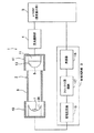
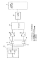
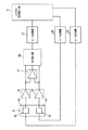
【解決手段】光源7と、光源7からの光を導く気体サンプル室2と、気体サンプル室2から導かれた光源7からの光を受光する赤外線センサ14及び光源7と赤外線センサ14との間に予め定めた波長の光のみを透過させる透過部材15が設けられた受光部41と、赤外線センサ14が受光した光源7からの光の強さに基づいて、気体サンプル室2内の二酸化炭素の濃度を算出するμcom5と、を備えた濃度測定装置1において、赤外線センサの冷接点に分圧回路23を接続して所定のバイアス電圧を印加する。
【選択図】図4
Description
以下、本発明の第1の実施形態に係る濃度測定装置を、図1乃至図7を参照して説明する。
次に、本発明の第2の実施形態を図7を参照して説明する。なお、前述した第1の実施形態と同一部分には、同一符号を付して説明を省略する。
2 気体サンプル室
4 受光回路部
5 マイクロコンピュータ(濃度算出部、バイアス印加手段)
6 測定セル
7 光源
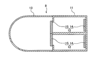
14 赤外線センサ(センサ)
15 透過部材
23 分圧回路(バイアス印加手段)
24 定電圧源
27 減算回路(減算手段)
40 発光部
41 受光部
Claims (6)
- 光源と、前記光源からの光を導く気体サンプル室と、前記気体サンプル室から導かれた前記光源からの光を受光するセンサ及び前記光源と前記センサとの間に予め定めた波長の光のみを透過させる透過部材が設けられた受光部と、前記センサが受光した前記光源からの光の強さに基づいて前記気体サンプル室内の予め定められた気体の濃度を算出する濃度算出部と、を備えた濃度測定装置において、
前記センサに所定のバイアス電圧を印加するバイアス印加手段を備えたことを特徴とする濃度測定装置。 - 前記バイアス印加手段が、予め定めた一定の電圧を供給する定電圧源を備え、前記定電圧源から供給された一定電圧を印加することを特徴とする請求項1に記載の濃度測定装置。
- 前記バイアス印加手段が、前記定電圧源から供給される一定電圧を分圧する抵抗を備え、前記抵抗によって分圧された電圧を印加することを特徴とする請求項2に記載の濃度測定装置。
- 前記受光部には前記センサが複数設けられているとともに、これら複数のセンサにそれぞれ対応する前記透過部材の透過する波長が互いに異なることを特徴とする請求項1乃至3のうちいずれか一項に記載の濃度測定装置。
- 複数の前記センサのうち一方のセンサが受光した前記光源からの光の強さと、他方のセンサが受光した前記光源からの光の強さと、を減算する減算手段を備え、前記バイアス印加手段が、前記減算手段の結果または前記光源消灯時の前記複数のセンサの出力に基づいて、前記一方のセンサと前記他方のセンサとのバイアス電圧が等しくなるように調整することを特徴とする請求項4に記載の濃度測定装置。
- 前記濃度算出部が、前記減算手段の減算結果に基づいて前記気体の濃度を算出することを特徴とする請求項5に記載の濃度測定装置。
Priority Applications (1)
| Application Number | Priority Date | Filing Date | Title |
|---|---|---|---|
| JP2008212515A JP5562538B2 (ja) | 2008-08-21 | 2008-08-21 | 濃度測定装置 |
Applications Claiming Priority (1)
| Application Number | Priority Date | Filing Date | Title |
|---|---|---|---|
| JP2008212515A JP5562538B2 (ja) | 2008-08-21 | 2008-08-21 | 濃度測定装置 |
Publications (2)
| Publication Number | Publication Date |
|---|---|
| JP2010048645A true JP2010048645A (ja) | 2010-03-04 |
| JP5562538B2 JP5562538B2 (ja) | 2014-07-30 |
Family
ID=42065850
Family Applications (1)
| Application Number | Title | Priority Date | Filing Date |
|---|---|---|---|
| JP2008212515A Expired - Fee Related JP5562538B2 (ja) | 2008-08-21 | 2008-08-21 | 濃度測定装置 |
Country Status (1)
| Country | Link |
|---|---|
| JP (1) | JP5562538B2 (ja) |
Citations (10)
| Publication number | Priority date | Publication date | Assignee | Title |
|---|---|---|---|---|
| JPH02130432A (ja) * | 1988-10-25 | 1990-05-18 | Cascadia Technol Corp | ガス分析器 |
| JPH06258144A (ja) * | 1993-03-03 | 1994-09-16 | Casio Comput Co Ltd | 温度センサ |
| JPH0772078A (ja) * | 1993-09-02 | 1995-03-17 | Matsushita Electric Ind Co Ltd | 赤外線式ガスセンサー |
| JPH085552A (ja) * | 1994-06-14 | 1996-01-12 | Tokuyama Corp | 非分散赤外ガス検出装置 |
| JP2710228B2 (ja) * | 1994-08-11 | 1998-02-10 | 日本電気株式会社 | ボロメータ型赤外線検知素子、その駆動方法、および検出用積分回路 |
| JP2000503122A (ja) * | 1996-01-10 | 2000-03-14 | エンジェルハード・センサー・テクノロジーズ・インコーポレイテッド | 受動赤外線分析ガスセンサおよびこれを応用したマルチチャンネル検知装置 |
| JP3133366B2 (ja) * | 1990-04-20 | 2001-02-05 | セントラル リサーチ ラボラトリーズ リミティド | 熱検知装置 |
| JP2002055049A (ja) * | 2000-08-14 | 2002-02-20 | Horiba Ltd | 連続測定装置 |
| JP2002156279A (ja) * | 2000-11-20 | 2002-05-31 | Seiko Epson Corp | サーモパイル型赤外線センサ |
| JP2004198301A (ja) * | 2002-12-19 | 2004-07-15 | Riken Keiki Co Ltd | 赤外線式ガス検出器および赤外線式ガス検知装置 |
-
2008
- 2008-08-21 JP JP2008212515A patent/JP5562538B2/ja not_active Expired - Fee Related
Patent Citations (10)
| Publication number | Priority date | Publication date | Assignee | Title |
|---|---|---|---|---|
| JPH02130432A (ja) * | 1988-10-25 | 1990-05-18 | Cascadia Technol Corp | ガス分析器 |
| JP3133366B2 (ja) * | 1990-04-20 | 2001-02-05 | セントラル リサーチ ラボラトリーズ リミティド | 熱検知装置 |
| JPH06258144A (ja) * | 1993-03-03 | 1994-09-16 | Casio Comput Co Ltd | 温度センサ |
| JPH0772078A (ja) * | 1993-09-02 | 1995-03-17 | Matsushita Electric Ind Co Ltd | 赤外線式ガスセンサー |
| JPH085552A (ja) * | 1994-06-14 | 1996-01-12 | Tokuyama Corp | 非分散赤外ガス検出装置 |
| JP2710228B2 (ja) * | 1994-08-11 | 1998-02-10 | 日本電気株式会社 | ボロメータ型赤外線検知素子、その駆動方法、および検出用積分回路 |
| JP2000503122A (ja) * | 1996-01-10 | 2000-03-14 | エンジェルハード・センサー・テクノロジーズ・インコーポレイテッド | 受動赤外線分析ガスセンサおよびこれを応用したマルチチャンネル検知装置 |
| JP2002055049A (ja) * | 2000-08-14 | 2002-02-20 | Horiba Ltd | 連続測定装置 |
| JP2002156279A (ja) * | 2000-11-20 | 2002-05-31 | Seiko Epson Corp | サーモパイル型赤外線センサ |
| JP2004198301A (ja) * | 2002-12-19 | 2004-07-15 | Riken Keiki Co Ltd | 赤外線式ガス検出器および赤外線式ガス検知装置 |
Also Published As
| Publication number | Publication date |
|---|---|
| JP5562538B2 (ja) | 2014-07-30 |
Similar Documents
| Publication | Publication Date | Title |
|---|---|---|
| US8649012B2 (en) | Optical gas sensor | |
| US8858069B2 (en) | Optical fiber temperature distribution measuring device | |
| JP5176535B2 (ja) | レーザ式ガス分析計 | |
| JP2604754B2 (ja) | 分光光度計 | |
| WO2015119127A1 (ja) | ガス濃度検出装置 | |
| JP6199400B2 (ja) | 光センサを含む空燃比計測システム | |
| JP2006038721A (ja) | ガス濃度検出装置 | |
| US20130120759A1 (en) | Apparatus for measuring a distance | |
| EP1754443A4 (en) | Instrument for measuring information of a living body; STANDARD ELEMENT AND METHOD OF USE OF THE INSTRUMENT FOR MEASURING INFORMATION OF A LIVING BODY | |
| JP5335638B2 (ja) | 煙感知器および火災報知器 | |
| JP5175654B2 (ja) | 気体サンプル室、及び、この気体サンプル室を備える濃度測定装置 | |
| JP2008082862A (ja) | ガス濃度測定装置及びガス濃度測定方法 | |
| JP5562538B2 (ja) | 濃度測定装置 | |
| CN1995977A (zh) | 光纤气体传感器光路自补偿的方法与装置 | |
| JPWO2016021495A1 (ja) | ガス濃度検出装置およびガス濃度検出装置におけるガス濃度の算出方法 | |
| CN113933268B (zh) | 一种光学检测装置及光学检测方法 | |
| JP5161012B2 (ja) | 濃度測定装置 | |
| JP2008292321A (ja) | ガス濃度測定装置 | |
| EP1967842A9 (en) | Method and device for measuring the concentration of exhaust gases of a boiler | |
| KR20150113575A (ko) | Mcu 타입 먼지센서 | |
| JP2010060484A (ja) | 気体セル、気体サンプル室、及び、濃度測定装置 | |
| JP6401606B2 (ja) | 蛍光ガラス線量計読取装置 | |
| JP5562539B2 (ja) | 濃度測定装置 | |
| KR100964145B1 (ko) | 광의 입출력이 일체화된 광감쇄형 센서, 광안정화방법 및 신호처리방법 | |
| JP2009109344A (ja) | 赤外線検出装置 |
Legal Events
| Date | Code | Title | Description |
|---|---|---|---|
| A621 | Written request for application examination |
Free format text: JAPANESE INTERMEDIATE CODE: A621 Effective date: 20110630 |
|
| A977 | Report on retrieval |
Free format text: JAPANESE INTERMEDIATE CODE: A971007 Effective date: 20121105 |
|
| A131 | Notification of reasons for refusal |
Free format text: JAPANESE INTERMEDIATE CODE: A131 Effective date: 20121113 |
|
| A131 | Notification of reasons for refusal |
Free format text: JAPANESE INTERMEDIATE CODE: A131 Effective date: 20130730 |
|
| A521 | Request for written amendment filed |
Free format text: JAPANESE INTERMEDIATE CODE: A523 Effective date: 20130918 |
|
| TRDD | Decision of grant or rejection written | ||
| A01 | Written decision to grant a patent or to grant a registration (utility model) |
Free format text: JAPANESE INTERMEDIATE CODE: A01 Effective date: 20140520 |
|
| A61 | First payment of annual fees (during grant procedure) |
Free format text: JAPANESE INTERMEDIATE CODE: A61 Effective date: 20140611 |
|
| R150 | Certificate of patent or registration of utility model |
Ref document number: 5562538 Country of ref document: JP Free format text: JAPANESE INTERMEDIATE CODE: R150 |
|
| R250 | Receipt of annual fees |
Free format text: JAPANESE INTERMEDIATE CODE: R250 |
|
| R250 | Receipt of annual fees |
Free format text: JAPANESE INTERMEDIATE CODE: R250 |
|
| R250 | Receipt of annual fees |
Free format text: JAPANESE INTERMEDIATE CODE: R250 |
|
| R250 | Receipt of annual fees |
Free format text: JAPANESE INTERMEDIATE CODE: R250 |
|
| R250 | Receipt of annual fees |
Free format text: JAPANESE INTERMEDIATE CODE: R250 |
|
| R250 | Receipt of annual fees |
Free format text: JAPANESE INTERMEDIATE CODE: R250 |
|
| LAPS | Cancellation because of no payment of annual fees |