JP2010040188A - 加熱調理器 - Google Patents
加熱調理器 Download PDFInfo
- Publication number
- JP2010040188A JP2010040188A JP2008198160A JP2008198160A JP2010040188A JP 2010040188 A JP2010040188 A JP 2010040188A JP 2008198160 A JP2008198160 A JP 2008198160A JP 2008198160 A JP2008198160 A JP 2008198160A JP 2010040188 A JP2010040188 A JP 2010040188A
- Authority
- JP
- Japan
- Prior art keywords
- circuit component
- component group
- cooling fan
- heat sink
- duct
- Prior art date
- Legal status (The legal status is an assumption and is not a legal conclusion. Google has not performed a legal analysis and makes no representation as to the accuracy of the status listed.)
- Granted
Links
Images


Classifications
-
- Y—GENERAL TAGGING OF NEW TECHNOLOGICAL DEVELOPMENTS; GENERAL TAGGING OF CROSS-SECTIONAL TECHNOLOGIES SPANNING OVER SEVERAL SECTIONS OF THE IPC; TECHNICAL SUBJECTS COVERED BY FORMER USPC CROSS-REFERENCE ART COLLECTIONS [XRACs] AND DIGESTS
- Y02—TECHNOLOGIES OR APPLICATIONS FOR MITIGATION OR ADAPTATION AGAINST CLIMATE CHANGE
- Y02P—CLIMATE CHANGE MITIGATION TECHNOLOGIES IN THE PRODUCTION OR PROCESSING OF GOODS
- Y02P10/00—Technologies related to metal processing
- Y02P10/25—Process efficiency
Landscapes
- Induction Heating Cooking Devices (AREA)
Abstract
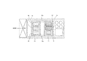
【解決手段】 ダクト7吸気側に配置の冷却ファン5から冷却風がダクト7内に供給、冷却ファン5近傍に配置されたIGBT8a〜cが取付いた冷却風の通過しやすいヒートシンクa10と配線基板15とスペーサー14a、bに供給、発熱量総量が多いIGBT8a〜cとヒートシンクa10を冷却し、冷却風はダクト7に覆われた空間を通過するため分散せず次部品へ到達する。その後、ヒートシンクa10と配線基板15とスペーサー14a、bを通過した冷却風がIGBT8d、8eとダイオードブリッジ9が取付いたヒートシンクa11と、配線基板15とスペーサー14a、bに供給、発熱量総量が少ないIGBT8d、8eとダイオードブリッジ9とヒートシンクb11を冷却する。
【選択図】 図3
Description
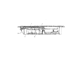
図1はこの発明の実施の形態1における加熱調理器の上面図であり、図2はこの発明の実施の形態1における加熱調理器の断面図である。
図1および図2において、1は被加熱物を入れた容器を載置可能な天板、2は天板1の外周に設けられた天板フレームであり、シリコン接着剤にて天板1と接着されている。3は加熱調理器の本体ケースである。4は天板1の下方に配設された被加熱物を加熱するための加熱コイル、5は冷却風を供給する冷却ファン、6は加熱コイル4を駆動する制御部、7は冷却ファン5と制御部6を連続的に覆うように設けられたダクトであり、これら加熱コイル4、冷却ファン5、制御部6及びダクト7はそれぞれ本体ケース3に収容されている。
0、IGBT8d、IGBT8e、ダイオードブリッジ9を取付けたヒートシンクb11、チョークコイル12、電解コンデンサ13a〜13dが配線基板15の上面に搭載されて、制御部6が構成されている。
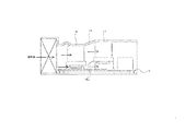
図6はこの発明の実施の形態2における冷却ファンと制御部とダクトの構成を示す上面図、図7はこの発明の実施の形態2における冷却ファンと制御部とダクトの構成を示す側面図である。なお、上述の実施の形態1と同一の部分にはこれと同じ符号を付して説明を省略する。
2 天板フレーム
3 本体ケース
4 加熱コイル
5 冷却ファン
6 制御部
7 ダクト
8a、8b、8c、8d IGBT
9 ダイオードブリッジ
10 ヒートシンクa
11 ヒートシンクb
12 チョークコイル
13a、13b、13c、13d 電解コンデンサ
14a、14b スペーサー
15 配線基板
16a、16b 放熱板
17 ダクト
18a、18b 段付スペーサー
Claims (4)
- 被加熱物を入れた容器が載置可能な天板と、
前記天板の下方に配設された複数の電磁誘導加熱部と、
前記複数の電磁誘導加熱部へ電流を供給する制御部と、
前記制御部へ冷却風を供給する冷却ファンと、
前記冷却ファンの冷却風を上流の吸気側から下流の排気側まで案内するダクトと、を備え、
前記制御部は、発熱量の総量が多い第1の回路部品グループを取り付けた放熱量の小さい放熱部品と、発熱量の総量が少ない第2の回路部品グループを取り付けた放熱量の大きい放熱部品とを配線基板上に配置してなり、
前記ダクトは、前記冷却ファンと前記制御部を連続的に覆うように設け、前記冷却ファンは、前記ダクトの吸気側に配置し、前記第1の回路部品グループは前記冷却ファンに近い位置に配置し、前記第2の回路部品グループはその第1の回路部品から下流側位置に配置したことを特徴とする加熱調理器。 - 前記第1の回路部品グループと前記第2の回路部品グループは、絶縁性の保持部品を介して前記配線基板に取付けられていることを特徴とする請求項1記載の加熱調理器。
- 前記保持部品は、前記第1の回路部品グループと前記第2の回路部品グループと前記配線基板との間に前記冷却ファンの冷却風を導通可能とする空間を設けていることを特徴とする請求項1〜請求項2のいずれかに記載の加熱調理器。
- 前記第1の回路部品グループと前記第2の回路部品グループは、前記配線基板までの対向間隔を互いに異なるようにしたことを特徴とする請求項1〜請求項3のいずれかに記載の加熱調理器。
Priority Applications (1)
| Application Number | Priority Date | Filing Date | Title |
|---|---|---|---|
| JP2008198160A JP5078794B2 (ja) | 2008-07-31 | 2008-07-31 | 加熱調理器 |
Applications Claiming Priority (1)
| Application Number | Priority Date | Filing Date | Title |
|---|---|---|---|
| JP2008198160A JP5078794B2 (ja) | 2008-07-31 | 2008-07-31 | 加熱調理器 |
Publications (2)
| Publication Number | Publication Date |
|---|---|
| JP2010040188A true JP2010040188A (ja) | 2010-02-18 |
| JP5078794B2 JP5078794B2 (ja) | 2012-11-21 |
Family
ID=42012547
Family Applications (1)
| Application Number | Title | Priority Date | Filing Date |
|---|---|---|---|
| JP2008198160A Expired - Fee Related JP5078794B2 (ja) | 2008-07-31 | 2008-07-31 | 加熱調理器 |
Country Status (1)
| Country | Link |
|---|---|
| JP (1) | JP5078794B2 (ja) |
Cited By (4)
| Publication number | Priority date | Publication date | Assignee | Title |
|---|---|---|---|---|
| JP2011210388A (ja) * | 2010-03-29 | 2011-10-20 | Mitsubishi Electric Corp | 誘導加熱調理器 |
| JP2014187042A (ja) * | 2014-06-04 | 2014-10-02 | Mitsubishi Electric Corp | 誘導加熱調理器 |
| JP2016178208A (ja) * | 2015-03-20 | 2016-10-06 | 日本電気株式会社 | ヒートシンク、放熱構造、冷却構造及び装置 |
| JP2018147568A (ja) * | 2017-03-01 | 2018-09-20 | 三菱電機株式会社 | 加熱調理器 |
Citations (5)
| Publication number | Priority date | Publication date | Assignee | Title |
|---|---|---|---|---|
| JPS61129349U (ja) * | 1985-02-01 | 1986-08-13 | ||
| JPH02168697A (ja) * | 1988-09-09 | 1990-06-28 | Hitachi Ltd | 電子機器の冷却装置 |
| JP2004087305A (ja) * | 2002-08-27 | 2004-03-18 | Mitsubishi Electric Corp | 誘導加熱調理器 |
| JP2007073454A (ja) * | 2005-09-09 | 2007-03-22 | Hitachi Appliances Inc | 誘導加熱調理器 |
| JP2007172860A (ja) * | 2005-12-19 | 2007-07-05 | Matsushita Electric Ind Co Ltd | 誘導加熱調理器 |
-
2008
- 2008-07-31 JP JP2008198160A patent/JP5078794B2/ja not_active Expired - Fee Related
Patent Citations (5)
| Publication number | Priority date | Publication date | Assignee | Title |
|---|---|---|---|---|
| JPS61129349U (ja) * | 1985-02-01 | 1986-08-13 | ||
| JPH02168697A (ja) * | 1988-09-09 | 1990-06-28 | Hitachi Ltd | 電子機器の冷却装置 |
| JP2004087305A (ja) * | 2002-08-27 | 2004-03-18 | Mitsubishi Electric Corp | 誘導加熱調理器 |
| JP2007073454A (ja) * | 2005-09-09 | 2007-03-22 | Hitachi Appliances Inc | 誘導加熱調理器 |
| JP2007172860A (ja) * | 2005-12-19 | 2007-07-05 | Matsushita Electric Ind Co Ltd | 誘導加熱調理器 |
Cited By (4)
| Publication number | Priority date | Publication date | Assignee | Title |
|---|---|---|---|---|
| JP2011210388A (ja) * | 2010-03-29 | 2011-10-20 | Mitsubishi Electric Corp | 誘導加熱調理器 |
| JP2014187042A (ja) * | 2014-06-04 | 2014-10-02 | Mitsubishi Electric Corp | 誘導加熱調理器 |
| JP2016178208A (ja) * | 2015-03-20 | 2016-10-06 | 日本電気株式会社 | ヒートシンク、放熱構造、冷却構造及び装置 |
| JP2018147568A (ja) * | 2017-03-01 | 2018-09-20 | 三菱電機株式会社 | 加熱調理器 |
Also Published As
| Publication number | Publication date |
|---|---|
| JP5078794B2 (ja) | 2012-11-21 |
Similar Documents
| Publication | Publication Date | Title |
|---|---|---|
| CN111327208B (zh) | 具散热机制的逆变器装置 | |
| US9192079B2 (en) | Power electronic module cooling system and method | |
| JP5655873B2 (ja) | インバータ装置 | |
| JP6072985B1 (ja) | 電子機器 | |
| JP6315091B2 (ja) | 冷却器及び冷却器の固定方法 | |
| JP5712760B2 (ja) | 誘導加熱調理器 | |
| JP5980537B2 (ja) | 最適な構造を備えた可変速駆動装置 | |
| KR101927742B1 (ko) | 유도 가열 조리기기 | |
| JP2008060430A (ja) | 電力変換装置 | |
| JPH0213266A (ja) | インバータ装置 | |
| JP2011067045A (ja) | インバータ装置 | |
| JP5078794B2 (ja) | 加熱調理器 | |
| JP5716598B2 (ja) | 電源装置 | |
| CN103095100A (zh) | 开关调节器及带有该开关调节器的电源装置 | |
| KR20180070270A (ko) | 인버터 방열구조 | |
| JP2006210516A (ja) | 電子機器の冷却構造 | |
| JP6652467B2 (ja) | 電力変換装置および電力変換装置を搭載した鉄道車両 | |
| KR102445246B1 (ko) | 전력 변환 장치 | |
| JP2010088153A (ja) | 電子機器 | |
| JP2013252006A (ja) | モータ駆動装置及びそれを備えた空気調和機 | |
| JP6213356B2 (ja) | 電源装置 | |
| JP5419764B2 (ja) | 誘導加熱調理器 | |
| JP7316193B2 (ja) | 電力変換装置 | |
| CN223694048U (zh) | 电路板及电源模块 | |
| CN223283208U (zh) | 空调器的电控板和空调器 |
Legal Events
| Date | Code | Title | Description |
|---|---|---|---|
| A621 | Written request for application examination |
Free format text: JAPANESE INTERMEDIATE CODE: A621 Effective date: 20100824 |
|
| A977 | Report on retrieval |
Free format text: JAPANESE INTERMEDIATE CODE: A971007 Effective date: 20120509 |
|
| RD03 | Notification of appointment of power of attorney |
Free format text: JAPANESE INTERMEDIATE CODE: A7423 Effective date: 20120511 |
|
| A131 | Notification of reasons for refusal |
Free format text: JAPANESE INTERMEDIATE CODE: A131 Effective date: 20120515 |
|
| RD04 | Notification of resignation of power of attorney |
Free format text: JAPANESE INTERMEDIATE CODE: A7424 Effective date: 20120517 |
|
| A521 | Request for written amendment filed |
Free format text: JAPANESE INTERMEDIATE CODE: A523 Effective date: 20120709 |
|
| TRDD | Decision of grant or rejection written | ||
| A01 | Written decision to grant a patent or to grant a registration (utility model) |
Free format text: JAPANESE INTERMEDIATE CODE: A01 Effective date: 20120731 |
|
| A01 | Written decision to grant a patent or to grant a registration (utility model) |
Free format text: JAPANESE INTERMEDIATE CODE: A01 |
|
| A61 | First payment of annual fees (during grant procedure) |
Free format text: JAPANESE INTERMEDIATE CODE: A61 Effective date: 20120828 |
|
| FPAY | Renewal fee payment (event date is renewal date of database) |
Free format text: PAYMENT UNTIL: 20150907 Year of fee payment: 3 |
|
| R150 | Certificate of patent or registration of utility model |
Ref document number: 5078794 Country of ref document: JP Free format text: JAPANESE INTERMEDIATE CODE: R150 Free format text: JAPANESE INTERMEDIATE CODE: R150 |
|
| R250 | Receipt of annual fees |
Free format text: JAPANESE INTERMEDIATE CODE: R250 |
|
| R250 | Receipt of annual fees |
Free format text: JAPANESE INTERMEDIATE CODE: R250 |
|
| R250 | Receipt of annual fees |
Free format text: JAPANESE INTERMEDIATE CODE: R250 |
|
| R250 | Receipt of annual fees |
Free format text: JAPANESE INTERMEDIATE CODE: R250 |
|
| R250 | Receipt of annual fees |
Free format text: JAPANESE INTERMEDIATE CODE: R250 |
|
| R250 | Receipt of annual fees |
Free format text: JAPANESE INTERMEDIATE CODE: R250 |
|
| R250 | Receipt of annual fees |
Free format text: JAPANESE INTERMEDIATE CODE: R250 |
|
| LAPS | Cancellation because of no payment of annual fees |