JP2009021470A - Circuit substrate - Google Patents
Circuit substrate Download PDFInfo
- Publication number
- JP2009021470A JP2009021470A JP2007184071A JP2007184071A JP2009021470A JP 2009021470 A JP2009021470 A JP 2009021470A JP 2007184071 A JP2007184071 A JP 2007184071A JP 2007184071 A JP2007184071 A JP 2007184071A JP 2009021470 A JP2009021470 A JP 2009021470A
- Authority
- JP
- Japan
- Prior art keywords
- layers
- fibers
- prepreg
- circuit board
- core layer
- Prior art date
- Legal status (The legal status is an assumption and is not a legal conclusion. Google has not performed a legal analysis and makes no representation as to the accuracy of the status listed.)
- Pending
Links
Images


Abstract
Description
本発明は回路基板に関し、特に、プリプレグが複数積層して構成される回路基板に関する。 The present invention relates to a circuit board, and more particularly to a circuit board configured by stacking a plurality of prepregs.
パッケージ基板、放熱部品、コネクタ、CPU(Central Processing Unit:中央処理装置)およびLSI(Large Scale Integrated circuit)などの実装部品を担持する基板として、絶縁樹脂で構成される回路基板が利用されている。回路基板に絶縁樹脂を利用することで、実装部品を電気的に接続する伝送線路(配線)や、層間を接続するビアやスルーホールなどの導体間ならびに実装部品の絶縁を行うことができる。 A circuit board made of an insulating resin is used as a board for carrying mounting parts such as a package board, a heat dissipation component, a connector, a CPU (Central Processing Unit) and an LSI (Large Scale Integrated circuit). By using the insulating resin for the circuit board, it is possible to insulate the transmission line (wiring) for electrically connecting the mounted components, the conductors such as vias and through holes connecting the layers, and the mounted components.
ところが、絶縁樹脂自体は、弾性率が低く、実装部品を支える構造用材料としては強度が不足しているため、弾性率の高いガラスファイバのような繊維で構成された織布に絶縁樹脂を含浸させることで高い耐久性を実現させたFRP(Fiber Reinforced Plastic)が一般的に利用されている。さらに、FRPを多層化する際に繊維方向を揃えることで、安定した基板特性を実現させることができる。 However, the insulating resin itself has a low elastic modulus and is insufficient in strength as a structural material to support the mounting component. Therefore, the insulating resin is impregnated with a woven fabric made of fibers such as glass fiber with a high elastic modulus. In general, FRP (Fiber Reinforced Plastic), which achieves high durability by being used, is used. Furthermore, stable substrate characteristics can be realized by aligning the fiber direction when multilayering FRP.
しかし、FRPでは、繊維の配向に依存して回路基板に強度の斑が生じる。このため、例えば、熱が印加されることにより発生した応力は、クロスで補強されていない方向、つまり回路基板の強度が弱い方向へ開放されて、回路基板にねじれによる変形が発生することにより、回路基板の信頼性を著しく低下させてしまう。 However, in FRP, depending on the orientation of the fibers, unevenness of strength occurs on the circuit board. For this reason, for example, the stress generated by the application of heat is released in a direction not reinforced by the cross, that is, in a direction where the strength of the circuit board is weak, and the circuit board undergoes deformation due to twisting, The reliability of the circuit board is significantly reduced.
そこで、FRPの最大の特徴である高い弾性率を保ちつつ、繊維の配向に依存したねじれによる回路基板の変形を抑制させるために、回路基板の内層に繊維の配向方向が異なるFRPを交互に配置することなど(例えば、特許文献1,2参照)がこれまでに提案されてきた。
しかし、回路基板の内層に繊維の配向方向が異なるFRPを交互に配置することによって、ノウハウとして基板製造メーカで蓄積した高精度な位置合わせ(スケーリング)技術の適用が困難となってしまうため、上記従来技術は実用に至っていないという問題点があった。 However, by alternately arranging FRPs having different fiber orientation directions on the inner layer of the circuit board, it becomes difficult to apply high-precision alignment (scaling) technology accumulated by the board manufacturer as know-how. There has been a problem that the prior art has not been put into practical use.
本発明はこのような点に鑑みてなされたものであり、弾性率を保ちつつ、ねじれの発生を抑制でき、さらに、現状の基板製造時におけるスケーリング技術をそのまま適用して、容易に形成できる回路基板を提供することを目的とする。 The present invention has been made in view of the above points, and can suppress the occurrence of twist while maintaining the elastic modulus, and can be easily formed by applying the current scaling technique at the time of manufacturing a substrate as it is. An object is to provide a substrate.
本発明では上記課題を解決するために、図1に示すように、繊維11aに樹脂11bを含浸させたプリプレグ11が複数積層された中間層12と、中間層12のねじれ方向に配向させた繊維14aに樹脂14bを含浸させたプリプレグ14と、を有し、中間層12は、プリプレグ14に挟持されていることを特徴とする回路基板10が提供される。 In the present invention, in order to solve the above problem, as shown in FIG. 1, an intermediate layer 12 in which a plurality of prepregs 11 in which fibers 11a are impregnated with a resin 11b are laminated, and fibers in which the intermediate layer 12 is oriented in the twist direction And a prepreg 14 in which a resin 14b is impregnated in 14a, and the intermediate layer 12 is sandwiched between the prepregs 14 to provide a circuit board 10.
このような回路基板によれば、繊維に樹脂を含浸させたプリプレグが複数積層された中間層が、中間層のねじれ方向に配向させた繊維に樹脂を含浸させたプリプレグに挟持されて、中間層の最上および最下に形成されたプリプレグと中間層とに生じる応力を相殺するようになる。 According to such a circuit board, an intermediate layer in which a plurality of prepregs in which fibers are impregnated with a resin is sandwiched between prepregs in which fibers that are oriented in the twist direction of the intermediate layer are impregnated with a resin, The stress generated in the prepreg formed on the uppermost and lowermost layers and the intermediate layer is offset.
本発明では、繊維に樹脂を含浸させたプリプレグが複数積層された中間層が、中間層のねじれ方向に配向させた繊維に樹脂を含浸させたプリプレグに挟持されて、中間層の最上および最下に形成されたプリプレグと中間層とに生じる応力を相殺するようにした。これにより、現状の基板製造時におけるスケーリング技術をそのまま適用し、かつ回路基板に生じるねじれによる変形を大幅に抑制することができる。 In the present invention, an intermediate layer in which a plurality of prepregs in which fibers are impregnated with a resin is sandwiched between prepregs in which fibers are impregnated in a twisted direction of the intermediate layer, and the uppermost and lowermost layers of the intermediate layer are sandwiched. The stress generated in the prepreg and the intermediate layer formed on each other was offset. As a result, the current scaling technique at the time of board manufacture can be applied as it is, and deformation due to twist generated in the circuit board can be significantly suppressed.
以下、本発明の実施の形態を、図面を参照して詳細に説明する。但し、本発明の技術的範囲はこれらの実施の形態に限定されない。
本実施の概要について図面を参照して説明し、その後に、本発明の概要に基づいた実施の形態について、同様に図面を参照して説明する。
Hereinafter, embodiments of the present invention will be described in detail with reference to the drawings. However, the technical scope of the present invention is not limited to these embodiments.
An outline of the present embodiment will be described with reference to the drawings, and then an embodiment based on the outline of the present invention will be described with reference to the drawings.
では、本発明の概要について図1を用いて以下に説明する。
図1は、本発明の概要図である。
回路基板10は、図1(A)に示すように、中間層12と、中間層12の最上および最下の表層に形成された一対のプリプレグ14とによって構成されている。なお、図1(A)では、便宜上、中間層12とプリプレグ14とを離して示しているが、実際に中間層12とプリプレグ14とを積層させた回路基板10の断面図は、図1(B)に示すとおり、中間層12の最上および最下の表層に一対のプリプレグ14が形成されている。
The outline of the present invention will be described below with reference to FIG.
FIG. 1 is a schematic diagram of the present invention.
As shown in FIG. 1A, the circuit board 10 includes an intermediate layer 12 and a pair of prepregs 14 formed on the uppermost and lowermost surface layers of the intermediate layer 12. In FIG. 1A, for convenience, the intermediate layer 12 and the prepreg 14 are shown separated from each other, but a cross-sectional view of the circuit board 10 in which the intermediate layer 12 and the prepreg 14 are actually stacked is shown in FIG. As shown in B), a pair of prepregs 14 are formed on the uppermost and lowermost surface layers of the intermediate layer 12.
中間層12は、プリプレグ11を複数積層して構成させている。なお、プリプレグ11は、配向させた繊維11aを樹脂11bで含浸させており、このプリプレグ11の積層では、プリプレグ11同士の繊維11aが重なるようにしている。 The intermediate layer 12 is formed by stacking a plurality of prepregs 11. The prepreg 11 is impregnated with the oriented fibers 11a with the resin 11b, and in the lamination of the prepregs 11, the fibers 11a of the prepregs 11 overlap each other.
このような構成である中間層12に対して応力が生じた場合、中間層12は繊維11aの配向方向に対して強度を有するため、応力は繊維11aが配向させていない箇所に集中してしまう。例えば、図1(A)では、中間層12は繊維11aの配向方向に対して強度を有するために、中間層12に生じた応力は図中の「ねじれ方向13」に集中して、中間層12にねじれが生じて、歪みの原因となってしまう。 When stress is generated on the intermediate layer 12 having such a configuration, the intermediate layer 12 has strength with respect to the orientation direction of the fibers 11a, so that the stress is concentrated on a portion where the fibers 11a are not oriented. . For example, in FIG. 1A, since the intermediate layer 12 has strength with respect to the orientation direction of the fibers 11a, the stress generated in the intermediate layer 12 is concentrated in the “twist direction 13” in the figure, Twist occurs in 12 and causes distortion.
一方、プリプレグ14は、プリプレグ11と同様に、配向させた繊維14aを樹脂14bで含浸させて構成させており、さらに、プリプレグ14の繊維14aはねじれ方向13と同方向に配向させている。ねじれ方向13と同方向に繊維14aを配向させると、中間層12の説明で触れたように、プリプレグ14に応力が生じると、プリプレグ14はねじれ方向13に沿った、繊維14aの配向方向に対して強度を有するようになり、そして、応力は繊維14aが配向させていない箇所に集中してしまう。すなわち、プリプレグ14に生じた応力は、中間層12の繊維11aの配向と同方向に集中し、プリプレグ14にねじれが生じてしまう。 On the other hand, the prepreg 14, similarly to the prepreg 11, is configured by impregnating the oriented fibers 14 a with the resin 14 b, and the fibers 14 a of the prepreg 14 are oriented in the same direction as the twist direction 13. When the fibers 14 a are oriented in the same direction as the twist direction 13, as mentioned in the description of the intermediate layer 12, when stress is generated in the prepreg 14, the prepreg 14 is aligned with the orientation direction of the fibers 14 a along the twist direction 13. Thus, the stress is concentrated, and the stress is concentrated on the portion where the fiber 14a is not oriented. That is, the stress generated in the prepreg 14 is concentrated in the same direction as the orientation of the fibers 11a of the intermediate layer 12, and the prepreg 14 is twisted.
したがって、中間層12の最上および最下の表層に、繊維14aが配向させたプリプレグ14をそれぞれ形成することによって、回路基板10のねじれを制御することができる。すなわち、中間層12の最上および最下の表層に、中間層12のねじれ方向13に沿って繊維14aが配向させたプリプレグ14をそれぞれ形成することによって、回路基板10上の実装部品の熱などにより、中間層12とプリプレグ14とに生じた応力を相殺させることができ、回路基板10へのねじれを抑制することができる。また、このような構成を得るために、中間層12はプリプレグ11を同方向に積層しただけであり、ねじれ方向13と同方向に配向させた繊維14aを備える一対のプリプレグ14を中間層12の表層に形成しただけであるため、現状の製造プロセスをそのまま利用でき、高精度な位置合わせも可能となる。 Therefore, the twist of the circuit board 10 can be controlled by forming the prepregs 14 in which the fibers 14a are oriented on the uppermost layer and the lowermost surface layer of the intermediate layer 12, respectively. That is, by forming the prepregs 14 in which the fibers 14a are oriented along the twist direction 13 of the intermediate layer 12 on the uppermost and lowermost surface layers of the intermediate layer 12, respectively, due to the heat of the mounted components on the circuit board 10 The stress generated in the intermediate layer 12 and the prepreg 14 can be offset, and the twist to the circuit board 10 can be suppressed. Further, in order to obtain such a configuration, the intermediate layer 12 is simply formed by laminating the prepregs 11 in the same direction, and a pair of prepregs 14 including fibers 14 a oriented in the same direction as the twist direction 13 are formed on the intermediate layer 12. Since it is only formed on the surface layer, the current manufacturing process can be used as it is, and high-precision alignment is also possible.
次に実施の形態について図2〜図5を用いて説明する。
本実施の形態では、本発明の概要に基づいた実施例1〜実施例3を例に挙げて説明する。なお、本実施の形態において用いられるプリプレグを、本発明の概要で触れたように、配向させた繊維に樹脂を含浸させて構成させているとする。
Next, an embodiment will be described with reference to FIGS.
In the present embodiment, examples 1 to 3 based on the outline of the present invention will be described as examples. It is assumed that the prepreg used in the present embodiment is configured by impregnating a resin into an oriented fiber as described in the outline of the present invention.
(実施例1)
実施例1では、直交する2方向に繊維を配向させたプリプレグを利用した場合を例に挙げて説明する。
Example 1
In Example 1, a case where a prepreg in which fibers are oriented in two orthogonal directions is used will be described as an example.
図2は、本実施の形態における実施例1の斜視および断面模式図である。
回路基板20は、図2(A)に示すように、コア層21を中心として、コア層21の上下にビルドアップ層22,23、最表層24,25が順に形成された鏡面構造が構成されている。なお、図2(A)では、便宜上、コア層21、ビルドアップ層22,23および最表層24,25を離して示しているが、実際にコア層21、ビルドアップ層22,23および最表層24,25を積層させた回路基板20の断面図は、図2(B)に示すとおり、コア層21を中心として、コア層21の上下にビルドアップ層22,23および最表層24,25が順に形成されている。
FIG. 2 is a perspective view and a schematic cross-sectional view of Example 1 in the present embodiment.
As shown in FIG. 2A, the circuit board 20 has a mirror structure in which build-up layers 22 and 23 and outermost layers 24 and 25 are formed in order on the top and bottom of the core layer 21 with the core layer 21 as the center. ing. In FIG. 2A, for convenience, the core layer 21, the build-up layers 22 and 23, and the outermost layers 24 and 25 are shown separated, but the core layer 21, the build-up layers 22 and 23, and the outermost layer are actually shown. As shown in FIG. 2B, the cross-sectional view of the circuit board 20 in which the layers 24 and 25 are laminated includes the build-up layers 22 and 23 and the outermost layers 24 and 25 above and below the core layer 21 with the core layer 21 at the center. It is formed in order.
コア層21はプリプレグ27で構成されていて、プリプレグ27は繊維27aに樹脂27bを含浸させて構成させている。このようなコア層21には、所望の回路配線などが形成される。なお、プリプレグ27の繊維27aはプリプレグ27の縦および横の各辺にそれぞれ平行な2方向に配向させている。また、繊維27aに適用される材料としては、ガラスクロス、アラミドまたは炭素繊維などが考えられる。 The core layer 21 is constituted by a prepreg 27, and the prepreg 27 is constituted by impregnating a fiber 27a with a resin 27b. In such a core layer 21, a desired circuit wiring or the like is formed. The fibers 27a of the prepreg 27 are oriented in two directions parallel to the vertical and horizontal sides of the prepreg 27, respectively. Further, as a material applied to the fiber 27a, glass cloth, aramid, carbon fiber, or the like can be considered.
ビルドアップ層22,23は、コア層21の上下にそれぞれ形成されている。また、ビルドアップ層22,23はそれぞれ2層のプリプレグ27で構成されている。なお、プリプレグ27同士の繊維27aがそれぞれ重なるように、コア層21およびビルドアップ層22,23のプリプレグ27を積層している。 The build-up layers 22 and 23 are formed above and below the core layer 21, respectively. Each of the buildup layers 22 and 23 is composed of two prepregs 27. In addition, the prepreg 27 of the core layer 21 and the buildup layers 22 and 23 is laminated so that the fibers 27a of the prepregs 27 overlap each other.
最表層24,25は、ビルドアップ層22,23の外側にそれぞれ形成されている。また、最表層24,25はプリプレグ26で構成されている。なお、プリプレグ26は、プリプレグ27と同様に、繊維26aに樹脂26bを含浸させて構成させており、さらに、プリプレグ26の繊維26aは、コア層21およびビルドアップ層22,23のねじれ方向、すなわち、プリプレグ26の繊維26aを45度回転させた方向に配向させている。 The outermost layers 24 and 25 are formed outside the buildup layers 22 and 23, respectively. Further, the outermost layers 24 and 25 are constituted by a prepreg 26. The prepreg 26 is configured by impregnating a fiber 26a with a resin 26b in the same manner as the prepreg 27. Further, the fiber 26a of the prepreg 26 is twisted in the core layer 21 and the buildup layers 22 and 23, that is, The fibers 26a of the prepreg 26 are oriented in a direction rotated by 45 degrees.
このように、繊維27aが各辺と平行に配向させたプリプレグ27から構成されるコア層21およびビルドアップ層22,23にて、コア層21の上下にビルドアップ層22,23を形成し、さらに、繊維27aに対して45度回転させた繊維26aを備えたプリプレグ26から構成される最表層24,25をそれぞれ形成することで、回路基板20上の実装部品の熱などにより、コア層21およびビルドアップ層22,23と、最表層24,25とに生じた応力を相殺させることができ、回路基板20へのねじれを抑制することができる。また、このような構成は、コア層21およびビルドアップ層22,23はプリプレグ27を同方向に積層させただけであり、そして、繊維27aに対して45度回転させた繊維26aを備える一対の最表層24,25をコア層21およびビルドアップ層22,23の表層に形成しただけであるため、現状の製造プロセスをそのまま利用でき、高精度な位置合わせも可能となる。 In this way, in the core layer 21 and the build-up layers 22 and 23 formed of the prepreg 27 in which the fibers 27a are oriented parallel to the respective sides, the build-up layers 22 and 23 are formed above and below the core layer 21, Furthermore, by forming the outermost layers 24 and 25 each including the prepreg 26 including the fiber 26a rotated by 45 degrees with respect to the fiber 27a, the core layer 21 is formed by the heat of the mounted components on the circuit board 20 or the like. In addition, the stress generated in the buildup layers 22 and 23 and the outermost layers 24 and 25 can be offset, and the twist to the circuit board 20 can be suppressed. Further, in such a configuration, the core layer 21 and the build-up layers 22 and 23 are simply formed by laminating the prepreg 27 in the same direction, and a pair of fibers 26a that are rotated 45 degrees with respect to the fibers 27a. Since the outermost layers 24 and 25 are only formed on the surface layers of the core layer 21 and the buildup layers 22 and 23, the current manufacturing process can be used as it is, and high-precision alignment is also possible.
次に、実施例1を利用した回路基板の具体例について以下に説明する。
図3は、本実施の形態における実施例1を利用した回路基板の断面模式図である。
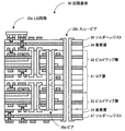
回路基板30は、コア層31を中心として、コア層31の上下にビルドアップ層32,33、最表層34,35が順に形成された鏡面構造が構成されている。さらに、最表層34,35には、ソルダーレジスト36,37が形成されて、回路基板30のショートを防ぎ、絶縁性が保たれて保護されている。
Next, a specific example of a circuit board using the first embodiment will be described below.
FIG. 3 is a schematic cross-sectional view of a circuit board using Example 1 of the present embodiment.
The circuit board 30 has a mirror surface structure in which build-up layers 32 and 33 and
このような回路基板30は以下のような工程によって形成することができる。
まず、コア基板(横×縦×厚さ:510mm×340mm×400μm)として、日立化成製のMCL−E−679FGを用い、回路配線をエッチングにより形成して、その後に2層のコア基板を積層熱プレスして、コア層31を作製した。
Such a circuit board 30 can be formed by the following processes.
First, as a core substrate (horizontal × vertical × thickness: 510 mm × 340 mm × 400 μm), MCL-E-679FG manufactured by Hitachi Chemical Co., Ltd. is used to form circuit wiring by etching, and then two layers of core substrates are stacked. The core layer 31 was produced by hot pressing.
次に、コア層31の上下両側に、2方向に繊維が配向させたプリプレグ(横×縦×厚さ:510mm×340mm×60μm)として日立化成製のGEA−679FGを積層プレスして、2層のビルドアップ層32,33をそれぞれ形成した。その後に、炭酸ガスレーザー加工により開口したブラインドビアホール(IVH:Inner Via Hole)にビアフィルによる銅めっきによりビア38aを形成した。 Next, GEA-679FG manufactured by Hitachi Chemical Co., Ltd. is laminated and pressed as a prepreg (width × length × thickness: 510 mm × 340 mm × 60 μm) in which fibers are oriented in two directions on both upper and lower sides of the core layer 31. Build-up layers 32 and 33 were formed. After that, vias 38a were formed by copper plating with via fill in blind via holes (IVH: Inner Via Hole) opened by carbon dioxide laser processing.
ビルドアップ層32,33を形成した後、さらに、最表層34,35としてGEA−679FGを、ビルドアップ層32,33のGEA−679FGに対して45度回転させて貼り合わせる。最表層34,35を貼り合わせた後、配線およびビア形成加工を行う。
After the buildup layers 32 and 33 are formed, GEA-679FG is further rotated and bonded to the GEA-679FG of the buildup layers 32 and 33 by 45 degrees as the
配線およびビア形成加工後、ソルダーレジスト36,37として太陽インキ製のPSR−4000・AM01NBを塗布して、露光・現像・硬化させた。そして、ソルダーレジスト36,37の所定の位置に開口部を設け、スルーホールをドリル加工により形成し、無電解および電解めっきを施して、スルーホール面にスルービア38bを形成し、ソルダーレジスト36,37の表面のパターンと電気的な接続を形成する。そして、このようにして形成された回路基板30に対して、例えば、LSI回路30aなどを実装し、LSI回路30aに対して電源を供給できる。 After wiring and via formation processing, PSR-4000 / AM01NB made by Taiyo Ink was applied as the solder resist 36, 37, and was exposed, developed and cured. Then, an opening is provided at a predetermined position of the solder resists 36 and 37, a through hole is formed by drilling, electroless and electrolytic plating is performed, a through via 38b is formed on the through hole surface, and the solder resists 36 and 37 are formed. Form electrical connection with the surface pattern. Then, for example, an LSI circuit 30a or the like can be mounted on the circuit board 30 thus formed, and power can be supplied to the LSI circuit 30a.
以上、回路基板30は、コア層31とビルドアップ層32,33とを、配向させた繊維が重なるように積層させて、さらにビルドアップ層32,33の表面に、ビルドアップ層32,33と45度回転させて最表層34,35をそれぞれ形成することで、回路基板30上の実装部品の熱などにより、コア層31およびビルドアップ層32,33と、最表層34,35とに生じた応力を相殺させることができ、回路基板30へのねじれを抑制することができる。また、このような構成は、コア層31およびビルドアップ層32,33はプリプレグを同方向に積層させただけであり、そして、ビルドアップ層32,33に対して45度回転させた最表層34,35をコア層31およびビルドアップ層32,33の表層に形成しただけであるため、現状の製造プロセスをそのまま利用でき、高精度な位置合わせも可能となる。
As described above, the circuit board 30 is formed by laminating the core layer 31 and the buildup layers 32 and 33 so that the oriented fibers overlap with each other, and the buildup layers 32 and 33 are formed on the surfaces of the buildup layers 32 and 33. By rotating 45 degrees and forming the
(実施例2)
実施例2では、1方向に繊維を配向させたプリプレグを利用した場合を例に挙げて説明する。
(Example 2)
In Example 2, a case where a prepreg in which fibers are oriented in one direction is used will be described as an example.
図4は、本実施の形態における実施例2の斜視模式図である。
回路基板40は、コア層41を中心として、コア層41の上下にビルドアップ層42,43、最表層44,45が順に形成された鏡面構造が構成されている。なお、図4では、便宜上、コア層41、ビルドアップ層42,43および最表層44,45を離して示しているが、実際にコア層41、ビルドアップ層42,43および最表層44,45を積層させた回路基板40の断面図は、図2(B)に示したような、コア層41を中心とした鏡面構造が形成される。
FIG. 4 is a schematic perspective view of Example 2 in the present embodiment.
The circuit board 40 has a mirror surface structure in which build-up layers 42 and 43 and
コア層41はプリプレグ47で構成されていて、プリプレグ47は繊維47aに樹脂47bを含浸させて構成させている。このようなコア層41には、所望の回路配線などが形成される。なお、プリプレグ47の繊維47aはプリプレグ47の縦(または横)の辺にそれぞれ平行な1方向に配向させている。また、繊維47aに適用される材料としては、ガラスクロス、アラミドまたは炭素繊維などが考えられる。 The core layer 41 is constituted by a prepreg 47, and the prepreg 47 is constituted by impregnating a fiber 47a with a resin 47b. In such a core layer 41, a desired circuit wiring or the like is formed. The fibers 47 a of the prepreg 47 are oriented in one direction parallel to the vertical (or horizontal) sides of the prepreg 47. Moreover, a glass cloth, an aramid, carbon fiber, etc. can be considered as a material applied to the fiber 47a.
ビルドアップ層42,43は、コア層41の上下にそれぞれ形成されている。また、ビルドアップ層42,43はそれぞれ2層のプリプレグ47で構成されている。なお、プリプレグ47同士の繊維47aがそれぞれ重なるように、コア層41およびビルドアップ層42,43のプリプレグ47を積層している。 The build-up layers 42 and 43 are formed above and below the core layer 41, respectively. Each of the buildup layers 42 and 43 is composed of two prepregs 47. In addition, the prepreg 47 of the core layer 41 and the buildup layers 42 and 43 is laminated so that the fibers 47a of the prepregs 47 overlap each other.
最表層44,45は、ビルドアップ層42,43の外側にそれぞれ形成されている。また、最表層44,45はプリプレグ46で構成されている。なお、プリプレグ46は、プリプレグ47と同様に、繊維46aに樹脂46bを含浸させて構成させており、さらに、プリプレグ46の繊維46aは、コア層41およびビルドアップ層42,43のねじれ方向、すなわち、プリプレグ46の繊維46aを90度回転させた方向に配向させている。
The outermost layers 44 and 45 are formed outside the buildup layers 42 and 43, respectively. Further, the
このように、繊維47aが縦(または横)の辺と平行に配向させたプリプレグ47から構成されるコア層41およびビルドアップ層42,43にて、コア層41の上下にビルドアップ層42,43を形成し、さらに、繊維47aに対して90度回転させた繊維46aを備えたプリプレグ46から構成される最表層44,45をそれぞれ形成することで、回路基板40上の実装部品の熱などにより、コア層41およびビルドアップ層42,43と、最表層44,45とに生じた応力を相殺させることができ、回路基板40へのねじれを抑制することができる。また、このような構成は、コア層41およびビルドアップ層42,43はプリプレグ47を同方向に積層させただけであり、そして、繊維47aに対して90度回転させた繊維46aを備える一対の最表層44,45をコア層41およびビルドアップ層42,43の表層に形成しただけであるため、現状の製造プロセスをそのまま利用でき、高精度な位置合わせも可能となる。
Thus, in the core layer 41 and the build-up layers 42 and 43 that are formed of the prepreg 47 in which the fibers 47a are oriented in parallel with the vertical (or horizontal) sides, the build-up layers 42 and 42 above and below the core layer 41 are provided. 43 and further forming the
(実施例3)
実施例3では、最表層が複数積層したプリプレグから構成される場合を例に挙げて説明する。
(Example 3)
In Example 3, the case where the outermost layer is composed of a prepreg in which a plurality of outermost layers are laminated will be described as an example.
図5は、本実施の形態における実施例3の斜視模式図である。
回路基板50は、コア層51を中心として、コア層51の上下にビルドアップ層52,53、最表層54,55が順に形成された鏡面構造が構成されている。なお、図5では、便宜上、コア層51、ビルドアップ層52,53および最表層54,55を離して示しているが、実際にコア層51、ビルドアップ層52,53および最表層54,55を積層させた回路基板50の断面図は、図2(B)に示したような、コア層51を中心とした鏡面構造が形成される。また、図5に示す実施例3では、実施例1(図2)の2方向に配向させたプリプレグを利用した場合に適用させた例を挙げて説明するが、実施例2(図4)の1方向に配向させたプリプレグを利用した場合にも適用させると、同様の効果を得ることできる。
FIG. 5 is a schematic perspective view of Example 3 in the present embodiment.
The circuit board 50 has a mirror surface structure in which build-up layers 52 and 53 and outermost layers 54 and 55 are sequentially formed on and under the core layer 51 with the core layer 51 as a center. In FIG. 5, for convenience, the core layer 51, the build-up layers 52 and 53, and the outermost layers 54 and 55 are shown apart from each other, but the core layer 51, the build-up layers 52 and 53, and the outermost layers 54 and 55 are actually shown. In the cross-sectional view of the circuit board 50 in which the layers are laminated, a mirror surface structure with the core layer 51 as the center is formed as shown in FIG. In Example 3 shown in FIG. 5, an example applied when the prepreg oriented in two directions of Example 1 (FIG. 2) is used will be described. The same effect can be obtained when applied to the case of using a prepreg oriented in one direction.
コア層51はプリプレグ57で構成されていて、プリプレグ57は繊維57aに樹脂57bを含浸させて構成させている。このようなコア層51には、所望の回路配線などが形成される。なお、プリプレグ57の繊維57aはプリプレグ57の縦および横の各辺にそれぞれ平行な2方向に配向させている。また、繊維57aに適用される材料としては、ガラスクロス、アラミドまたは炭素繊維などが考えられる。 The core layer 51 is constituted by a prepreg 57, and the prepreg 57 is constituted by impregnating a fiber 57a with a resin 57b. Desired circuit wiring or the like is formed on the core layer 51. The fibers 57a of the prepreg 57 are oriented in two directions parallel to the vertical and horizontal sides of the prepreg 57, respectively. Moreover, as a material applied to the fiber 57a, glass cloth, aramid, carbon fiber, or the like can be considered.
ビルドアップ層52,53は、コア層51の上下にそれぞれ形成されている。また、ビルドアップ層52,53はそれぞれ2層のプリプレグ57で構成されている。なお、プリプレグ57同士の繊維57aがそれぞれ重なるように、コア層51およびビルドアップ層52,53のプリプレグ57を積層している。 The build-up layers 52 and 53 are formed above and below the core layer 51, respectively. The buildup layers 52 and 53 are each composed of two prepregs 57. The core layer 51 and the prepregs 57 of the buildup layers 52 and 53 are laminated so that the fibers 57a of the prepregs 57 overlap each other.
最表層54,55は、ビルドアップ層52,53の外側にそれぞれ形成されている。また、最表層54,55は、実施例1,2と異なり、2層のプリプレグ56で構成されている。なお、プリプレグ56は、プリプレグ57と同様に、繊維56aに樹脂56bを含浸させて構成させており、さらに、プリプレグ56の繊維56aは、コア層51およびビルドアップ層52,53のねじれ方向、すなわち、プリプレグ57の繊維57aを45度回転させた方向に配向させている。また、最表層54,55は、プリプレグ56同士の繊維56aが重なるように、それぞれ積層している。 The outermost layers 54 and 55 are formed outside the buildup layers 52 and 53, respectively. Further, unlike the first and second embodiments, the outermost layers 54 and 55 are constituted by two layers of prepregs 56. The prepreg 56 is configured by impregnating the fibers 56a with the resin 56b, similarly to the prepreg 57, and the fibers 56a of the prepreg 56 are twisted in the core layer 51 and the build-up layers 52 and 53, that is, The fibers 57a of the prepreg 57 are oriented in a direction rotated by 45 degrees. Further, the outermost layers 54 and 55 are laminated so that the fibers 56a of the prepregs 56 overlap each other.
このように、繊維57aが各辺と平行に配向させたプリプレグ57から構成されるコア層51およびビルドアップ層52,53にて、コア層51の上下にビルドアップ層52,53を形成し、さらに、繊維57aに対して45度回転させた繊維56aを備えた複数のプリプレグ56から構成される最表層54,55をそれぞれ形成することで、実施例1および実施例2と同様に、回路基板50上の実装部品の熱などにより、コア層51およびビルドアップ層52,53と、最表層54,55とに生じた応力を相殺させることができ、回路基板50へのねじれを抑制することができる。さらに、実施例3では最表層54,55を複数のプリプレグ56から構成させているために、最表層54,55の繊維56aの配向方向への応力に対する強度が大きくなる。このため、コア層51およびビルドアップ層52,53に大きな応力が生じる場合、最表層54,55のプリプレグ56の積層数を増加させることで、互いの応力を相殺させることができる。また、このような構成は、コア層51およびビルドアップ層52,53はプリプレグ57を同方向に積層させただけであり、そして、繊維57aに対して45度回転させた繊維56aを備える一対の最表層54,55をコア層51およびビルドアップ層52,53の表層に形成しただけであるため、現状の製造プロセスをそのまま利用でき、高精度な位置合わせも可能となる。 In this way, in the core layer 51 and the build-up layers 52 and 53 formed of the prepreg 57 in which the fibers 57a are oriented parallel to the respective sides, the build-up layers 52 and 53 are formed above and below the core layer 51, Further, by forming the outermost layers 54 and 55 composed of a plurality of prepregs 56 each having a fiber 56a rotated 45 degrees with respect to the fiber 57a, the circuit board is formed in the same manner as in the first and second embodiments. The stress generated in the core layer 51, the build-up layers 52 and 53, and the outermost layers 54 and 55 can be offset by the heat of the mounted components on the surface 50, and the twist to the circuit board 50 can be suppressed. it can. Furthermore, in Example 3, since the outermost layers 54 and 55 are composed of a plurality of prepregs 56, the strength against stress in the orientation direction of the fibers 56a of the outermost layers 54 and 55 is increased. For this reason, when big stress arises in the core layer 51 and the buildup layers 52 and 53, mutual stress can be offset by increasing the number of lamination | stacking of the prepreg 56 of the outermost layers 54 and 55. FIG. Further, in such a configuration, the core layer 51 and the build-up layers 52 and 53 are simply formed by laminating the prepreg 57 in the same direction, and a pair of fibers 56a rotated 45 degrees with respect to the fibers 57a. Since the outermost layers 54 and 55 are only formed on the surface layers of the core layer 51 and the buildup layers 52 and 53, the current manufacturing process can be used as it is, and high-precision alignment is also possible.
10 回路基板
11,14 プリプレグ
11a,14a 繊維
11b,14b 樹脂
12 中間層
13 ねじれ方向
DESCRIPTION OF SYMBOLS 10 Circuit board 11, 14 Prepreg 11a, 14a Fiber 11b, 14b Resin 12 Intermediate layer 13 Twist direction
Claims (5)
前記中間層のねじれ方向に配向させた第2の繊維に樹脂を含浸させた第2のプリプレグと、を有し、前記中間層は、前記第2のプリプレグに挟持されていることを特徴とする回路基板。 An intermediate layer in which a plurality of first prepregs impregnated with resin in the first fibers are laminated;
A second prepreg in which a second fiber oriented in the twist direction of the intermediate layer is impregnated with a resin, and the intermediate layer is sandwiched between the second prepregs Circuit board.
Priority Applications (1)
| Application Number | Priority Date | Filing Date | Title |
|---|---|---|---|
| JP2007184071A JP2009021470A (en) | 2007-07-13 | 2007-07-13 | Circuit substrate |
Applications Claiming Priority (1)
| Application Number | Priority Date | Filing Date | Title |
|---|---|---|---|
| JP2007184071A JP2009021470A (en) | 2007-07-13 | 2007-07-13 | Circuit substrate |
Publications (1)
| Publication Number | Publication Date |
|---|---|
| JP2009021470A true JP2009021470A (en) | 2009-01-29 |
Family
ID=40360838
Family Applications (1)
| Application Number | Title | Priority Date | Filing Date |
|---|---|---|---|
| JP2007184071A Pending JP2009021470A (en) | 2007-07-13 | 2007-07-13 | Circuit substrate |
Country Status (1)
| Country | Link |
|---|---|
| JP (1) | JP2009021470A (en) |
Cited By (1)
| Publication number | Priority date | Publication date | Assignee | Title |
|---|---|---|---|---|
| JP2016086143A (en) * | 2014-10-29 | 2016-05-19 | 京セラサーキットソリューションズ株式会社 | Wiring board and manufacturing method of the same |
Citations (5)
| Publication number | Priority date | Publication date | Assignee | Title |
|---|---|---|---|---|
| JPH02206196A (en) * | 1989-01-11 | 1990-08-15 | Trw Inc | Multilarger printed circuit board |
| JPH03138137A (en) * | 1989-10-25 | 1991-06-12 | Hitachi Chem Co Ltd | Manufacture of flame retardant laminated and printed wiring board |
| JPH0664095A (en) * | 1992-08-25 | 1994-03-08 | Shin Kobe Electric Mach Co Ltd | Laminated plate |
| JPH08321679A (en) * | 1995-05-24 | 1996-12-03 | Nec Corp | Multilayer printed wiring board |
| JP2004289114A (en) * | 2003-03-03 | 2004-10-14 | Fujitsu Ltd | Packaging substrate and its manufacturing method |
-
2007
- 2007-07-13 JP JP2007184071A patent/JP2009021470A/en active Pending
Patent Citations (5)
| Publication number | Priority date | Publication date | Assignee | Title |
|---|---|---|---|---|
| JPH02206196A (en) * | 1989-01-11 | 1990-08-15 | Trw Inc | Multilarger printed circuit board |
| JPH03138137A (en) * | 1989-10-25 | 1991-06-12 | Hitachi Chem Co Ltd | Manufacture of flame retardant laminated and printed wiring board |
| JPH0664095A (en) * | 1992-08-25 | 1994-03-08 | Shin Kobe Electric Mach Co Ltd | Laminated plate |
| JPH08321679A (en) * | 1995-05-24 | 1996-12-03 | Nec Corp | Multilayer printed wiring board |
| JP2004289114A (en) * | 2003-03-03 | 2004-10-14 | Fujitsu Ltd | Packaging substrate and its manufacturing method |
Cited By (1)
| Publication number | Priority date | Publication date | Assignee | Title |
|---|---|---|---|---|
| JP2016086143A (en) * | 2014-10-29 | 2016-05-19 | 京セラサーキットソリューションズ株式会社 | Wiring board and manufacturing method of the same |
Similar Documents
| Publication | Publication Date | Title |
|---|---|---|
| JP4689375B2 (en) | Laminated substrate and electronic device having the laminated substrate | |
| WO2010007704A1 (en) | Flex-rigid wiring board and electronic device | |
| WO2010013366A1 (en) | Flex-rigid wiring board and method for manufacturing the same | |
| JP2007149870A (en) | Circuit board and manufacturing method therefor | |
| JP4536010B2 (en) | Double woven glass cloth, and prepreg and printed wiring board substrate using the glass cloth | |
| JP2010034199A (en) | Printed wiring board | |
| JP2017017307A (en) | Printed circuit board and method of manufacturing printed circuit board | |
| US20090098391A1 (en) | Core member and method of producing the same | |
| JP2018018936A (en) | Wiring board | |
| JP4924871B2 (en) | Composite board and wiring board | |
| US20140318834A1 (en) | Wiring board and method for manufacturing the same | |
| KR20100012814A (en) | Buildup printed circuit board | |
| JP4954246B2 (en) | Copper-clad laminate and manufacturing method thereof | |
| US20110030207A1 (en) | Multilayer printed wiring board and manufacturing method thereof | |
| KR20080045824A (en) | Carbon fiber stiffener for printed circuit board | |
| JP2009021470A (en) | Circuit substrate | |
| JP6866229B2 (en) | Rigid flex multi-layer printed wiring board | |
| JP2002208763A (en) | Circuit board and method for manufacturing it | |
| JP4961180B2 (en) | Printed wiring board | |
| WO2015041245A1 (en) | Wiring substrate | |
| JP6256741B2 (en) | Package board for mounting semiconductor elements | |
| JP4276227B2 (en) | Multilayer printed wiring board | |
| JP4892924B2 (en) | Multilayer printed wiring board and manufacturing method thereof | |
| JP5318393B2 (en) | Semiconductor device | |
| JP5100429B2 (en) | Manufacturing method of multilayer printed wiring board |
Legal Events
| Date | Code | Title | Description |
|---|---|---|---|
| A621 | Written request for application examination |
Effective date: 20100416 Free format text: JAPANESE INTERMEDIATE CODE: A621 |
|
| A131 | Notification of reasons for refusal |
Free format text: JAPANESE INTERMEDIATE CODE: A131 Effective date: 20111115 |
|
| A977 | Report on retrieval |
Effective date: 20111117 Free format text: JAPANESE INTERMEDIATE CODE: A971007 |
|
| A521 | Written amendment |
Free format text: JAPANESE INTERMEDIATE CODE: A523 Effective date: 20120104 |
|
| A131 | Notification of reasons for refusal |
Effective date: 20120124 Free format text: JAPANESE INTERMEDIATE CODE: A131 |
|
| A02 | Decision of refusal |
Free format text: JAPANESE INTERMEDIATE CODE: A02 Effective date: 20120522 |