JP2007516876A - Droplet ejection assembly - Google Patents
Droplet ejection assembly Download PDFInfo
- Publication number
- JP2007516876A JP2007516876A JP2006547448A JP2006547448A JP2007516876A JP 2007516876 A JP2007516876 A JP 2007516876A JP 2006547448 A JP2006547448 A JP 2006547448A JP 2006547448 A JP2006547448 A JP 2006547448A JP 2007516876 A JP2007516876 A JP 2007516876A
- Authority
- JP
- Japan
- Prior art keywords
- channel
- nozzle opening
- liquid
- nozzle
- droplet ejector
- Prior art date
- Legal status (The legal status is an assumption and is not a legal conclusion. Google has not performed a legal analysis and makes no representation as to the accuracy of the status listed.)
- Pending
Links
Images


Classifications
-
- B—PERFORMING OPERATIONS; TRANSPORTING
- B41—PRINTING; LINING MACHINES; TYPEWRITERS; STAMPS
- B41J—TYPEWRITERS; SELECTIVE PRINTING MECHANISMS, i.e. MECHANISMS PRINTING OTHERWISE THAN FROM A FORME; CORRECTION OF TYPOGRAPHICAL ERRORS
- B41J2/00—Typewriters or selective printing mechanisms characterised by the printing or marking process for which they are designed
- B41J2/005—Typewriters or selective printing mechanisms characterised by the printing or marking process for which they are designed characterised by bringing liquid or particles selectively into contact with a printing material
- B41J2/01—Ink jet
- B41J2/135—Nozzles
- B41J2/14—Structure thereof only for on-demand ink jet heads
- B41J2/14201—Structure of print heads with piezoelectric elements
-
- B—PERFORMING OPERATIONS; TRANSPORTING
- B41—PRINTING; LINING MACHINES; TYPEWRITERS; STAMPS
- B41J—TYPEWRITERS; SELECTIVE PRINTING MECHANISMS, i.e. MECHANISMS PRINTING OTHERWISE THAN FROM A FORME; CORRECTION OF TYPOGRAPHICAL ERRORS
- B41J2/00—Typewriters or selective printing mechanisms characterised by the printing or marking process for which they are designed
- B41J2/005—Typewriters or selective printing mechanisms characterised by the printing or marking process for which they are designed characterised by bringing liquid or particles selectively into contact with a printing material
- B41J2/01—Ink jet
- B41J2/015—Ink jet characterised by the jet generation process
- B41J2/04—Ink jet characterised by the jet generation process generating single droplets or particles on demand
- B41J2/045—Ink jet characterised by the jet generation process generating single droplets or particles on demand by pressure, e.g. electromechanical transducers
-
- B—PERFORMING OPERATIONS; TRANSPORTING
- B41—PRINTING; LINING MACHINES; TYPEWRITERS; STAMPS
- B41J—TYPEWRITERS; SELECTIVE PRINTING MECHANISMS, i.e. MECHANISMS PRINTING OTHERWISE THAN FROM A FORME; CORRECTION OF TYPOGRAPHICAL ERRORS
- B41J2/00—Typewriters or selective printing mechanisms characterised by the printing or marking process for which they are designed
- B41J2/005—Typewriters or selective printing mechanisms characterised by the printing or marking process for which they are designed characterised by bringing liquid or particles selectively into contact with a printing material
- B41J2/01—Ink jet
- B41J2/135—Nozzles
- B41J2/14—Structure thereof only for on-demand ink jet heads
- B41J2/1433—Structure of nozzle plates
-
- B—PERFORMING OPERATIONS; TRANSPORTING
- B41—PRINTING; LINING MACHINES; TYPEWRITERS; STAMPS
- B41J—TYPEWRITERS; SELECTIVE PRINTING MECHANISMS, i.e. MECHANISMS PRINTING OTHERWISE THAN FROM A FORME; CORRECTION OF TYPOGRAPHICAL ERRORS
- B41J2/00—Typewriters or selective printing mechanisms characterised by the printing or marking process for which they are designed
- B41J2/005—Typewriters or selective printing mechanisms characterised by the printing or marking process for which they are designed characterised by bringing liquid or particles selectively into contact with a printing material
- B41J2/01—Ink jet
- B41J2/135—Nozzles
- B41J2/14—Structure thereof only for on-demand ink jet heads
- B41J2002/14475—Structure thereof only for on-demand ink jet heads characterised by nozzle shapes or number of orifices per chamber
Abstract
Description
本発明は液滴の射出に関する。 The present invention relates to droplet ejection.
インクジェットプリンタは基板上に液滴を被着するための装置の一種である。インクジェットプリンタは一般にインク源からノズル路へのインク路を備える。ノズル路は、インク液滴が射出されるノズル開口で終端する。インク液滴射出は一般に、例えば、圧電偏向器、熱バブルジェット(登録商標)発生器または静電偏向素子とすることができる、アクチュエータでインク路にあるインクに圧力を加えることによって制御される。一般的なプリント集成体は対応するノズル開口及び付帯するアクチュエータをもつインク路のアレイを有する。それぞれのノズル開口からの液滴射出は独立に制御することができる。オンデマンド液滴射出プリント集成体においては、プリント集成体及び印刷基板が互いに対して移動させられるとともに、画像の特定の画素位置に液滴を選択的に射出するためにそれぞれのアクチュエータが起動される。高性能プリント集成体において、ノズル開口は一般に50μmないしそれより小さい、例えば約25μmの直径を有し、100〜300ノズル/インチ(3.9〜11.8ノズル/mm)のピッチで隔てられ、100〜3000dpi(3.9〜118.1ドット/mm)ないしそれより高い解像度を有し、約1〜120ピコリットル(pL)ないしそれより少ない体積の液滴を供給する。液滴射出頻度は一般に10kHzないしそれより高い。 An ink jet printer is a type of apparatus for depositing droplets on a substrate. Ink jet printers generally include an ink path from an ink source to a nozzle path. The nozzle path terminates at a nozzle opening through which ink droplets are ejected. Ink droplet ejection is typically controlled by applying pressure to the ink in the ink path with an actuator, which can be, for example, a piezoelectric deflector, a thermal bubble jet generator, or an electrostatic deflection element. A typical print assembly has an array of ink paths with corresponding nozzle openings and associated actuators. Droplet ejection from each nozzle opening can be controlled independently. In an on-demand droplet firing print assembly, the print assembly and the printed circuit board are moved relative to each other and the respective actuators are activated to selectively eject droplets at specific pixel locations in the image. . In high performance print assemblies, the nozzle openings are generally 50 μm or smaller, for example about 25 μm in diameter, separated by a pitch of 100-300 nozzles / inch (3.9-11.8 nozzles / mm); It has a resolution of 100 to 3000 dpi (3.9 to 118.1 dots / mm) or higher and provides droplets with a volume of about 1 to 120 picoliters (pL) or less. The droplet ejection frequency is generally 10 kHz or higher.
ホイジントン(Hoisington)等の特許文献1は半導体の構体及び圧電アクチュエータを有するプリント集成体を説明している。構体はエッチングでインクチャンバが定められたシリコンでつくられる。ノズル開口はシリコンの構体に取り付けられた個別のノズルプレートによって画成される。圧電アクチュエータは、印加電圧に応答して形状寸法を変える、すなわち曲がる、圧電材料層を有する。圧電層の曲がりがインク路に沿って配置されたポンプチャンバ内のインクに圧力を加える。圧電インクジェットプリント集成体は、フィッシュベック(Fishbeck)等の特許文献2,ハイン(Hine)の特許文献3,モイニハン(Moynihan)等の特許文献4及びホイジントンの特許文献5にも説明されており、これらの特許文献の全内容は本明細書に参照として含まれる。
本発明の課題はインクジェットプリンタのプリントヘッドにおいて液滴の射出性能を高める手段を提供することである。 SUMMARY OF THE INVENTION An object of the present invention is to provide a means for enhancing droplet ejection performance in a print head of an ink jet printer.
一態様において、本発明の特徴は、実質的プレーナ基板に形成されたノズル開口から液滴を射出するためにその中で液体に圧力が加えられる流路を備える液滴射出器である。基板にはチャネルもノズル開口の近傍に形成される。チャネルは、ノズル開口幅の約20%ないしそれより大きい距離だけ、ノズル開口から隔てられる。 In one aspect, a feature of the present invention is a droplet ejector that includes a flow path in which pressure is applied to a liquid to eject the droplet from a nozzle opening formed in a substantially planar substrate. A channel is also formed in the substrate in the vicinity of the nozzle opening. The channel is separated from the nozzle opening by a distance of about 20% or more of the nozzle opening width.
別の態様において、本発明の特徴は基板に形成されたノズル開口を通る射出のためにその中で液体に圧力が加えられる流路を備える液滴射出器を提供する工程を含む液体射出の方法である。基板にはチャネルもノズル開口の近傍に形成される。チャネルは、ノズル開口幅の約20%ないしそれより大きい距離だけ、ノズル開口から隔てられる。本方法は、チャネルによって画成される空間に毛管作用力によって吸い込まれる液体を供給する工程及び流路内の液体に圧力を加えることによってノズル開口を通して液体を射出する工程も含む。 In another aspect, a feature of the present invention is a method of liquid ejection comprising providing a droplet ejector comprising a flow path within which pressure is applied to the liquid for ejection through a nozzle opening formed in the substrate. It is. A channel is also formed in the substrate in the vicinity of the nozzle opening. The channel is separated from the nozzle opening by a distance of about 20% or more of the nozzle opening width. The method also includes the step of supplying liquid that is sucked by capillary action force into the space defined by the channel and ejecting the liquid through the nozzle opening by applying pressure to the liquid in the flow path.
その他の態様または実施形態は上記の態様の特徴及び/または以下の1つまたはそれより多くの特徴の組合せを有することができる。ノズル開口はチャネルで囲まれる。チャネルは環形である。チャネルはノズル開口から放射状に延びる。チャネルはノズル開口幅の約2倍ないしそれより小さい幅を有する。チャネルは約100μmないしそれより小さい幅を有する。チャネルは約2μmから約50μmである。基板はシリコン材料である。プレーナ基板は複数のノズル開口及びノズル開口近傍のチャネルを有する。ノズル開口幅は約200μmないしそれより小さい。液滴射出器は圧電アクチュエータを備える。液体は約20〜50ダイン/cm(1ダイン/cm=10−3N/m)の表面張力を有する。液体は約1〜40センチポアズ(1センチポアズ=10−11N・秒/m2)の粘度を有する。 Other aspects or embodiments may have the features of the above aspects and / or combinations of one or more of the following characteristics. The nozzle opening is surrounded by a channel. The channel is annular. The channel extends radially from the nozzle opening. The channel has a width of about twice or less than the nozzle opening width. The channel has a width of about 100 μm or less. The channel is about 2 μm to about 50 μm. The substrate is a silicon material. The planar substrate has a plurality of nozzle openings and channels near the nozzle openings. The nozzle opening width is about 200 μm or less. The droplet ejector includes a piezoelectric actuator. The liquid has a surface tension of about 20-50 dynes / cm (1 dynes / cm = 10 −3 N / m). The liquid has a viscosity of about 1 to 40 centipoise (1 centipoise = 10 −11 N · sec / m 2 ).
実施形態は以下の利点の1つまたはそれより多くを有することができる。液滴形成及び射出との干渉を低減するようにノズルプレートの面の周りの廃インク液が制御されるから、プリントヘッド動作は頑強及び確実である。基板上の精確な場所に小ノズルの大アレイがインクを正確に射出しなければならない高性能プリントヘッドにおいて、液滴の速度及び軌道直線性が維持される。チャネルは廃インク液を制御し、粘度及び表面張力特性が変わるインクのような、様々な液体を噴射する望ましい噴射特性及びノズル開口における圧力特性が変わるヘッドを可能にする。チャネルは頑強であり、可動部品を必要とせず、経済的に、例えばシリコン材料のような半導体材料に、加工、例えばレーザ加工、あるいはエッチングで、実施することができる。 Embodiments can have one or more of the following advantages. Printhead operation is robust and reliable because the waste ink liquid around the surface of the nozzle plate is controlled to reduce interference with drop formation and ejection. In high performance printheads where a large array of small nozzles must eject ink accurately at precise locations on the substrate, drop velocity and trajectory linearity are maintained. The channels control the waste ink liquid and allow the head to change the desired jetting characteristics and various pressure characteristics at the nozzle openings, such as inks that vary in viscosity and surface tension characteristics. The channel is robust, requires no moving parts, and can be implemented economically, for example in semiconductor materials such as silicon materials, by machining, for example laser machining or etching.
さらに別の態様、特徴及び利点は以下に示される。例えば、特定の態様は以下に説明されるチャネル寸法、特性及び動作条件を有する。 Further aspects, features and advantages are set forth below. For example, certain aspects have channel dimensions, characteristics and operating conditions as described below.
図1を参照すれば、インクジェット装置10は、供給インク12を入れている液溜め11及び液溜め11から圧力チャンバ14に通じる液路13を備える。アクチュエータ15,例えば圧電変換器が圧力チャンバ14に重なる。アクチュエータは、インクに力を加えて圧力チャンバ14からノズルプレート18のノズル開口17に通じる液路16を通し、ノズル17から基板20に向けてインク液滴19を射出させるために使用できる。動作中、インクジェット装置10及び基板20は互いに対して移動させることができる。例えば、基板はロール22及び23の間を移動させられる連続ウエブとすることができる。ノズルプレート18のノズル17のアレイからの液滴の選択的射出により、所望の画像が基板20上につくられる。
Referring to FIG. 1, the
インクジェット装置は、システムが液滴を射出していないときのノズル開口近傍のインクメニスカスにおける動作圧力も制御する。メニスカス圧力の変動は、プリントエラー及び滴下を生じさせ得る液滴の体積または速度の変動をおこさせ得る。図示される実施形態において、圧力制御は、液溜め11内のインク12の上方のヘッドスペース9に真空を与える、メカニカルポンプのような真空源30によって与えられる。真空は、重力によってノズル開口17を通るインクの滴下を防止するために、インクを介してノズル開口17に伝えられる。コントローラ32,例えばコンピュータコントローラが、液溜め11のインク上方の真空を監視し、液溜めを所望の真空に維持するために真空源30を調節する。別の実施形態において、インク液溜めをノズル開口の下方に配置してノズル開口近傍に真空を生じさせることによって真空源が与えられる。インクレベルモニタ(図示せず)が、プリント動作中にインクが消費されるとともに低下し、よってノズルにおける真空を高める、インクレベルを検出する。コントローラがインクレベルを監視して、インクが所望のレベルより低下したときに真空を所望の動作範囲内に維持するために、大量容器から液溜めにインクを補充する。メニスカスの真空がノズルの毛管作用力に打ち勝つのに十分に離してノズルの下方に液溜めが配置されている、別の実施形態においては、インクに圧力を加えてノズル開口近傍のメニスカスを維持することができる。実施形態において、真空は約0.5〜約10インチ水柱(1インチ水柱=249Pa)に維持される。
The ink jet device also controls the operating pressure at the ink meniscus near the nozzle opening when the system is not ejecting droplets. Variations in meniscus pressure can cause variations in drop volume or velocity that can cause print errors and drops. In the illustrated embodiment, pressure control is provided by a
図2〜2Aを参照すれば、ノズルプレート部40は実質的プレーナ基板41に形成された複数のノズル開口42を有する。基板41には、それぞれのノズル開口42の近傍にチャネル44の形態のクリーニング構造も形成される。チャネル44は、ノズル性能に影響を与え得るであろう、ノズルプレート上の不要インクを制御する。例えば、インク噴射中、ノズルプレート上にはインクが溜ってしまう。時間が経つにつれてインクはプリントエラーを引き起こす液塊を形成し得る。例えばノズル開口の縁端近傍の液塊は射出される液滴の軌道、速度または体積に影響を与え得る。また、液塊は印刷基板20上に滴下して無意味なマークを生じさせるように十分に大きくもなり得よう。液塊はノズルプレート40の表面から十分遠くに突き出し、印刷基板20に接触して、印刷基板20上に汚れを生じさせることもできよう。チャネル44は廃インク液を集め、局在化して、誘導する。特に図2Aを参照すれば、チャネル44は壇領域43の中心に配置されたそれぞれのノズル開口42を完全に囲む。チャネル44は、チャネル44から出る放射状チャネル46及び48によって連結され、ノズルプレート上の不要液体を誘導及び保持する連結チャネル網を形成する。
Referring to FIGS. 2 to 2A, the
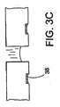
特に図3を参照すれば、液滴射出前のチャネル44が隣接するノズル開口42が示されている。図3A及び3Bを参照すれば、廃インク液38が壇領域43上に溜り、毛管作用力によってチャネル44に引き込まれる。図3Cを参照すれば、廃インク液38はチャネル44に入り、チャネル44によってノズル開口42の周りに広げられる。放射状チャネル46または48に出合うと、インクは放射状チャネルによって画成される空間内に移動し、次いで毛管作用力の下にノズル開口42から放射状に離れる方向に移動して、不要液体を誘導及び保持する連結チャネル網(図2を見よ)に入る。ノズルプレートが垂直方向に配置されている場合、廃インク液は重力及び毛管作用力の両者の影響の下に、巨視的には単一方向に、チャネル網を通って移動する。ノズルプレートが水平方向に配置されている場合、チャネルからインクを除去するために真空源または吸上材料を用いることができる。
With particular reference to FIG. 3, a
チャネルの間隔、寸法及び配置は廃インク液を制御するように選ばれる。実施形態において、チャネルの縁端からノズル開口の縁端までの間隔Sはノズル開口幅WNの約20%ないしそれより大きく、例えば30%ないしそれより大きく、またノズル開口幅の約5倍ないしそれより小さく、例えばノズル開口幅の3倍ないしそれより小さい。チャネルの幅WC及び深さDは、ノズル表面上の過剰なインクの溜りを防止し、チャネルで画成される空間への毛管作用力による液体の引込み及び保持を可能にするように選ばれる。実施形態において、チャネル幅はノズル開口幅の2倍ないしそれより小さく、ノズル開口幅の約10%ないしそれより大きい。特定の実施形態において、チャネル幅WCは、例えば約100μmないしそれより小さく、例えば5〜20μmであり、チャネル深さDは、例えば約2〜10μmないしそれより大きく、例えば50μmである。実施形態において、ノズル開口幅WNは、例えば200μmないしそれより小さく、例えば25〜100μmであり、ノズル開口からチャネルの縁端までの間隔Sは、例えば40μmないしそれより大きく、例えば100μmである。実施形態において、ノズルピッチは約25ノズル/インチ(約0.98ノズル/mm)ないしそれより短く、例えば約300ノズル/インチ(約11.8ノズル/mm)であり、インク液滴体積は約1〜70pLであって、圧電アクチュエータにより液体に圧力が加えられる。実施形態において、噴射液体は約1〜40センチポアズ(1センチポアズ=10−11N・秒/m2)の粘度を有し、約20〜50ダイン/cm(1ダイン/cm=10−3N/m)の表面張力を有する。実施形態において、噴射液体はインクである。実施形態において、チャネルは吸上材料を有することができ、及び/またはノズルとチャネルの間のノズルプレート表面に非湿潤性被覆(例えばテフロン(登録商標)フルオロポリマー)を施すことができる。チャネル網は真空源(図示せず)と通じることもできる。廃インク液は、主インク供給源または個別の吸引システムに戻すことができる。実施形態においてチャネルは環形に配置される。別の実施形態において、チャネルは波形に配置される。 Channel spacing, dimensions, and placement are selected to control the waste ink fluid. In embodiments, the spacing S from the edge of the channel to the edge of the nozzle openings is from about 20% to greater than that of the nozzle opening width W N, for example 30% to greater, also from about 5-fold of the nozzle opening width It is smaller than that, for example, 3 times or less than the nozzle opening width. The channel width W C and depth D are selected to prevent excessive ink accumulation on the nozzle surface and to allow the liquid to be drawn and retained by capillary forces into the space defined by the channel. . In an embodiment, the channel width is twice or less than the nozzle opening width and about 10% or more of the nozzle opening width. In certain embodiments, the channel width W C, for example from about 100μm to less than, for example, 5 to 20 [mu] m, channel depth D, for example about 2~10μm to greater, such as 50 [mu] m. In the embodiment, the nozzle opening width W N is, for example, 200 μm or less, for example, 25 to 100 μm, and the distance S from the nozzle opening to the edge of the channel is, for example, 40 μm or more, for example, 100 μm. In embodiments, the nozzle pitch is about 25 nozzles / inch (about 0.98 nozzles / mm) or less, such as about 300 nozzles / inch (about 11.8 nozzles / mm), and the ink droplet volume is about The pressure is applied to the liquid by the piezoelectric actuator. In an embodiment, the jet liquid has a viscosity of about 1-40 centipoise (1 centipoise = 10 −11 N · sec / m 2 ) and about 20-50 dynes / cm (1 dynes / cm = 10 −3 N / second ). m) surface tension. In an embodiment, the jetting liquid is ink. In embodiments, the channel can have a wicking material and / or a non-wetting coating (eg, Teflon fluoropolymer) can be applied to the nozzle plate surface between the nozzle and the channel. The channel network can also communicate with a vacuum source (not shown). The waste ink liquid can be returned to the main ink supply or a separate suction system. In embodiments, the channels are arranged in a ring shape. In another embodiment, the channels are arranged in a waveform.
上述した実施形態のいずれにおいても、チャネル及び/またはノズル開口は、機械加工、電鋳、レーザアブレーション及び化学エッチングまたはプラズマエッチングで形成することができる。チャネルは成形で形成することもでき、例えば射出成形プラスチックチャネルとすることができる。実施形態において、チャネル、ノズル開口及び圧力チャンバは共通の構体内に形成される。構体は金属、炭素あるいは、シリコン材料、例えばシリコンまたは二酸化ケイ素などの、エッチング可能な材料とすることができる。エッチング法を用いるプリントヘッドコンポーネントの形成は、2002年7月3日に出願された米国特許出願第10/189947号の明細書及び2003年10月10日に出願された米国特許出願第60/510459号の明細書に詳細に説明されており、それぞれの明細書の全内容は本明細書に参照として含まれる。 In any of the embodiments described above, the channels and / or nozzle openings can be formed by machining, electroforming, laser ablation, and chemical or plasma etching. The channel can also be formed by molding, for example an injection molded plastic channel. In an embodiment, the channel, nozzle opening and pressure chamber are formed in a common structure. The structure can be an etchable material such as metal, carbon, or a silicon material such as silicon or silicon dioxide. The formation of printhead components using an etching method is described in US patent application Ser. No. 10/189947, filed Jul. 3, 2002, and US Pat. And the entire contents of each specification are hereby incorporated by reference.
チャネルは、2003年12月30日に出願された米国特許出願第10/749829号の明細書に説明されるアパーチャ、2003年12月30日に出願された米国特許出願第10/749622号の明細書に説明されるウエル及び/または2003年12月30日に出願された米国特許出願第10/749816号の明細書に説明される突起のような、その他の廃液制御態様と組み合わせて用いることができる。例えば、一連の突起をチャネル近傍のノズル面に設けることができる。 Channels are described in US patent application Ser. No. 10/749829 filed on Dec. 30, 2003, US patent application Ser. No. 10 / 769,622 filed Dec. 30, 2003. In combination with other waste control aspects such as wells described in the literature and / or protrusions described in US patent application Ser. No. 10 / 479,816, filed Dec. 30, 2003. it can. For example, a series of protrusions can be provided on the nozzle surface near the channel.
実施形態において、液滴射出システムはインク以外の液体を射出するために利用することができる。例えば、被着される液滴はUV硬化性またはその他の輻射線硬化性の材料、あるいは液滴として送出され得るその他の材料、例えば化学的液体または生物学的液体とすることができる。例えば、説明される装置は、精密計量分配システムの一部とすることができよう。アクチュエータは電気機械アクチュエータまたは熱アクチュエータとすることができる。クリーニング構造を、クリーニング液がノズルプレートに与えられ、拭い取られる、手動または自動の洗浄及び拭取りシステムと組み合わせることができる。クリーニング構造は噴射後の廃インク液ではなくクリーニング液及び屑を集めることができる。 In embodiments, the droplet ejection system can be utilized to eject liquids other than ink. For example, the deposited droplets can be UV curable or other radiation curable materials, or other materials that can be delivered as droplets, such as chemical or biological liquids. For example, the described device could be part of a precision dispensing system. The actuator can be an electromechanical actuator or a thermal actuator. The cleaning structure can be combined with a manual or automatic cleaning and wiping system in which cleaning liquid is applied to the nozzle plate and wiped off. The cleaning structure can collect cleaning liquid and waste, not waste ink liquid after jetting.
その他の実施形態は添付される特許請求の範囲内にある。 Other embodiments are within the scope of the appended claims.
9 ヘッドスペース
10 インクジェット装置
11 液溜め
12 インク
13,16 液路
14 圧力チャンバ
15 アクチュエータ
17 ノズル
18 ノズルプレート
19 インク液滴
20 基板
22,23 ロール
30 真空源
32 コントローラ
44 チャネル
DESCRIPTION OF SYMBOLS 9
Claims (14)
実質的プレーナ基板に形成されたノズル開口から液滴を射出するためにその中で液体に圧力が加えられる流路、及び
前記ノズル開口近傍で前記基板に形成されたチャネルであって、前記開口から前記ノズル開口の幅の約20%ないしそれより大きい距離だけ隔てられているチャンネル、
を備えることを特徴とする液滴射出器。 In droplet ejector,
A flow path in which pressure is applied to the liquid in order to eject droplets from a nozzle opening substantially formed in the planar substrate, and a channel formed in the substrate in the vicinity of the nozzle opening, from the opening Channels separated by a distance of about 20% or more of the width of the nozzle opening;
A droplet ejector comprising:
基板に形成されたノズル開口を通る射出のためにその中で液体に圧力が加えられる流路及び前記基板の前記ノズル開口の近傍に形成されたチャネルを有し、前記チャネルが前記ノズル開口から前記ノズル開口の幅の約20%ないしそれより大きい距離だけ隔てられている、液滴射出器を提供する工程、
前記チャネルで画成される空間に毛管作用力によって吸い込まれる液体を供給する工程、及び
前記流路において前記液体に圧力を加えることによって前記ノズル開口を通して前記液体を射出する工程、
を有してなることを特徴とする方法。 In the method of liquid injection,
A flow path in which pressure is applied to the liquid therein for injection through a nozzle opening formed in the substrate, and a channel formed in the vicinity of the nozzle opening in the substrate, the channel extending from the nozzle opening to the nozzle opening Providing a droplet ejector that is separated by a distance of about 20% or more of the width of the nozzle opening;
Supplying liquid sucked by capillary action force into a space defined by the channel, and ejecting the liquid through the nozzle opening by applying pressure to the liquid in the flow path;
A method comprising the steps of:
Applications Claiming Priority (5)
| Application Number | Priority Date | Filing Date | Title |
|---|---|---|---|
| US10/749,833 US7303259B2 (en) | 2003-12-30 | 2003-12-30 | Drop ejection assembly |
| US10/749,829 US7237875B2 (en) | 2003-12-30 | 2003-12-30 | Drop ejection assembly |
| US10/749,816 US7121646B2 (en) | 2003-12-30 | 2003-12-30 | Drop ejection assembly |
| US10/749,622 US7168788B2 (en) | 2003-12-30 | 2003-12-30 | Drop ejection assembly |
| PCT/US2004/043577 WO2005065294A2 (en) | 2003-12-30 | 2004-12-29 | Drop ejection assembly |
Publications (1)
| Publication Number | Publication Date |
|---|---|
| JP2007516876A true JP2007516876A (en) | 2007-06-28 |
Family
ID=34753903
Family Applications (4)
| Application Number | Title | Priority Date | Filing Date |
|---|---|---|---|
| JP2006547520A Pending JP2007516878A (en) | 2003-12-30 | 2004-12-29 | Droplet ejection assembly |
| JP2006547448A Pending JP2007516876A (en) | 2003-12-30 | 2004-12-29 | Droplet ejection assembly |
| JP2006547572A Pending JP2007516879A (en) | 2003-12-30 | 2004-12-29 | Droplet ejection assembly |
| JP2011094894A Active JP4959013B2 (en) | 2003-12-30 | 2011-04-21 | Droplet ejection assembly |
Family Applications Before (1)
| Application Number | Title | Priority Date | Filing Date |
|---|---|---|---|
| JP2006547520A Pending JP2007516878A (en) | 2003-12-30 | 2004-12-29 | Droplet ejection assembly |
Family Applications After (2)
| Application Number | Title | Priority Date | Filing Date |
|---|---|---|---|
| JP2006547572A Pending JP2007516879A (en) | 2003-12-30 | 2004-12-29 | Droplet ejection assembly |
| JP2011094894A Active JP4959013B2 (en) | 2003-12-30 | 2011-04-21 | Droplet ejection assembly |
Country Status (5)
| Country | Link |
|---|---|
| EP (4) | EP1706269B1 (en) |
| JP (4) | JP2007516878A (en) |
| KR (3) | KR101220272B1 (en) |
| AT (2) | ATE538934T1 (en) |
| WO (3) | WO2005065331A2 (en) |
Cited By (6)
| Publication number | Priority date | Publication date | Assignee | Title |
|---|---|---|---|---|
| JP2012101365A (en) * | 2010-11-05 | 2012-05-31 | Fujifilm Corp | Inkjet head, inkjet recording apparatus, and method for cleaning nozzle plate |
| JP2013043395A (en) * | 2011-08-25 | 2013-03-04 | Canon Inc | Ink-jet recording head |
| WO2015034085A1 (en) * | 2013-09-09 | 2015-03-12 | 武蔵エンジニアリング株式会社 | Nozzle and liquid material discharge device provided with said nozzle |
| US9108425B2 (en) | 2010-11-09 | 2015-08-18 | Canon Kabushiki Kaisha | Recording apparatus and liquid ejection head |
| JP2016172253A (en) * | 2016-05-06 | 2016-09-29 | 武蔵エンジニアリング株式会社 | Liquid material discharge device |
| US10427405B2 (en) | 2017-04-24 | 2019-10-01 | Brother Kogyo Kabushiki Kaisha | Liquid discharging apparatus and ink-jet printer |
Families Citing this family (4)
| Publication number | Priority date | Publication date | Assignee | Title |
|---|---|---|---|---|
| JP4665660B2 (en) * | 2005-08-19 | 2011-04-06 | セイコーエプソン株式会社 | NOZZLE PLATE, MANUFACTURING METHOD THEREOF, AND LIQUID DISCHARGE HEAD |
| US8136934B2 (en) | 2009-02-18 | 2012-03-20 | Xerox Corporation | Waste phase change ink recycling |
| FR2968597A1 (en) * | 2010-12-13 | 2012-06-15 | Centre Nat Rech Scient | INKJET DEVICE HAVING FLUID EXTRACTION MEANS AND INK JET METHOD THEREOF |
| WO2023223196A1 (en) * | 2022-05-16 | 2023-11-23 | Merxin Ltd | Nozzle arrangement |
Citations (3)
| Publication number | Priority date | Publication date | Assignee | Title |
|---|---|---|---|---|
| JPS6219247A (en) * | 1985-07-16 | 1987-01-28 | Toray Ind Inc | Method for eliminating colloidal substance |
| JPH05155028A (en) * | 1991-12-04 | 1993-06-22 | Ricoh Co Ltd | Ink jet head |
| JP2001260361A (en) * | 2000-03-21 | 2001-09-25 | Nec Corp | Nozzle for ink jet recording head and its manufacturing method |
Family Cites Families (37)
| Publication number | Priority date | Publication date | Assignee | Title |
|---|---|---|---|---|
| IT1109303B (en) * | 1978-10-30 | 1985-12-16 | Ipm Ind Politecnica Meridional | UNI-AXIS ANISOTROP MAGNETIZATION CREDIT CARD |
| GB2061831B (en) * | 1979-11-07 | 1984-02-29 | Matsushita Electric Ind Co Ltd | Ink jet writing head with spacer in capillary chamber |
| JPS5763266A (en) * | 1980-10-02 | 1982-04-16 | Seiko Epson Corp | Ink jet head |
| DE3048259A1 (en) * | 1980-12-20 | 1982-07-29 | Philips Patentverwaltung Gmbh, 2000 Hamburg | "NOZZLE FOR INK JET PRINTER" |
| JPS57188372A (en) * | 1981-01-30 | 1982-11-19 | Exxon Research Engineering Co | Ink jet device |
| US4459601A (en) * | 1981-01-30 | 1984-07-10 | Exxon Research And Engineering Co. | Ink jet method and apparatus |
| JPS5995157A (en) * | 1982-11-23 | 1984-06-01 | Yokogawa Hewlett Packard Ltd | Head for bubble driven ink jet printer |
| US4528996A (en) * | 1983-12-22 | 1985-07-16 | The Mead Corporation | Orifice plate cleaning system |
| JPS61115644U (en) * | 1984-12-28 | 1986-07-22 | ||
| US4613875A (en) * | 1985-04-08 | 1986-09-23 | Tektronix, Inc. | Air assisted ink jet head with projecting internal ink drop-forming orifice outlet |
| JPS62150145U (en) * | 1986-03-18 | 1987-09-22 | ||
| US4825227A (en) | 1988-02-29 | 1989-04-25 | Spectra, Inc. | Shear mode transducer for ink jet systems |
| US4992802A (en) * | 1988-12-22 | 1991-02-12 | Hewlett-Packard Company | Method and apparatus for extending the environmental operating range of an ink jet print cartridge |
| US4937598A (en) | 1989-03-06 | 1990-06-26 | Spectra, Inc. | Ink supply system for an ink jet head |
| US5265315A (en) | 1990-11-20 | 1993-11-30 | Spectra, Inc. | Method of making a thin-film transducer ink jet head |
| WO1994008793A1 (en) * | 1992-10-19 | 1994-04-28 | Canon Kabushiki Kaisha | Ink jet head having improved jet port surface, and ink jet apparatus equipped with the ink jet head |
| US5659346A (en) | 1994-03-21 | 1997-08-19 | Spectra, Inc. | Simplified ink jet head |
| US5604521A (en) * | 1994-06-30 | 1997-02-18 | Compaq Computer Corporation | Self-aligning orifice plate for ink jet printheads |
| WO1996002392A1 (en) | 1994-07-20 | 1996-02-01 | Spectra, Inc. | High frequency drop-on-demand ink jet system |
| JPH08230185A (en) * | 1995-03-01 | 1996-09-10 | Brother Ind Ltd | Ink jet device |
| JP3315589B2 (en) * | 1995-06-21 | 2002-08-19 | キヤノン株式会社 | Ink tank and recording apparatus provided with the same |
| JP3386099B2 (en) * | 1995-07-03 | 2003-03-10 | セイコーエプソン株式会社 | Nozzle plate for ink jet recording head, method of manufacturing the same, and ink jet recording head |
| WO1998055317A1 (en) | 1997-06-04 | 1998-12-10 | Seiko Epson Corporation | Ink jet recording head and ink jet recorder |
| US6264307B1 (en) * | 1997-07-15 | 2001-07-24 | Silverbrook Research Pty Ltd | Buckle grill oscillating pressure ink jet printing mechanism |
| US6235212B1 (en) * | 1997-07-15 | 2001-05-22 | Silverbrook Research Pty Ltd | Method of manufacture of an electrostatic ink jet printer |
| US5853861A (en) * | 1997-09-30 | 1998-12-29 | E. I. Du Pont De Nemours And Company | Ink jet printing of textiles |
| US6132028A (en) * | 1998-05-14 | 2000-10-17 | Hewlett-Packard Company | Contoured orifice plate of thermal ink jet print head |
| GB2339170A (en) * | 1998-07-25 | 2000-01-19 | Markem Tech Ltd | Printhead with integral ink gutter |
| US6267464B1 (en) * | 1998-12-28 | 2001-07-31 | Eastman Kodak Company | Self cleaning ink jet printhead cartridges |
| US6283575B1 (en) * | 1999-05-10 | 2001-09-04 | Eastman Kodak Company | Ink printing head with gutter cleaning structure and method of assembling the printer |
| JP2001038917A (en) * | 1999-07-29 | 2001-02-13 | Casio Comput Co Ltd | Ink jet printer |
| JP2001212966A (en) * | 2000-02-04 | 2001-08-07 | Seiko Epson Corp | Hydrophilic structure and ink-jet recording head |
| JP2002187295A (en) * | 2000-12-22 | 2002-07-02 | Hitachi Koki Co Ltd | Ink jet print head and method for sweeping waste ink |
| TW541248B (en) * | 2001-03-16 | 2003-07-11 | Benq Corp | Ink cartridge |
| JP4731763B2 (en) * | 2001-09-12 | 2011-07-27 | キヤノン株式会社 | Liquid jet recording head and manufacturing method thereof |
| US6820963B2 (en) * | 2001-12-13 | 2004-11-23 | Hewlett-Packard Development Company, L.P. | Fluid ejection head |
| US6637862B2 (en) * | 2002-02-08 | 2003-10-28 | Illinois Tool Works, Inc. | Maintenance module for fluid jet device |
-
2004
- 2004-12-29 EP EP04815609A patent/EP1706269B1/en active Active
- 2004-12-29 AT AT04817071T patent/ATE538934T1/en active
- 2004-12-29 KR KR1020067015516A patent/KR101220272B1/en active IP Right Grant
- 2004-12-29 AT AT04815778T patent/ATE538933T1/en active
- 2004-12-29 EP EP04817071A patent/EP1706270B1/en active Active
- 2004-12-29 EP EP11183973A patent/EP2415606A3/en not_active Withdrawn
- 2004-12-29 WO PCT/US2004/043776 patent/WO2005065331A2/en active Application Filing
- 2004-12-29 JP JP2006547520A patent/JP2007516878A/en active Pending
- 2004-12-29 JP JP2006547448A patent/JP2007516876A/en active Pending
- 2004-12-29 EP EP04815778A patent/EP1706266B1/en active Active
- 2004-12-29 WO PCT/US2004/043946 patent/WO2005065378A2/en active Application Filing
- 2004-12-29 KR KR1020067015517A patent/KR101154554B1/en active IP Right Grant
- 2004-12-29 KR KR1020067015519A patent/KR101222582B1/en active IP Right Grant
- 2004-12-29 JP JP2006547572A patent/JP2007516879A/en active Pending
- 2004-12-29 WO PCT/US2004/043577 patent/WO2005065294A2/en active Application Filing
-
2011
- 2011-04-21 JP JP2011094894A patent/JP4959013B2/en active Active
Patent Citations (3)
| Publication number | Priority date | Publication date | Assignee | Title |
|---|---|---|---|---|
| JPS6219247A (en) * | 1985-07-16 | 1987-01-28 | Toray Ind Inc | Method for eliminating colloidal substance |
| JPH05155028A (en) * | 1991-12-04 | 1993-06-22 | Ricoh Co Ltd | Ink jet head |
| JP2001260361A (en) * | 2000-03-21 | 2001-09-25 | Nec Corp | Nozzle for ink jet recording head and its manufacturing method |
Cited By (9)
| Publication number | Priority date | Publication date | Assignee | Title |
|---|---|---|---|---|
| JP2012101365A (en) * | 2010-11-05 | 2012-05-31 | Fujifilm Corp | Inkjet head, inkjet recording apparatus, and method for cleaning nozzle plate |
| US9108425B2 (en) | 2010-11-09 | 2015-08-18 | Canon Kabushiki Kaisha | Recording apparatus and liquid ejection head |
| JP2013043395A (en) * | 2011-08-25 | 2013-03-04 | Canon Inc | Ink-jet recording head |
| WO2015034085A1 (en) * | 2013-09-09 | 2015-03-12 | 武蔵エンジニアリング株式会社 | Nozzle and liquid material discharge device provided with said nozzle |
| JP2015051402A (en) * | 2013-09-09 | 2015-03-19 | 武蔵エンジニアリング株式会社 | Nozzle and liquid material discharge device equipped with nozzle |
| US10010893B2 (en) | 2013-09-09 | 2018-07-03 | Musashi Engineering, Inc. | Nozzle and liquid material discharge device provided with said nozzle |
| US10562045B2 (en) | 2013-09-09 | 2020-02-18 | Musashi Engineering, Inc. | Nozzle and liquid material discharge device provided with said nozzle |
| JP2016172253A (en) * | 2016-05-06 | 2016-09-29 | 武蔵エンジニアリング株式会社 | Liquid material discharge device |
| US10427405B2 (en) | 2017-04-24 | 2019-10-01 | Brother Kogyo Kabushiki Kaisha | Liquid discharging apparatus and ink-jet printer |
Also Published As
| Publication number | Publication date |
|---|---|
| EP2415606A2 (en) | 2012-02-08 |
| KR101220272B1 (en) | 2013-01-09 |
| EP1706266A2 (en) | 2006-10-04 |
| EP1706270A2 (en) | 2006-10-04 |
| EP1706270B1 (en) | 2011-12-28 |
| KR20060127954A (en) | 2006-12-13 |
| ATE538933T1 (en) | 2012-01-15 |
| EP2415606A3 (en) | 2012-05-09 |
| EP1706266A4 (en) | 2009-08-12 |
| ATE538934T1 (en) | 2012-01-15 |
| WO2005065294A2 (en) | 2005-07-21 |
| WO2005065331A2 (en) | 2005-07-21 |
| JP2007516878A (en) | 2007-06-28 |
| JP2007516879A (en) | 2007-06-28 |
| WO2005065378A3 (en) | 2006-02-23 |
| KR101222582B1 (en) | 2013-01-16 |
| JP4959013B2 (en) | 2012-06-20 |
| KR20060127955A (en) | 2006-12-13 |
| WO2005065378A2 (en) | 2005-07-21 |
| KR101154554B1 (en) | 2012-06-14 |
| EP1706269A2 (en) | 2006-10-04 |
| EP1706269B1 (en) | 2012-06-13 |
| JP2011161926A (en) | 2011-08-25 |
| WO2005065331A3 (en) | 2006-12-28 |
| EP1706266B1 (en) | 2011-12-28 |
| WO2005065294A3 (en) | 2005-11-17 |
| EP1706269A4 (en) | 2009-08-19 |
| EP1706270A4 (en) | 2009-08-19 |
| KR20060127957A (en) | 2006-12-13 |
Similar Documents
| Publication | Publication Date | Title |
|---|---|---|
| JP4959013B2 (en) | Droplet ejection assembly | |
| US8287093B2 (en) | Drop ejection assembly | |
| JP5732526B2 (en) | Fluid ejection device | |
| US10118389B2 (en) | Fluid ejection device | |
| US7121646B2 (en) | Drop ejection assembly | |
| US20190134977A1 (en) | Fluid ejection device with a portioning wall | |
| JP2007516879A5 (en) | ||
| US7303259B2 (en) | Drop ejection assembly | |
| JP4936900B2 (en) | Droplet ejection assembly | |
| US7168788B2 (en) | Drop ejection assembly |
Legal Events
| Date | Code | Title | Description |
|---|---|---|---|
| A621 | Written request for application examination |
Free format text: JAPANESE INTERMEDIATE CODE: A621 Effective date: 20071221 |
|
| A977 | Report on retrieval |
Free format text: JAPANESE INTERMEDIATE CODE: A971007 Effective date: 20100514 |
|
| A131 | Notification of reasons for refusal |
Free format text: JAPANESE INTERMEDIATE CODE: A131 Effective date: 20100518 |
|
| A601 | Written request for extension of time |
Free format text: JAPANESE INTERMEDIATE CODE: A601 Effective date: 20100818 |
|
| A602 | Written permission of extension of time |
Free format text: JAPANESE INTERMEDIATE CODE: A602 Effective date: 20100825 |
|
| A601 | Written request for extension of time |
Free format text: JAPANESE INTERMEDIATE CODE: A601 Effective date: 20100921 |
|
| A602 | Written permission of extension of time |
Free format text: JAPANESE INTERMEDIATE CODE: A602 Effective date: 20100929 |
|
| A521 | Request for written amendment filed |
Free format text: JAPANESE INTERMEDIATE CODE: A523 Effective date: 20101018 |
|
| A131 | Notification of reasons for refusal |
Free format text: JAPANESE INTERMEDIATE CODE: A131 Effective date: 20101109 |
|
| A601 | Written request for extension of time |
Free format text: JAPANESE INTERMEDIATE CODE: A601 Effective date: 20110204 |
|
| A602 | Written permission of extension of time |
Free format text: JAPANESE INTERMEDIATE CODE: A602 Effective date: 20110214 |
|
| A521 | Request for written amendment filed |
Free format text: JAPANESE INTERMEDIATE CODE: A523 Effective date: 20110509 |
|
| A02 | Decision of refusal |
Free format text: JAPANESE INTERMEDIATE CODE: A02 Effective date: 20110531 |
|
| A521 | Request for written amendment filed |
Free format text: JAPANESE INTERMEDIATE CODE: A523 Effective date: 20110930 |
|
| A911 | Transfer to examiner for re-examination before appeal (zenchi) |
Free format text: JAPANESE INTERMEDIATE CODE: A911 Effective date: 20111122 |
|
| A912 | Re-examination (zenchi) completed and case transferred to appeal board |
Free format text: JAPANESE INTERMEDIATE CODE: A912 Effective date: 20111216 |
|
| A601 | Written request for extension of time |
Free format text: JAPANESE INTERMEDIATE CODE: A601 Effective date: 20120717 |
|
| A602 | Written permission of extension of time |
Free format text: JAPANESE INTERMEDIATE CODE: A602 Effective date: 20120720 |
|
| A601 | Written request for extension of time |
Free format text: JAPANESE INTERMEDIATE CODE: A601 Effective date: 20120817 |
|
| A602 | Written permission of extension of time |
Free format text: JAPANESE INTERMEDIATE CODE: A602 Effective date: 20120822 |