JP2007516878A - Droplet ejection assembly - Google Patents
Droplet ejection assembly Download PDFInfo
- Publication number
- JP2007516878A JP2007516878A JP2006547520A JP2006547520A JP2007516878A JP 2007516878 A JP2007516878 A JP 2007516878A JP 2006547520 A JP2006547520 A JP 2006547520A JP 2006547520 A JP2006547520 A JP 2006547520A JP 2007516878 A JP2007516878 A JP 2007516878A
- Authority
- JP
- Japan
- Prior art keywords
- nozzle opening
- droplet ejector
- protrusion
- ejector according
- nozzle
- Prior art date
- Legal status (The legal status is an assumption and is not a legal conclusion. Google has not performed a legal analysis and makes no representation as to the accuracy of the status listed.)
- Pending
Links
Images


Classifications
-
- B—PERFORMING OPERATIONS; TRANSPORTING
- B41—PRINTING; LINING MACHINES; TYPEWRITERS; STAMPS
- B41J—TYPEWRITERS; SELECTIVE PRINTING MECHANISMS, i.e. MECHANISMS PRINTING OTHERWISE THAN FROM A FORME; CORRECTION OF TYPOGRAPHICAL ERRORS
- B41J2/00—Typewriters or selective printing mechanisms characterised by the printing or marking process for which they are designed
- B41J2/005—Typewriters or selective printing mechanisms characterised by the printing or marking process for which they are designed characterised by bringing liquid or particles selectively into contact with a printing material
- B41J2/01—Ink jet
- B41J2/135—Nozzles
- B41J2/14—Structure thereof only for on-demand ink jet heads
- B41J2/14201—Structure of print heads with piezoelectric elements
-
- B—PERFORMING OPERATIONS; TRANSPORTING
- B41—PRINTING; LINING MACHINES; TYPEWRITERS; STAMPS
- B41J—TYPEWRITERS; SELECTIVE PRINTING MECHANISMS, i.e. MECHANISMS PRINTING OTHERWISE THAN FROM A FORME; CORRECTION OF TYPOGRAPHICAL ERRORS
- B41J2/00—Typewriters or selective printing mechanisms characterised by the printing or marking process for which they are designed
- B41J2/005—Typewriters or selective printing mechanisms characterised by the printing or marking process for which they are designed characterised by bringing liquid or particles selectively into contact with a printing material
- B41J2/01—Ink jet
- B41J2/135—Nozzles
- B41J2/14—Structure thereof only for on-demand ink jet heads
-
- B—PERFORMING OPERATIONS; TRANSPORTING
- B41—PRINTING; LINING MACHINES; TYPEWRITERS; STAMPS
- B41J—TYPEWRITERS; SELECTIVE PRINTING MECHANISMS, i.e. MECHANISMS PRINTING OTHERWISE THAN FROM A FORME; CORRECTION OF TYPOGRAPHICAL ERRORS
- B41J2/00—Typewriters or selective printing mechanisms characterised by the printing or marking process for which they are designed
- B41J2/005—Typewriters or selective printing mechanisms characterised by the printing or marking process for which they are designed characterised by bringing liquid or particles selectively into contact with a printing material
- B41J2/01—Ink jet
- B41J2/015—Ink jet characterised by the jet generation process
- B41J2/04—Ink jet characterised by the jet generation process generating single droplets or particles on demand
- B41J2/045—Ink jet characterised by the jet generation process generating single droplets or particles on demand by pressure, e.g. electromechanical transducers
-
- B—PERFORMING OPERATIONS; TRANSPORTING
- B41—PRINTING; LINING MACHINES; TYPEWRITERS; STAMPS
- B41J—TYPEWRITERS; SELECTIVE PRINTING MECHANISMS, i.e. MECHANISMS PRINTING OTHERWISE THAN FROM A FORME; CORRECTION OF TYPOGRAPHICAL ERRORS
- B41J2/00—Typewriters or selective printing mechanisms characterised by the printing or marking process for which they are designed
- B41J2/005—Typewriters or selective printing mechanisms characterised by the printing or marking process for which they are designed characterised by bringing liquid or particles selectively into contact with a printing material
- B41J2/01—Ink jet
- B41J2/135—Nozzles
- B41J2/14—Structure thereof only for on-demand ink jet heads
- B41J2/1433—Structure of nozzle plates
-
- B—PERFORMING OPERATIONS; TRANSPORTING
- B41—PRINTING; LINING MACHINES; TYPEWRITERS; STAMPS
- B41J—TYPEWRITERS; SELECTIVE PRINTING MECHANISMS, i.e. MECHANISMS PRINTING OTHERWISE THAN FROM A FORME; CORRECTION OF TYPOGRAPHICAL ERRORS
- B41J2/00—Typewriters or selective printing mechanisms characterised by the printing or marking process for which they are designed
- B41J2/005—Typewriters or selective printing mechanisms characterised by the printing or marking process for which they are designed characterised by bringing liquid or particles selectively into contact with a printing material
- B41J2/01—Ink jet
- B41J2/135—Nozzles
- B41J2/14—Structure thereof only for on-demand ink jet heads
- B41J2002/14475—Structure thereof only for on-demand ink jet heads characterised by nozzle shapes or number of orifices per chamber
Abstract
Description
本発明は基板上への液滴の被着に関する。 The present invention relates to the deposition of droplets on a substrate.
インクジェットプリンタは基板上に液滴を被着するための装置の一種である。インクジェットプリンタは一般にインク源からノズル路へのインク路を備える。ノズル路は、インク液滴が射出されるノズル開口で終端する。インク液滴射出は一般に、例えば、圧電偏向器、熱バブルジェット(登録商標)発生器または静電偏向素子とすることができる、アクチュエータでインク路にあるインクに圧力を加えることによって制御される。一般的なプリント集成体は対応するノズル開口及び付帯するアクチュエータをもつインク路のアレイを有する。それぞれのノズル開口からの液滴射出は独立に制御することができる。オンデマンド液滴射出プリント集成体においては、プリント集成体及び印刷基板が互いに対して移動するとともに画像の特定の画素位置に液滴を選択的に射出するためにそれぞれのアクチュエータが起動される。高性能プリント集成体において、ノズル開口は一般に50μmないしそれより小さい、例えば約25μmの直径を有し、100〜300ノズル/インチ(3.9〜11.8ノズル/mm)のピッチで隔てられ、100〜3000dpi(3.9〜118.1ドット/mm)ないしそれより高い解像度を有し、約1〜120ピコリットル(pL)ないしそれより少ない体積の液滴を供給する。液滴射出頻度は一般に10kHzないしそれより高い。 An ink jet printer is a type of apparatus for depositing droplets on a substrate. Ink jet printers generally include an ink path from an ink source to a nozzle path. The nozzle path terminates at a nozzle opening through which ink droplets are ejected. Ink droplet ejection is typically controlled by applying pressure to the ink in the ink path with an actuator, which can be, for example, a piezoelectric deflector, a thermal bubble jet generator, or an electrostatic deflection element. A typical print assembly has an array of ink paths with corresponding nozzle openings and associated actuators. Droplet ejection from each nozzle opening can be controlled independently. In an on-demand droplet ejection print assembly, the actuator is activated to selectively eject droplets to specific pixel locations in the image as the print assembly and print substrate move relative to each other. In high performance print assemblies, the nozzle openings are generally 50 μm or smaller, for example about 25 μm in diameter, separated by a pitch of 100-300 nozzles / inch (3.9-11.8 nozzles / mm); It has a resolution of 100 to 3000 dpi (3.9 to 118.1 dots / mm) or higher and provides droplets with a volume of about 1 to 120 picoliters (pL) or less. The droplet ejection frequency is generally 10 kHz or higher.
ホイジングトン(Hoisington)等の特許文献1は半導体の構体及び圧電アクチュエータを有するプリント集成体を説明している。構体はエッチングでインクチャンバが画成されたシリコンでつくられる。ノズル開口はシリコンの構体に取り付けられた個別のノズルプレートによって画成される。圧電アクチュエータは、印加電圧に応答して形状寸法を変える、すなわち曲がる、圧電材料層を有する。圧電層の曲がりがインク路に沿って配置されたポンプチャンバ内のインクに圧力を加える。圧電インクジェットプリント集成体は、フィッシュベック(Fishbeck)等の特許文献2,ハイン(Hine)の特許文献3,モイニハン(Moynihan)等の特許文献4及びホイジングトンの特許文献5にも説明されており、これらの特許文献の全内容は本明細書に参照として含まれる。
本発明の課題はインクジェットプリンタのプリントヘッドにおいて液滴の射出性能を高める手段を提供することである。 SUMMARY OF THE INVENTION An object of the present invention is to provide a means for enhancing droplet ejection performance in a print head of an ink jet printer.
一態様において、本発明の特徴はノズル開口から液滴を射出するためにその中で液体に圧力が加えられる流路を備える液滴射出器である。ノズル開口に隣接して、ノズル開口の平面に交わる方向に延びる複数の突起がある。 In one aspect, a feature of the present invention is a droplet ejector comprising a flow path in which pressure is applied to the liquid to eject the droplet from the nozzle opening. Adjacent to the nozzle opening, there are a plurality of protrusions extending in a direction intersecting the plane of the nozzle opening.
別の態様において、本発明の特徴はノズル開口を通る射出のためにその中で液体に圧力が加えられる流路を備える液滴射出器である。ノズル開口近傍に、ノズル開口の平面に交わる方向に延びる少なくとも4本の立柱がある。立柱及びノズル開口は共通の構体内に画成される。 In another aspect, a feature of the present invention is a droplet ejector comprising a flow path within which pressure is applied to the liquid for ejection through the nozzle opening. In the vicinity of the nozzle opening, there are at least four standing pillars extending in a direction intersecting the plane of the nozzle opening. The upright and nozzle openings are defined in a common structure.
別の態様において、本発明の特徴はノズル開口を通る射出のためにその中で液体に圧力が加えられる流路を備えるプリントヘッドを提供することによる液体射出である。ノズル開口近傍に、ノズル開口の平面に交わる方向に延びる複数の突起がある。突起で画成される空間に毛管作用力によって吸い込まれる液体が供給される。 In another aspect, a feature of the present invention is liquid ejection by providing a printhead with a flow path in which pressure is applied to the liquid for ejection through a nozzle opening. In the vicinity of the nozzle opening, there are a plurality of protrusions extending in the direction intersecting the plane of the nozzle opening. The liquid sucked by the capillary action force is supplied to the space defined by the protrusions.
別の態様において、本発明の特徴はノズル開口から液滴を射出するためにその中で液体に圧力が加えられる流路を備える液滴射出器である。ノズル開口に隣接して、ノズル開口の平面に交わる方向に延びる複数の突起がある。ノズル開口及び突起はシリコン材料でつくられた共通の構体内に画成され、ノズル開口は壇上に配置され、突起は壇の近傍に配置される。 In another aspect, a feature of the present invention is a droplet ejector comprising a flow path in which pressure is applied to the liquid to eject the droplet from the nozzle opening. Adjacent to the nozzle opening, there are a plurality of protrusions extending in a direction intersecting the plane of the nozzle opening. The nozzle openings and projections are defined in a common structure made of silicon material, the nozzle openings are arranged on the platform, and the projections are arranged in the vicinity of the platform.
その他の態様または実施形態は上記の態様の特徴及び以下の1つまたはそれより多くの特徴の組合せを有することができる。ノズル開口は突起で囲まれる。突起は立柱であるかまたは壁体形である。突起はパターンに配列される。パターンは行列アレイを画成し、あるいは円弧を画成する。パターンはインク溜り空間を画成する。突起はノズル開口幅の約2倍ないしそれより小さい幅を有する。突起とノズル開口の周縁との間隔はノズル開口幅の約20%ないしそれより大きい。突起の間隔はノズル開口幅の約2倍ないしそれより小さい。突起の数は4個ないしそれより多い。突起の高さはノズル開口の平面に実質的に等しいか、あるいは突起の高さはノズル開口の平面より低い。 Other aspects or embodiments may have the features of the aspects described above and combinations of one or more of the following features. The nozzle opening is surrounded by a protrusion. The protrusions are upright or wall-shaped. The protrusions are arranged in a pattern. The pattern defines a matrix array or arc. The pattern defines an ink reservoir space. The protrusion has a width of about twice or less than the nozzle opening width. The distance between the protrusion and the periphery of the nozzle opening is about 20% or more of the nozzle opening width. The distance between the protrusions is about twice or less than the nozzle opening width. The number of protrusions is 4 or more. The height of the protrusion is substantially equal to the plane of the nozzle opening, or the height of the protrusion is lower than the plane of the nozzle opening.
ノズル開口及び突起は共通の構体内に画成され、構体はシリコン材料である。液滴射出器は突起近傍にチャネルを備える。液滴射出器は突起近傍に真空源または吸上材料を備える。ノズル開口はウエル内に配置され、ウエルは突起を有する。ノズル開口は壇上に配置され、突起は壇近傍に配置される。ノズル開口は200μmないしそれより小さい。液滴射出器は圧電アクチュエータを備える。 The nozzle opening and the protrusion are defined in a common structure, and the structure is a silicon material. The droplet ejector includes a channel near the protrusion. The droplet ejector includes a vacuum source or a wicking material in the vicinity of the protrusion. The nozzle opening is disposed in the well, and the well has a protrusion. The nozzle opening is disposed on the platform, and the protrusion is disposed in the vicinity of the platform. The nozzle opening is 200 μm or smaller. The droplet ejector includes a piezoelectric actuator.
実施形態は以下の利点の1つまたはそれより多くを有することができる。液滴形成及び射出との干渉を低減するようにノズルプレートの面の周りの廃インク液が制御されるから、プリントヘッド動作は頑強及び確実である。基板上の精確な場所に小ノズルの大アレイがインクを正確に射出しなければならない高性能プリントヘッドにおいて、液滴の速度及び軌道直線性が維持される。突起は廃インク液を制御し、粘度及び表面張力特性が変わるインクのような、様々な液体を噴射する望ましい噴射特性及びノズル開口における圧力特性が変わるヘッドを可能にする。突起は頑強であり、可動部品を必要とせず、経済的に、例えばシリコン材料のような半導体材料に、エッチングで実施することができる。 Embodiments can have one or more of the following advantages. Printhead operation is robust and reliable because the waste ink liquid around the surface of the nozzle plate is controlled to reduce interference with drop formation and ejection. In high performance printheads where a large array of small nozzles must eject ink accurately at precise locations on the substrate, drop velocity and trajectory linearity are maintained. The protrusions control the waste ink liquid and allow the head to vary the desired ejection characteristics and various pressure characteristics at the nozzle openings, such as inks that vary in viscosity and surface tension characteristics. The protrusions are robust, do not require moving parts, and can be economically implemented by etching into a semiconductor material such as a silicon material.
さらに別の態様、特徴及び利点は以下に示される。例えば、特定の態様は以下に論じられるような突起寸法、特性及び動作条件を有する。 Further aspects, features and advantages are set forth below. For example, certain aspects have protrusion dimensions, characteristics and operating conditions as discussed below.
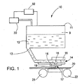
図1を参照すれば、インクジェット装置10は、供給インク12を入れている液溜め11及び液溜め11から圧力チャンバ14に通じる液路13を備える。アクチュエータ15,例えば圧電変換器が圧力チャンバ14の壁の1つを形成する。アクチュエータは、インクに力を加えて圧力チャンバ14からノズルプレート18のノズル開口17に通じる液路16を通し、ノズル17から基板20に向けてインク液滴19を射出させるために使用できる。動作中、インクジェット装置10及び基板20は互いに対して移動させることができる。例えば、基板はロール22及び23の間を移動させられる連続ウエブとすることができる。ノズルプレート18のノズル17のアレイからの液滴の選択的射出により、所望の画像が基板20上につくられる。
Referring to FIG. 1, the
インクジェット装置は、システムが液滴を射出していないときのノズル開口近傍のインクメニスカスにおける動作圧力も制御する。メニスカス圧力の変動は、プリントエラー及び滴下を生じさせ得る液滴の体積または速度の変動をおこさせ得る。図示される実施形態において、圧力制御は、液溜め11内のインク12の上方のヘッドスペース9に真空を与える、メカニカルポンプのような真空源30によって与えられる。真空は、重力によってノズル開口17を通るインクの滴下を防止するために、インクを介してノズル開口17に伝えられる。コントローラ32,例えばコンピュータコントローラが、液溜め11のインク上方の真空を監視し、液溜めを所望の真空に維持するために真空源30を調節する。別の実施形態において、真空源はインク液溜めをノズル開口の下に配置してノズル開口近傍に真空を生じさせることによって与えられる。インクレベルモニタ(図示せず)が、プリント動作中にインクが消費されるとともに低下し、よってノズルにおける真空を高める、インクレベルを検出する。コントローラがインクレベルを監視し、インクが所望のレベルより低下したときに真空を所望の動作範囲内に維持するために、大量容器から液溜めにインクを補充する。メニスカスの真空がノズルの毛管作用力に打ち勝つのに十分に離してノズルの下方に液溜めが配置されている、別の実施形態においては、インクに圧力を加えてノズル開口近傍のメニスカスを維持することができる。実施形態において、動作真空は約0.5〜約10インチ水柱(1インチ水柱=249Pa)に維持される。
The ink jet device also controls the operating pressure at the ink meniscus near the nozzle opening when the system is not ejecting droplets. Variations in meniscus pressure can cause variations in drop volume or velocity that can cause print errors and drops. In the illustrated embodiment, pressure control is provided by a
図2を参照すれば、ノズルプレート部90は、高壇92及び壇92の中心に配置されたノズル開口94を有する。壇92及びノズル開口94の近傍に、ノズル開口94の平面に交わる方向にノズルプレートの床面から延びる円柱の形態のインク制御突起96の領域がある。インク噴射中、ノズルプレート18上にインクが溜り得る。インク溜りが制御されていなければ、時間がたつにつれて、インクはプリントエラーを生じさせる液塊を形成し得る。例えば、ノズル開口の縁端近傍の液塊は、射出される液滴の軌道、速度または体積に影響を与え得る。また、液塊は印刷基板上に滴下して無意味なマークを生じさせるような十分な大きさになることができよう。液塊はノズルプレート面から十分遠くに突き出し、印刷基板に接触して、印刷基板に汚れを生じさせることもできるであろう。突起96は廃液をノズルプレートの周りに広げ、よって、例えばノズルプレートから印刷基板上に滴下し得る、厚い液塊の成長を抑える。初め、液塊は壇92上に形成され、次いで、壇92から壇92の近傍の突起96の領域に移動する。突起96は、毛管作用力によって廃液がノズル開口94から離れる方向に吸い取られるような空間98を画成する。
Referring to FIG. 2, the
図3を参照すれば、ノズルプレートの2つの領域90,90'は図示されるように2つの隣接ノズル開口94,94'を有する。領域90,90'のそれぞれはノズル開口を囲む突起の領域を有する。突起領域は空白領域114,115及び117,及び廃液チャネル119,112によって境界が画成される。チャネル119,122はドレインアパーチャ121を有する。突起のパターンはインクをノズルから離してチャネルに向ける。ノズルプレートが水平方向に配置されている(ノズル開口が上方または下方を向く)場合、廃インク液塊は初め毛管作用の影響の下で突起−突起間から、4つの概略方向112,116,118及び120を含む、可能なあらゆる方向に移動する。廃インク液が空白領域114,115または117に達すると、毛管作用力が廃インク液をそれまでと同じ方向に移動させ続けるには突起96の間隔が大きすぎるから、廃インク液の同じ方向への移動は阻止される。廃インク液の移動はチャネル119,122に出合うまで続き、チャネル119,122が廃インク液を受け止める。実施形態において、アパーチャ121は、廃インクをそれぞれのチャネルから引き出すため、例えばメカニカル真空装置(図示せず)と通じていることで、減圧下に維持される。あるいは、アパーチャには、それぞれのチャネル119から廃インク液を除去するために吸上材料、例えば、発泡ウレタンまたはその他の吸収材料を充填することができる。実施形態において、突起幅に対する突起高の比は、約0.2から約1ないしそれより大きく、例えば約5ないしそれより大きい。ノズルプレートが垂直方向に配置されている場合、廃インク液は重力及び毛管作用力の影響の下で突起−突起間から、ノズルプレート110の配置方向に依存して、巨視的には単一方向112,116,118または120に、移動する。適するチャネルは2003年12月30日に出願された米国特許出願第10/749833号の明細書に説明され、適するアパーチャは2003年12月30日に出願された米国特許出願第10/749829号の明細書に説明されており、これらの明細書の全開示は本明細書に参照として含まれる。
Referring to FIG. 3, the two
突起の間隔、寸法、位置、形状、数及びパターンは、ノズル開口周りの領域におけるノズルプレートの表面積を大きくすることによってノズル表面上のインクの過剰な溜りを防止するように選ばれる。突起の間隔Gの寸法は、毛管作用力によって液体が突起間空間に引き込まれて保持されるであろうような寸法である。実施形態において、間隔Gはノズル開口幅WNの約20%ないしそれより大きい値とノズル開口幅WNの約2倍ないしそれより小さい値の間である。実施形態において、突起のパターンは複数組の行及び列を画成する。実施形態において、パターンは円弧を画成する。突起のパターンは廃インク液をノズルプレート上の所望の方向に誘導するように配置することができる。 The spacing, size, position, shape, number and pattern of protrusions are selected to prevent excessive accumulation of ink on the nozzle surface by increasing the surface area of the nozzle plate in the area around the nozzle opening. The dimension of the gap G between the protrusions is such a dimension that the liquid will be drawn and held in the interprotrusion space by the capillary action force. In embodiments, the gap G is between about 2-fold to it a value less than about 20% to value greater than a nozzle opening width W N of the nozzle opening width W N. In embodiments, the pattern of protrusions defines multiple sets of rows and columns. In an embodiment, the pattern defines an arc. The pattern of protrusions can be arranged to guide the waste ink liquid in a desired direction on the nozzle plate.
突起の幅WPは、表面積のかなりの増大を与えるのに十分に小さいが、実質的に頑強であるのに十分に大きい。さらに、突起の幅は上面に過剰な廃インク液が溜るほど大きくはない。実施形態において、突起の幅はノズル開口幅の約2倍ないしそれより小さい。突起の高さHPはノズル開口の平面より高いか、平面に等しいかあるいは平面より低い。突起が長くなるほど、得られる表面積が大きくなるから、保持できる廃インク液の量が多くなる。ノズル開口平面より低い突起は損傷を受け難い。ノズル開口平面に等しい突起は、いくつかの場合において、例えばエッチングによる作成がより容易である。 Width W P of the protrusions is sufficiently small to give a significant increase in surface area is large enough to be substantially robust. Further, the width of the protrusion is not so large that excessive waste ink liquid is accumulated on the upper surface. In an embodiment, the width of the protrusion is about twice or less than the nozzle opening width. The height H P of the protrusions is higher than the plane of the nozzle opening, is lower than or equal to the plane. The longer the protrusions, the larger the surface area obtained, so the amount of waste ink liquid that can be retained increases. Protrusions below the nozzle opening plane are less susceptible to damage. Protrusions equal to the nozzle opening plane are easier to create in some cases, for example by etching.
突起はノズルプレート上の廃インク液が溜り得る場所に配置される。実施形態において、突起はノズル開口を実質的に囲む。実施形態において、突起は、液滴射出に影響を与え得るノズル開口に近すぎる場所での廃インク液の溜りを抑えるために、ノズル開口から隔てられる。実施形態において、ノズル開口幅WNの約20%ないし200%よりノズル開口の周縁に突起が近づくことはない。 The protrusions are arranged at locations where the waste ink liquid on the nozzle plate can accumulate. In an embodiment, the protrusion substantially surrounds the nozzle opening. In an embodiment, the protrusions are spaced from the nozzle openings to suppress waste ink liquid accumulation in locations too close to the nozzle openings that can affect droplet ejection. In embodiments, the projections on the periphery of the nozzle opening will not be closer than about 20% to 200% of the nozzle opening width W N.
実施形態において、突起の形状は細長い立柱である。立柱は、例えば断面が円形であるかまたは断面が不規則であり得る。立柱は、ノズル開口の平面に実質的に垂直であるかまたは直角とは別の角度をなしてノズル開口平面に交わり得る。別の実施形態において、突起は壁体構造である。壁体構造はかなりの面積を覆ってノズルプレートに付けることができ、よって、レジストを除去してノズルプレートを別の構体、例えば基板に接触させるべきである。 In the embodiment, the shape of the protrusion is an elongated vertical pillar. The uprights can be, for example, circular in cross section or irregular in cross section. The uprights can be substantially perpendicular to the plane of the nozzle opening or meet the nozzle opening plane at an angle other than a right angle. In another embodiment, the protrusion is a wall structure. The wall structure can cover a substantial area and be applied to the nozzle plate, so the resist should be removed to bring the nozzle plate into contact with another structure, such as the substrate.
立柱の数は、上で論じたように、所望の噴射液体体積を制御するかまたは所望のパターンをつくるように選ばれる。突起がノズル開口を囲む実施形態においては、4個ないしそれより多くの、例えば6個ないしそれより多くの立柱がある。 The number of uprights is selected to control the desired jet liquid volume or create the desired pattern, as discussed above. In embodiments where the protrusion surrounds the nozzle opening, there are 4 or more, for example 6 or more uprights.
特定の実施形態において、突起の高さHPは例えば約5μmから約100μmないしそれより大きく、例えば200μmである。最近接立柱から壇の縁端までの間隔Sは例えば約10μmから約20μmであり、突起間の隙間Gは例えば約5μmから約25μmである。突起の幅WPは例えば約5μmから約20μmである。実施形態において、ノズル開口幅は約200μmないしそれより小さく、例えば10〜50μmであり、ノズルピッチは約25ノズル/インチ(約0.98ノズル/mm)ないしそれより短く、例えば約100〜300ノズル/インチ(約3.9〜11.8ノズル/mm)であり、インク液滴体積は約1〜70pLであって、圧電アクチュエータによって液体に圧力が加えられる。実施形態において、噴射液体は約20〜50ダイン/cm(1ダイン/cm=10−3N/m)の表面張力を有する。実施形態において、噴射液体はインクである。実施形態において、噴射液体は生物学的液体である。 In certain embodiments, the height H P of the protrusions is greater than about 100μm to from example about 5 [mu] m, for example, 200 [mu] m. The distance S from the closest column to the edge of the platform is, for example, about 10 μm to about 20 μm, and the gap G between the protrusions is, for example, about 5 μm to about 25 μm. Width W P of the projections is about 20μm, for example, from about 5 [mu] m. In an embodiment, the nozzle opening width is about 200 μm or less, for example 10 to 50 μm, and the nozzle pitch is about 25 nozzles / inch (about 0.98 nozzles / mm) or less, for example about 100 to 300 nozzles. / Inch (about 3.9 to 11.8 nozzles / mm), the ink droplet volume is about 1 to 70 pL, and pressure is applied to the liquid by the piezoelectric actuator. In embodiments, the jet liquid has a surface tension of about 20-50 dynes / cm (1 dynes / cm = 10 −3 N / m). In an embodiment, the jetting liquid is ink. In embodiments, the jet liquid is a biological liquid.
次に図4を参照すれば、ノズルプレート領域120はウエル124内に配置されたノズル開口126を有し、ノズル開口126はノズル開口126近傍の円柱の形態の突起125によって囲まれている。突起125はウエル内に廃インク液を対称に広げる。時間が経つにつれて、ウエル124は噴射液体である程度満たされて、ノズル開口を覆うメニスカスが形成される。液体の噴射を容易にするためのウエルの使用は、本明細書と同時に出願され、譲渡された、2003年12月30日に出願され、名称を「液滴射出集成体(DROP EJECTION ASSEMBLY)」とする、米国特許出願第10/749622号の明細書に説明されており、この明細書の開示はその全体が本明細書に参照として含まれる。
Referring now to FIG. 4, the
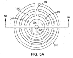
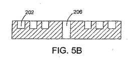
図5〜5Bを参照すれば、ノズルプレート領域200は、高壇204の周りに断続的な同心表面を形成する壁体の形態の複数の円弧突起202及び壇204の中心に配置されたノズル開口206を有する。高壇204の周りの突起202は、ノズル開口202の平面に交わる方向に延びる。高壇204の縁端203と高壇204の周りの第1の断続する同心表面を形成する第1の円弧突起202の列の間に第1の空間207が形成される。ノズル開口206の中心から径方向に等距離にある突起202の間に第2の空間210が形成され、隣接する断続同心表面上の突起202の間に第3の空間212が形成される。壇204上に形成されるインク液塊は突起202の領域に移動する。インクは第1の空間207に吸い込まれ、次いで毛管作用力の下で第2の空間210に出合うまで移動し、次いで壇204から径方向に離れるように移動し始める。第3の空間に出合うと、廃インク液は第3の空間210内に移動するかあるいはノズル開口206から径方向に離れるように移動し続ける。廃インク液がしたがう経路は第1の空間207,第2の空間210及び第3の空間212の相対寸法に依存する。実施形態において、壇204の周りの断続同心表面の数は、例えば、2,4,6,10ないしそれより多い。突起間隔は、上述したように、液体が突起間空間に引き込まれて毛管作用力によって保持されるであろうような間隔である。実施形態において、円弧突起はノズル開口206の平面より高い。
5-5B, the
上述した実施形態のいずれの突起及び/またはノズル開口も、機械加工、電鋳、レーザアブレーション及び化学エッチングまたはプラズマエッチングで形成することができる。突起は成形で形成することもでき、例えば射出成形されたプラスチック突起とすることができる。突起及びノズル開口は、共通の構体内にまたは組み立てられる別々の構体内に形成することができる。例えば、ノズル開口はインク流路の別のコンポーネントを画成する構体内に形成することができ、ウエルはノズル開口を画成する構体と組み立てられる別の構体内に形成することができる。別の実施形態において、突起、ノズル開口及び圧力チャンバは共通の構体内に形成される。構体は金属、炭素または、シリコン材料、例えばシリコンまたは二酸化ケイ素のような、エッチング可能な材料とすることができる。エッチング法を用いるプリントヘッドコンポーネントの形成は、2002年7月3日に出願された米国特許出願第10/189947号の明細書、及び2003年10月10日に出願された米国特許出願第60/510459号の明細書に詳細に説明されており、それぞれの明細書の全内容は本明細書に参照として含まれる。 Any of the protrusions and / or nozzle openings of the above-described embodiments can be formed by machining, electroforming, laser ablation and chemical etching or plasma etching. The protrusion can be formed by molding, for example, an injection molded plastic protrusion. The protrusion and nozzle opening can be formed in a common structure or in separate structures to be assembled. For example, the nozzle openings can be formed in a structure that defines another component of the ink flow path, and the wells can be formed in another structure that is assembled with the structure that defines the nozzle opening. In another embodiment, the protrusion, nozzle opening and pressure chamber are formed in a common structure. The structure can be a metal, carbon or silicon material, eg an etchable material such as silicon or silicon dioxide. The formation of printhead components using an etching method is described in US patent application Ser. No. 10/189947, filed Jul. 3, 2002, and US Patent Application No. 60/90, filed Oct. 10, 2003. The details of each specification are incorporated herein by reference.
実施形態において、液滴射出システムはインク以外の液体を射出するために利用することができる。被着される液滴はインクまたはその他の材料とすることができる。例えば、被着される液滴はUV硬化性またはその他の輻射線硬化性の材料、あるいは液滴として送出され得るその他の材料、例えば生物学的液体とすることができる。例えば、説明される装置は、精密計量分配システムの一部とすることができよう。突起は、表面積を増大させ、よって突起の廃インク液取扱能力を高めるため、多孔質材料、例えば多孔質シリコンまたは多孔質金属で形成することができる。突起は、ノズルプレートから廃インク液を吸い取るために役立ち得る、吸収材料で形成することができる。 In embodiments, the droplet ejection system can be utilized to eject liquids other than ink. The deposited droplets can be ink or other material. For example, the deposited droplets can be UV curable or other radiation curable materials, or other materials that can be delivered as droplets, such as biological fluids. For example, the described device could be part of a precision dispensing system. The protrusions can be formed of a porous material, such as porous silicon or porous metal, to increase the surface area and thus enhance the ability of the protrusions to handle waste ink. The protrusions can be formed of an absorbent material that can help to absorb the waste ink liquid from the nozzle plate.
突起は、2003年12月30日に出願された米国特許出願第10/749829号の明細書に説明されるアパーチャ、2003年12月30日に出願された米国特許出願第10/749622号の明細書に説明されるウエル及び/または2003年12月30日に出願された米国特許出願第10/749833号の明細書に説明されるチャネルのような、その他の廃液制御態様と組み合わせて用いることができる。例えば、一連のチャネルを突起近傍のノズル面に設けることができる。クリーニング構造を、クリーニング液がノズルプレートに与えられ、拭い取られる、手動または自動の洗浄及び拭取りシステムと組み合わせることができる。クリーニング構造は噴射後の廃インク液ではなくクリーニング液及び屑を集めることができる。 The protrusions are described in US patent application Ser. No. 10/749829 filed on Dec. 30, 2003, US patent application Ser. No. 10 / 794,622 filed Dec. 30, 2003. Can be used in combination with other waste control aspects such as wells described in the literature and / or channels described in US patent application Ser. No. 10 / 789,833, filed Dec. 30, 2003. it can. For example, a series of channels can be provided on the nozzle surface near the protrusion. The cleaning structure can be combined with a manual or automatic cleaning and wiping system in which cleaning liquid is applied to the nozzle plate and wiped off. The cleaning structure can collect cleaning liquid and waste, not waste ink liquid after jetting.
その他の実施形態は添付される特許請求の範囲内にある。 Other embodiments are within the scope of the appended claims.
9 ヘッドスペース
10 インクジェット装置
11 液溜め
12 インク
13,16 液路
14 圧力チャンバ
15 アクチュエータ
17 ノズル
18 ノズルプレート
19 インク液滴
20 基板
22,23 ロール
30 真空源
32 コントローラ
96 突起
DESCRIPTION OF SYMBOLS 9
Claims (31)
ノズル開口から液滴を射出するためにその中で液体に圧力が加えられる流路、及び
前記ノズル開口近傍の、前記ノズル開口の平面に交わる方向に延びる複数の突起、
を備えることを特徴とする液滴射出器。 In droplet ejector,
A flow path in which pressure is applied to the liquid in order to eject droplets from the nozzle opening, and a plurality of protrusions extending in the direction intersecting the plane of the nozzle opening in the vicinity of the nozzle opening,
A droplet ejector comprising:
ノズル開口を通る射出のためにその中で液体に圧力が加えられる流路、及び
前記ノズル開口近傍の、前記ノズル開口の平面に交わる方向に延びる少なくとも4個の立柱、
を備え、
前記立柱及び前記ノズル開口が共通の構体内に画成される、
ことを特徴とする液滴射出器。 In droplet ejector,
A flow path in which pressure is applied to the liquid therein for injection through the nozzle opening, and at least four standing columns extending in a direction intersecting the plane of the nozzle opening in the vicinity of the nozzle opening;
With
The vertical column and the nozzle opening are defined in a common structure;
A droplet ejector characterized by that.
ノズル開口を通る射出のためにその中で圧力が加えられる流路を有し、前記ノズル開口の近傍に、前記ノズル開口の平面に交わる方向に延びる複数の突起を有し、前記突起が前記ノズル開口の平面に交わる空間を画成する、プリントヘッドを提供する工程、
前記突起によって画成される前記空間に毛管作用力によって吸い込まれる液体を供給する工程、及び
前記流路内の前記液体に圧力を加えることによって前記ノズル開口を通して前記液体を射出する工程、
を有してなることを特徴とする方法。 In the method of liquid injection,
A flow path in which pressure is applied for injection through the nozzle opening, and a plurality of protrusions extending in a direction intersecting a plane of the nozzle opening in the vicinity of the nozzle opening, wherein the protrusion is the nozzle Providing a print head that defines a space that intersects the plane of the opening;
Supplying liquid sucked by capillary action force into the space defined by the protrusion, and ejecting the liquid through the nozzle opening by applying pressure to the liquid in the flow path;
A method comprising the steps of:
ノズル開口から液滴を射出するためにその中で液体に圧力が加えられる流路、
及び
前記ノズル開口近傍の、前記ノズル開口の平面に交わる方向に延びている複数の突起、
を備え、
前記ノズル開口及び前記突起がシリコン材料でつくられた共通の構体内に画成され、
前記ノズル開口が壇上に配置され、前記突起が前記壇の近傍に配置される、
ことを特徴とする液滴射出器。 In droplet ejector,
A flow path in which pressure is applied to the liquid in order to eject droplets from the nozzle opening,
And a plurality of protrusions extending in a direction intersecting a plane of the nozzle opening in the vicinity of the nozzle opening,
With
The nozzle opening and the protrusion are defined in a common structure made of silicon material;
The nozzle opening is disposed on the platform, and the protrusion is disposed in the vicinity of the platform;
A droplet ejector characterized by that.
Applications Claiming Priority (5)
| Application Number | Priority Date | Filing Date | Title |
|---|---|---|---|
| US10/749,622 US7168788B2 (en) | 2003-12-30 | 2003-12-30 | Drop ejection assembly |
| US10/749,816 US7121646B2 (en) | 2003-12-30 | 2003-12-30 | Drop ejection assembly |
| US10/749,833 US7303259B2 (en) | 2003-12-30 | 2003-12-30 | Drop ejection assembly |
| US10/749,829 US7237875B2 (en) | 2003-12-30 | 2003-12-30 | Drop ejection assembly |
| PCT/US2004/043776 WO2005065331A2 (en) | 2003-12-30 | 2004-12-29 | Drop ejection assembly |
Related Child Applications (1)
| Application Number | Title | Priority Date | Filing Date |
|---|---|---|---|
| JP2011094894A Division JP4959013B2 (en) | 2003-12-30 | 2011-04-21 | Droplet ejection assembly |
Publications (2)
| Publication Number | Publication Date |
|---|---|
| JP2007516878A true JP2007516878A (en) | 2007-06-28 |
| JP2007516878A5 JP2007516878A5 (en) | 2008-02-28 |
Family
ID=34753903
Family Applications (4)
| Application Number | Title | Priority Date | Filing Date |
|---|---|---|---|
| JP2006547448A Pending JP2007516876A (en) | 2003-12-30 | 2004-12-29 | Droplet ejection assembly |
| JP2006547520A Pending JP2007516878A (en) | 2003-12-30 | 2004-12-29 | Droplet ejection assembly |
| JP2006547572A Pending JP2007516879A (en) | 2003-12-30 | 2004-12-29 | Droplet ejection assembly |
| JP2011094894A Active JP4959013B2 (en) | 2003-12-30 | 2011-04-21 | Droplet ejection assembly |
Family Applications Before (1)
| Application Number | Title | Priority Date | Filing Date |
|---|---|---|---|
| JP2006547448A Pending JP2007516876A (en) | 2003-12-30 | 2004-12-29 | Droplet ejection assembly |
Family Applications After (2)
| Application Number | Title | Priority Date | Filing Date |
|---|---|---|---|
| JP2006547572A Pending JP2007516879A (en) | 2003-12-30 | 2004-12-29 | Droplet ejection assembly |
| JP2011094894A Active JP4959013B2 (en) | 2003-12-30 | 2011-04-21 | Droplet ejection assembly |
Country Status (5)
| Country | Link |
|---|---|
| EP (4) | EP1706266B1 (en) |
| JP (4) | JP2007516876A (en) |
| KR (3) | KR101222582B1 (en) |
| AT (2) | ATE538933T1 (en) |
| WO (3) | WO2005065294A2 (en) |
Cited By (1)
| Publication number | Priority date | Publication date | Assignee | Title |
|---|---|---|---|---|
| JP2007050634A (en) * | 2005-08-19 | 2007-03-01 | Seiko Epson Corp | Nozzle plate, its manufacturing method, liquid droplet discharge head and droplet discharge device |
Families Citing this family (9)
| Publication number | Priority date | Publication date | Assignee | Title |
|---|---|---|---|---|
| US8136934B2 (en) | 2009-02-18 | 2012-03-20 | Xerox Corporation | Waste phase change ink recycling |
| JP5764312B2 (en) * | 2010-11-05 | 2015-08-19 | 富士フイルム株式会社 | Ink jet recording apparatus and nozzle plate cleaning method |
| US8517518B2 (en) | 2010-11-09 | 2013-08-27 | Canon Kabushiki Kaisha | Recording apparatus and liquid ejection head |
| JP5863337B2 (en) * | 2011-08-25 | 2016-02-16 | キヤノン株式会社 | Inkjet recording head |
| FR2968597A1 (en) * | 2010-12-13 | 2012-06-15 | Centre Nat Rech Scient | INKJET DEVICE HAVING FLUID EXTRACTION MEANS AND INK JET METHOD THEREOF |
| JP5934161B2 (en) * | 2013-09-09 | 2016-06-15 | 武蔵エンジニアリング株式会社 | Nozzle and liquid material discharge apparatus including the nozzle |
| JP6193442B2 (en) * | 2016-05-06 | 2017-09-06 | 武蔵エンジニアリング株式会社 | Liquid material discharge device |
| JP7008270B2 (en) | 2017-04-24 | 2022-01-25 | ブラザー工業株式会社 | Liquid discharger and inkjet printer |
| WO2023223196A1 (en) * | 2022-05-16 | 2023-11-23 | Merxin Ltd | Nozzle arrangement |
Citations (2)
| Publication number | Priority date | Publication date | Assignee | Title |
|---|---|---|---|---|
| JP2001038917A (en) * | 1999-07-29 | 2001-02-13 | Casio Comput Co Ltd | Ink jet printer |
| JP2001212966A (en) * | 2000-02-04 | 2001-08-07 | Seiko Epson Corp | Hydrophilic structure and ink-jet recording head |
Family Cites Families (38)
| Publication number | Priority date | Publication date | Assignee | Title |
|---|---|---|---|---|
| IT1109303B (en) * | 1978-10-30 | 1985-12-16 | Ipm Ind Politecnica Meridional | UNI-AXIS ANISOTROP MAGNETIZATION CREDIT CARD |
| GB2061831B (en) * | 1979-11-07 | 1984-02-29 | Matsushita Electric Ind Co Ltd | Ink jet writing head with spacer in capillary chamber |
| JPS5763266A (en) * | 1980-10-02 | 1982-04-16 | Seiko Epson Corp | Ink jet head |
| DE3048259A1 (en) * | 1980-12-20 | 1982-07-29 | Philips Patentverwaltung Gmbh, 2000 Hamburg | "NOZZLE FOR INK JET PRINTER" |
| US4459601A (en) * | 1981-01-30 | 1984-07-10 | Exxon Research And Engineering Co. | Ink jet method and apparatus |
| JPS57188372A (en) * | 1981-01-30 | 1982-11-19 | Exxon Research Engineering Co | Ink jet device |
| JPS5995157A (en) * | 1982-11-23 | 1984-06-01 | Yokogawa Hewlett Packard Ltd | Head for bubble driven ink jet printer |
| US4528996A (en) * | 1983-12-22 | 1985-07-16 | The Mead Corporation | Orifice plate cleaning system |
| JPS61115644U (en) * | 1984-12-28 | 1986-07-22 | ||
| US4613875A (en) * | 1985-04-08 | 1986-09-23 | Tektronix, Inc. | Air assisted ink jet head with projecting internal ink drop-forming orifice outlet |
| JPS6219247A (en) * | 1985-07-16 | 1987-01-28 | Toray Ind Inc | Method for eliminating colloidal substance |
| JPS62150145U (en) * | 1986-03-18 | 1987-09-22 | ||
| US4825227A (en) | 1988-02-29 | 1989-04-25 | Spectra, Inc. | Shear mode transducer for ink jet systems |
| US4992802A (en) * | 1988-12-22 | 1991-02-12 | Hewlett-Packard Company | Method and apparatus for extending the environmental operating range of an ink jet print cartridge |
| US4937598A (en) | 1989-03-06 | 1990-06-26 | Spectra, Inc. | Ink supply system for an ink jet head |
| US5265315A (en) | 1990-11-20 | 1993-11-30 | Spectra, Inc. | Method of making a thin-film transducer ink jet head |
| JPH05155028A (en) * | 1991-12-04 | 1993-06-22 | Ricoh Co Ltd | Ink jet head |
| AU676214B2 (en) | 1992-10-19 | 1997-03-06 | Canon Kabushiki Kaisha | Ink jet head having improved jet port surface, and ink jet apparatus equipped with the ink jet head |
| US5659346A (en) | 1994-03-21 | 1997-08-19 | Spectra, Inc. | Simplified ink jet head |
| US5604521A (en) * | 1994-06-30 | 1997-02-18 | Compaq Computer Corporation | Self-aligning orifice plate for ink jet printheads |
| EP0720534B1 (en) | 1994-07-20 | 1999-03-10 | Spectra, Inc. | High frequency drop-on-demand ink jet system |
| JPH08230185A (en) * | 1995-03-01 | 1996-09-10 | Brother Ind Ltd | Ink jet device |
| JP3315589B2 (en) * | 1995-06-21 | 2002-08-19 | キヤノン株式会社 | Ink tank and recording apparatus provided with the same |
| JP3386099B2 (en) * | 1995-07-03 | 2003-03-10 | セイコーエプソン株式会社 | Nozzle plate for ink jet recording head, method of manufacturing the same, and ink jet recording head |
| US6270191B1 (en) | 1997-06-04 | 2001-08-07 | Seiko Epson Corporation | Ink jet recording head and ink jet recorder |
| US6264307B1 (en) * | 1997-07-15 | 2001-07-24 | Silverbrook Research Pty Ltd | Buckle grill oscillating pressure ink jet printing mechanism |
| US6235212B1 (en) * | 1997-07-15 | 2001-05-22 | Silverbrook Research Pty Ltd | Method of manufacture of an electrostatic ink jet printer |
| US5853861A (en) * | 1997-09-30 | 1998-12-29 | E. I. Du Pont De Nemours And Company | Ink jet printing of textiles |
| US6132028A (en) * | 1998-05-14 | 2000-10-17 | Hewlett-Packard Company | Contoured orifice plate of thermal ink jet print head |
| GB2339170A (en) * | 1998-07-25 | 2000-01-19 | Markem Tech Ltd | Printhead with integral ink gutter |
| US6267464B1 (en) * | 1998-12-28 | 2001-07-31 | Eastman Kodak Company | Self cleaning ink jet printhead cartridges |
| US6283575B1 (en) * | 1999-05-10 | 2001-09-04 | Eastman Kodak Company | Ink printing head with gutter cleaning structure and method of assembling the printer |
| JP3501083B2 (en) * | 2000-03-21 | 2004-02-23 | 富士ゼロックス株式会社 | Nozzle for inkjet recording head and method of manufacturing the same |
| JP2002187295A (en) * | 2000-12-22 | 2002-07-02 | Hitachi Koki Co Ltd | Ink jet print head and method for sweeping waste ink |
| TW541248B (en) * | 2001-03-16 | 2003-07-11 | Benq Corp | Ink cartridge |
| JP4731763B2 (en) * | 2001-09-12 | 2011-07-27 | キヤノン株式会社 | Liquid jet recording head and manufacturing method thereof |
| US6820963B2 (en) * | 2001-12-13 | 2004-11-23 | Hewlett-Packard Development Company, L.P. | Fluid ejection head |
| US6637862B2 (en) * | 2002-02-08 | 2003-10-28 | Illinois Tool Works, Inc. | Maintenance module for fluid jet device |
-
2004
- 2004-12-29 KR KR1020067015519A patent/KR101222582B1/en active IP Right Grant
- 2004-12-29 WO PCT/US2004/043577 patent/WO2005065294A2/en active Application Filing
- 2004-12-29 EP EP04815778A patent/EP1706266B1/en active Active
- 2004-12-29 KR KR1020067015517A patent/KR101154554B1/en active IP Right Grant
- 2004-12-29 EP EP04815609A patent/EP1706269B1/en active Active
- 2004-12-29 KR KR1020067015516A patent/KR101220272B1/en active IP Right Grant
- 2004-12-29 EP EP04817071A patent/EP1706270B1/en active Active
- 2004-12-29 JP JP2006547448A patent/JP2007516876A/en active Pending
- 2004-12-29 JP JP2006547520A patent/JP2007516878A/en active Pending
- 2004-12-29 JP JP2006547572A patent/JP2007516879A/en active Pending
- 2004-12-29 EP EP11183973A patent/EP2415606A3/en not_active Withdrawn
- 2004-12-29 WO PCT/US2004/043776 patent/WO2005065331A2/en active Application Filing
- 2004-12-29 AT AT04815778T patent/ATE538933T1/en active
- 2004-12-29 AT AT04817071T patent/ATE538934T1/en active
- 2004-12-29 WO PCT/US2004/043946 patent/WO2005065378A2/en active Application Filing
-
2011
- 2011-04-21 JP JP2011094894A patent/JP4959013B2/en active Active
Patent Citations (2)
| Publication number | Priority date | Publication date | Assignee | Title |
|---|---|---|---|---|
| JP2001038917A (en) * | 1999-07-29 | 2001-02-13 | Casio Comput Co Ltd | Ink jet printer |
| JP2001212966A (en) * | 2000-02-04 | 2001-08-07 | Seiko Epson Corp | Hydrophilic structure and ink-jet recording head |
Cited By (2)
| Publication number | Priority date | Publication date | Assignee | Title |
|---|---|---|---|---|
| JP2007050634A (en) * | 2005-08-19 | 2007-03-01 | Seiko Epson Corp | Nozzle plate, its manufacturing method, liquid droplet discharge head and droplet discharge device |
| JP4665660B2 (en) * | 2005-08-19 | 2011-04-06 | セイコーエプソン株式会社 | NOZZLE PLATE, MANUFACTURING METHOD THEREOF, AND LIQUID DISCHARGE HEAD |
Also Published As
| Publication number | Publication date |
|---|---|
| EP1706266A2 (en) | 2006-10-04 |
| KR101222582B1 (en) | 2013-01-16 |
| WO2005065378A2 (en) | 2005-07-21 |
| ATE538934T1 (en) | 2012-01-15 |
| KR20060127954A (en) | 2006-12-13 |
| EP2415606A2 (en) | 2012-02-08 |
| WO2005065378A3 (en) | 2006-02-23 |
| ATE538933T1 (en) | 2012-01-15 |
| EP1706270A2 (en) | 2006-10-04 |
| EP1706269A2 (en) | 2006-10-04 |
| JP2007516876A (en) | 2007-06-28 |
| JP2011161926A (en) | 2011-08-25 |
| EP1706270A4 (en) | 2009-08-19 |
| WO2005065331A2 (en) | 2005-07-21 |
| EP1706270B1 (en) | 2011-12-28 |
| KR20060127955A (en) | 2006-12-13 |
| EP1706266A4 (en) | 2009-08-12 |
| EP1706269A4 (en) | 2009-08-19 |
| WO2005065331A3 (en) | 2006-12-28 |
| WO2005065294A2 (en) | 2005-07-21 |
| EP1706269B1 (en) | 2012-06-13 |
| KR101220272B1 (en) | 2013-01-09 |
| JP2007516879A (en) | 2007-06-28 |
| JP4959013B2 (en) | 2012-06-20 |
| WO2005065294A3 (en) | 2005-11-17 |
| KR20060127957A (en) | 2006-12-13 |
| EP1706266B1 (en) | 2011-12-28 |
| KR101154554B1 (en) | 2012-06-14 |
| EP2415606A3 (en) | 2012-05-09 |
Similar Documents
| Publication | Publication Date | Title |
|---|---|---|
| JP4959013B2 (en) | Droplet ejection assembly | |
| US8287093B2 (en) | Drop ejection assembly | |
| US7121646B2 (en) | Drop ejection assembly | |
| JP2007516879A5 (en) | ||
| US7303259B2 (en) | Drop ejection assembly | |
| JP4936900B2 (en) | Droplet ejection assembly | |
| US7168788B2 (en) | Drop ejection assembly |
Legal Events
| Date | Code | Title | Description |
|---|---|---|---|
| A521 | Request for written amendment filed |
Free format text: JAPANESE INTERMEDIATE CODE: A523 Effective date: 20080104 |
|
| A621 | Written request for application examination |
Free format text: JAPANESE INTERMEDIATE CODE: A621 Effective date: 20080104 |
|
| A977 | Report on retrieval |
Free format text: JAPANESE INTERMEDIATE CODE: A971007 Effective date: 20100621 |
|
| A131 | Notification of reasons for refusal |
Free format text: JAPANESE INTERMEDIATE CODE: A131 Effective date: 20100629 |
|
| A601 | Written request for extension of time |
Free format text: JAPANESE INTERMEDIATE CODE: A601 Effective date: 20100929 |
|
| A602 | Written permission of extension of time |
Free format text: JAPANESE INTERMEDIATE CODE: A602 Effective date: 20101006 |
|
| A601 | Written request for extension of time |
Free format text: JAPANESE INTERMEDIATE CODE: A601 Effective date: 20101029 |
|
| A602 | Written permission of extension of time |
Free format text: JAPANESE INTERMEDIATE CODE: A602 Effective date: 20101108 |
|
| A521 | Request for written amendment filed |
Free format text: JAPANESE INTERMEDIATE CODE: A523 Effective date: 20101129 |
|
| A02 | Decision of refusal |
Free format text: JAPANESE INTERMEDIATE CODE: A02 Effective date: 20101221 |
|
| A521 | Request for written amendment filed |
Free format text: JAPANESE INTERMEDIATE CODE: A523 Effective date: 20110421 |