JP4936900B2 - Droplet ejection assembly - Google Patents
Droplet ejection assembly Download PDFInfo
- Publication number
- JP4936900B2 JP4936900B2 JP2006547519A JP2006547519A JP4936900B2 JP 4936900 B2 JP4936900 B2 JP 4936900B2 JP 2006547519 A JP2006547519 A JP 2006547519A JP 2006547519 A JP2006547519 A JP 2006547519A JP 4936900 B2 JP4936900 B2 JP 4936900B2
- Authority
- JP
- Japan
- Prior art keywords
- nozzle
- well
- nozzle opening
- liquid
- meniscus
- Prior art date
- Legal status (The legal status is an assumption and is not a legal conclusion. Google has not performed a legal analysis and makes no representation as to the accuracy of the status listed.)
- Active
Links
- 239000007788 liquid Substances 0.000 claims description 47
- 238000000034 method Methods 0.000 claims description 45
- 230000005499 meniscus Effects 0.000 claims description 42
- 239000002210 silicon-based material Substances 0.000 claims description 5
- OKTJSMMVPCPJKN-UHFFFAOYSA-N Carbon Chemical compound [C] OKTJSMMVPCPJKN-UHFFFAOYSA-N 0.000 claims description 4
- 229910052799 carbon Inorganic materials 0.000 claims description 4
- 229910052751 metal Inorganic materials 0.000 claims description 4
- 239000002184 metal Substances 0.000 claims description 3
- 238000011144 upstream manufacturing Methods 0.000 claims description 3
- 230000002093 peripheral effect Effects 0.000 claims 1
- 239000000976 ink Substances 0.000 description 50
- 239000000758 substrate Substances 0.000 description 10
- 238000004140 cleaning Methods 0.000 description 6
- 239000000463 material Substances 0.000 description 5
- XUIMIQQOPSSXEZ-UHFFFAOYSA-N Silicon Chemical compound [Si] XUIMIQQOPSSXEZ-UHFFFAOYSA-N 0.000 description 3
- 230000015572 biosynthetic process Effects 0.000 description 3
- 239000010703 silicon Substances 0.000 description 3
- VYPSYNLAJGMNEJ-UHFFFAOYSA-N Silicium dioxide Chemical compound O=[Si]=O VYPSYNLAJGMNEJ-UHFFFAOYSA-N 0.000 description 2
- 238000000429 assembly Methods 0.000 description 2
- 230000000712 assembly Effects 0.000 description 2
- 238000005530 etching Methods 0.000 description 2
- 230000001965 increasing effect Effects 0.000 description 2
- 238000002347 injection Methods 0.000 description 2
- 239000007924 injection Substances 0.000 description 2
- 238000007639 printing Methods 0.000 description 2
- 239000004065 semiconductor Substances 0.000 description 2
- 229910052710 silicon Inorganic materials 0.000 description 2
- 239000000126 substance Substances 0.000 description 2
- 238000003491 array Methods 0.000 description 1
- 238000005452 bending Methods 0.000 description 1
- 239000013060 biological fluid Substances 0.000 description 1
- 239000003575 carbonaceous material Substances 0.000 description 1
- 238000003486 chemical etching Methods 0.000 description 1
- 239000011248 coating agent Substances 0.000 description 1
- 238000000576 coating method Methods 0.000 description 1
- 238000011109 contamination Methods 0.000 description 1
- 230000007423 decrease Effects 0.000 description 1
- 238000000151 deposition Methods 0.000 description 1
- 238000010586 diagram Methods 0.000 description 1
- 230000000694 effects Effects 0.000 description 1
- 230000002708 enhancing effect Effects 0.000 description 1
- 238000010304 firing Methods 0.000 description 1
- 239000012530 fluid Substances 0.000 description 1
- 230000005484 gravity Effects 0.000 description 1
- 230000001788 irregular Effects 0.000 description 1
- 238000000608 laser ablation Methods 0.000 description 1
- 238000003754 machining Methods 0.000 description 1
- 239000007769 metal material Substances 0.000 description 1
- 238000000465 moulding Methods 0.000 description 1
- 238000001020 plasma etching Methods 0.000 description 1
- 238000003825 pressing Methods 0.000 description 1
- 230000005855 radiation Effects 0.000 description 1
- 230000000717 retained effect Effects 0.000 description 1
- 239000000377 silicon dioxide Substances 0.000 description 1
- 235000012239 silicon dioxide Nutrition 0.000 description 1
- 229910052814 silicon oxide Inorganic materials 0.000 description 1
- XLYOFNOQVPJJNP-UHFFFAOYSA-N water Substances O XLYOFNOQVPJJNP-UHFFFAOYSA-N 0.000 description 1
- 238000009736 wetting Methods 0.000 description 1
Images


Classifications
-
- B—PERFORMING OPERATIONS; TRANSPORTING
- B41—PRINTING; LINING MACHINES; TYPEWRITERS; STAMPS
- B41J—TYPEWRITERS; SELECTIVE PRINTING MECHANISMS, i.e. MECHANISMS PRINTING OTHERWISE THAN FROM A FORME; CORRECTION OF TYPOGRAPHICAL ERRORS
- B41J2/00—Typewriters or selective printing mechanisms characterised by the printing or marking process for which they are designed
- B41J2/005—Typewriters or selective printing mechanisms characterised by the printing or marking process for which they are designed characterised by bringing liquid or particles selectively into contact with a printing material
- B41J2/01—Ink jet
- B41J2/135—Nozzles
- B41J2/14—Structure thereof only for on-demand ink jet heads
- B41J2/14201—Structure of print heads with piezoelectric elements
-
- B—PERFORMING OPERATIONS; TRANSPORTING
- B41—PRINTING; LINING MACHINES; TYPEWRITERS; STAMPS
- B41J—TYPEWRITERS; SELECTIVE PRINTING MECHANISMS, i.e. MECHANISMS PRINTING OTHERWISE THAN FROM A FORME; CORRECTION OF TYPOGRAPHICAL ERRORS
- B41J2/00—Typewriters or selective printing mechanisms characterised by the printing or marking process for which they are designed
- B41J2/005—Typewriters or selective printing mechanisms characterised by the printing or marking process for which they are designed characterised by bringing liquid or particles selectively into contact with a printing material
- B41J2/01—Ink jet
- B41J2/07—Ink jet characterised by jet control
- B41J2/11—Ink jet characterised by jet control for ink spray
-
- B—PERFORMING OPERATIONS; TRANSPORTING
- B41—PRINTING; LINING MACHINES; TYPEWRITERS; STAMPS
- B41J—TYPEWRITERS; SELECTIVE PRINTING MECHANISMS, i.e. MECHANISMS PRINTING OTHERWISE THAN FROM A FORME; CORRECTION OF TYPOGRAPHICAL ERRORS
- B41J2/00—Typewriters or selective printing mechanisms characterised by the printing or marking process for which they are designed
- B41J2/005—Typewriters or selective printing mechanisms characterised by the printing or marking process for which they are designed characterised by bringing liquid or particles selectively into contact with a printing material
- B41J2/01—Ink jet
- B41J2/015—Ink jet characterised by the jet generation process
- B41J2/04—Ink jet characterised by the jet generation process generating single droplets or particles on demand
- B41J2/045—Ink jet characterised by the jet generation process generating single droplets or particles on demand by pressure, e.g. electromechanical transducers
- B41J2/04501—Control methods or devices therefor, e.g. driver circuits, control circuits
- B41J2/04581—Control methods or devices therefor, e.g. driver circuits, control circuits controlling heads based on piezoelectric elements
-
- B—PERFORMING OPERATIONS; TRANSPORTING
- B41—PRINTING; LINING MACHINES; TYPEWRITERS; STAMPS
- B41J—TYPEWRITERS; SELECTIVE PRINTING MECHANISMS, i.e. MECHANISMS PRINTING OTHERWISE THAN FROM A FORME; CORRECTION OF TYPOGRAPHICAL ERRORS
- B41J2/00—Typewriters or selective printing mechanisms characterised by the printing or marking process for which they are designed
- B41J2/005—Typewriters or selective printing mechanisms characterised by the printing or marking process for which they are designed characterised by bringing liquid or particles selectively into contact with a printing material
- B41J2/01—Ink jet
- B41J2/135—Nozzles
- B41J2/14—Structure thereof only for on-demand ink jet heads
- B41J2/1433—Structure of nozzle plates
Landscapes
- Particle Formation And Scattering Control In Inkjet Printers (AREA)
- Ink Jet (AREA)
- Cereal-Derived Products (AREA)
- Seal Device For Vehicle (AREA)
- Saccharide Compounds (AREA)
- Coating Apparatus (AREA)
Abstract
Description
本発明は液滴の射出に関する。 The present invention relates to droplet ejection.
インクジェットプリンタは基板上に液滴を被着するための装置の一種である。インクジェットプリンタは一般にインク源からノズル路へのインク路を備える。ノズル路は、インク滴が射出されるノズル開口で終端する。インク滴射出は一般に、例えば、圧電偏向器、サーマルバブルジェット(登録商標)発生器または静電偏向素子とすることができる、アクチュエータでインク路にあるインクに圧力を加えることによって制御される。一般的なプリント集成体は対応するノズル開口及び付帯するアクチュエータをもつインク路のアレイを有する。それぞれのノズル開口からの液滴射出は独立に制御することができる。オンデマンド液滴射出プリント集成体においては、プリント集成体及びプリントする基板が互いに対して移動するとともに画像の特定の画素位置に液滴を選択的に射出するためにそれぞれのアクチュエータが起動される。高性能プリント集成体において、ノズル開口は一般に50μmないしそれより小さい、例えば約25μmの直径を有し、100〜300ノズル/インチ(3.94〜11.81ノズル/mm)のピッチで隔てられ、100〜3000dpi(3.94〜118.11ドット/mm)ないしそれより高い解像度を有し、約1〜120ピコリットル(pL)ないしそれより少ない体積の液滴を供給する。液滴射出頻度は一般に10kHzないしそれより高い。 An ink jet printer is a type of apparatus for depositing droplets on a substrate. Ink jet printers generally include an ink path from an ink source to a nozzle path. The nozzle path terminates at a nozzle opening through which ink drops are ejected. Ink drop ejection is generally controlled by applying pressure to the ink in the ink path with an actuator, which can be, for example, a piezoelectric deflector, a thermal bubble jet generator, or an electrostatic deflection element. A typical print assembly has an array of ink paths with corresponding nozzle openings and associated actuators. Droplet ejection from each nozzle opening can be controlled independently. In an on-demand drop firing print assembly, each actuator is activated to selectively eject drops to specific pixel locations in the image as the print assembly and the substrate to be printed move relative to each other. In high performance print assemblies, the nozzle openings are generally 50 μm or smaller, for example about 25 μm in diameter, separated by a pitch of 100-300 nozzles / inch (3.94-11.81 nozzles / mm); It has a resolution of 100 to 3000 dpi (3.94 to 118.11 dots / mm) or higher and provides droplets with a volume of about 1 to 120 picoliters (pL) or less. The droplet ejection frequency is generally 10 kHz or higher.
ホイジングトン(Hoisington)等の特許文献1は、半導体の本体及び圧電型アクチュエータを有するプリント集成体を説明している。本体はエッチングでインクチャンバが画成されたシリコンでつくられる。ノズル開口はシリコンの本体に取り付けられた個別のノズルプレートによって画成される。圧電型アクチュエータは、印加電圧に応答して形状寸法を変える、すなわち曲がる、圧電材料層を有する。圧電層の曲がりがインク路に沿って配置されたポンプ室内のインクに圧力を加える。圧電型インクジェットプリント集成体は、フィッシュベック(Fishbeck)等の特許文献2,ハイン(Hine)の特許文献3モイニハン(Moynihan)等の特許文献4及びホイジングトンの特許文献5にも説明されており、これらの全内容は本明細書に参照として含まれる。
本発明の課題はインクジェットプリンタのプリントヘッドにおいて液滴の射出性能を高める手段を提供することである。 SUMMARY OF THE INVENTION An object of the present invention is to provide a means for enhancing droplet ejection performance in a print head of an ink jet printer.
一態様において、本発明の特徴は液滴射出である。ノズル開口から液滴を射出するためにその中で液体に圧力が加えられる流路を備えるプリントヘッドが提供される。ノズル開口はウエル枚に配置される。メニスカスを形成するために液体がノズル開口からウエルに供給される。メニスカスは、ウエルが液体で満たされているノズル開口幅の約1〜15%に等しい、ノズル開口の端より上方の液体深さを定める。 In one aspect, a feature of the present invention is droplet ejection. A printhead is provided having a flow path in which pressure is applied to the liquid in order to eject droplets from the nozzle openings. The nozzle openings are arranged in the well plate. Liquid is supplied to the well from the nozzle opening to form a meniscus. The meniscus defines a liquid depth above the end of the nozzle opening equal to about 1-15% of the nozzle opening width at which the well is filled with liquid.
別の態様において、本発明は、ノズル開口から液滴を射出するためにその中で液体に圧力が加えられる流路を備えるプリントヘッドを提供する。ノズル開口はウエル内に配置される。ノズル開口の断面に対するウエルの断面の比は約1.4〜約2.75である。実施形態において、ノズル開口の断面に対するウエル深さの比は約0.15〜0.5である。 In another aspect, the present invention provides a printhead comprising a flow path in which pressure is applied to liquid to eject droplets from nozzle openings. The nozzle opening is disposed in the well. The ratio of the cross-section of the well to the cross-section of the nozzle opening is about 1.4 to about 2.75. In an embodiment, the ratio of the well depth to the cross-section of the nozzle opening is about 0.15 to 0.5.
別の態様において、プリントヘッドは、ノズル開口から液滴を射出するために液体にその中で圧力が加えられる液体流路を備える。ノズル開口はウエル内に配置される。ウエルは比較的長い軸及び短い軸を有する。 In another aspect, the printhead comprises a liquid flow path in which pressure is applied to the liquid to eject droplets from the nozzle openings. The nozzle opening is disposed in the well. The well has a relatively long axis and a short axis.
その他の態様すなわち実施形態は、上記の態様の特徴及び/または以下の特徴の1つまたはそれより多くの組合せを有することができる。メニスカスにおける圧力を制御することによってメニスカスが形成される。メニスカスの形成は液体の圧力を下げることによって行われる。ノズル開口の上流の場所で真空が与えられる。ノズル開口における真空は約0.5〜約10inwgである(本明細書において真空圧の単位はインチ水柱(inwg)(1inwg=249Pa)である)。 Other aspects or embodiments may have features of the above aspects and / or combinations of one or more of the following characteristics. A meniscus is formed by controlling the pressure at the meniscus. The meniscus is formed by lowering the pressure of the liquid. A vacuum is applied at a location upstream of the nozzle opening. The vacuum at the nozzle opening is about 0.5 to about 10 inwg (in this specification, the unit of vacuum pressure is inch water column (inwg) (1 inwg = 249 Pa)).
ノズル開口幅に対するウエル幅の比は約1.4〜約2.8である。ウエルはノズル開口の約0.15〜0.5の深さを有する。ウエル周縁とノズル周縁の間隔はノズル幅の約0.2ないしそれより大きい。液体は約20〜45ダイン/cm(1ダイン/cm=10−3N/m)の表面張力を有する。ノズル開口及びウエルは共通の構体によって画成される。ノズル開口及び/またはウエルは、例えば、シリコン材料内に画成される。ノズル開口及び/またはウエルは、金属、炭素またはプラスチック内に画成することもできる。 The ratio of the well width to the nozzle opening width is about 1.4 to about 2.8. The well has a depth of about 0.15 to 0.5 of the nozzle opening. The distance between the well periphery and the nozzle periphery is about 0.2 or more of the nozzle width. The liquid has a surface tension of about 20-45 dynes / cm (1 dynes / cm = 10 −3 N / m). The nozzle opening and the well are defined by a common structure. The nozzle openings and / or wells are for example defined in the silicon material. The nozzle openings and / or wells can also be defined in metal, carbon or plastic.
液体には圧電素子によって圧力が加えられる。ノズル開口は約70μmないしそれより小さい幅を有する。方法は複数のノズル開口を含み、ノズル開口のピッチは約25ノズル/インチ(約0.98ノズル/mm)またはそれより短くすることができる。方法は約1〜約70pLの体積を有する液滴を射出する工程を含む。 Pressure is applied to the liquid by a piezoelectric element. The nozzle opening has a width of about 70 μm or less. The method includes a plurality of nozzle openings, and the pitch of the nozzle openings can be about 25 nozzles / inch (about 0.98 nozzles / mm) or less. The method includes ejecting droplets having a volume of about 1 to about 70 pL.
実施形態は以下の利点の1つまたはそれより多くを有することができる。プリントヘッドの動作は、ノズルプレート面周りの残余インクが液滴形成及び射出との干渉を小さくするように制御されるから、頑強で確実である。小ノズルの大アレイが基板上の精確な場所にインクを正確に射出しなければならない高性能プリントヘッドにおいて、液滴の速度及び軌道直線性が維持される。ウエル構造が残余インクを制御し、粘度及び表面張力特性が変わるインクのような、様々な液体を噴射する望ましい噴射特性及びノズル開口における圧力特性が変わるヘッドを可能にする。ウエル構造自体は頑強であり、可動部品を必要とせず、例えばシリコン材料のような半導体材料に、エッチングで施すことができる。 Embodiments can have one or more of the following advantages. The operation of the print head is robust and reliable because the residual ink around the nozzle plate surface is controlled to reduce interference with droplet formation and ejection. In high performance printheads where a large array of small nozzles must eject ink precisely to a precise location on the substrate, drop velocity and trajectory linearity are maintained. The well structure controls the residual ink, enabling a head with varying desired jetting characteristics and varying pressure characteristics at the nozzle openings, such as inks with varying viscosity and surface tension characteristics. The well structure itself is robust and does not require moving parts and can be etched into a semiconductor material such as a silicon material.
さらに別の態様、特徴及び利点は以下に示される。例えば、特定の態様は以下に論じられるウエルの寸法及び特性を有する。 Further aspects, features and advantages are set forth below. For example, certain embodiments have well dimensions and characteristics discussed below.
様々な図面において同様の参照記号は同様の要素を示す。 Like reference symbols in the various drawings indicate like elements.
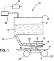
図1を参照すれば、インクジェット装置10は、供給インク12を入れている液溜め11及び液溜め11から圧力チャンバ14に通じる液路13を備える。アクチュエータ15,例えば圧電変換器が圧力チャンバ14に重なる。アクチュエータは、インクに力を加えて圧力チャンバ14からノズルプレート18のノズル開口18に通じる液路16を通し、ノズル17から基板20に向けてインク液滴19を射出させるために使用できる。動作中、インクジェット装置10及び基板20は互いに対して移動することができる。例えば、基板はロール22及び23の間を移動させられる連続ウエブとすることができる。ノズルプレート18のノズル17のアレイからの液滴の選択的射出によって、所望の画像が基板上につくられる。
Referring to FIG. 1, the
インクジェット装置は、システムが液滴を射出していないときのノズル開口近傍のインクメニスカスにおける動作圧力も制御する。図示される実施形態において、圧力制御は、液溜め11内のインク12の上方のヘッドスペース9に真空を与える、メカニカルポンプのような真空源30によって与えられる。真空は、重力によってノズル開口17を通るインクの滴下を防止するために、インクを介してノズル開口に伝えられる。コントローラ32,例えばコンピュータコントローラが、液溜め11のインク上方の真空を監視し、液溜めを所望の真空に維持するために真空源30を制御する。別の実施形態において、真空源はインク液溜めをノズル開口の下に配置してノズル開口近傍に真空を生じさせることによって与えられる。インクレベルモニタが、プリント動作中にインクが消費されるとともに低下するインクレベルを検出し、よってノズルにおける真空を高める。コントローラがインクレベルを監視し、インクが所望のレベルより低下したときに真空を所望の動作範囲内に維持するために、大量容器からインクを液溜めに補充する。メニスカスの真空がノズルの毛管作用力に打ち勝つに十分に離して液溜めがノズルの下方に配置されている別の実施形態においては、インクに圧力を加えてノズル開口近傍のメニスカスを維持することができる。実施形態において、動作真空は約0.5〜約10inwgに維持される。
The ink jet device also controls the operating pressure at the ink meniscus near the nozzle opening when the system is not ejecting droplets. In the illustrated embodiment, pressure control is provided by a
インク噴射中、インクはノズルプレート上に溜ることができる。時間の経過とともに、インクはプリントエラーを生じさせる液塊を形成し得る。例えば、ノズル開口の縁端近傍の液塊は、射出される液滴の軌道、速度または体積に影響を与え得る。また、液塊は印刷基板20上に落下して無意味なマークを生じさせるように十分に大きくもなることもできるであろう。液塊はノズルプレート18の表面から十分遠くまで突き出し、印刷基板20に接触するようになって、印刷基板20上に汚れを生じさせることもできるであろう。
During ink ejection, ink can accumulate on the nozzle plate. Over time, the ink can form liquid masses that cause print errors. For example, liquid mass near the edge of the nozzle opening can affect the trajectory, velocity or volume of the ejected droplet. The liquid mass could also be large enough to drop onto the printed
図1Aも参照すれば、ノズルプレート18は密間隔ノズル開口17のアレイを有し、それぞれのノズル開口17はウエル40内に配置される。図1Bも参照すれば、図示される実施形態において、ノズル開口17はウエル40の床面42に画成され、床面42の中心に配置される。ウエルの床面42は、ノズルプレートの面46まで外側に延びる、ウエルの壁44まで拡がる。
Referring also to FIG. 1A, the
ウエルの幅WW,深さdW及びウエル壁とノズル開口周縁の間隔Sを含む、ウエルの寸法は、残余インクを制御するように選ばれる。インク50がウエルに配されると、メニスカス52が形成される。動作圧力(矢印54)の条件の下でメニスカスは、ノズル開口の縁端において、ノズル幅WNに比較して小さい深さdmを有する。予測可能なメニスカス形状により確実な噴射が得られる。浅いメニスカス深さにより液滴の方向または速度に実質的に影響することのない噴射が得られる。さらに、間隔Sは、ノズルプレート18の面46上の残余インクは液滴の形成または射出に影響する可能性を低めるように選ばれる。
Well dimensions, including well width W W , depth d W, and spacing S between the well wall and the nozzle opening periphery, are selected to control the residual ink. When the
図2〜2Cを参照すれば、ウエル幅WWが大きくなり、動作圧力が変化するときのメニスカスへの効果が示される。MH,MI及びMLでそれぞれが表される、高真空圧力、中真空圧力及び低真空圧力におけるメニスカスが示される。ノズル開口にわたるメニスカス深さは、ウエル幅が大きくなるにつれて減少する。特に図2を参照すれば、いずれの圧力においてもメニスカスはノズル開口全体にかかる。高真空圧力において、メニスカス深さは比較的浅く、浅いメニスカスは一般に噴射に望ましい。低真空圧力において、メニスカス深さは大きくなり、深いメニスカスは最適ではない噴射を生じ得る。この場合、ウエル深さを小さくしてメニスカス深さを浅くすることができる。図2Aを参照すれば、メニスカスは、高真空圧力及び中真空圧力において選ばれた深さにあり、低真空圧力において最適ではない深さにある。図2Bを参照すれば、メニスカスは、中真空圧力において望ましい動作深さにあり、低真空圧力において最適ではない深さにあり、高真空圧力においては浅すぎて最適ではなくなっている。高真空圧力においては、メニスカスがノズル開口全体にわたっては形成されていない。インクのほとんどがノズル開口に引き込まれ、若干の残余インクがウエルに保持される。図2Cを参照すれば、いずれの動作圧力においてもメニスカスがノズル開口全体にわたっては形成されていない。液体はウエル床面と壁の間の角に集まり、ノズル開口の周縁に沿って拡がる。この状態は、ノズル開口の周縁にある液体が噴射に影響を与えるから、最適ではない。図2〜2Cにおいて、メニスカスの曲率半径Rは、2×表面張力/圧力によって計算される。メニスカス液体は30ダイン/cmの表面張力を有し、動作圧力は2,4及び6inwgである。寸法はmmである。 Referring to FIG. 2~2C, well width W W is increased, the effect of the meniscus when the operating pressure is varied is shown. M H, respectively M I and M L is expressed, a high vacuum pressure, the meniscus in the medium vacuum pressure and low vacuum pressures are shown. The meniscus depth across the nozzle opening decreases as the well width increases. With particular reference to FIG. 2, the meniscus is applied to the entire nozzle opening at any pressure. At high vacuum pressures, the meniscus depth is relatively shallow and a shallow meniscus is generally desirable for jetting. At low vacuum pressures, the meniscus depth increases and a deep meniscus can cause suboptimal injection. In this case, the meniscus depth can be reduced by reducing the well depth. Referring to FIG. 2A, the meniscus is at a selected depth at high and medium vacuum pressures and at a depth that is not optimal at low vacuum pressures. Referring to FIG. 2B, the meniscus is at the desired operating depth at medium vacuum pressure, at a suboptimal depth at low vacuum pressure, and too shallow and less optimal at high vacuum pressure. At high vacuum pressure, no meniscus is formed over the entire nozzle opening. Most of the ink is drawn into the nozzle openings and some residual ink is retained in the wells. Referring to FIG. 2C, no meniscus is formed over the entire nozzle opening at any operating pressure. The liquid collects at the corner between the well floor and the wall and spreads along the periphery of the nozzle opening. This condition is not optimal because the liquid at the periphery of the nozzle opening affects ejection. 2-2C, the radius of curvature R of the meniscus is calculated by 2 * surface tension / pressure. The meniscus liquid has a surface tension of 30 dynes / cm and the operating pressure is 2, 4 and 6 inwg. The dimension is mm.
ウエル壁とノズル周縁の間隔Sは、ノズルプレート面上の残余インクが噴射に影響を与える可能性を低める距離を与える。実施形態において、間隔Sはノズル幅WNの約20%ないしそれより大きく、例えば25〜100%である。ウエルの寸法によりノズル開口にわたる望ましいメニスカス深さが得られる。実施形態において、ウエルは、ウエルが与えられた表面張力をもつ液体で満たされ、ノズルが与えられた動作圧力範囲内にあるときに、ノズル開口端にかかる、ノズル幅の約1〜15%のメニスカス深さをノズル開口の縁端にわたって与える(ウエルはウエルの壁を実質的に覆うに十分な液体があるときに液体で満たされている)。実施形態において、ノズルの縁端で測定されるメニスカス深さは、ノズル開口の約1〜25%である。実施形態において、所望のメニスカス深さは所望の動作圧力範囲にわたって維持される。実施形態において、動作圧力は約−0.5〜−10inwg,例えば、−2〜―4または−6inwgである。実施形態において、液体は約20〜40ダイン/cmの表面張力を有する。ノズル幅に対するウエル幅の比は約1.4〜約2.8,例えば1.5〜約1.7である。ウエル深さはノズル開口幅の約0.15〜0.5である。ウエル寸法は一定の量の残余インクを入れるに必要な容積を収めるように選ぶこともできる。非円形ノズル開口及び/またはウエル、例えば非対称であるかまたは不規則な形状寸法に対しては、ウエル及びノズルの幅は最小値で測定される。深さが変化するウエルに対しては、ウエル深さはノズル開口とノズルプレートの間で測定される。実施形態において、ノズル幅は約200μmないしそれより小さく、例えば約10〜30μmであり、ノズルピッチは約100ノズル/インチ(約3.9ノズル/mm)ないしそれより短く、例えば300ノズル/インチ(約11.8ノズル/mm)であって、液滴体積は約1〜70pLである。実施形態において、液体は約1センチポアズから約40センチポアズの粘度を有する(1センチポアズ=10−11N・秒/m2)。 The spacing S between the well wall and the nozzle periphery gives a distance that reduces the possibility that residual ink on the nozzle plate surface will affect the ejection. In embodiments, the spacing S is about 20% to greater than that of the nozzle width W N, for example 25 to 100%. The well size provides the desired meniscus depth across the nozzle opening. In an embodiment, the well is filled with a liquid having a given surface tension and about 1-15% of the nozzle width over the nozzle open end when the nozzle is within a given operating pressure range. Meniscus depth is provided across the edge of the nozzle opening (the well is filled with liquid when there is sufficient liquid to substantially cover the wall of the well). In an embodiment, the meniscus depth measured at the nozzle edge is about 1-25% of the nozzle opening. In an embodiment, the desired meniscus depth is maintained over a desired operating pressure range. In embodiments, the operating pressure is about −0.5 to −10 inwg, such as −2 to −4 or −6 inwg. In embodiments, the liquid has a surface tension of about 20-40 dynes / cm. The ratio of well width to nozzle width is about 1.4 to about 2.8, for example 1.5 to about 1.7. The well depth is about 0.15 to 0.5 of the nozzle opening width. The well dimensions can also be chosen to accommodate the volume required to hold a certain amount of residual ink. For non-circular nozzle openings and / or wells, eg, asymmetric or irregular geometries, the well and nozzle widths are measured at a minimum. For wells of varying depth, the well depth is measured between the nozzle opening and the nozzle plate. In an embodiment, the nozzle width is about 200 μm or less, such as about 10-30 μm, and the nozzle pitch is about 100 nozzles / inch (about 3.9 nozzles / mm) or less, such as 300 nozzles / inch ( About 11.8 nozzles / mm) and the drop volume is about 1-70 pL. In embodiments, the liquid has a viscosity of about 1 centipoise to about 40 centipoise (1 centipoise = 10 −11 N · sec / m 2 ).
一実施形態における図3を参照すれば、ノズルプレート70は、円形のノズル開口72,及び楕円形のウエル74を有する。楕円の長軸ALは、ノズル面を手によるかまたは機械による清掃作業において拭うかまたは洗うことができる方向(矢印76)に沿って配置される。楕円形ウエルは長軸ALの長さに沿ってノズル開口から離れた場所に屑を集め、これにより、清掃中にウエルに運び入れられる屑によるノズル開口の閉塞の可能性が低められる。一実施形態において、長軸に沿うウエルの長さは約300〜600μmであり、短軸にわたるウエルの幅は約50〜70μmである。別の実施形態において、ノズル開口はウエルの形状寸法に整合するかまたは整合しない非円形の形状寸法を有する。さらに、ノズル開口はウエル中心からずらすことができる。実施形態において、ウエル深さはノズル開口とウエル周縁がノズルプレートと会合する場所の間で変わることができる。
Referring to FIG. 3 in one embodiment, the
ウエル及び/またはノズル開口は、機械加工、レーザアブレーションあるいは化学エッチングまたはプラズマエッチングで形成することができる。ウエルは成形によって、例えばプラスチック素子で形成することもできる。ウエル及びノズル開口は、共通の構体または組み立てられる別々の構体に形成することができる。例えば、ノズル開口はインク流路の別のコンポーネントを画成する構体に形成され、ウエルはノズル開口を画成する構体と組み立てられる別の構体に形成される。別の実施形態において、ウエル、ノズル開口及び圧力チャンバは共通の構体に形成される。構体は金属、炭素、またはシリコン材料、例えばシリコンまたは二酸化ケイ素などの、エッチング可能な材料とすることができる。エッチング法を用いるプリントヘッドコンポーネントの形成は、2002年7月3日に出願された米国特許出願第10/189947号の明細書、及び2003年10月10日に出願された米国特許出願第60/510459号の明細書に詳細に説明されており、これらの明細書のそれぞれの全内容は本明細書に参照として含まれる。実施形態において、ウエルは非湿潤性被覆を有することができる。 Wells and / or nozzle openings can be formed by machining, laser ablation or chemical or plasma etching. The well can also be formed by molding, for example with a plastic element. The well and nozzle openings can be formed in a common structure or separate structures to be assembled. For example, the nozzle opening is formed in a structure that defines another component of the ink flow path, and the well is formed in another structure that is assembled with the structure that defines the nozzle opening. In another embodiment, the well, nozzle opening and pressure chamber are formed in a common structure. The structure can be an etchable material such as a metal, carbon, or silicon material, eg, silicon or silicon dioxide. The formation of printhead components using an etching method is described in US patent application Ser. No. 10/189947, filed Jul. 3, 2002, and US Patent Application No. 60/90, filed Oct. 10, 2003. The details of each of these specifications are included herein by reference. In embodiments, the well can have a non-wetting coating.
まだ別の実施形態がある。例えば、プリント動作においてはインクを噴射させることができるが、プリントヘッドはインク以外の液体を射出するために利用することができる。例えば、被着される液滴はUV硬化性またはその他の輻射線硬化性の材料、あるいは液滴として送出され得るその他の材料、例えば化学的または生物学的液体とすることができる。例えば、説明される装置は、精密計量分配システムの一部とすることができよう。アクチュエータは電気機械アクチュエータまたは熱アクチュエータとすることができる。ウエル配列は、2003年12月30日に出願された米国特許出願第10/749829号の明細書に説明されるアパーチャ、2003年12月30日に出願された米国特許出願第10/749816号の明細書に説明される突起及び/または2003年12月30日に出願された米国特許出願第10/749833号の明細書に説明されるチャネルのような、その他の残余液制御態様と組み合わせて用いることができる。例えば、一連の突起またはチャネルをウエル内部に、またはウエル近傍のノズル面に、例えばウエルを囲んで、設けることができる。ウエル内にまたはノズル面にアパーチャを設けることができる。液体制御構造を、クリーニング液がノズルプレートに与えられ、拭い取られる、手動または自動の洗浄及び拭取りシステムと組み合わせることができる。クリーニング構造は噴射残余インクではなくクリーニング液及び屑を集めることができる。 There are still other embodiments. For example, ink can be ejected in a printing operation, but the print head can be used to eject liquids other than ink. For example, the deposited droplets can be UV curable or other radiation curable materials, or other materials that can be delivered as droplets, such as chemical or biological fluids. For example, the described device could be part of a precision dispensing system. The actuator can be an electromechanical actuator or a thermal actuator. Well arrays are described in US patent application Ser. No. 10/749829 filed Dec. 30, 2003, US patent application Ser. No. 10 / 7,816 filed Dec. 30, 2003. Used in combination with other residual liquid control aspects such as protrusions described in the specification and / or channels described in US patent application Ser. No. 10 / 7,833, filed Dec. 30, 2003. be able to. For example, a series of protrusions or channels can be provided inside the well or on the nozzle surface near the well, eg, surrounding the well. Apertures can be provided in the well or on the nozzle face. The liquid control structure can be combined with a manual or automatic cleaning and wiping system in which cleaning liquid is applied to the nozzle plate and wiped off. The cleaning structure can collect cleaning liquid and debris rather than jetted residual ink.
また別の実施形態は添付される特許請求の範囲内にある。 Further embodiments are within the scope of the appended claims.
9 ヘッドスペース
10 インクジェット装置
11 液溜め
12 インク
13,16 液路
14 圧力チャンバ
15 アクチュエータ
17 ノズル
18 ノズルプレート
19 インク液滴
20 基板
22,23 ロール
30 真空源
32 コントローラ
40 ウエル
DESCRIPTION OF SYMBOLS 9
Claims (40)
液体に圧力を加えて、ウエル内に配置されたノズル開口から液滴を射出するための液体流路を有するプリントヘッドを提供する工程、及び
メニスカスを形成するために前記ノズル開口から前記ウエルに液体を供給する工程、
を有してなり、
前記ウエルが、前記プリントヘッドの外側表面上に周縁部を有し、
前記ウエルが液体で満たされているときに、前記メニスカスが、前記ノズル開口の幅の約1〜15%に等しい、前記ノズル開口の周縁の上方の液体深さを定めるとともに、前記ウエルの周縁部に接触することを特徴とする方法。In the method of droplet ejection,
Providing a print head having a liquid flow path for applying a pressure to the liquid to eject droplets from a nozzle opening disposed in the well; and a liquid from the nozzle opening to the well to form a meniscus Supplying the process,
Having
The well has a peripheral edge on the outer surface of the printhead;
When the well is filled with liquid, the meniscus defines a liquid depth above the periphery of the nozzle opening equal to about 1-15% of the width of the nozzle opening and the periphery of the well A method characterized by touching .
Applications Claiming Priority (7)
| Application Number | Priority Date | Filing Date | Title |
|---|---|---|---|
| US10/749,816 US7121646B2 (en) | 2003-12-30 | 2003-12-30 | Drop ejection assembly |
| US10/749,833 | 2003-12-30 | ||
| US10/749,622 US7168788B2 (en) | 2003-12-30 | 2003-12-30 | Drop ejection assembly |
| US10/749,622 | 2003-12-30 | ||
| US10/749,833 US7303259B2 (en) | 2003-12-30 | 2003-12-30 | Drop ejection assembly |
| US10/749,816 | 2003-12-30 | ||
| PCT/US2004/043775 WO2005065330A2 (en) | 2003-12-30 | 2004-12-29 | Drop ejection assembly |
Publications (3)
| Publication Number | Publication Date |
|---|---|
| JP2007516877A JP2007516877A (en) | 2007-06-28 |
| JP2007516877A5 JP2007516877A5 (en) | 2008-03-21 |
| JP4936900B2 true JP4936900B2 (en) | 2012-05-23 |
Family
ID=34753712
Family Applications (1)
| Application Number | Title | Priority Date | Filing Date |
|---|---|---|---|
| JP2006547519A Active JP4936900B2 (en) | 2003-12-30 | 2004-12-29 | Droplet ejection assembly |
Country Status (5)
| Country | Link |
|---|---|
| EP (1) | EP1706271B1 (en) |
| JP (1) | JP4936900B2 (en) |
| KR (1) | KR101211012B1 (en) |
| AT (1) | ATE537971T1 (en) |
| WO (1) | WO2005065330A2 (en) |
Families Citing this family (1)
| Publication number | Priority date | Publication date | Assignee | Title |
|---|---|---|---|---|
| GB201420264D0 (en) * | 2014-11-14 | 2014-12-31 | The Technology Partnership Plc | Non-contact liquid printing |
Citations (7)
| Publication number | Priority date | Publication date | Assignee | Title |
|---|---|---|---|---|
| JPH08187874A (en) * | 1995-01-13 | 1996-07-23 | Canon Inc | Ink tank and ink jet recording device placing the same |
| JPH10128231A (en) * | 1996-10-29 | 1998-05-19 | Dainippon Toryo Co Ltd | Coating method of substrate |
| JPH1158741A (en) * | 1994-03-21 | 1999-03-02 | Spectra Inc | Simple ink jet head |
| JP2001270111A (en) * | 2000-03-24 | 2001-10-02 | Seiko Epson Corp | Method and apparatus for jetting liquid drop |
| JP2003508278A (en) * | 1999-09-09 | 2003-03-04 | ヒューレット・パッカード・カンパニー | Print head |
| JP2003154655A (en) * | 2001-11-22 | 2003-05-27 | Canon Inc | Liquid discharge head |
| JP2003182092A (en) * | 2001-12-19 | 2003-07-03 | Konica Corp | Inkjet recorder |
Family Cites Families (6)
| Publication number | Priority date | Publication date | Assignee | Title |
|---|---|---|---|---|
| DE3048259A1 (en) * | 1980-12-20 | 1982-07-29 | Philips Patentverwaltung Gmbh, 2000 Hamburg | "NOZZLE FOR INK JET PRINTER" |
| JPH06286129A (en) * | 1992-02-20 | 1994-10-11 | Seikosha Co Ltd | Ink jet head |
| US6254219B1 (en) * | 1995-10-25 | 2001-07-03 | Hewlett-Packard Company | Inkjet printhead orifice plate having related orifices |
| WO1999015337A1 (en) * | 1997-09-22 | 1999-04-01 | Cimeo Precision Co., Ltd. | Ink-jet head nozzle plate, its manufacturing method and ink-jet head |
| US6139136A (en) * | 1997-12-17 | 2000-10-31 | Pitney Bowes Inc. | Ink supply system including a multiple level ink reservoir for ink jet printing |
| CA2436011C (en) * | 2001-11-22 | 2009-03-10 | Canon Kabushiki Kaisha | Liquid ejection head |
-
2004
- 2004-12-29 AT AT04815777T patent/ATE537971T1/en active
- 2004-12-29 EP EP04815777A patent/EP1706271B1/en active Active
- 2004-12-29 WO PCT/US2004/043775 patent/WO2005065330A2/en active Application Filing
- 2004-12-29 JP JP2006547519A patent/JP4936900B2/en active Active
-
2006
- 2006-07-31 KR KR1020067015514A patent/KR101211012B1/en active IP Right Grant
Patent Citations (7)
| Publication number | Priority date | Publication date | Assignee | Title |
|---|---|---|---|---|
| JPH1158741A (en) * | 1994-03-21 | 1999-03-02 | Spectra Inc | Simple ink jet head |
| JPH08187874A (en) * | 1995-01-13 | 1996-07-23 | Canon Inc | Ink tank and ink jet recording device placing the same |
| JPH10128231A (en) * | 1996-10-29 | 1998-05-19 | Dainippon Toryo Co Ltd | Coating method of substrate |
| JP2003508278A (en) * | 1999-09-09 | 2003-03-04 | ヒューレット・パッカード・カンパニー | Print head |
| JP2001270111A (en) * | 2000-03-24 | 2001-10-02 | Seiko Epson Corp | Method and apparatus for jetting liquid drop |
| JP2003154655A (en) * | 2001-11-22 | 2003-05-27 | Canon Inc | Liquid discharge head |
| JP2003182092A (en) * | 2001-12-19 | 2003-07-03 | Konica Corp | Inkjet recorder |
Also Published As
| Publication number | Publication date |
|---|---|
| KR101211012B1 (en) | 2012-12-11 |
| EP1706271A4 (en) | 2009-08-19 |
| KR20060127953A (en) | 2006-12-13 |
| ATE537971T1 (en) | 2012-01-15 |
| WO2005065330A2 (en) | 2005-07-21 |
| EP1706271B1 (en) | 2011-12-21 |
| EP1706271A2 (en) | 2006-10-04 |
| JP2007516877A (en) | 2007-06-28 |
| WO2005065330A3 (en) | 2006-03-02 |
Similar Documents
| Publication | Publication Date | Title |
|---|---|---|
| JP4959013B2 (en) | Droplet ejection assembly | |
| US8287093B2 (en) | Drop ejection assembly | |
| JP5732526B2 (en) | Fluid ejection device | |
| US10717274B2 (en) | Fluid ejection device | |
| US7121646B2 (en) | Drop ejection assembly | |
| JP2007516879A5 (en) | ||
| JP4936900B2 (en) | Droplet ejection assembly | |
| US7168788B2 (en) | Drop ejection assembly | |
| US7303259B2 (en) | Drop ejection assembly |
Legal Events
| Date | Code | Title | Description |
|---|---|---|---|
| A521 | Request for written amendment filed |
Free format text: JAPANESE INTERMEDIATE CODE: A523 Effective date: 20080104 |
|
| A621 | Written request for application examination |
Free format text: JAPANESE INTERMEDIATE CODE: A621 Effective date: 20080104 |
|
| A521 | Request for written amendment filed |
Free format text: JAPANESE INTERMEDIATE CODE: A523 Effective date: 20080131 |
|
| A977 | Report on retrieval |
Free format text: JAPANESE INTERMEDIATE CODE: A971007 Effective date: 20101015 |
|
| A131 | Notification of reasons for refusal |
Free format text: JAPANESE INTERMEDIATE CODE: A131 Effective date: 20101026 |
|
| A601 | Written request for extension of time |
Free format text: JAPANESE INTERMEDIATE CODE: A601 Effective date: 20110126 |
|
| A601 | Written request for extension of time |
Free format text: JAPANESE INTERMEDIATE CODE: A601 Effective date: 20110127 |
|
| A602 | Written permission of extension of time |
Free format text: JAPANESE INTERMEDIATE CODE: A602 Effective date: 20110202 |
|
| A602 | Written permission of extension of time |
Free format text: JAPANESE INTERMEDIATE CODE: A602 Effective date: 20110203 |
|
| A521 | Request for written amendment filed |
Free format text: JAPANESE INTERMEDIATE CODE: A523 Effective date: 20110426 |
|
| TRDD | Decision of grant or rejection written | ||
| A01 | Written decision to grant a patent or to grant a registration (utility model) |
Free format text: JAPANESE INTERMEDIATE CODE: A01 Effective date: 20120124 |
|
| A01 | Written decision to grant a patent or to grant a registration (utility model) |
Free format text: JAPANESE INTERMEDIATE CODE: A01 |
|
| A61 | First payment of annual fees (during grant procedure) |
Free format text: JAPANESE INTERMEDIATE CODE: A61 Effective date: 20120221 |
|
| FPAY | Renewal fee payment (event date is renewal date of database) |
Free format text: PAYMENT UNTIL: 20150302 Year of fee payment: 3 |
|
| R150 | Certificate of patent or registration of utility model |
Ref document number: 4936900 Country of ref document: JP Free format text: JAPANESE INTERMEDIATE CODE: R150 Free format text: JAPANESE INTERMEDIATE CODE: R150 |
|
| R250 | Receipt of annual fees |
Free format text: JAPANESE INTERMEDIATE CODE: R250 |
|
| R250 | Receipt of annual fees |
Free format text: JAPANESE INTERMEDIATE CODE: R250 |
|
| R250 | Receipt of annual fees |
Free format text: JAPANESE INTERMEDIATE CODE: R250 |
|
| R250 | Receipt of annual fees |
Free format text: JAPANESE INTERMEDIATE CODE: R250 |
|
| R250 | Receipt of annual fees |
Free format text: JAPANESE INTERMEDIATE CODE: R250 |
|
| R250 | Receipt of annual fees |
Free format text: JAPANESE INTERMEDIATE CODE: R250 |
|
| R250 | Receipt of annual fees |
Free format text: JAPANESE INTERMEDIATE CODE: R250 |
|
| R250 | Receipt of annual fees |
Free format text: JAPANESE INTERMEDIATE CODE: R250 |
|
| R250 | Receipt of annual fees |
Free format text: JAPANESE INTERMEDIATE CODE: R250 |
|
| R250 | Receipt of annual fees |
Free format text: JAPANESE INTERMEDIATE CODE: R250 |