EP1706270B1 - Drop ejection assembly - Google Patents
Drop ejection assembly Download PDFInfo
- Publication number
- EP1706270B1 EP1706270B1 EP04817071A EP04817071A EP1706270B1 EP 1706270 B1 EP1706270 B1 EP 1706270B1 EP 04817071 A EP04817071 A EP 04817071A EP 04817071 A EP04817071 A EP 04817071A EP 1706270 B1 EP1706270 B1 EP 1706270B1
- Authority
- EP
- European Patent Office
- Prior art keywords
- apertures
- nozzle opening
- fluid
- less
- nozzle
- Prior art date
- Legal status (The legal status is an assumption and is not a legal conclusion. Google has not performed a legal analysis and makes no representation as to the accuracy of the status listed.)
- Active
Links
- 239000012530 fluid Substances 0.000 claims abstract description 33
- 239000002699 waste material Substances 0.000 claims abstract description 28
- 239000000463 material Substances 0.000 claims description 13
- 238000000034 method Methods 0.000 claims description 10
- 238000004891 communication Methods 0.000 claims description 6
- 239000011248 coating agent Substances 0.000 claims description 3
- 238000000576 coating method Methods 0.000 claims description 3
- 239000002210 silicon-based material Substances 0.000 claims description 3
- XLYOFNOQVPJJNP-UHFFFAOYSA-N water Substances O XLYOFNOQVPJJNP-UHFFFAOYSA-N 0.000 claims description 3
- 239000000758 substrate Substances 0.000 description 10
- 230000005499 meniscus Effects 0.000 description 7
- 238000007639 printing Methods 0.000 description 7
- 238000004140 cleaning Methods 0.000 description 4
- XUIMIQQOPSSXEZ-UHFFFAOYSA-N Silicon Chemical compound [Si] XUIMIQQOPSSXEZ-UHFFFAOYSA-N 0.000 description 3
- 238000006073 displacement reaction Methods 0.000 description 3
- 229910052710 silicon Inorganic materials 0.000 description 3
- 239000010703 silicon Substances 0.000 description 3
- VYPSYNLAJGMNEJ-UHFFFAOYSA-N Silicium dioxide Chemical compound O=[Si]=O VYPSYNLAJGMNEJ-UHFFFAOYSA-N 0.000 description 2
- 230000002745 absorbent Effects 0.000 description 2
- 239000002250 absorbent Substances 0.000 description 2
- 230000000712 assembly Effects 0.000 description 2
- 238000000429 assembly Methods 0.000 description 2
- -1 e.g. Substances 0.000 description 2
- 230000000694 effects Effects 0.000 description 2
- 238000005530 etching Methods 0.000 description 2
- 230000005484 gravity Effects 0.000 description 2
- 238000002360 preparation method Methods 0.000 description 2
- 238000005086 pumping Methods 0.000 description 2
- 239000004065 semiconductor Substances 0.000 description 2
- 239000000126 substance Substances 0.000 description 2
- OKTJSMMVPCPJKN-UHFFFAOYSA-N Carbon Chemical compound [C] OKTJSMMVPCPJKN-UHFFFAOYSA-N 0.000 description 1
- 229920005830 Polyurethane Foam Polymers 0.000 description 1
- 229910052581 Si3N4 Inorganic materials 0.000 description 1
- 239000004809 Teflon Substances 0.000 description 1
- 229920006362 Teflon® Polymers 0.000 description 1
- 238000005452 bending Methods 0.000 description 1
- 239000013060 biological fluid Substances 0.000 description 1
- 229910052799 carbon Inorganic materials 0.000 description 1
- 238000003486 chemical etching Methods 0.000 description 1
- 230000001351 cycling effect Effects 0.000 description 1
- 238000000151 deposition Methods 0.000 description 1
- 238000001035 drying Methods 0.000 description 1
- 229920002313 fluoropolymer Polymers 0.000 description 1
- 239000004811 fluoropolymer Substances 0.000 description 1
- 239000006260 foam Substances 0.000 description 1
- 238000011065 in-situ storage Methods 0.000 description 1
- 238000002347 injection Methods 0.000 description 1
- 239000007924 injection Substances 0.000 description 1
- 238000001746 injection moulding Methods 0.000 description 1
- 238000007641 inkjet printing Methods 0.000 description 1
- 238000000608 laser ablation Methods 0.000 description 1
- 238000003754 machining Methods 0.000 description 1
- 239000002184 metal Substances 0.000 description 1
- 238000000465 moulding Methods 0.000 description 1
- 230000007935 neutral effect Effects 0.000 description 1
- 238000001020 plasma etching Methods 0.000 description 1
- 229920000642 polymer Polymers 0.000 description 1
- 229920002635 polyurethane Polymers 0.000 description 1
- 239000004814 polyurethane Substances 0.000 description 1
- 239000011496 polyurethane foam Substances 0.000 description 1
- 238000011176 pooling Methods 0.000 description 1
- 239000011148 porous material Substances 0.000 description 1
- 239000002243 precursor Substances 0.000 description 1
- 230000005855 radiation Effects 0.000 description 1
- 239000000377 silicon dioxide Substances 0.000 description 1
- 235000012239 silicon dioxide Nutrition 0.000 description 1
- HQVNEWCFYHHQES-UHFFFAOYSA-N silicon nitride Chemical compound N12[Si]34N5[Si]62N3[Si]51N64 HQVNEWCFYHHQES-UHFFFAOYSA-N 0.000 description 1
- BFKJFAAPBSQJPD-UHFFFAOYSA-N tetrafluoroethene Chemical compound FC(F)=C(F)F BFKJFAAPBSQJPD-UHFFFAOYSA-N 0.000 description 1
- 238000011144 upstream manufacturing Methods 0.000 description 1
- 238000005406 washing Methods 0.000 description 1
Images


Classifications
-
- B—PERFORMING OPERATIONS; TRANSPORTING
- B41—PRINTING; LINING MACHINES; TYPEWRITERS; STAMPS
- B41J—TYPEWRITERS; SELECTIVE PRINTING MECHANISMS, i.e. MECHANISMS PRINTING OTHERWISE THAN FROM A FORME; CORRECTION OF TYPOGRAPHICAL ERRORS
- B41J2/00—Typewriters or selective printing mechanisms characterised by the printing or marking process for which they are designed
- B41J2/005—Typewriters or selective printing mechanisms characterised by the printing or marking process for which they are designed characterised by bringing liquid or particles selectively into contact with a printing material
- B41J2/01—Ink jet
- B41J2/135—Nozzles
- B41J2/14—Structure thereof only for on-demand ink jet heads
- B41J2/14201—Structure of print heads with piezoelectric elements
-
- B—PERFORMING OPERATIONS; TRANSPORTING
- B41—PRINTING; LINING MACHINES; TYPEWRITERS; STAMPS
- B41J—TYPEWRITERS; SELECTIVE PRINTING MECHANISMS, i.e. MECHANISMS PRINTING OTHERWISE THAN FROM A FORME; CORRECTION OF TYPOGRAPHICAL ERRORS
- B41J2/00—Typewriters or selective printing mechanisms characterised by the printing or marking process for which they are designed
- B41J2/005—Typewriters or selective printing mechanisms characterised by the printing or marking process for which they are designed characterised by bringing liquid or particles selectively into contact with a printing material
- B41J2/01—Ink jet
- B41J2/015—Ink jet characterised by the jet generation process
- B41J2/04—Ink jet characterised by the jet generation process generating single droplets or particles on demand
- B41J2/045—Ink jet characterised by the jet generation process generating single droplets or particles on demand by pressure, e.g. electromechanical transducers
-
- B—PERFORMING OPERATIONS; TRANSPORTING
- B41—PRINTING; LINING MACHINES; TYPEWRITERS; STAMPS
- B41J—TYPEWRITERS; SELECTIVE PRINTING MECHANISMS, i.e. MECHANISMS PRINTING OTHERWISE THAN FROM A FORME; CORRECTION OF TYPOGRAPHICAL ERRORS
- B41J2/00—Typewriters or selective printing mechanisms characterised by the printing or marking process for which they are designed
- B41J2/005—Typewriters or selective printing mechanisms characterised by the printing or marking process for which they are designed characterised by bringing liquid or particles selectively into contact with a printing material
- B41J2/01—Ink jet
- B41J2/135—Nozzles
- B41J2/14—Structure thereof only for on-demand ink jet heads
- B41J2/1433—Structure of nozzle plates
-
- B—PERFORMING OPERATIONS; TRANSPORTING
- B41—PRINTING; LINING MACHINES; TYPEWRITERS; STAMPS
- B41J—TYPEWRITERS; SELECTIVE PRINTING MECHANISMS, i.e. MECHANISMS PRINTING OTHERWISE THAN FROM A FORME; CORRECTION OF TYPOGRAPHICAL ERRORS
- B41J2/00—Typewriters or selective printing mechanisms characterised by the printing or marking process for which they are designed
- B41J2/005—Typewriters or selective printing mechanisms characterised by the printing or marking process for which they are designed characterised by bringing liquid or particles selectively into contact with a printing material
- B41J2/01—Ink jet
- B41J2/135—Nozzles
- B41J2/14—Structure thereof only for on-demand ink jet heads
- B41J2002/14475—Structure thereof only for on-demand ink jet heads characterised by nozzle shapes or number of orifices per chamber
Definitions
- This invention relates to ejecting drops.
- Ink jet printers are one type of apparatus for depositing drops on a substrate.
- Ink jet printers typically include an ink path from an ink supply to a nozzle path. The nozzle path terminates in a nozzle opening from which ink drops are ejected.
- Ink drop ejection is typically controlled by pressurizing ink in the ink path with an actuator, which may be, for example, a piezoelectric deflector, a thermal bubble jet generator, or an electrostatically deflected element.
- An actuator which may be, for example, a piezoelectric deflector, a thermal bubble jet generator, or an electrostatically deflected element.
- a typical print assembly has an array of ink paths with corresponding nozzle openings and associated actuators. Drop ejection from each nozzle opening can be independently controlled.
- each actuator is fired to selectively eject a drop at a specific pixel location of an image as the print assembly and a printing substrate are moved relative to one another.
- the nozzle openings typically have a diameter of 50 microns or less, e.g. around 25 microns, are separated at a pitch of 100-300 nozzles/inch, have a resolution of 100 to 3000 dpi or more, and provide drops with a volume of about 1 to 120 picoliters (pL) or less.
- Drop ejection frequency is typically 10 kHz or more.
- Hoisington et al. U.S. Patent No. 5,265,315 describes a print assembly that has a semiconductor body and a piezoelectric actuator.
- the body is made of silicon, which is etched to define ink chambers. Nozzle openings are defined by a separate nozzle plate, which is attached to the silicon body.
- the piezoelectric actuator has a layer of piezoelectric material, which changes geometry, or bends, in response to an applied voltage. The bending of the piezoelectric layer pressurizes ink in a pumping chamber located along the ink path.
- Piezoelectric ink jet print assemblies are also described in Fishbeck et al. U.S. Patent No. 4,825,227 , Hine U.S. Patent No. 4,937,598 , Moynihan et al. U.S. Patent No. 5,659,346 and Hoisington U.S. Patent No. 5,757,391 , the entire contents of which are hereby incorporated by reference.
- GB-A-2339170 discloses a drop ejection device according to the preamble of claim 1.
- the invention features a drop ejection device according to claim 1
- the invention features a method of ejecting fluid according to claim 16.
- Embodiments may include one or more of the following advantages.
- Printing errors can be reduced by controlling waste ink that collects adjacent ejection nozzles, where it could interfere with ink ejection, or become disposed on the substrate and obscure an image.
- the waste ink can be controlled by directing and containing it in controlled locations by using vacuum, capillary forces, gravity and/or surface tension effects.
- the waste ink can be recycled to an ink supply, or directed to a waste container off the nozzle plate surface.
- the waste control aperture features can be formed accurately on a nozzle plate by, e.g., etching a semiconductor material such as a silicon material.
- an ink jet apparatus 10 includes a reservoir 11 containing a supply of ink 12 and a passage 13 leading from the reservoir 11 to a pressure chamber 14.
- An actuator 15, e.g., a piezoelectric transducer covers the pressure chamber 14.
- the actuator is operable to force ink from the pressure chamber 14 through a passage 16 leading to a nozzle opening 17 in an nozzle plate 18, causing a drop of ink 19 to be ejected from the nozzle 17 toward a substrate 20.
- the ink jet apparatus 10 and the substrate 20 can be moved relative to one another.
- the substrate can be a continuous web that is moved between rolls 22 and 23.
- the inkjet apparatus also controls the operating pressure at the ink meniscus proximate the nozzle openings when the system is not ejecting drops.
- pressure control is provided by a vacuum source 30 such as a mechanical pump that applies a vacuum to the headspace 9 over the ink 12 in the reservoir 11.
- the vacuum is communicated through the ink to the nozzle opening 17 to prevent ink from weeping through the nozzle opening by force of gravity.
- a controller 31 e.g. a computer controller, monitors the vacuum over the ink in the reservoir 11 and adjusts the source 30 to maintain a desired vacuum in the reservoir.
- a vacuum source is provided by arranging the ink reservoir below the nozzle openings to create a vacuum proximate the nozzle openings.
- An ink level monitor (not shown) detects the level of ink, which falls as ink is consumed during a printing operation and thus increases the vacuum at the nozzles.
- a controller monitors the ink level and refills the reservoir from a bulk container when ink falls below a desired level to maintain vacuum within a desired operation range.
- the ink in which the reservoir is located far enough below the nozzles that the vacuum of the meniscus overcomes the capillary force in the nozzle, the ink can be pressurized to maintain a meniscus proximate the nozzle openings. Variations in meniscus can cause variations in drop velocity and can lead to air injection or weeping.
- the operating vacuum maintained at the meniscus is about 0.5 to about 10 inwg, e.g., about 2 to about 6 inwg.
- nozzle 17, having a nozzle width, W N is surrounded by waste ink control apertures 32, having an aperture width, W A .
- the apertures generally surround the nozzle and are spaced a distance, S, from the periphery of the nozzle.
- the apertures communicate through a lumen 34 and an opening 36 with an ink passage upstream of the nozzle opening.
- ink may collect on the nozzle plate. Over time, ink can form puddles which cause printing errors. For example, puddles near the edge of a nozzle opening can effect the trajectory, velocity or volume of the ejected drops.
- the apertures 32 provide a region in which waste ink can collect to avoid forming excessive puddles. Ink can be drawn into the apertures 32 by capillary force and/or by vacuum produced by the piezoelectric actuator 15 and/or the vacuum source 30.
- FIG. 3 the operation of the ink control apertures during drop ejection is illustrated.
- the nozzle 17 is illustrated in a non-jetting condition in which an ink meniscus 24 forms in nozzle 17.
- ink is directed out of the nozzle opening 17 and a drop 19 is formed and ejected.
- ink may also protrude from apertures 32, but it is not ejected from the apertures.
- waste ink 38 may be deposited onto nozzle plate 18.
- waste ink can be disposed on the nozzle plate as the drop separates from the ink or back-splashes in flight or satellites drops can be directed back to the nozzle plate.
- the meniscus 24 is withdrawn by a vacuum.
- the vacuum may be created the vacuum source 30 and/or by the piezoelectric actuator as it is actuated from a pressurizing condition, in which the actuator pressurizes ink 12 in chamber 14 to eject a drop, to a neutral or negative condition in preparation for the next drop ejection.
- the vacuum on nozzle 17 is also communicated to ink control openings 32 so that waste ink is drawn into the openings 32 and through lumens 34 in a direction indicated by arrows 35.
- waste ink does not pool excessively on the nozzle plate.
- the nozzle plate, particularly the region 33 between the nozzle opening and the aperture includes a nonwetting coating, e.g. a polymer such as a fluoropolymer (e.g. TEFLON) to prevent forming of puddles of ink stably in this region and to encourage waste ink flow into the aperture.
- the vacuum can also be produced by controlling the vacuum over the ink reservoir 11.
- a relatively wettable nozzle plate surface can be provided between the nozzle and the apertures and a nonwetting coating can terminate outside the circle of apertures to discourage ink flow beyond the apertures.
- the size, number, spacing and pattern of the apertures are selected to prevent excessive waste ink pooling.
- the size and number of apertures can be selected to prevent ejection of ink from the apertures while drawing a desired amount of waste ink without requiring large additional jetting forces for drop ejection.
- the apertures have a flow resistance sufficiently greater than the nozzle opening to prevent ink ejection from the apertures during drop ejection.
- the resistance of each aperture is about 25 times or more, e.g. 100 times or 200 times or more than the resistance of the nozzle.
- the total resistance of all the actuators is selected to withdraw a desired volume of waste ink without needing to significantly increase actuator displacement.
- the increase in actuator deflection can be estimated by comparing the average flow through the apertures with the nozzle flow.
- the average flow through the apertures is about 10% or less, e.g. 5% or 2% or less of the flow through the nozzle.
- the apertures are arranged to draw, 5%, 1%, 0.5%, 0.1% or less of the ink jetted.
- l c is the length of the channel
- r c is the radius
- ⁇ is the fluid viscosity
- R c is the resistance.
- the average flow through a channel is obtained by dividing the average pressure by this resistance.
- a system including twelve 3 micron apertures, each of which corresponds to 20% of the nozzle width, would have the following features. Because fluidic resistance varies inversely with the fourth power of diameter, apertures that have 20% of the nozzle diameter have 625 times the resistance. Twelve apertures surrounding the nozzle have a total resistance that is 52 times the resistance of the nozzle. The average flow through the apertures will be about 1/52, or 2% of the flow through the nozzle. For a piezoelectric actuator, actuation voltage, which causes the actuator displacement, increases by about 2%.
- Twelve 3 micron radius apertures that have a 30 micron long lumen can draw 636 pL of a 10 cps ink with a 2 inch water vacuum created at the ink reservoir. This accommodates jetting 10 pL drops at 63.6 kHz, capturing 0.1 % of the ink.
- the vacuum at the apertures can increase substantially due to the actuator displacement during the fill stage of jetting in which the vacuum is created by the actuator as well as the vacuum in the reservoir.
- the apertures are provided in a pattern that surrounds the nozzle opening.
- the apertures are spaced a distance, S, so that fluid does not collect adjacent the nozzle opening where it would influence drop ejection.
- the apertures are spaced closely adjacent the nozzle periphery.
- spacing is about 200 % or less, e.g., 50% or less, e.g. 20% or less of the nozzle width.
- apertures are positioned at greater spacing from the nozzle periphery, e.g., 200 % to 1000 % or more of the nozzle diameter.
- the apertures can be provided at various spacings, including closely spaced apertures and apertures of greater spacing. In embodiments, there are three or more apertures associated with each nozzle.
- the apertures have a width of about 30% or less, e.g. 20% or less or 5% or less than the nozzle width.
- the vacuum on the apertures during fluid withdrawal is about 0.5 to 10 inwg or more.
- the nozzle width is about 200 micron or less, e.g. 10 to 50 micron.
- the ink or other jetting fluid has a viscosity of about 1 to 40 cps.
- Multiple nozzles are provided in a nozzle plate at a pitch of about 25 nozzles/inch or more, e.g. 100-300 nozzles/inch.
- the drop volume is about 1 to 70 pL.
- a system can be operated to continuously direct ink into the control apertures 32 when not ejecting drops to avoid ink stagnation or ink drying in the apertures 32.
- the actuator 15 is controlled to cause an ink bolus 27 to extend from the nozzle 17, but without sufficient energy to eject a drop.
- the bolus 27 retracts into the nozzle and some of the ink spreads onto the surface of nozzle plate 18.
- the actuator 15 is then operated to create a vacuum on the nozzle 17 and control apertures 32.
- the ink on the nozzle plate is drawn into the control apertures 32.
- control apertures 40 are in communication with a vacuum source that is isolated from the ink supply.
- apertures 40 are in communication with a channel 42 that leads to a vacuum source such as a mechanical vacuum apparatus (not shown) that intermittently or continuously creates a vacuum.
- a vacuum source such as a mechanical vacuum apparatus (not shown) that intermittently or continuously creates a vacuum.
- the vacuum draws waste ink from the nozzle plate (arrows 46).
- the ink drawn from the nozzle plate can be recycled to an ink supply or directed to a waste container.
- the apertures can have non-circular cross-sections.
- the apertures can be oval-shaped with the major axis of the oval aligned with the radius of the nozzle opening.
- control apertures 50 include an absorbent material 52 to encourage waste ink 38 flow by wicking or capillary action.
- the absorbent material 52 can be disposed in a channel 54 which leads to a bulk container of ink (not shown).
- the material 52 can protrude slightly above the surface of the nozzle plate 18.
- Suitable wicking materials include polymeric foams, e.g., a polyurethane foam, or other porous material.
- the polyurethane precursor material can be delivered to the apertures as a low viscosity fluid which polymerizes in- situ within the apertures, forming the wicking material.
- the apertures and/or the nozzle opening in any of the above described embodiments can be formed by machining, laser ablation, or chemical or plasma etching.
- the apertures can also be formed by molding, e.g., injection molding.
- the apertures and nozzle opening can be formed in a common body or in separate bodies that are assembled.
- the nozzle opening can be formed in a body that defines other components of an ink flow path, e.g. a pumping chamber and the aperture can be formed in a separate body which is assembled to the body defining the nozzle opening.
- the apertures, nozzle opening, and pressure chamber are formed in a common body.
- the body can be a metal, carbon or an etchable material such as silicon material, e.g., silicon, silicon dioxide, a silicon nitride, or other etchable materials.
- silicon material e.g., silicon, silicon dioxide, a silicon nitride, or other etchable materials.
- Forming printhead components using etching techniques is further described in U.S. Serial No. 10/189,947, filed July 3, 2002 , and U.S. Serial No. 60/510,459, filed October 10, 2003 , the entire contents of both of which are hereby incorporated by reference.
- the apertures can be used in combination with other waste fluid control features such as projections described in U.S. Serial Number 10/749,816 , filed December 30, 2003 , wells as described in U.S. Serial Number 10/749,622, filed December 30, 2003 and/or channels as described in U.S. Serial Number 10/749,833, filed December 30, 2003 , the entire contents of all of the above applications is hereby incorporated by reference.
- a series of channels can be included on the nozzle face proximate the apertures.
- the apertures can be provided within a well or channel or proximate projections.
- the cleaning structures can be combined with a manual or automatic washing and wiping system in which a cleaning fluid is applied to the nozzle plate and wiped clean.
- the cleaning structures can collect cleaning fluid and debris rather than jetted waste ink.
- the drop ejection system can be utilized to eject fluids other than ink.
- the deposited droplets may be a UV or other radiation curable material or other material, for example, chemical or biological fluids, capable of being delivered as drops.
- the apparatus described could be part of a precision dispensing system.
- the actuator can be an electromechanical or thermal actuator.
- the actuator can be electrostatic.
Abstract
Description
- This invention relates to ejecting drops.
- Ink jet printers are one type of apparatus for depositing drops on a substrate. Ink jet printers typically include an ink path from an ink supply to a nozzle path. The nozzle path terminates in a nozzle opening from which ink drops are ejected. Ink drop ejection is typically controlled by pressurizing ink in the ink path with an actuator, which may be, for example, a piezoelectric deflector, a thermal bubble jet generator, or an electrostatically deflected element. A typical print assembly has an array of ink paths with corresponding nozzle openings and associated actuators. Drop ejection from each nozzle opening can be independently controlled. In a drop-on-demand print assembly, each actuator is fired to selectively eject a drop at a specific pixel location of an image as the print assembly and a printing substrate are moved relative to one another. In high performance print assemblies, the nozzle openings typically have a diameter of 50 microns or less, e.g. around 25 microns, are separated at a pitch of 100-300 nozzles/inch, have a resolution of 100 to 3000 dpi or more, and provide drops with a volume of about 1 to 120 picoliters (pL) or less. Drop ejection frequency is typically 10 kHz or more.
-
Hoisington et al. U.S. Patent No. 5,265,315 , describes a print assembly that has a semiconductor body and a piezoelectric actuator. The body is made of silicon, which is etched to define ink chambers. Nozzle openings are defined by a separate nozzle plate, which is attached to the silicon body. The piezoelectric actuator has a layer of piezoelectric material, which changes geometry, or bends, in response to an applied voltage. The bending of the piezoelectric layer pressurizes ink in a pumping chamber located along the ink path. Piezoelectric ink jet print assemblies are also described inFishbeck et al. U.S. Patent No. 4,825,227 ,Hine U.S. Patent No. 4,937,598 ,Moynihan et al. U.S. Patent No. 5,659,346 andHoisington U.S. Patent No. 5,757,391 , the entire contents of which are hereby incorporated by reference. -
GB-A-2339170 - In an aspect, the invention features a drop ejection device according to claim 1
- In another aspect, the invention features a method of ejecting fluid according to
claim 16. - Other aspects or embodiments are defined in claims 2-15 and 17-22.
- Embodiments may include one or more of the following advantages. Printing errors can be reduced by controlling waste ink that collects adjacent ejection nozzles, where it could interfere with ink ejection, or become disposed on the substrate and obscure an image. The waste ink can be controlled by directing and containing it in controlled locations by using vacuum, capillary forces, gravity and/or surface tension effects. The waste ink can be recycled to an ink supply, or directed to a waste container off the nozzle plate surface. The waste control aperture features can be formed accurately on a nozzle plate by, e.g., etching a semiconductor material such as a silicon material.
- The details of one or more embodiments of the invention are set forth in the accompanying drawings and the description below. Other features, objects, and advantages of the invention will be apparent from the description and drawings, and from the claims. All publications and patent documents referenced herein are incorporated by reference in their entirety.
- Still further aspects, features, and advantages follow. For example, particular aspects include aperture dimensions, characteristics, and operating conditions as described below.
-
-
Fig. 1 is a schematic of a drop ejection assembly. -
Fig. 2 is a top view of a portion of a nozzle plate. -
Figs. 3-3C are cross-sectional views of a nozzle illustrating drop ejection. -
Figs. 4-4A are cross-sectional views of a nozzle. -
Figs. 5-5A are cross-sectional views of a nozzle. -
Fig. 6 is a cross-sectional view of a nozzle. - Referring to
Fig. 1 , anink jet apparatus 10 includes areservoir 11 containing a supply ofink 12 and apassage 13 leading from thereservoir 11 to apressure chamber 14. Anactuator 15, e.g., a piezoelectric transducer covers thepressure chamber 14. The actuator is operable to force ink from thepressure chamber 14 through apassage 16 leading to a nozzle opening 17 in annozzle plate 18, causing a drop ofink 19 to be ejected from thenozzle 17 toward asubstrate 20. During operation, theink jet apparatus 10 and thesubstrate 20 can be moved relative to one another. For example, the substrate can be a continuous web that is moved betweenrolls nozzles 17 innozzle plate 18, a desired image is produced onsubstrate 20. - The inkjet apparatus also controls the operating pressure at the ink meniscus proximate the nozzle openings when the system is not ejecting drops. In the embodiment illustrated, pressure control is provided by a
vacuum source 30 such as a mechanical pump that applies a vacuum to the headspace 9 over theink 12 in thereservoir 11. The vacuum is communicated through the ink to the nozzle opening 17 to prevent ink from weeping through the nozzle opening by force of gravity. Acontroller 31, e.g. a computer controller, monitors the vacuum over the ink in thereservoir 11 and adjusts thesource 30 to maintain a desired vacuum in the reservoir. In other embodiments, a vacuum source is provided by arranging the ink reservoir below the nozzle openings to create a vacuum proximate the nozzle openings. An ink level monitor (not shown) detects the level of ink, which falls as ink is consumed during a printing operation and thus increases the vacuum at the nozzles. A controller monitors the ink level and refills the reservoir from a bulk container when ink falls below a desired level to maintain vacuum within a desired operation range. In other embodiments, in which the reservoir is located far enough below the nozzles that the vacuum of the meniscus overcomes the capillary force in the nozzle, the ink can be pressurized to maintain a meniscus proximate the nozzle openings. Variations in meniscus can cause variations in drop velocity and can lead to air injection or weeping. In embodiments, the operating vacuum maintained at the meniscus is about 0.5 to about 10 inwg, e.g., about 2 to about 6 inwg. - Referring to
Figs. 2 and3 ,nozzle 17, having a nozzle width, WN, is surrounded by wasteink control apertures 32, having an aperture width, WA. The apertures generally surround the nozzle and are spaced a distance, S, from the periphery of the nozzle. Referring particularly toFig. 3 , the apertures communicate through alumen 34 and an opening 36 with an ink passage upstream of the nozzle opening. During ink jetting, ink may collect on the nozzle plate. Over time, ink can form puddles which cause printing errors. For example, puddles near the edge of a nozzle opening can effect the trajectory, velocity or volume of the ejected drops. Also, a puddle could become large enough so that it drips onto printing substrate causing an extraneous mark. The puddle could also protrude far enough off the nozzle plate surface that the printing substrate comes into contact with it, causing a smear on the printing substrate. Theapertures 32 provide a region in which waste ink can collect to avoid forming excessive puddles. Ink can be drawn into theapertures 32 by capillary force and/or by vacuum produced by thepiezoelectric actuator 15 and/or thevacuum source 30. - Referring to
Figs. 3-3C , the operation of the ink control apertures during drop ejection is illustrated. Referring particularly toFig. 3 , thenozzle 17 is illustrated in a non-jetting condition in which anink meniscus 24 forms innozzle 17. Referring particularly toFigs. 3A and3B , on actuation, ink is directed out of thenozzle opening 17 and adrop 19 is formed and ejected. Referring particularly toFig. 3A , ink may also protrude fromapertures 32, but it is not ejected from the apertures. Referring particularly toFig. 3B , during the ejection process,waste ink 38 may be deposited ontonozzle plate 18. For example, waste ink can be disposed on the nozzle plate as the drop separates from the ink or back-splashes in flight or satellites drops can be directed back to the nozzle plate. Referring toFig. 3C , after drop ejection or in preparation for ejection of the next drop, themeniscus 24 is withdrawn by a vacuum. The vacuum may be created thevacuum source 30 and/or by the piezoelectric actuator as it is actuated from a pressurizing condition, in which the actuator pressurizesink 12 inchamber 14 to eject a drop, to a neutral or negative condition in preparation for the next drop ejection. The vacuum onnozzle 17 is also communicated toink control openings 32 so that waste ink is drawn into theopenings 32 and throughlumens 34 in a direction indicated byarrows 35. As a result, waste ink does not pool excessively on the nozzle plate. In embodiments, the nozzle plate, particularly theregion 33 between the nozzle opening and the aperture includes a nonwetting coating, e.g. a polymer such as a fluoropolymer (e.g. TEFLON) to prevent forming of puddles of ink stably in this region and to encourage waste ink flow into the aperture. The vacuum can also be produced by controlling the vacuum over theink reservoir 11. A relatively wettable nozzle plate surface can be provided between the nozzle and the apertures and a nonwetting coating can terminate outside the circle of apertures to discourage ink flow beyond the apertures. - The size, number, spacing and pattern of the apertures are selected to prevent excessive waste ink pooling. For example, the size and number of apertures can be selected to prevent ejection of ink from the apertures while drawing a desired amount of waste ink without requiring large additional jetting forces for drop ejection. In embodiments, the apertures have a flow resistance sufficiently greater than the nozzle opening to prevent ink ejection from the apertures during drop ejection. In embodiments, the resistance of each aperture is about 25 times or more, e.g. 100 times or 200 times or more than the resistance of the nozzle. The total resistance of all the actuators is selected to withdraw a desired volume of waste ink without needing to significantly increase actuator displacement. The increase in actuator deflection can be estimated by comparing the average flow through the apertures with the nozzle flow. In embodiments, the average flow through the apertures is about 10% or less, e.g. 5% or 2% or less of the flow through the nozzle. In embodiments, the apertures are arranged to draw, 5%, 1%, 0.5%, 0.1% or less of the ink jetted.
- For example, the flow resistance of a round cross sectioned channel is:

- Where ℓc is the length of the channel, rc is the radius, µ is the fluid viscosity and Rc is the resistance. The average flow through a channel is obtained by dividing the average pressure by this resistance. A system including twelve 3 micron apertures, each of which corresponds to 20% of the nozzle width, would have the following features. Because fluidic resistance varies inversely with the fourth power of diameter, apertures that have 20% of the nozzle diameter have 625 times the resistance. Twelve apertures surrounding the nozzle have a total resistance that is 52 times the resistance of the nozzle. The average flow through the apertures will be about 1/52, or 2% of the flow through the nozzle. For a piezoelectric actuator, actuation voltage, which causes the actuator displacement, increases by about 2%. Twelve 3 micron radius apertures that have a 30 micron long lumen can draw 636 pL of a 10 cps ink with a 2 inch water vacuum created at the ink reservoir. This accommodates jetting 10 pL drops at 63.6 kHz, capturing 0.1 % of the ink. The vacuum at the apertures can increase substantially due to the actuator displacement during the fill stage of jetting in which the vacuum is created by the actuator as well as the vacuum in the reservoir.
- In embodiments, the apertures are provided in a pattern that surrounds the nozzle opening. The apertures are spaced a distance, S, so that fluid does not collect adjacent the nozzle opening where it would influence drop ejection. In embodiments, the apertures are spaced closely adjacent the nozzle periphery. For example, in embodiments, spacing is about 200 % or less, e.g., 50% or less, e.g. 20% or less of the nozzle width. In embodiments, apertures are positioned at greater spacing from the nozzle periphery, e.g., 200 % to 1000 % or more of the nozzle diameter. In embodiments, the apertures can be provided at various spacings, including closely spaced apertures and apertures of greater spacing. In embodiments, there are three or more apertures associated with each nozzle.
- In particular embodiments, the apertures have a width of about 30% or less, e.g. 20% or less or 5% or less than the nozzle width. The vacuum on the apertures during fluid withdrawal is about 0.5 to 10 inwg or more. The nozzle width is about 200 micron or less, e.g. 10 to 50 micron. The ink or other jetting fluid has a viscosity of about 1 to 40 cps. Multiple nozzles are provided in a nozzle plate at a pitch of about 25 nozzles/inch or more, e.g. 100-300 nozzles/inch. The drop volume is about 1 to 70 pL.
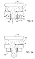
- Referring to
Figs. 4-4A , a system can be operated to continuously direct ink into thecontrol apertures 32 when not ejecting drops to avoid ink stagnation or ink drying in theapertures 32. Referring toFig. 4 , theactuator 15 is controlled to cause anink bolus 27 to extend from thenozzle 17, but without sufficient energy to eject a drop. Referring toFig. 4A , at a point of extension, thebolus 27 retracts into the nozzle and some of the ink spreads onto the surface ofnozzle plate 18. Theactuator 15 is then operated to create a vacuum on thenozzle 17 andcontrol apertures 32. The ink on the nozzle plate is drawn into thecontrol apertures 32. By periodically or continuously cycling the ink, a flow is induced to refresh the ink in theapertures 32. - Referring to
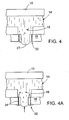
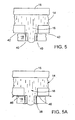
Figs. 5-5A ,control apertures 40 are in communication with a vacuum source that is isolated from the ink supply. Referring toFig. 5 ,apertures 40 are in communication with achannel 42 that leads to a vacuum source such as a mechanical vacuum apparatus (not shown) that intermittently or continuously creates a vacuum. Referring toFig. 5A , the vacuum draws waste ink from the nozzle plate (arrows 46). The ink drawn from the nozzle plate can be recycled to an ink supply or directed to a waste container. The apertures can have non-circular cross-sections. For example, the apertures can be oval-shaped with the major axis of the oval aligned with the radius of the nozzle opening. - Referring to
Fig. 6 ,control apertures 50 include anabsorbent material 52 to encouragewaste ink 38 flow by wicking or capillary action. Theabsorbent material 52 can be disposed in achannel 54 which leads to a bulk container of ink (not shown). The material 52 can protrude slightly above the surface of thenozzle plate 18. Suitable wicking materials include polymeric foams, e.g., a polyurethane foam, or other porous material. The polyurethane precursor material can be delivered to the apertures as a low viscosity fluid which polymerizes in- situ within the apertures, forming the wicking material. - The apertures and/or the nozzle opening in any of the above described embodiments can be formed by machining, laser ablation, or chemical or plasma etching. The apertures can also be formed by molding, e.g., injection molding. The apertures and nozzle opening can be formed in a common body or in separate bodies that are assembled. For example, the nozzle opening can be formed in a body that defines other components of an ink flow path, e.g. a pumping chamber and the aperture can be formed in a separate body which is assembled to the body defining the nozzle opening. In other embodiments, the apertures, nozzle opening, and pressure chamber are formed in a common body. The body can be a metal, carbon or an etchable material such as silicon material, e.g., silicon, silicon dioxide, a silicon nitride, or other etchable materials. Forming printhead components using etching techniques is further described in
U.S. Serial No. 10/189,947, filed July 3, 2002 U.S. Serial No. 60/510,459, filed October 10, 2003 - The apertures can be used in combination with other waste fluid control features such as projections described in
U.S. Serial Number 10/749,816 , filed December 30, 2003U.S. Serial Number 10/749,622, filed December 30, 2003U.S. Serial Number 10/749,833, filed December 30, 2003 - In embodiments, the drop ejection system can be utilized to eject fluids other than ink. For example, the deposited droplets may be a UV or other radiation curable material or other material, for example, chemical or biological fluids, capable of being delivered as drops. For example, the apparatus described could be part of a precision dispensing system. The actuator can be an electromechanical or thermal actuator. For example, the actuator can be electrostatic.
- Other embodiments are within the scope of the following claims.
Claims (22)
- A drop ejection device, comprising:nozzle openings;a flow path corresponding to each nozzle opening, wherein fluid is pressurized in the flow path to eject drops from the corresponding nozzle opening;a piezoelectric actuator for pressurizing said fluid; andwaste fluid control aperturescharacterized in thatthe waste fluid control apertures are surrounding- each nozzle opening and are in communication with a vacuum source.
- The device of claim 1 wherein the fluid control apertures are spaced from the nozzle opening by about 200% of the nozzle opening width or less.
- The device of claim 1 wherein the fluid control apertures are spaced from the nozzle opening by about 200% to about 1000% of the nozzle opening width or less.
- The device of claim 1 wherein the control apertures are in communication with the flow path in which fluid is pressurized.
- The device of claim 1 wherein each control aperture has a fluid resistance of about 25 times or more than the fluidic resistance of the nozzle opening.
- The device of claim 1 wherein the average total flow through the apertures is about 10% or less than the average flow through the nozzle opening.
- The device of claim 1 wherein each aperture has a width of about 30% or less than the width of the nozzle opening.
- The device of claim 1 wherein the width of the nozzle opening is about 200 microns or less.
- The device of claim 1 wherein each control aperture has a diameter of about 10 microns or less.
- The device of claim 1 further including a nonwetting coating between the surrounding apertures and the nozzle opening.
- The device of claim 1 wherein the flow path, nozzle opening, and control aperture are defined in common body.
- The device of claim 11 wherein the body is a silicon material.
- The device of claim 1 wherein the control apertures are isolated from the flow path.
- The device of claim 1 wherein the control apertures include a wicking material.
- The device of claim 1 wherein the control apertures communicate with a waste container.
- A method of ejecting fluid, comprising:providing a fluid drop ejection apparatus including nozzle openings and waste fluid control apertures;ejecting fluid at a frequency of about 10 KHz or greater; anddrawing waste fluid through said apertures in an amount of about 5% or less of the fluid ejected;characterized in thatthe waste fluid control apertures are surrounding each nozzle opening-and are in communication with a vacuum source.
- The method of claim 16 including at least three apertures surrounding each nozzle opening.
- The method of claim 16 comprising drawing about 2% of fluid ejected at about 2 inches of water or less.
- The method of claim 16 wherein the control aperture and the nozzle opening are in communication with a common fluid supply and the fluid supply and the vacuum are communicated through said fluid supply.
- The method of claim 16 wherein the control aperture is about 30% or less the diameter of the nozzle opening.
- The method of claim 16 wherein the diameter of the nozzle opening is about 200 microns or less.
- The method of claim 23 16 comprising drawing waste fluid through said apertures in an amount of about 5% or less of the fluid ejected at an operating vacuum of about 5 inches of water gauge, inwg, or less.
Priority Applications (1)
| Application Number | Priority Date | Filing Date | Title |
|---|---|---|---|
| EP11183973A EP2415606A3 (en) | 2003-12-30 | 2004-12-29 | Drop ejection assembly |
Applications Claiming Priority (5)
| Application Number | Priority Date | Filing Date | Title |
|---|---|---|---|
| US10/749,816 US7121646B2 (en) | 2003-12-30 | 2003-12-30 | Drop ejection assembly |
| US10/749,622 US7168788B2 (en) | 2003-12-30 | 2003-12-30 | Drop ejection assembly |
| US10/749,833 US7303259B2 (en) | 2003-12-30 | 2003-12-30 | Drop ejection assembly |
| US10/749,829 US7237875B2 (en) | 2003-12-30 | 2003-12-30 | Drop ejection assembly |
| PCT/US2004/043946 WO2005065378A2 (en) | 2003-12-30 | 2004-12-29 | Drop ejection assembly |
Related Child Applications (1)
| Application Number | Title | Priority Date | Filing Date |
|---|---|---|---|
| EP11183973.4 Division-Into | 2011-10-05 |
Publications (3)
| Publication Number | Publication Date |
|---|---|
| EP1706270A2 EP1706270A2 (en) | 2006-10-04 |
| EP1706270A4 EP1706270A4 (en) | 2009-08-19 |
| EP1706270B1 true EP1706270B1 (en) | 2011-12-28 |
Family
ID=34753903
Family Applications (4)
| Application Number | Title | Priority Date | Filing Date |
|---|---|---|---|
| EP11183973A Withdrawn EP2415606A3 (en) | 2003-12-30 | 2004-12-29 | Drop ejection assembly |
| EP04815609A Active EP1706269B1 (en) | 2003-12-30 | 2004-12-29 | Drop ejection assembly |
| EP04817071A Active EP1706270B1 (en) | 2003-12-30 | 2004-12-29 | Drop ejection assembly |
| EP04815778A Active EP1706266B1 (en) | 2003-12-30 | 2004-12-29 | Drop ejection assembly |
Family Applications Before (2)
| Application Number | Title | Priority Date | Filing Date |
|---|---|---|---|
| EP11183973A Withdrawn EP2415606A3 (en) | 2003-12-30 | 2004-12-29 | Drop ejection assembly |
| EP04815609A Active EP1706269B1 (en) | 2003-12-30 | 2004-12-29 | Drop ejection assembly |
Family Applications After (1)
| Application Number | Title | Priority Date | Filing Date |
|---|---|---|---|
| EP04815778A Active EP1706266B1 (en) | 2003-12-30 | 2004-12-29 | Drop ejection assembly |
Country Status (5)
| Country | Link |
|---|---|
| EP (4) | EP2415606A3 (en) |
| JP (4) | JP2007516876A (en) |
| KR (3) | KR101220272B1 (en) |
| AT (2) | ATE538933T1 (en) |
| WO (3) | WO2005065331A2 (en) |
Families Citing this family (10)
| Publication number | Priority date | Publication date | Assignee | Title |
|---|---|---|---|---|
| JP4665660B2 (en) * | 2005-08-19 | 2011-04-06 | セイコーエプソン株式会社 | NOZZLE PLATE, MANUFACTURING METHOD THEREOF, AND LIQUID DISCHARGE HEAD |
| US8136934B2 (en) | 2009-02-18 | 2012-03-20 | Xerox Corporation | Waste phase change ink recycling |
| JP5764312B2 (en) * | 2010-11-05 | 2015-08-19 | 富士フイルム株式会社 | Ink jet recording apparatus and nozzle plate cleaning method |
| JP5863337B2 (en) * | 2011-08-25 | 2016-02-16 | キヤノン株式会社 | Inkjet recording head |
| US8517518B2 (en) | 2010-11-09 | 2013-08-27 | Canon Kabushiki Kaisha | Recording apparatus and liquid ejection head |
| FR2968597A1 (en) * | 2010-12-13 | 2012-06-15 | Centre Nat Rech Scient | INKJET DEVICE HAVING FLUID EXTRACTION MEANS AND INK JET METHOD THEREOF |
| JP5934161B2 (en) | 2013-09-09 | 2016-06-15 | 武蔵エンジニアリング株式会社 | Nozzle and liquid material discharge apparatus including the nozzle |
| JP6193442B2 (en) * | 2016-05-06 | 2017-09-06 | 武蔵エンジニアリング株式会社 | Liquid material discharge device |
| JP7008270B2 (en) | 2017-04-24 | 2022-01-25 | ブラザー工業株式会社 | Liquid discharger and inkjet printer |
| WO2023223196A1 (en) * | 2022-05-16 | 2023-11-23 | Merxin Ltd | Nozzle arrangement |
Family Cites Families (40)
| Publication number | Priority date | Publication date | Assignee | Title |
|---|---|---|---|---|
| IT1109303B (en) * | 1978-10-30 | 1985-12-16 | Ipm Ind Politecnica Meridional | UNI-AXIS ANISOTROP MAGNETIZATION CREDIT CARD |
| GB2061831B (en) * | 1979-11-07 | 1984-02-29 | Matsushita Electric Ind Co Ltd | Ink jet writing head with spacer in capillary chamber |
| JPS5763266A (en) * | 1980-10-02 | 1982-04-16 | Seiko Epson Corp | Ink jet head |
| DE3048259A1 (en) * | 1980-12-20 | 1982-07-29 | Philips Patentverwaltung Gmbh, 2000 Hamburg | "NOZZLE FOR INK JET PRINTER" |
| US4459601A (en) * | 1981-01-30 | 1984-07-10 | Exxon Research And Engineering Co. | Ink jet method and apparatus |
| JPS57188372A (en) * | 1981-01-30 | 1982-11-19 | Exxon Research Engineering Co | Ink jet device |
| JPS5995157A (en) * | 1982-11-23 | 1984-06-01 | Yokogawa Hewlett Packard Ltd | Head for bubble driven ink jet printer |
| US4528996A (en) * | 1983-12-22 | 1985-07-16 | The Mead Corporation | Orifice plate cleaning system |
| JPS61115644U (en) * | 1984-12-28 | 1986-07-22 | ||
| US4613875A (en) * | 1985-04-08 | 1986-09-23 | Tektronix, Inc. | Air assisted ink jet head with projecting internal ink drop-forming orifice outlet |
| JPS6219247A (en) * | 1985-07-16 | 1987-01-28 | Toray Ind Inc | Method for eliminating colloidal substance |
| JPS62150145U (en) * | 1986-03-18 | 1987-09-22 | ||
| US4825227A (en) | 1988-02-29 | 1989-04-25 | Spectra, Inc. | Shear mode transducer for ink jet systems |
| US4992802A (en) * | 1988-12-22 | 1991-02-12 | Hewlett-Packard Company | Method and apparatus for extending the environmental operating range of an ink jet print cartridge |
| US4937598A (en) | 1989-03-06 | 1990-06-26 | Spectra, Inc. | Ink supply system for an ink jet head |
| US5265315A (en) | 1990-11-20 | 1993-11-30 | Spectra, Inc. | Method of making a thin-film transducer ink jet head |
| JPH05155028A (en) * | 1991-12-04 | 1993-06-22 | Ricoh Co Ltd | Ink jet head |
| CA2126232C (en) | 1992-10-19 | 2000-05-16 | Makiko Kimura | Ink jet head having an improved ink discharging outlet face and ink jet apparatus provided with said ink jet head |
| US5659346A (en) | 1994-03-21 | 1997-08-19 | Spectra, Inc. | Simplified ink jet head |
| US5604521A (en) * | 1994-06-30 | 1997-02-18 | Compaq Computer Corporation | Self-aligning orifice plate for ink jet printheads |
| KR100196668B1 (en) | 1994-07-20 | 1999-06-15 | 브라이언 에프. 왈쉬 | High frequency drop-on-demand ink jet system |
| JPH08230185A (en) * | 1995-03-01 | 1996-09-10 | Brother Ind Ltd | Ink jet device |
| JP3315589B2 (en) * | 1995-06-21 | 2002-08-19 | キヤノン株式会社 | Ink tank and recording apparatus provided with the same |
| JP3386099B2 (en) * | 1995-07-03 | 2003-03-10 | セイコーエプソン株式会社 | Nozzle plate for ink jet recording head, method of manufacturing the same, and ink jet recording head |
| US6270191B1 (en) | 1997-06-04 | 2001-08-07 | Seiko Epson Corporation | Ink jet recording head and ink jet recorder |
| US6235212B1 (en) * | 1997-07-15 | 2001-05-22 | Silverbrook Research Pty Ltd | Method of manufacture of an electrostatic ink jet printer |
| US6264307B1 (en) * | 1997-07-15 | 2001-07-24 | Silverbrook Research Pty Ltd | Buckle grill oscillating pressure ink jet printing mechanism |
| US5853861A (en) * | 1997-09-30 | 1998-12-29 | E. I. Du Pont De Nemours And Company | Ink jet printing of textiles |
| US6132028A (en) * | 1998-05-14 | 2000-10-17 | Hewlett-Packard Company | Contoured orifice plate of thermal ink jet print head |
| GB2339170A (en) * | 1998-07-25 | 2000-01-19 | Markem Tech Ltd | Printhead with integral ink gutter |
| US6267464B1 (en) * | 1998-12-28 | 2001-07-31 | Eastman Kodak Company | Self cleaning ink jet printhead cartridges |
| US6283575B1 (en) * | 1999-05-10 | 2001-09-04 | Eastman Kodak Company | Ink printing head with gutter cleaning structure and method of assembling the printer |
| JP2001038917A (en) * | 1999-07-29 | 2001-02-13 | Casio Comput Co Ltd | Ink jet printer |
| JP2001212966A (en) * | 2000-02-04 | 2001-08-07 | Seiko Epson Corp | Hydrophilic structure and ink-jet recording head |
| JP3501083B2 (en) * | 2000-03-21 | 2004-02-23 | 富士ゼロックス株式会社 | Nozzle for inkjet recording head and method of manufacturing the same |
| JP2002187295A (en) * | 2000-12-22 | 2002-07-02 | Hitachi Koki Co Ltd | Ink jet print head and method for sweeping waste ink |
| TW541248B (en) * | 2001-03-16 | 2003-07-11 | Benq Corp | Ink cartridge |
| JP4731763B2 (en) * | 2001-09-12 | 2011-07-27 | キヤノン株式会社 | Liquid jet recording head and manufacturing method thereof |
| US6820963B2 (en) * | 2001-12-13 | 2004-11-23 | Hewlett-Packard Development Company, L.P. | Fluid ejection head |
| US6637862B2 (en) * | 2002-02-08 | 2003-10-28 | Illinois Tool Works, Inc. | Maintenance module for fluid jet device |
-
2004
- 2004-12-29 KR KR1020067015516A patent/KR101220272B1/en active IP Right Grant
- 2004-12-29 JP JP2006547448A patent/JP2007516876A/en active Pending
- 2004-12-29 EP EP11183973A patent/EP2415606A3/en not_active Withdrawn
- 2004-12-29 WO PCT/US2004/043776 patent/WO2005065331A2/en active Application Filing
- 2004-12-29 EP EP04815609A patent/EP1706269B1/en active Active
- 2004-12-29 EP EP04817071A patent/EP1706270B1/en active Active
- 2004-12-29 JP JP2006547520A patent/JP2007516878A/en active Pending
- 2004-12-29 WO PCT/US2004/043946 patent/WO2005065378A2/en active Application Filing
- 2004-12-29 WO PCT/US2004/043577 patent/WO2005065294A2/en active Application Filing
- 2004-12-29 EP EP04815778A patent/EP1706266B1/en active Active
- 2004-12-29 JP JP2006547572A patent/JP2007516879A/en active Pending
- 2004-12-29 AT AT04815778T patent/ATE538933T1/en active
- 2004-12-29 KR KR1020067015517A patent/KR101154554B1/en active IP Right Grant
- 2004-12-29 KR KR1020067015519A patent/KR101222582B1/en active IP Right Grant
- 2004-12-29 AT AT04817071T patent/ATE538934T1/en active
-
2011
- 2011-04-21 JP JP2011094894A patent/JP4959013B2/en active Active
Also Published As
| Publication number | Publication date |
|---|---|
| EP1706266A4 (en) | 2009-08-12 |
| EP2415606A2 (en) | 2012-02-08 |
| EP1706270A2 (en) | 2006-10-04 |
| WO2005065331A2 (en) | 2005-07-21 |
| JP2007516876A (en) | 2007-06-28 |
| JP2007516878A (en) | 2007-06-28 |
| WO2005065294A3 (en) | 2005-11-17 |
| JP2011161926A (en) | 2011-08-25 |
| KR101222582B1 (en) | 2013-01-16 |
| EP1706266A2 (en) | 2006-10-04 |
| ATE538934T1 (en) | 2012-01-15 |
| KR101220272B1 (en) | 2013-01-09 |
| KR20060127955A (en) | 2006-12-13 |
| JP2007516879A (en) | 2007-06-28 |
| KR20060127957A (en) | 2006-12-13 |
| JP4959013B2 (en) | 2012-06-20 |
| EP1706270A4 (en) | 2009-08-19 |
| ATE538933T1 (en) | 2012-01-15 |
| WO2005065331A3 (en) | 2006-12-28 |
| KR101154554B1 (en) | 2012-06-14 |
| EP1706269A4 (en) | 2009-08-19 |
| EP1706269B1 (en) | 2012-06-13 |
| WO2005065294A2 (en) | 2005-07-21 |
| EP2415606A3 (en) | 2012-05-09 |
| KR20060127954A (en) | 2006-12-13 |
| WO2005065378A2 (en) | 2005-07-21 |
| EP1706266B1 (en) | 2011-12-28 |
| WO2005065378A3 (en) | 2006-02-23 |
| EP1706269A2 (en) | 2006-10-04 |
Similar Documents
| Publication | Publication Date | Title |
|---|---|---|
| US8287093B2 (en) | Drop ejection assembly | |
| JP4959013B2 (en) | Droplet ejection assembly | |
| EP3212409B1 (en) | Fluid ejection device | |
| US7121646B2 (en) | Drop ejection assembly | |
| JP2007516879A5 (en) | ||
| US7303259B2 (en) | Drop ejection assembly | |
| US7168788B2 (en) | Drop ejection assembly | |
| EP1706271B1 (en) | Drop ejection assembly |
Legal Events
| Date | Code | Title | Description |
|---|---|---|---|
| PUAI | Public reference made under article 153(3) epc to a published international application that has entered the european phase |
Free format text: ORIGINAL CODE: 0009012 |
|
| 17P | Request for examination filed |
Effective date: 20060727 |
|
| AK | Designated contracting states |
Kind code of ref document: A2 Designated state(s): AT BE BG CH CY CZ DE DK EE ES FI FR GB GR HU IE IS IT LI LT LU MC NL PL PT RO SE SI SK TR |
|
| DAX | Request for extension of the european patent (deleted) | ||
| A4 | Supplementary search report drawn up and despatched |
Effective date: 20090721 |
|
| RIC1 | Information provided on ipc code assigned before grant |
Ipc: B41J 2/165 20060101ALI20090715BHEP Ipc: B41J 2/14 20060101AFI20090715BHEP Ipc: B41J 2/045 20060101ALI20090715BHEP |
|
| 17Q | First examination report despatched |
Effective date: 20091125 |
|
| GRAP | Despatch of communication of intention to grant a patent |
Free format text: ORIGINAL CODE: EPIDOSNIGR1 |
|
| GRAS | Grant fee paid |
Free format text: ORIGINAL CODE: EPIDOSNIGR3 |
|
| GRAA | (expected) grant |
Free format text: ORIGINAL CODE: 0009210 |
|
| AK | Designated contracting states |
Kind code of ref document: B1 Designated state(s): AT BE BG CH CY CZ DE DK EE ES FI FR GB GR HU IE IS IT LI LT LU MC NL PL PT RO SE SI SK TR |
|
| REG | Reference to a national code |
Ref country code: GB Ref legal event code: FG4D |
|
| REG | Reference to a national code |
Ref country code: CH Ref legal event code: EP |
|
| REG | Reference to a national code |
Ref country code: AT Ref legal event code: REF Ref document number: 538934 Country of ref document: AT Kind code of ref document: T Effective date: 20120115 |
|
| REG | Reference to a national code |
Ref country code: IE Ref legal event code: FG4D |
|
| REG | Reference to a national code |
Ref country code: DE Ref legal event code: R096 Ref document number: 602004035917 Country of ref document: DE Effective date: 20120223 |
|
| REG | Reference to a national code |
Ref country code: NL Ref legal event code: VDEP Effective date: 20111228 |
|
| PG25 | Lapsed in a contracting state [announced via postgrant information from national office to epo] |
Ref country code: LT Free format text: LAPSE BECAUSE OF FAILURE TO SUBMIT A TRANSLATION OF THE DESCRIPTION OR TO PAY THE FEE WITHIN THE PRESCRIBED TIME-LIMIT Effective date: 20111228 |
|
| LTIE | Lt: invalidation of european patent or patent extension |
Effective date: 20111228 |
|
| PG25 | Lapsed in a contracting state [announced via postgrant information from national office to epo] |
Ref country code: SE Free format text: LAPSE BECAUSE OF FAILURE TO SUBMIT A TRANSLATION OF THE DESCRIPTION OR TO PAY THE FEE WITHIN THE PRESCRIBED TIME-LIMIT Effective date: 20111228 Ref country code: GR Free format text: LAPSE BECAUSE OF FAILURE TO SUBMIT A TRANSLATION OF THE DESCRIPTION OR TO PAY THE FEE WITHIN THE PRESCRIBED TIME-LIMIT Effective date: 20120329 Ref country code: SI Free format text: LAPSE BECAUSE OF FAILURE TO SUBMIT A TRANSLATION OF THE DESCRIPTION OR TO PAY THE FEE WITHIN THE PRESCRIBED TIME-LIMIT Effective date: 20111228 |
|
| PG25 | Lapsed in a contracting state [announced via postgrant information from national office to epo] |
Ref country code: BE Free format text: LAPSE BECAUSE OF FAILURE TO SUBMIT A TRANSLATION OF THE DESCRIPTION OR TO PAY THE FEE WITHIN THE PRESCRIBED TIME-LIMIT Effective date: 20111228 Ref country code: CY Free format text: LAPSE BECAUSE OF FAILURE TO SUBMIT A TRANSLATION OF THE DESCRIPTION OR TO PAY THE FEE WITHIN THE PRESCRIBED TIME-LIMIT Effective date: 20111228 |
|
| PG25 | Lapsed in a contracting state [announced via postgrant information from national office to epo] |
Ref country code: EE Free format text: LAPSE BECAUSE OF FAILURE TO SUBMIT A TRANSLATION OF THE DESCRIPTION OR TO PAY THE FEE WITHIN THE PRESCRIBED TIME-LIMIT Effective date: 20111228 Ref country code: MC Free format text: LAPSE BECAUSE OF NON-PAYMENT OF DUE FEES Effective date: 20111231 Ref country code: IS Free format text: LAPSE BECAUSE OF FAILURE TO SUBMIT A TRANSLATION OF THE DESCRIPTION OR TO PAY THE FEE WITHIN THE PRESCRIBED TIME-LIMIT Effective date: 20120428 Ref country code: SK Free format text: LAPSE BECAUSE OF FAILURE TO SUBMIT A TRANSLATION OF THE DESCRIPTION OR TO PAY THE FEE WITHIN THE PRESCRIBED TIME-LIMIT Effective date: 20111228 Ref country code: NL Free format text: LAPSE BECAUSE OF FAILURE TO SUBMIT A TRANSLATION OF THE DESCRIPTION OR TO PAY THE FEE WITHIN THE PRESCRIBED TIME-LIMIT Effective date: 20111228 Ref country code: BG Free format text: LAPSE BECAUSE OF FAILURE TO SUBMIT A TRANSLATION OF THE DESCRIPTION OR TO PAY THE FEE WITHIN THE PRESCRIBED TIME-LIMIT Effective date: 20120328 Ref country code: CZ Free format text: LAPSE BECAUSE OF FAILURE TO SUBMIT A TRANSLATION OF THE DESCRIPTION OR TO PAY THE FEE WITHIN THE PRESCRIBED TIME-LIMIT Effective date: 20111228 |
|
| REG | Reference to a national code |
Ref country code: CH Ref legal event code: PL |
|
| PG25 | Lapsed in a contracting state [announced via postgrant information from national office to epo] |
Ref country code: RO Free format text: LAPSE BECAUSE OF FAILURE TO SUBMIT A TRANSLATION OF THE DESCRIPTION OR TO PAY THE FEE WITHIN THE PRESCRIBED TIME-LIMIT Effective date: 20111228 Ref country code: PL Free format text: LAPSE BECAUSE OF FAILURE TO SUBMIT A TRANSLATION OF THE DESCRIPTION OR TO PAY THE FEE WITHIN THE PRESCRIBED TIME-LIMIT Effective date: 20111228 Ref country code: PT Free format text: LAPSE BECAUSE OF FAILURE TO SUBMIT A TRANSLATION OF THE DESCRIPTION OR TO PAY THE FEE WITHIN THE PRESCRIBED TIME-LIMIT Effective date: 20120430 |
|
| REG | Reference to a national code |
Ref country code: AT Ref legal event code: MK05 Ref document number: 538934 Country of ref document: AT Kind code of ref document: T Effective date: 20111228 |
|
| REG | Reference to a national code |
Ref country code: IE Ref legal event code: MM4A |
|
| PG25 | Lapsed in a contracting state [announced via postgrant information from national office to epo] |
Ref country code: CH Free format text: LAPSE BECAUSE OF NON-PAYMENT OF DUE FEES Effective date: 20111231 Ref country code: LI Free format text: LAPSE BECAUSE OF NON-PAYMENT OF DUE FEES Effective date: 20111231 Ref country code: DK Free format text: LAPSE BECAUSE OF FAILURE TO SUBMIT A TRANSLATION OF THE DESCRIPTION OR TO PAY THE FEE WITHIN THE PRESCRIBED TIME-LIMIT Effective date: 20111228 Ref country code: IE Free format text: LAPSE BECAUSE OF NON-PAYMENT OF DUE FEES Effective date: 20111229 |
|
| PLBE | No opposition filed within time limit |
Free format text: ORIGINAL CODE: 0009261 |
|
| STAA | Information on the status of an ep patent application or granted ep patent |
Free format text: STATUS: NO OPPOSITION FILED WITHIN TIME LIMIT |
|
| PG25 | Lapsed in a contracting state [announced via postgrant information from national office to epo] |
Ref country code: IT Free format text: LAPSE BECAUSE OF FAILURE TO SUBMIT A TRANSLATION OF THE DESCRIPTION OR TO PAY THE FEE WITHIN THE PRESCRIBED TIME-LIMIT Effective date: 20111228 |
|
| 26N | No opposition filed |
Effective date: 20121001 |
|
| REG | Reference to a national code |
Ref country code: DE Ref legal event code: R097 Ref document number: 602004035917 Country of ref document: DE Effective date: 20121001 |
|
| PG25 | Lapsed in a contracting state [announced via postgrant information from national office to epo] |
Ref country code: AT Free format text: LAPSE BECAUSE OF FAILURE TO SUBMIT A TRANSLATION OF THE DESCRIPTION OR TO PAY THE FEE WITHIN THE PRESCRIBED TIME-LIMIT Effective date: 20111228 |
|
| PG25 | Lapsed in a contracting state [announced via postgrant information from national office to epo] |
Ref country code: ES Free format text: LAPSE BECAUSE OF FAILURE TO SUBMIT A TRANSLATION OF THE DESCRIPTION OR TO PAY THE FEE WITHIN THE PRESCRIBED TIME-LIMIT Effective date: 20120408 |
|
| PG25 | Lapsed in a contracting state [announced via postgrant information from national office to epo] |
Ref country code: LU Free format text: LAPSE BECAUSE OF NON-PAYMENT OF DUE FEES Effective date: 20111229 |
|
| PG25 | Lapsed in a contracting state [announced via postgrant information from national office to epo] |
Ref country code: FI Free format text: LAPSE BECAUSE OF FAILURE TO SUBMIT A TRANSLATION OF THE DESCRIPTION OR TO PAY THE FEE WITHIN THE PRESCRIBED TIME-LIMIT Effective date: 20111228 |
|
| PG25 | Lapsed in a contracting state [announced via postgrant information from national office to epo] |
Ref country code: TR Free format text: LAPSE BECAUSE OF FAILURE TO SUBMIT A TRANSLATION OF THE DESCRIPTION OR TO PAY THE FEE WITHIN THE PRESCRIBED TIME-LIMIT Effective date: 20111228 |
|
| PG25 | Lapsed in a contracting state [announced via postgrant information from national office to epo] |
Ref country code: HU Free format text: LAPSE BECAUSE OF FAILURE TO SUBMIT A TRANSLATION OF THE DESCRIPTION OR TO PAY THE FEE WITHIN THE PRESCRIBED TIME-LIMIT Effective date: 20111228 |
|
| REG | Reference to a national code |
Ref country code: FR Ref legal event code: PLFP Year of fee payment: 12 |
|
| REG | Reference to a national code |
Ref country code: FR Ref legal event code: PLFP Year of fee payment: 13 |
|
| REG | Reference to a national code |
Ref country code: FR Ref legal event code: PLFP Year of fee payment: 14 |
|
| PGFP | Annual fee paid to national office [announced via postgrant information from national office to epo] |
Ref country code: GB Payment date: 20231109 Year of fee payment: 20 |
|
| PGFP | Annual fee paid to national office [announced via postgrant information from national office to epo] |
Ref country code: FR Payment date: 20231108 Year of fee payment: 20 Ref country code: DE Payment date: 20231031 Year of fee payment: 20 |